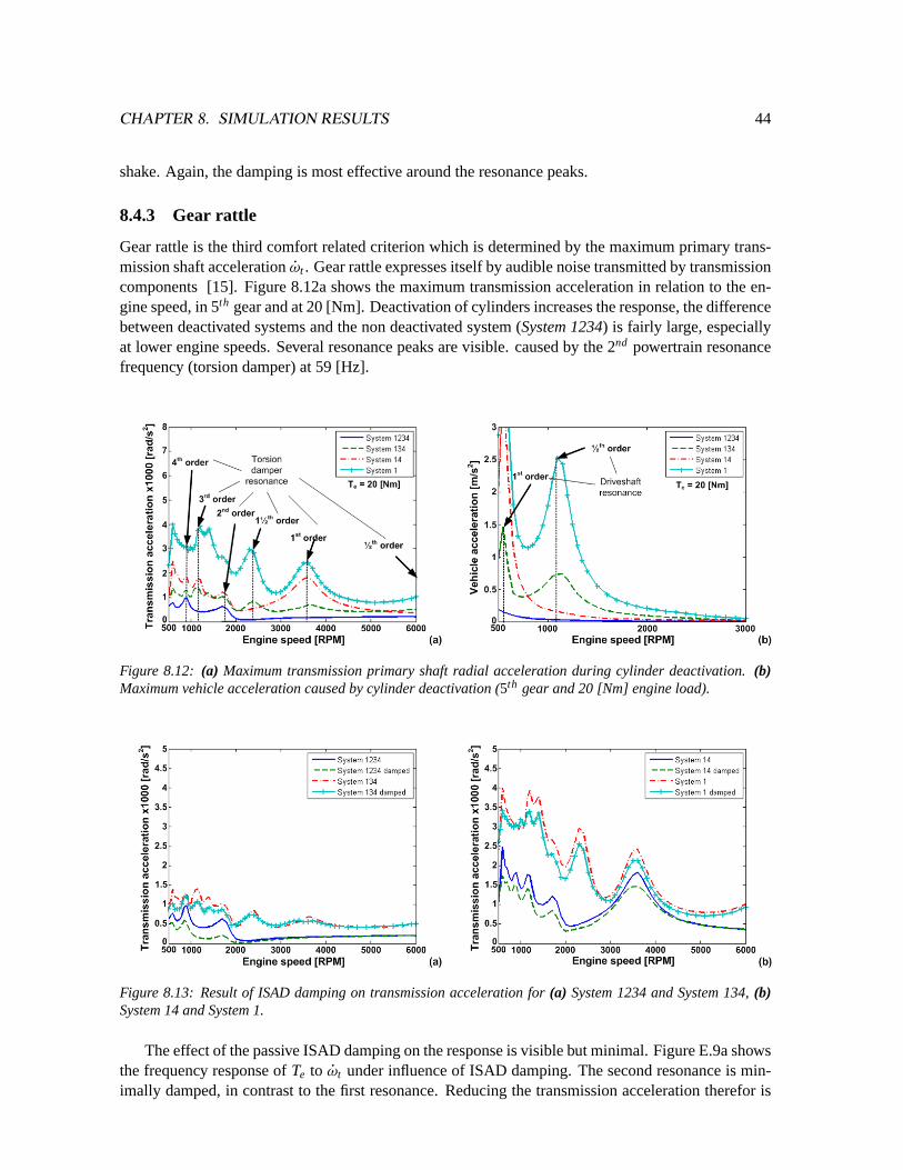
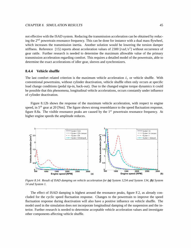
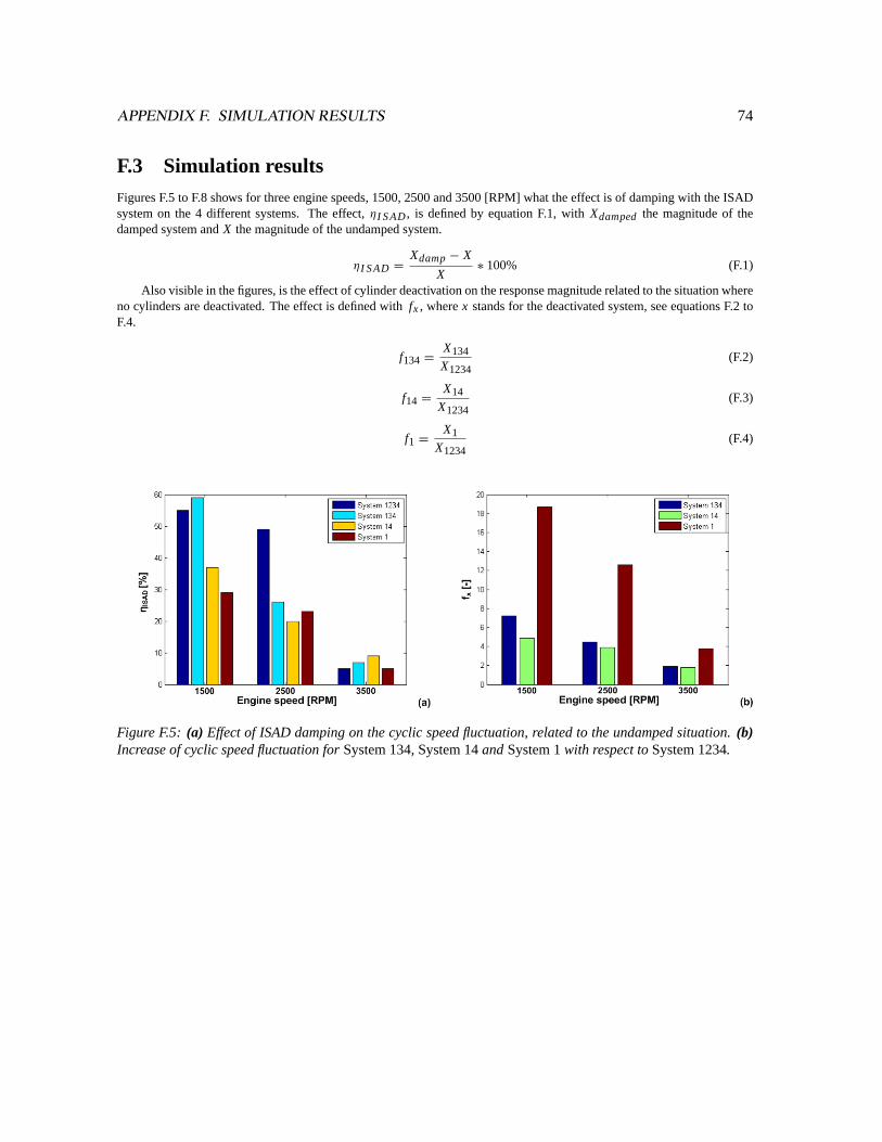
Cylinder deactivation on 4 cylinder engines Peters, G.F.A. Published: 01/01/2007 Document Version Publisher’s PDF, also known as Version of Record (includes final page, issue and volume numbers) Please check the document version of this publication: • A submitted manuscript is the author's version of the article upon submission and before peer-review. There can be important differences between the submitted version and the official published version of record. People interested in the research are advised to contact the author for the final version of the publication, or visit the DOI to the publisher's website. • The final author version and the galley proof are versions of the publication after peer review. • The final published version features the final layout of the paper including the volume, issue and page numbers. Link to publication Citation for published version (APA): Peters, G. (2007). Cylinder deactivation on 4 cylinder engines: a torsional vibration analysis. (DCT rapporten; Vol. 2007.011). Eindhoven: Technische Universiteit Eindhoven. General rights Copyright and moral rights for the publications made accessible in the public portal are retained by the authors and/or other copyright owners and it is a condition of accessing publications that users recognise and abide by the legal requirements associated with these rights. • Users may download and print one copy of any publication from the public portal for the purpose of private study or research. • You may not further distribute the material or use it for any profit-making activity or commercial gain • You may freely distribute the URL identifying the publication in the public portal ? Take down policy If you believe that this document breaches copyright please contact us providing details, and we will remove access to the work immediately and investigate your claim. Download date: 10. May. 2018
Transcript
Cylinder deactivation on 4 cylinder engines
Peters, G.F.A.
Published: 01/01/2007
Document VersionPublisher’s PDF, also known as Version of Record (includes final page, issue and volume numbers)
Please check the document version of this publication:
• A submitted manuscript is the author's version of the article upon submission and before peer-review. There can be important differencesbetween the submitted version and the official published version of record. People interested in the research are advised to contact theauthor for the final version of the publication, or visit the DOI to the publisher's website.• The final author version and the galley proof are versions of the publication after peer review.• The final published version features the final layout of the paper including the volume, issue and page numbers.
Link to publication
Citation for published version (APA):Peters, G. (2007). Cylinder deactivation on 4 cylinder engines: a torsional vibration analysis. (DCT rapporten;Vol. 2007.011). Eindhoven: Technische Universiteit Eindhoven.
General rightsCopyright and moral rights for the publications made accessible in the public portal are retained by the authors and/or other copyright ownersand it is a condition of accessing publications that users recognise and abide by the legal requirements associated with these rights.
• Users may download and print one copy of any publication from the public portal for the purpose of private study or research. • You may not further distribute the material or use it for any profit-making activity or commercial gain • You may freely distribute the URL identifying the publication in the public portal ?
Take down policyIf you believe that this document breaches copyright please contact us providing details, and we will remove access to the work immediatelyand investigate your claim.
Cylinder deactivation on 4 cylinder engines:A torsional vibration analysis
Gilbert Peters
DCT 2007-11
February 15, 2007Eindhoven University of Technology (TU/e)
G.F.A. Peters s0552954 (TU/e)
Supervisor: (TU/e) Bram Veenhuizen
Summary
The project ”car of the future” is a project aimed at designing a sustainable passenger car for theyear 2020. Sustainability is a very broad topic, which reaches further than fuel economy and exhaustemissions. The ”car of the future” uses a modularity concept to maximize the sustainability aspect ofthe vehicle in a broad sense. The modularity concept makes it possible to use different powertrains,creating the opportunity to adapt the vehicle to the availability of fuels, or adapt the powertrain tothe demands of the user in the future. The desire for flexibility justifies the choice for an internalcombustion engine as primary mover, because it can be adapted to a large variety of fuels with moreor less modifications to its construction.
Reducing the fuel consumption and the related CO2 emissions is increasingly important thesedays. Increasing the powertrain efficiency is therefor one of the major goals within the project ”carof the future”. Typically, internal combustion engines operate more efficiently when the engine loadis high. Engine load during daily traffic however is typically low, resulting in sub-optimal fuel con-sumption. Better matching of the real engine load with the optimal engine load can be obtained byapplying cylinder deactivation. By deactivation of cylinders the load of the still activated cylinder isincreased with improved efficiency as a consequence.
Cylinder deactivation increases the torsional vibrations of the engine because of the reduced com-bustion interval and increased combustion peaks. Currently, cylinder deactivation is used on multi-cylinder engines, V12, V8 or V6, where the torsional vibrations do not cause much of a problem dueto the still acceptable combustion intervals and combustion peaks during deactivation. In Europe, themajority of passenger cars use a 4 cylinder engine, therefor the research has been focussed on thevibrational powertrain behavior of four cylinder engines using cylinder deactivation. The goal of thisresearch is therefor:
”Determine the influence of cylinder deactivation on a 4-cylinder engine, regarding the vibra-tional behavior of the powertrain.”
In order to analyze the effect of cylinder deactivation on powertrain dynamics, the important crite-ria regarding powertrain vibrations are analyzed. The important criteria regarding powertrain comfortwhich are studied are ”engine shake”, ”gear rattle” and ”vehicle shuffle”. Vibrations can be sup-pressed or damped by using for instance a torsion damper (TD) or an integrated starter alternatordamper (ISAD), which can apply a positive or negative torque to the crankshaft. The ISAD systemis herein preferred because it makes other powertrain functions possible, like regenerative braking,boosting and start/stop function.
The powertrain with all its components are modeled, in order to analyze the effect of cylinder
i
ii
deactivation on the powertrain dynamics. These models describe the engine dynamics, manual trans-mission, driveshafts, wheels and vehicle. The powertrain can be equipped with a torsion damper orISAD system. Both powertrains are compared by analyzing the frequency responses of both pow-ertrains. Both powertrains show different eigenfrequencies, which can interfere with the engines’excitation frequency. Interference of the eigenfrequencies with the excitation frequencies can causeresonances. Analysis will show which powertrain is best suited in combination with cylinder deacti-vation.
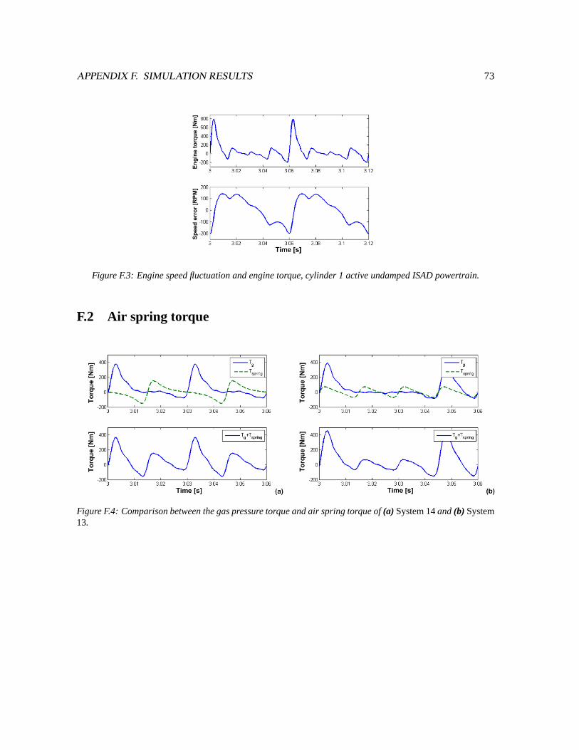
During deactivation the deactivated cylinders are being used as an ”air spring”. The valves of thedeactivated cylinder are kept closed, to minimize the pump work by this cylinder. The trapped airin the cylinder will periodical complete a compression cycle, followed by an expansion cycles. Thetiming of valve closing influences the torque caused by the ”air spring”. Three different valve timingsare being discussed, serving as a starting point for further research.
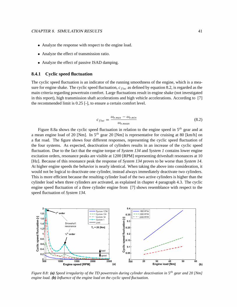
Deactivation of cylinders leads to increased powertrain vibrations. These vibrations are the cyclicspeed fluctuation, primary transmission shaft acceleration, longitudinal vehicle acceleration and pow-ertrain unit acceleration. The influence of the engine speed, engine load and gear ration on thesevibrations are studied. The ISAD system can be used as a passive damper to reduce the vibrationscaused by cylinder deactivation. Simulation results show how effective this damping system is.
Samenvatting
Het project ”auto van de toekomst” is gericht op het ontwerpen van een duurzame personenauto voorhet jaar 2020. Duurzaamheid is een breed begrip en reikt verder dan brandstofverbruik en uitlaat-gas emissies. Om de duurzaamheid in een breed perspectief te kunnen garanderen wordt er gebruikgemaakt van een modulariteitsconcept. Dit modulariteitsconcept maakt het mogelijk om verschil-lende aandrijflijn concepten te gebruiken, waardoor ingespeeld kan worden op de beschikbaarheidvan brandstoffen en op de wensen van de gebruiker en eisen van de overheid. De wens naar flex-ibiliteit verklaard tevens waarom er gekozen is voor een inwendige verbrandingsmotor als primaireaandrijving, welke in staat is om op meerdere brandstoffen te functioneren.
Het terugdringen van het brandstofverbruik en de daaraan gekoppelde CO2 emissie is heden tendagen zeer belangrijk. Het verhogen van het rendement van de aandrijflijn is dan ook een van despeerpunten binnen het project ”auto van de toekomst”. Het rendement van een verbrandingsmotoris in de regel het hoogst bij een hoge motorbelasting. In het dagelijkse verkeer wordt de verbrand-ingsmotor echter slechts licht belast, doordat de vermogensvraag gering is. Hierdoor is het rendementvan de aandrijving laag. Het beter afstemmen van de optimale motor belasting met de werkelijkebelasting kan worden gerealiseerd door middel van cilinder deactivatie. Door het deactiveren van eenof meerdere cilinders, worden de actieve cilinders hoger belast, waardoor het rendement van dezecilinders en daarmee de totale motor toeneemt.
Het deactiveren van cilinders zorgt ervoor dat de dynamica van de verbrandingsmotor veran-derd, met vibraties als gevolg. Cilinder uitschakeling wordt op dit moment alleen toegepast op grotemulti-cilinder motoren, zoals V12, V8 en V6 motoren, waarbij gedurende cilinder uitschakeling hettrillingscomfort gewaarborgd blijft. De meest voorkomende motor configuratie in Europa is echter de4 cilinder motor. Het onderzoek is daarom gericht op het toepassen van cilinder uitschakeling op 4cilinder motoren. Het doel van het onderzoek is daarom ook als volgt gedefinieerd:
”Bepalen van de invloed van cilinder uitschakeling op 4 cilinder motoren, betreffende het vibratiegedrag van de aandrijflijn.”
De belangrijke aandrijflijn criteria met betrekking tot het trillingscomfort zijn bestudeerd, te weten”gear rattle”, ”engine shake” en ”vehicle shuffle”. Vibraties kunnen worden onderdrukt of gedemptdoor gebruik te maken van onder meer een trillingsdemper of een starter/generator, welke function-eert als demper door een positief dan wel negatief koppel aan de krukas te leveren. Gezien de extramogelijkheden die een starter/generator met zich mee brengt heeft dit systeem de voorkeur.
Om het effect van cilinder uitschakeling op de aandrijflijn dynamica te kunnen bestuderen is deaandrijflijn met al zijn componenten gemodelleerd. Deze modellen beschrijven het dynamisch gedrag
iii
iv
van de verbrandingsmotor, de aandrijflijn ophanging, een manuele transmissie, aandrijfassen, wielenen het voertuig. Als vibratie dempers worden zowel de torsie demper (TD), alsook de starter/alternator(ISAD) gebruikt. Dit levert twee verschillende modellen op die op basis van frequentie responsies metelkaar vergeleken zijn. De beide aandrijflijnen vertonen eigenfrequenties die, doordat de excitatie fre-quentie van de verbrandingsmotor afneemt tijdens cilinder uitschakeling, samen kunnen vallen met deexcitatie frequentie en zo resonantie kunnen veroorzaken. Onderzoek wijst uit welke aandrijflijn hetmeest geschikt is voor gebruik in combinatie met cilinder deactivatie.
Tijdens het deactiveren van cilinders, worden de uitgeschakelde cilinder(s) gebruikt als ”luchtveer”. De kleppen van deze cilinder(s) worden gesloten zodat ze geen pomp werk verrichten. Decilinder zal vervolgens periodiek een compressie slag gevolgd door een expansie slag ondergaan, watresulteert in een periodiek koppel verloop. Het moment van sluiten van de kleppen blijkt van invloedop het koppel wat veroorzaakt wordt door de ”lucht veer”. Drie verschillende sluitingstijdstippenworden besproken.
Het deactiveren van cilinders leidt tot een toename in de aandrijflijn vibraties. Hiervoor is gekekennaar motortoerental fluctuaties, primaire transmissie as acceleratie, longitudinale voertuig acceleratieen de aandrijflijn kantel acceleratie. Gekeken is naar de invloed van het motortoerental, overbreng-ingsverhouding en motorbelasting op deze acceleraties en fluctuaties. De resultaten van de simulatieszijn getoetst aan criteria verkregen uit literatuur. De starter generator wordt ingezet als passief demp-ingsysteem, welke de trillingen kan reduceren. Simulatie resultaten laten zien hoe effectief deze wijzevan demping is.
In 2005, the Society of Nature and Environment (Stichting Natuur en Milieu) challenged the 3 DutchUniversities of Technology to design ”A car of the future” for the year 2020. Its objective is to createdemand for clean and clever mobility and encourages the automotive industry to speed up the devel-opment of sustainable mobility solutions. The concept car will be unveiled at the 2007 AmsterdamMotorshow, AutoRAI.
Design and development is performed by students of the 3 Universities, forming a multidisci-plinary project team. Students of Delft University are responsible for the vision development, interiorand exterior design, students of Twente University are responsible for vehicle intelligence, interfacedesign and context, while Eindhoven University is responsible for vehicle dynamics and powertrainengineering of the concept car.
In total 4 students from Eindhoven University of Technology have studied a variety of powertrainpathways for the future. The powertrains studied are the fuel cell hybrid powertrain, series hybridpowertrain and a classical internal combustion engine powertrain. This Thesis deals with the classicalinternal combustion engine powertrain.
1.2 Thesis objective
The objective of this thesis is twofold. One objective is to design one of the powertrains for the ”carof the future”. Developing the complete powertrain for the ”car of the future” is an enormous task,ambitious and not achievable within the given time period. Therefor the decision was made to focuson one particular topic regarding the powertrain design, cylinder deactivation.
Cylinder deactivation is a technology which can reduce emissions and increase the engine effi-ciency. Cylinder deactivation will change the dynamics and vibrational behavior of the engine. Thiswill have an influence on the powertrain, therefor the problem statement is defined as:
”Determine the influence of cylinder deactivation on a 4-cylinder engine, regarding the vibra-tional behavior of the powertrain.”
1
CHAPTER 1. INTRODUCTION 2
The problem statement is divided into several, more specific research questions. Answering thesequestions will subsequently provide the answer to the problem statement.
• What will be the benefit in terms of engine efficiency?
• What are the constraints of cylinder deactivation?
• What kind of vibration suppression methods can be used to address powertrain vibrations?
• How many cylinders can be deactivated and in what order?
• Can acceptable comfort levels be obtained by using passive or active damping in powertrainswith engines with cylinder deactivation?
Cylinder deactivation in itself is nothing new, but in almost all cases it is applied to large multicylinder engines (6 or more cylinders). These engines are typically not used in mainstream vehicles(at least not in Europe), so improving these engines will therefor not have a great influence on thetotal fuel consumption and emissions. The research is therefor completely focussed on cylinder deac-tivation for mainstream 4 cylinder engines.
1.3 Report outline and approach
This thesis is devoted to the development of the internal combustion engine powertrain, with as maintopic cylinder deactivation. Several choices have been made to come to the current powertrain de-sign which are discussed in chapter two and three. Chapter four discusses how cylinder deactivationworks and what the benefits and limitations are. Due to the expected increased vibrations causedby cylinder deactivation, powertrain Noise Vibration and Harshness (NVH) is discussed in chapterfive. Chapter six addresses the modeling of the powertrain, used for simulations. The results of thesesimulations can be found in chapters seven and eight. The report is concluded with conclusions andrecommendations.
Chapter 2
Project ”car of the future”
2.1 The vehicle concept
The objective of the concept car is to speed up the development of sustainable mobility solutions.Sustainable development is herein defined as:
”the development that meets the needs of the present without compromising the ability of futuregenerations to meet their own needs.”- Brundtland -
Vehicles, and the automotive industry, put a strain on the sustainability in several different areas:
• Exhausting of raw materials (e.g. oil)
• Ecological damage (e.g. mining, disposal)
• Energy consumption during mining and manufacturing
• Emissions and waste during mining and manufacturing
• Energy consumption and emissions during driving (especially technically dated vehicles)
When looking at the addressed issues, reducing the environmental impact is not just a matter ofreducing fuel consumption and tail pipe emissions. However, currently tailpipe emissions and fuelconsumption are the criteria of legislation in the form of EURO-emission norms and the 140 [g/km]C O2 norm for 2008, agreed between the EU and the organization of manufacturers (ACEA). With amodularity concept it is possible to also address the other issues regarding sustainability.
The modularity concept aims at the possibility of easily upgrading the vehicle to a higher andnewer specification of components, resulting in cleaner, more efficient and safer vehicles. Figure 2.1agives an example of upgrading the powertrain to a newer spec, or adapt the powertrain to the avail-ability of a certain fuel. Also, when the demands of the customer changes, durable parts of his currentvehicle can be re-used into a ”new” vehicle in order to reduce cost, material use and production energy[30]. By continuously upgrading the vehicle fleet, the total state of technology of the fleet will stay upto date. This concept also allows the customer to specify in detail the specifications of his vehicle.The consequence for the industry is that a shift occurs from manufacturing to services (leasing) and
3
CHAPTER 2. PROJECT ”CAR OF THE FUTURE” 4
the actual manufacturing will be done through local production. More about the modularity and leas-ing concept can be found in [19].
(a) (b)
(a) (b)
Figure 2.1: (a) Example of powertrain modularity. A fuel cell system can be exchanged for an internal combus-tion engine with transmission.(b) Artist impression of the ”car of the future”.
2.2 Modular powertrain
By designing the powertrain as one module, it is possible to use different powertrains for one vehicle.It makes it possible to equip the vehicle with for instance a fuel cell, a large battery pack or an internalcombustion engine. By doing so, it is possible to adjust the powertrain to the availability of fuels, oradjust the powertrain to the needs of the customer. For instance, an internal combustion engine canbe used for towing or when a large driving range is required. A battery powered or hydrogen fuel cellpowered powertrain can be used when silent and emission free driving is required. When the entirepowertrain is build up by modules, it would even be possible to upgrade the powertrain with improvedcomponents like for instance an improved and heated catalyst converter, or a particle filter system.
The modularity concept has consequences however. The different powertrain modules will haveto have equal outer dimensions and share the same mounting points to the chassis and suspension.Systems that are shared by the powertrains, electrical system, cabin heating etc., will have to benormalized. This could end up in sub-optimal solutions because engineering freedom is reduced(for instance limited built space or the shape of the built space). Furthermore, different powertrainshave different characteristics regarding vibrations and sound. Electric powered vehicles (battery andfuel cell) equipped with in-wheel motors require advanced (active or semi-active suspension) andstrengthened suspension systems to control the increased unsprung mass of the vehicle. For the in-ternal combustion engine powertrain however, a simpler and light weight suspension is preferred inorder to keep the vehicle weight low. Further studies will have to show what the balance is between theadvantages and disadvantages of this modularity concept, regarding the powertrain and other modules.
Chapter 3 explains the reason for choosing the internal combustion engine as one of the primarymovers for the ”car of the future”.
Chapter 3
The powertrain concept
The choice for a powertrain concept (Internal combustion engine, fuel cell, or other primary mover) ismainly driven by the availability of fuels or energy carriers in the future. Which fuel or energy carrierwill be used in the future is not clear and hard to predict, however there is a great desire to shift awayfrom fossil fuels because of the political and economical instability the oil and gas market causes.The availability of fuels and energy carriers now and the uncertainty in the future requires a flexiblesolution regarding the powertrain of the concept vehicle. Flexibility is maximized by the modularityconcept, which makes it possible to replace a complete powertrain concept in case of changed de-mands regarding fuel availability or state of technology.
At a lower level this flexibility can also be guaranteed within one powertrain concept, the internalcombustion engine. The internal combustion engine is capable of running on various fuels with moreor less adjustments to its construction. Its flexibility is also of great value to support transitions to newfuels or energy carriers. This flexible characteristic makes the internal combustion engine the primarymover of choice within this thesis. Other powertrain options like the Fuel Cell (FC) or Battery ElectricVehicle (BEV) are discussed in other theses [23].
This chapter gives insight in the choices involved to come to the internal combustion engine pow-ertrain for the ”car of the future”. The design is not only focussed on optimizing the engines energyefficiency, but also on integrating the powertrain inside the vehicle in order to optimize the efficiencyof the entire vehicle. New engine technology is capable of reducing engine losses, increasing effi-ciency and letting the engine operate in its most optimal point. Cylinder deactivation is one of thosetechnologies.
3.1 Powertrain package and layout
By choosing a smart powertrain layout it is possible to increase the total efficiency of the vehicle. Thevehicle layout is however constrained by the desired space for occupants and luggage. From an interiorpoint of view it was desired to have an entirely flat cabin space, leaving room for powertrain andsuspension between the four wheels, see figure 3.1a. Furthermore, due to the modularity requirementsthe position of the powertrain is also constrained by possible other powertrain configurations. Figures3.1b to 3.2 show three possible powertrain layouts. Layout L1 represents the layout as used in themajority of passenger vehicles today. It has a front mounted engine transmission unit driving the frontwheels. The fuel tanks and battery are placed in the rear, under the rear seats. Layout L2 consists of a
5
CHAPTER 3. THE POWERTRAIN CONCEPT 6
front mounted engine with a rear mounted transmission. Battery and fuel tanks are positioned aroundthe transmission. Layout L3 is the opposite of layout L1. The engine and transmission is mountedat the back, below the rear passenger seats. Fuel tanks and batteries are mounted in the front of thevehicle.
(a) (b)
Figure 3.1: (a) Schematic representation of the vehicle and powertrain package. The volumes A and C areavailable for suspension and powertrain components, while B is reserved for passengers and luggage.(b)Schematic representation of layout L1, engine and transmission in the front driving the front wheels.
(a) (b)
Figure 3.2: Schematic representation of(a) layout L2, engine in the front and transmission in the back.(b)layout L3, engine and transmission at the back driving the rear wheels.
Table 3.1 gives an overview of the three assessed powertrain layouts. Chosen is to use a so calledmid engine setup (layout L3). The engine is placed just in front of the rear axle, driving the rearwheels, see figure 3.2b. The list emphasizes the advantages of this layout:
• Placing the engine in the rear of the vehicle improves the aerodynamic properties of the vehicle.The underside of the vehicle is not interrupted by an exhaust system. Furthermore the air flowfor cooling and intake can be drawn around the rear wheels, which is already a turbulent area.The less dense heated air coming from the engine and radiator can be used to fill the void behindthe vehicle in order to reduce the drag at the rear of the vehicle [27].
• Powertrain vibrations are isolated from the steering wheel, improving comfort for the driver.
CHAPTER 3. THE POWERTRAIN CONCEPT 7
• Because of the non-steering rear wheels, there is more space available between the rear wheels.This makes it possible to use a horizontally opposed engine (also known as Boxer), which hasa lighter construction compared to an inline engine with the same displacement and number ofcylinders [16].
• The entire vehicle concept requires the acceptance of other powertrains, for instance a fuel cellor battery electric powertrain. The frontal crash behavior of the vehicle can be more constantwhen more or less the same components like batteries and/or fuel tanks are placed in the frontof the vehicle, no matter what powertrain is used. Also, fuel cells are very expensive andvulnerable components which will have to be protected in case of small accidents.
Disadvantages are the possibly reduced regenerative braking performance due to the reduced rearwheel load under braking and the more critical vehicle stability in extreme situations. Also, the enginebuild height is limited because of the rear passengers sitting on top of the engine bay. Only enginesup to a certain cylinder displacement are possible.
Table 3.1: Assessment of powertrain layouts L1, L2 and L3.
3.2 Internal combustion engine
Over the years, under influence of public demand and stricter regulations, the internal combustionengine has significantly improved in terms of power, cost, weight, fuel economy and emissions. Newinsights, simulation tools, production processes, control tools and new materials provide opportunitiesfor further improvements into the future. One of the hot topics within powertrain development is thereduction of the fuel consumption, respectivelyC O2 reduction.
On average, combustion engines are overpowered for the way they are used. For instance whencruising at a speed of 80 [km/h] only approximately 6 [kW] is needed to overcome the air and rollingresistance (depending on the aerodynamic and tire properties of the vehicle), while the maximum en-gine output is around 75 [kW] for family cars (C-segment, e.g. Volkswagen Golf or Opel Astra). Thishigh engine output is needed for acceleration, top speed, hill climbing or towing a heavy load.
When looking at a typical engine specific efficiency diagram, figure 3.3a, it shows that the optimaloperating point is at high engine load conditions. Most of the time there is a mismatch between theoptimal engine load and the required engine load, causing a non optimal fuel consumption. Hybridpowertrains, such as the Toyota Prius (power split hybrid) or the Honda Insight (parallel hybrid), aredesigned to optimize the engine load and engine speed by using an electrical machine as generatoror as motor. The engine load can be increased for a short time by charging the batteries with thegenerator. The buffered electrical energy can later on be used by the motor to support the combustion
CHAPTER 3. THE POWERTRAIN CONCEPT 8
(a) (b)
Figure 3.3: (a) Typical engine efficiency diagram of a gasoline engine (WOT = Wide Open Throttle).(b)Relation between engine speed and vehicle speed (variogram).
engine or for pure electric propulsion. Besides the optimal engine load strategy, the hybrid system canbe used to regenerate kinetic energy during braking and provide start/stop functionality.
Future engine technology will increase the engine efficiency over a wider operating range ( [17]and [8]), meaning that there is lower advantage in extra loading the engine. The advantages anddisadvantages of hybrid systems make a parallel hybrid setup ideal, see table 3.2, which is still ca-pable of start/stop operation and regenerative braking. A small system minimizes the vehicle weightpenalty, minimizes conversion losses, keeps the engine temperature more leveled and minimizes theenvironmental load caused by battery systems and electric drives, due to the less recycle ability.
Table 3.3 summarizes the main engine technology which will be seen in the future on both Ottoand Diesel engines. Technology already available today, will be expanded to mainstream vehicles.
3.3 Transmission
The engine power has to be transferred efficiently to the wheels through a transmission. Using alightweight and compact transmission will help in minimizing the total weight of the vehicle. Table3.4 shows the evaluation of several transmission systems, being the manual transmission (MT), Au-tomated Manual Transmission (AMT), Continuously Variable Transmission (CVT) and an Automatic
CHAPTER 3. THE POWERTRAIN CONCEPT 9
Proposed technology Area of improvementExhaust turbo system engine downsizing, recovery of exhaust heatStarter Alternator (42V) - Mild Parallel Hybrid Increase efficiency of electrical system,
start/stop operation, regenerative braking,booster function
Pump-on-demand (electrification of pumps) reduce parasitic losses, pump flow when re-quired, control of coolant temperature
The evaluation reveals that the AMT is regarded as the ideal transmission system. It is chosenbecause of its lightweight construction and high mechanically efficiency. The automatic operationminimizes the human influence factor, which leads to optimal gear change operation. The gear ratiosare spaced in such a way that the engine can operate in a very small engine speed range, presumed tobe between 1700 and 2500 [RPM] (figure 3.3b). New engine technologies as described in table 3.3,especially the camless valvetrain technology, will result in an engine characteristic which has a highengine torque over the entire engine speed range [29]. This will compensate for the lost drivabilitycaused by the relative wide ratio spread. Compared to other transmissions like the automatic trans-mission (AT) or continuously variable transmission (CVT), the automated manual transmission has ahigh mechanical efficiency.
3.4 Conclusion
This chapter explained a powertrain setup as proposed for the ”car of the future”. This powertrainuses an internal combustion engine as fuel converter because of the flexibility it offers regarding fueluse. The position and packaging of the engine helps the efficiency of the total vehicle by improvingthe aerodynamic efficiency and reduce vehicle weight. Several technologies are proposed which canhelp in increasing the fuel efficiency of the internal combustion engine.
CHAPTER 3. THE POWERTRAIN CONCEPT 10
The optimal operating point of an internal combustion engine typically lies at relative high engineloads. Increasing the engine load can be realized by using a hybrid powertrain topology, at the cost ofincreased volume, weight and cost. The challenge is to realize the advantages of hybrid systems, at thesame time minimizing the disadvantages. Cylinder deactivation can realize an increased engine loadby using camless valvetrain technology. Possible introduced vibrations can be damped by a flywheelmounted starter generator unit. The next chapter explains in detail the benefit and working principleof cylinder deactivation.
Figure 3.4: Morph structure of the powertrain module, showing the choices made within the powertrain do-main. Internal combustion engine as primary mover, parallel hybrid topology coupled to an automated manualtransmission.
Chapter 4
Cylinder deactivation
4.1 History
For long, cylinder deactivation is considered as a very promising technology for reducing emissionsand fuel consumption. Apparently already in 1905, at the beginning of the internal combustion en-gine revolution, cylinder deactivation was used in the Sturtevant 38/45 six. The first mass productionattempt of engines with cylinder deactivation was by GM in 1981 with the Cadillac Eldorado V8-6-4.As the name suggests, the V8 engine was capable of deactivating 2 or 4 cylinders. The technology wasused for only one model year and due to electronic problems, only after 120000 produced engines,the technology went out of production.
More recently, in 1998, DaimlerChrysler re-introduced the cylinder deactivation technology (namedActive Cylinder Control) on their 5.0L V8 and 6.0L V12 engines, used by Mercedes-Benz. The sys-tem is able to deactivate 4 respectively 6 cylinders. Honda is applying their so called Variable CylinderManagement since 2005 on their 3.5L V6 gasoline engine range, where one cylinder bank of 3 cylin-ders can be deactivated.
A clear trend is that the most attempts with deactivation are done with a cylinder count of 6 ormore. One exception is Mitsubishi, who presented a 1.6L 4 cylinder in-line engine, equipped withcylinder deactivation [11] in 1992. The engine never went into production.
4.2 Working principle
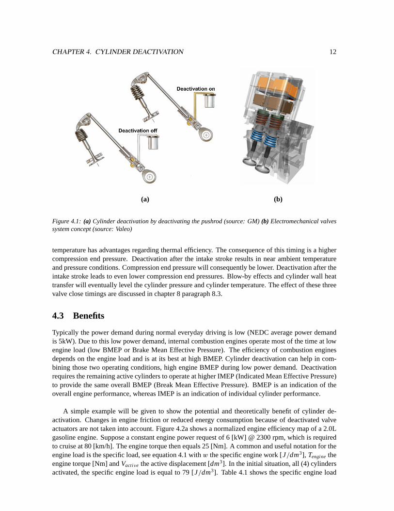
Cylinder deactivation is realized by deactivating (closing) the valves and blocking injector or ignition(Otto-engine) signals. Current cylinder deactivation systems use a mechanical valvetrain, where ahydraulic control element is used to prevent the cam followers from actuating the valve. Figure 4.1ashows a mechanical/hydraulic deactivation mechanism used by General Motors. Future camless val-vetrain systems, figure 4.1b, simplify cylinder deactivation by keeping the valves closed.
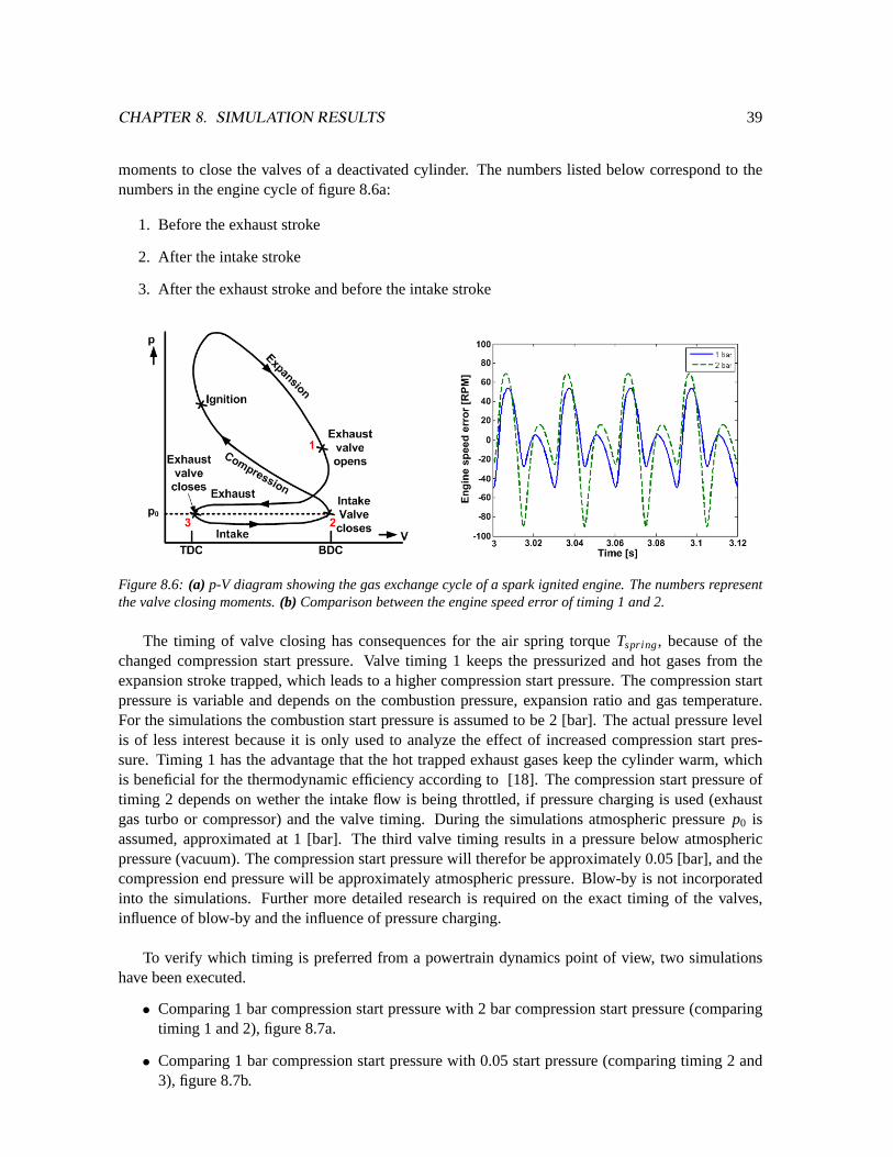
By closing the valves the cylinder is being used as an ”air spring”. This air spring performs aperiodical compression and expansion cycle, which eliminates the pumping losses (apart from blow-by). There are three moments to start the deactivation, before the exhaust stroke, after the intakestroke and after the exhaust stroke. Deactivation before the exhaust stroke results in hot exhaust gasesbeing trapped inside the cylinder. This keeps the cylinder warm and according to [18] this high
11
CHAPTER 4. CYLINDER DEACTIVATION 12
(a) (b)
(a) (b)
Figure 4.1: (a) Cylinder deactivation by deactivating the pushrod (source: GM)(b) Electromechanical valvessystem concept (source: Valeo)
temperature has advantages regarding thermal efficiency. The consequence of this timing is a highercompression end pressure. Deactivation after the intake stroke results in near ambient temperatureand pressure conditions. Compression end pressure will consequently be lower. Deactivation after theintake stroke leads to even lower compression end pressures. Blow-by effects and cylinder wall heattransfer will eventually level the cylinder pressure and cylinder temperature. The effect of these threevalve close timings are discussed in chapter 8 paragraph 8.3.
4.3 Benefits
Typically the power demand during normal everyday driving is low (NEDC average power demandis 5kW). Due to this low power demand, internal combustion engines operate most of the time at lowengine load (low BMEP or Brake Mean Effective Pressure). The efficiency of combustion enginesdepends on the engine load and is at its best at high BMEP. Cylinder deactivation can help in com-bining those two operating conditions, high engine BMEP during low power demand. Deactivationrequires the remaining active cylinders to operate at higher IMEP (Indicated Mean Effective Pressure)to provide the same overall BMEP (Break Mean Effective Pressure). BMEP is an indication of theoverall engine performance, whereas IMEP is an indication of individual cylinder performance.
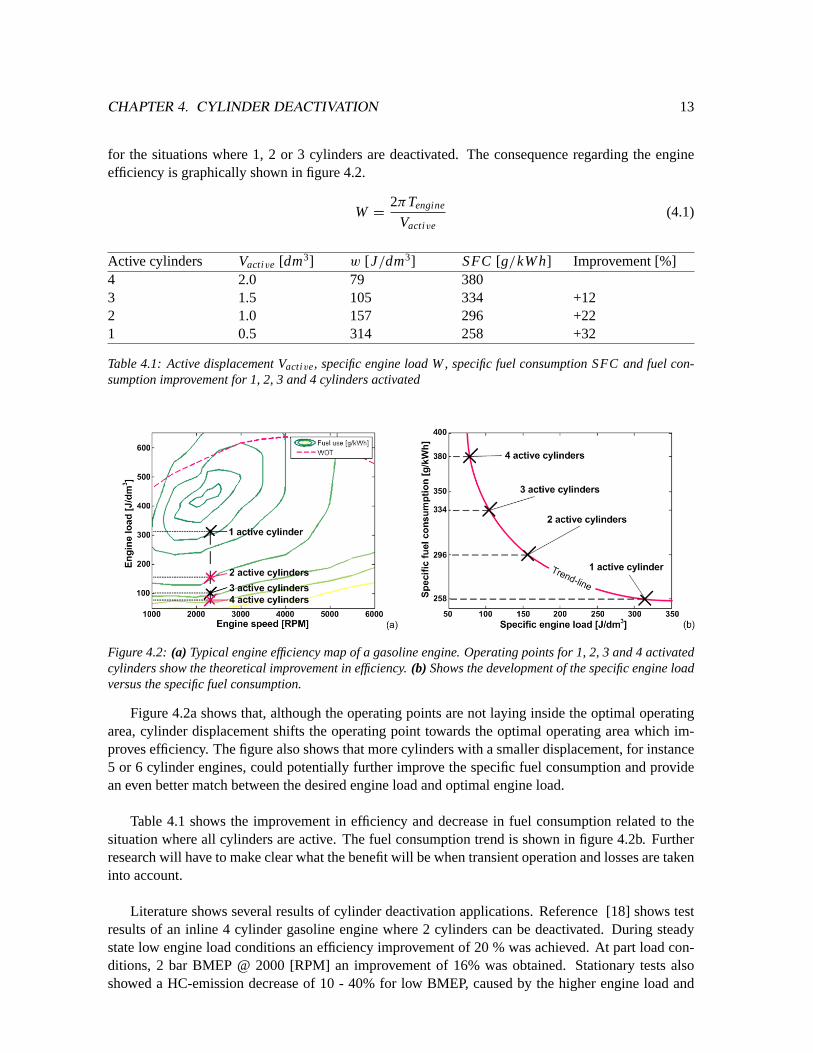
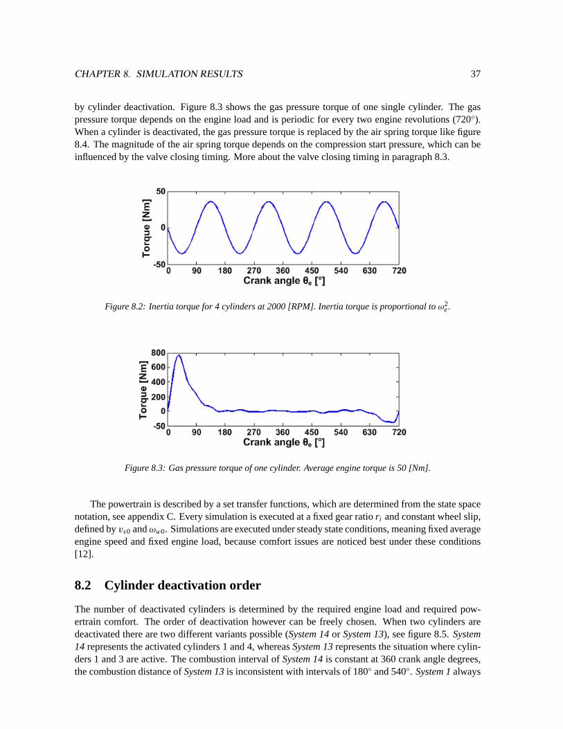
A simple example will be given to show the potential and theoretically benefit of cylinder de-activation. Changes in engine friction or reduced energy consumption because of deactivated valveactuators are not taken into account. Figure 4.2a shows a normalized engine efficiency map of a 2.0Lgasoline engine. Suppose a constant engine power request of 6 [kW] @ 2300 rpm, which is requiredto cruise at 80 [km/h]. The engine torque then equals 25 [Nm]. A common and useful notation for theengine load is the specific load, see equation 4.1 withw the specific engine work [J/dm3], Tenginetheengine torque [Nm] andVactive the active displacement [dm3]. In the initial situation, all (4) cylindersactivated, the specific engine load is equal to 79 [J/dm3]. Table 4.1 shows the specific engine load
CHAPTER 4. CYLINDER DEACTIVATION 13
for the situations where 1, 2 or 3 cylinders are deactivated. The consequence regarding the engineefficiency is graphically shown in figure 4.2.
Table 4.1: Active displacement Vactive, specific engine load W, specific fuel consumption SFC and fuel con-sumption improvement for 1, 2, 3 and 4 cylinders activated
(a) (b)
Figure 4.2: (a) Typical engine efficiency map of a gasoline engine. Operating points for 1, 2, 3 and 4 activatedcylinders show the theoretical improvement in efficiency.(b) Shows the development of the specific engine loadversus the specific fuel consumption.
Figure 4.2a shows that, although the operating points are not laying inside the optimal operatingarea, cylinder displacement shifts the operating point towards the optimal operating area which im-proves efficiency. The figure also shows that more cylinders with a smaller displacement, for instance5 or 6 cylinder engines, could potentially further improve the specific fuel consumption and providean even better match between the desired engine load and optimal engine load.
Table 4.1 shows the improvement in efficiency and decrease in fuel consumption related to thesituation where all cylinders are active. The fuel consumption trend is shown in figure 4.2b. Furtherresearch will have to make clear what the benefit will be when transient operation and losses are takeninto account.
Literature shows several results of cylinder deactivation applications. Reference [18] shows testresults of an inline 4 cylinder gasoline engine where 2 cylinders can be deactivated. During steadystate low engine load conditions an efficiency improvement of 20 % was achieved. At part load con-ditions, 2 bar BMEP @ 2000 [RPM] an improvement of 16% was obtained. Stationary tests alsoshowed a HC-emission decrease of 10 - 40% for low BMEP, caused by the higher engine load and
CHAPTER 4. CYLINDER DEACTIVATION 14
consequently a higher cylinder temperature. At higher BMEP both the fuel consumption and HC-emissions increased slightly due to the reduction of the volumetric efficiency.
Reference [2] reports about a field test with a taxi fleet, using 4 cylinder engines capable of de-activating 2 cylinders. The taxi-drive cycle resulted in fuel consumption reductions of 20 - 30%. A6 cylinder inline engine showed an improvement of 45% in fuel efficiency during idle. During theNEDC-cycle the reduction was 25.4%, both results where obtained with 3 cylinders deactivated.
Finally, the 5.0L V8 engine, as used by Mercedes-Benz, shows a reduction in fuel economy of6.5% during the NEDC-cycle and 10.3% during the American FTP+HW cycle, with 4 cylinders de-activated. For Mercedes-Benz, cylinder deactivation makes it possible to combine high performanceand large cylinder displacement with improved fuel economy.
4.4 Limitations
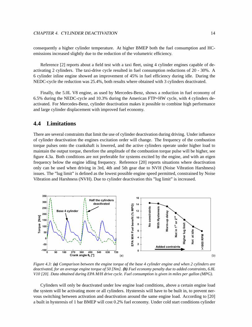
There are several constraints that limit the use of cylinder deactivation during driving. Under influenceof cylinder deactivation the engines excitation order will change. The frequency of the combustiontorque pulses onto the crankshaft is lowered, and the active cylinders operate under higher load tomaintain the output torque, therefore the amplitude of the combustion torque pulse will be higher, seefigure 4.3a. Both conditions are not preferable for systems excited by the engine, and with an eigenfrequency below the engine idling frequency. Reference [20] reports situations where deactivationonly can be used when driving in 3rd, 4th and 5th gear due to NVH (Noise Vibration Harshness)issues. The ”lug limit” is defined as the lowest possible engine speed permitted, constrained by NoiseVibration and Harshness (NVH). Due to cylinder deactivation this ”lug limit” is increased.
(a) (b)
Figure 4.3: (a) Comparison between the engine torque of the base 4 cylinder engine and when 2 cylinders aredeactivated, for an average engine torque of 50 [Nm].(b) Fuel economy penalty due to added constraints, 6.8LV10 [20]. Data obtained during EPA M/H drive cycle. Fuel consumption is given in miles per gallon (MPG).
Cylinders will only be deactivated under low engine load conditions, above a certain engine loadthe system will be activating more or all cylinders. Hysteresis will have to be built in, to prevent ner-vous switching between activation and deactivation around the same engine load. According to [20]a built in hysteresis of 1 bar BMEP will cost 0.2% fuel economy. Under cold start conditions cylinder
CHAPTER 4. CYLINDER DEACTIVATION 15
deactivation may not be possible due to actuator limitations or emission requirements. This delay willalso give a fuel economy penalty. Figure 4.3b shows the reduction in improvement with respect to theconstraints, based on a study performed on a 6.8L V10 gasoline truck engine [20].
The main reason for the failure of cylinder deactivation in the past was the transient control ofthe torque and air/fuel ratio [20]. The introduction of electronic port fuel injection and the electronicthrottle made the re-introduction of cylinder deactivation possible again, as proven by Mercedes-Benz.
Other issues regarding cylinder deactivation are the unbalanced warm-up and cooling of enginecomponents, which could lead to thermal stresses and increased emissions when cooled down cylin-ders are active again. Possible solutions for unbalanced warm-up can be found in frequently reactivat-ing cooled down cylinders and deactivating the warmed up cylinders in order to keep the entire engineequally warmed up. An electronic water pump can also help in balancing the engine temperature byreducing or even reversing the coolant flow direction. Cylinder deactivation also results in changedexhaust flow pulsations and flow. This has implications for the effectiveness of exhaust turbo systemsand catalyst converters.
4.5 Conclusion
In summary, the benefit of cylinder deactivation is threefold. The deactivated cylinders operate as anair spring and therefore do not require pump work, apart from a marginal loss caused by blow-by andheat transfer. Power normally needed to operate the valves is not needed for the deactivated cylinders(holds for both cam driven and camless valvetrain). Therefore the engines mechanical loss is reduced.The third and main benefit is a result of the higher engine load, which results in less pumping losses.
Due to limitations the benefit and effect of Cylinder deactivation on engine efficiency will be re-duced. With an effective NVH suppression method the engines’ efficiency and deactivation time couldbe increased, resulting in reduced fuel consumption. Because of the importance of NVH on cylinderdeactivation the next chapter is devoted to powertrain NVH.
Chapter 5
Powertrain Noise Vibration Harshness
Noise Vibration and Harshness, or NVH, addresses both comfort and durability which are importantrequirements for powertrain design. Cylinder deactivation has an effect on powertrain NVH, becauseof the increased combustion torque amplitude and lowered combustion frequency. Resonances excitedby the engine can cause structures to fail under stress, and therefor will have to be prevented.
This chapter explains what kind of vibration sources are relevant for the powertrain design andwhat the influence of cylinder deactivation will be on these vibrations. There are several systems ormethods to suppress powertrain vibrations. Three systems are discussed which can help in increasingthe powertrain comfort and durability, the torsion damper, dual mass flywheel and the integratedstarter alternator damper.
5.1 Sources of excitation
Powertrain excitation sources can be differentiated into internal and external sources ( [4] and [28]).External excitations can be caused by the driver (pedal tip-in, pedal back-out), by road irregularitiesor by body-powertrain interactions.
Internal excitations are caused by engine excitations and driveline imperfections. An internalcombustion engine is a source of several periodic excitations, depending on the configuration andnumber of cylinders. In general the excitations are caused by the reciprocating engine inertias and bythe combustion torque pulses.
The engines main order of excitation, caused by the combustion pulse torque, can be determinedwith equation 5.1, withNmain [-] the engines main harmonic excitation order,numcyl [-] the numberof cylinders andz[-] the number of revolutions needed for one cylinder to complete one engine cycle(2-stroke = 1; 4-stroke = 2).
Nmain =numcyl
z(5.1)
fex =neNmain
60(5.2)
When cylinders are deactivated the engine orderNmain changes. This has a consequence for theexcitation frequency, which is linear dependant on the engine order. Equation 5.2 shows the excitation
frequencyfex [Hz] with the main orderNmain and engine speedne [RP M].
Driveline imperfections are caused by gear imperfections, driveshaft misalignment, imperfect uni-versal joints or unbalanced rotating inertias. Discussing these causes of excitations lies beyond thescope of this report, because there is no relation between cylinder deactivation and these imperfec-tions.
5.2 Response
The main vibration response is the deceleration and acceleration of the crankshaft, caused by theintermitting combustion torque pulses and inertia torque. This torsional vibration can:
• be transferred to the transmission primary shaft, where the angular acceleration causes gearrattle [12]
• cause a longitudinal vehicle accelerating called vehicle shuffle .
• cause the powertrain unit, engine block and transmission housing, to shake with respect to thevehicle body [4].
Vehicle shuffle and engine shaking are of direct influence on the comfort of the occupants. Gearrattle is caused by engine torque fluctuations, resulting in vibration of the lightly loaded components inthe gearbox, such as the idler gears, synchronizer rings and sliding sleeves. Transmission of vibrationfrom the gear shafts through bearings to the gearbox housing is the principal mechanism, radiatingnoise to the environment. During cylinder deactivation the firing distance will change, causing theengine sound to change also. This phenomena will be one of the major hurdles to get cylinder deacti-vation accepted by the ”market”.
Acceptable maximum values for gear rattle, vehicle shuffle and engine shaking are hard to give,because they highly depend on the occupants personal perception. Furthermore, interior damping,vehicle body structure, engine mounts and even sound deadening will dampen the vibrations whichmakes it hard to quantify the maximum allowable vibrations emitted by the powertrain.
Resonance occurs when the excitation frequency happens to be near or exactly on the systemseigen frequencies. Excitation with the eigen frequency will result in a rising amplitude which, whennot dampened, will lead to destruction of the structure or system.
5.3 Comfort improvement solutions
Solutions for powertrain NVH problems can be categorized as followed:
Reduce or eliminate the source causing the vibrationReducing or eliminating the vibration source can be obtained by increasing the number of cylinders,which results in lower and more frequent combustion torque pulses. This solution is opposite to cylin-der deactivation and therefor leads to opposite effects.
Isolation of the sourceIsolation of the source can be done by decoupling the internal combustion engine from the vehicles’
wheels. This can be obtained by a series hybrid setup, where the combustion engine drives a gener-ator and a motor drives the wheels. The combustion torque pulses and inertia torque are no longertransmitted through the transmission to the wheels. The series hybrid setup will be covered in anotherthesis [6].
Tuning of the systemTuning of the system can be done by changing the parameters of the powertrain, like inertia or stiff-ness. Tuning can help in shifting the systems eigenfrequencies away from the excitation frequencies,eliminating the possibility of resonances.
Damping of the sourceThere are several systems available to dampen the vibration source caused by the engine. The mostcommon method to dampen torsional vibrations, in European cars, is by means of a Torsion Damper(TD) integrated into the clutch assembly. Vehicles in the upper segment or with diesel and turbo en-gines are equipped with a Dual Mass Flywheel (DMF), also to dampen the torsional vibrations. TheIntegrated Starter Alternator Damper (ISAD) is currently not yet applied to a mass produced vehicle.Besides the vibration damper function, the ISAD system has other beneficial functions making it anuseful addition to the powertrain, see paragraph 5.3.3.
5.3.1 Torsion damper
A torsion damper (TD) is used to isolate the rotational vibrations from the engine to the transmission.Often it is integrated into a dry plate clutch, as used in manual transmissions, see figure 5.1a. Smallcoil springs transfer the engine torque from the friction elements to the transmission primary shaft.
The TD coil spring stiffness creates an extra powertrain resonance frequency, typically between 40- 80 [Hz] (equals 1200 - 2400 [RPM] for a 4 cylinder 4 stroke engine). This resonance frequency lieswithin the operating speed range. It is possible to lower the eigen frequency by lowering the springstiffness and/or by increasing the transmission inertia. However, a too low spring stiffness causes thesprings to block under heavy load, resulting in a rigid connection.
(a) (b)
(a) (b)
Figure 5.1: (a) Schematic representation of the torsion damper.(b) Schematic representation of the dual massflywheel.
The Dual Mass Flywheel (DMF) is applied more and more in luxury vehicles and is finding its wayinto the turbo(diesel) engine market. A DMF flywheel consists of two inertias, connected to eachother by a spring-damper system. One inertia contributes to the engine inertia, the second inertiacontributes to the transmission inertia in case the clutch is closed. Due to packaging the used coilspring can be longer compared to the TD which results in a lower spring stiffness and a powertrainresonance frequency which is shifted below engine idle speed. The now lowered eigen frequencycauses problems during cranking of the engine, see [3] and [5]. The amplitude of the lowered eigenfrequency is also typically higher. The application of a DMF comes with a penalty in weight, volumeand cost [32].
5.3.3 Integrated starter alternator damper
The Integrated Starter Alternator Damper (ISAD) is an active damping system as opposed to passivesystems as the TD and DMF. The ISAD system is not used to shift resonance frequencies, but is usedto dampen the vibration amplitudes. The ISAD system will replace the alternator, starter motor andflywheel with one system, mounted directly onto the crankshaft. Mechanically the ISAD system isrepresented by a rotor, mounted onto the crankshaft and a stator mounted to the engine block. Typi-cally the rotor inertia is lower than the flywheel inertia it replaces.
The damper function is used to slow down the crankshaft when it is accelerated under influenceof a torque pulse. By slowing down the crankshaft the alternator is generating electrical energy whichcan be accumulated temporarily into a capacitor. At the next compression cycle the accumulated en-ergy is used to accelerate the crankshaft if it is rotating too slow. This results in a lower engine speedfluctuation, which in turn reduces engine shake, gear rattle and vehicle shuffle.
Besides its torsional damping function, the ISAD system has several features which makes it de-sirable in future powertrains. Current alternator systems can produce up to 2.5 [kW] of electricalpower, limited by the belt drive. Increasing demand of electric power consumers like electric pumpsand in car entertainment systems demands a higher alternator output [14], which cannot be obtainedefficiently any more with the current state of art belt driven alternators [24]. The ISAD system isable to generate a higher power output at a higher electrical efficiency, at the same time increasing thevehicles system voltage from 14V to 42V.
The higher system voltage and power availability makes camless valve actuation technology possi-ble, further improving engine efficiency. Belt driven accessoires can be replaced by pump-on-demandsystems, by doing so reducing parasitic losses and provide freedom in the engine auxiliary packageof the engine.
The use of pump-on-demand has another advantage, related to NVH. The stand alone pumps arenot driven by the crankshaft anymore and therefor are easier to dampen. Pump systems can now betested and designed separately from the engine, which can reduce cost in testing and simulation ormake modularity possible. Electrically heated catalytic converters lower the light off time, reducingcold start exhaust emissions which are currently a major contributor to total exhaust emissions. It alsocould enable the use of cylinder deactivation directly after cold starts. Typical hybrid functions asstart/stop, boosting and regenerative braking are possible as already mentioned in chapter 3.
Engine shake, vehicle shuffle and gear rattle are the three main parameters which define powertraincomfort. These parameters will therefor be used to analyze the effect of cylinder deactivation. Thereare several systems available to improve the vibrational behavior of powertrains, because of the ad-ditional functions the ISAD system is preferred. The next chapter describes two powertrain modelswhich will be used to analyze the effect of cylinder deactivation. A powertrain equipped with a torsiondamper will function as a benchmark, while the powertrain containing the ISAD system will representthe desired powertrain.
Chapter 6
Powertrain model
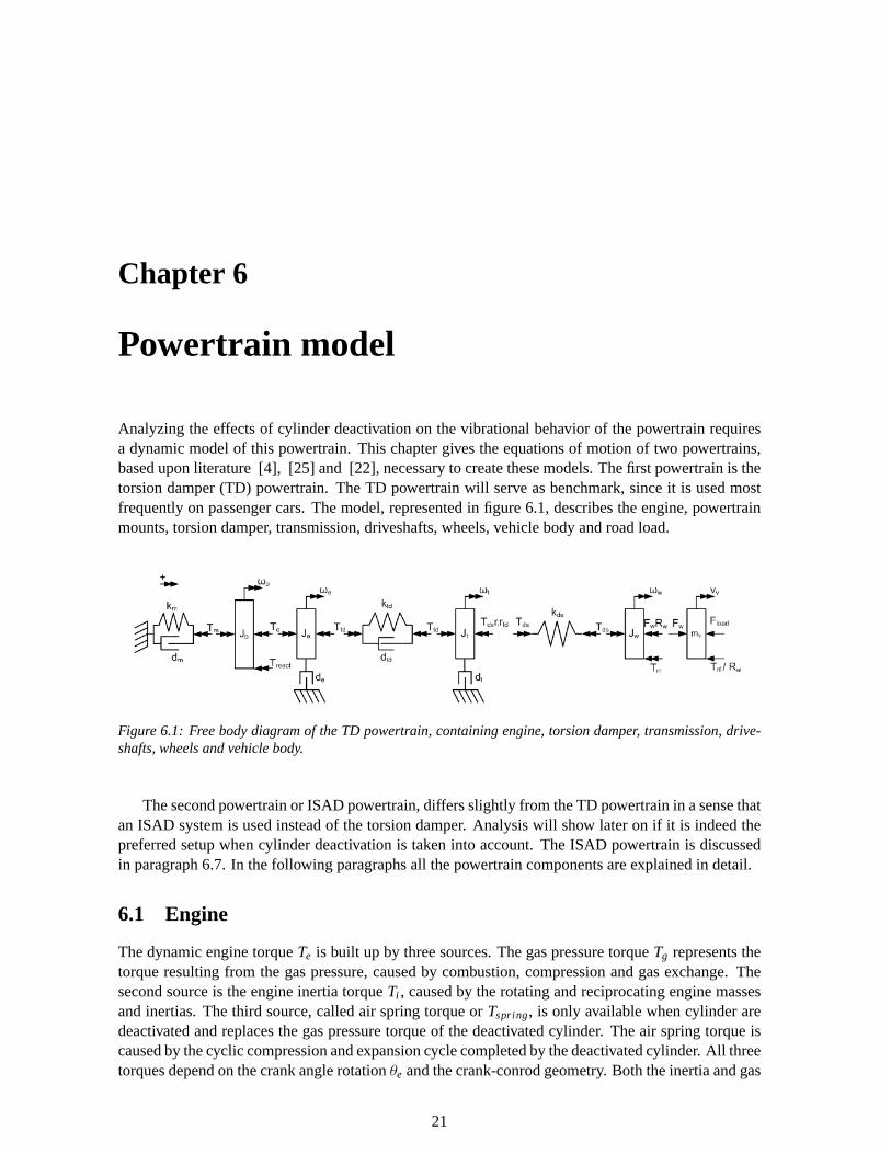
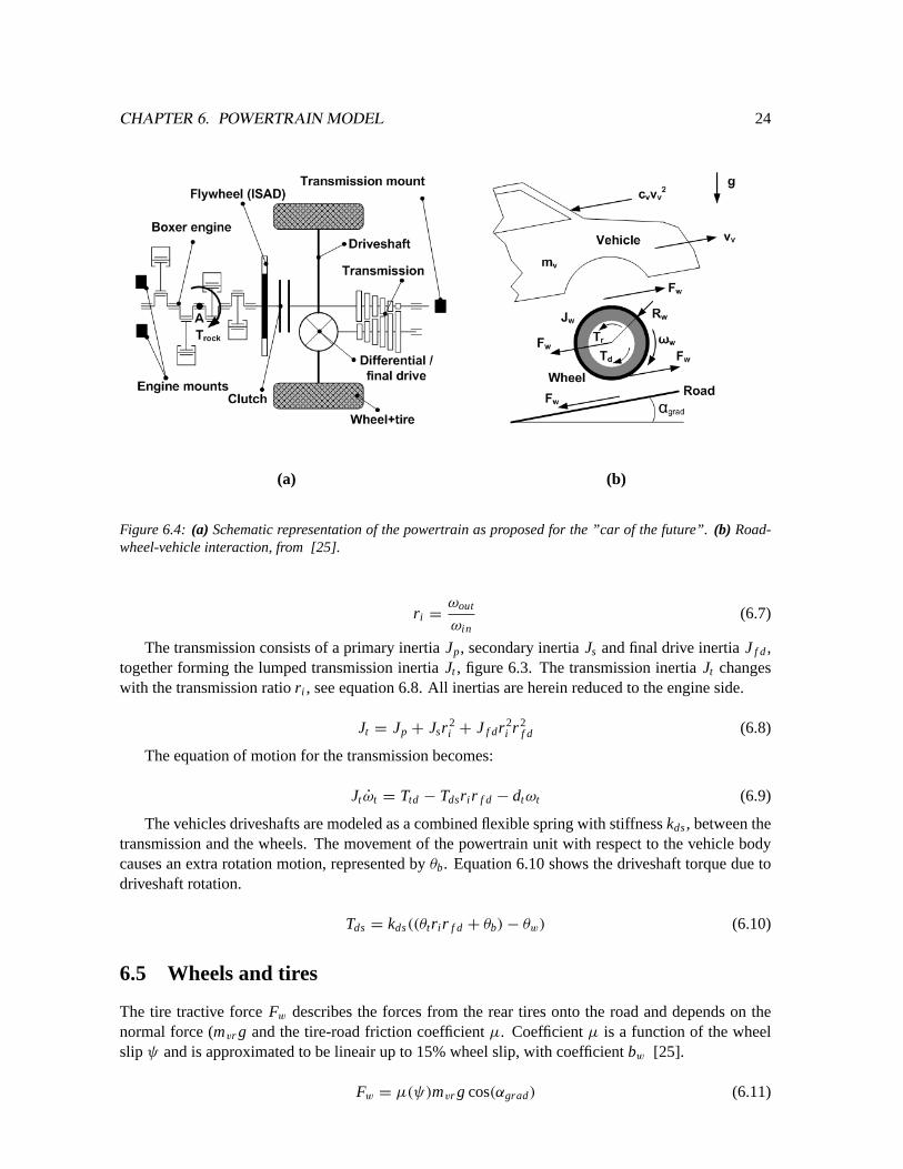
Analyzing the effects of cylinder deactivation on the vibrational behavior of the powertrain requiresa dynamic model of this powertrain. This chapter gives the equations of motion of two powertrains,based upon literature [4], [25] and [22], necessary to create these models. The first powertrain is thetorsion damper (TD) powertrain. The TD powertrain will serve as benchmark, since it is used mostfrequently on passenger cars. The model, represented in figure 6.1, describes the engine, powertrainmounts, torsion damper, transmission, driveshafts, wheels, vehicle body and road load.
Figure 6.1: Free body diagram of the TD powertrain, containing engine, torsion damper, transmission, drive-shafts, wheels and vehicle body.
The second powertrain or ISAD powertrain, differs slightly from the TD powertrain in a sense thatan ISAD system is used instead of the torsion damper. Analysis will show later on if it is indeed thepreferred setup when cylinder deactivation is taken into account. The ISAD powertrain is discussedin paragraph 6.7. In the following paragraphs all the powertrain components are explained in detail.
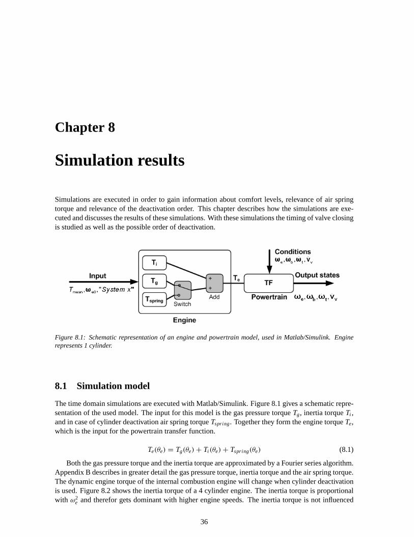
6.1 Engine
The dynamic engine torqueTe is built up by three sources. The gas pressure torqueTg represents thetorque resulting from the gas pressure, caused by combustion, compression and gas exchange. Thesecond source is the engine inertia torqueTi , caused by the rotating and reciprocating engine massesand inertias. The third source, called air spring torque orTspring, is only available when cylinder aredeactivated and replaces the gas pressure torque of the deactivated cylinder. The air spring torque iscaused by the cyclic compression and expansion cycle completed by the deactivated cylinder. All threetorques depend on the crank angle rotationθe and the crank-conrod geometry. Both the inertia and gas
21
CHAPTER 6. POWERTRAIN MODEL 22
pressure torque are modeled by a Fourier algorithm. A detailed explanation about the gas pressure,inertia and air spring torque can be found in appendix B. The influence of the engine geometry onthe engine vibrations will not be studied. Engine frictionde is assumed to be lineair dependant onthe engine speedωe [1]. The total engine torque reduced by the engine friction and engine loadTtd
causes the engine inertiaJe to accelerate or decelerate. The equation of motion is given by equation6.2.
Te(θe) = Tg(θe)+ Ti (θe)+ Tspring(θe) (6.1)
Jeωe = Te − Ttd − deωe (6.2)
6.2 Powertrain mounts
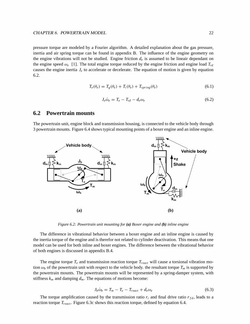
The powertrain unit, engine block and transmission housing, is connected to the vehicle body through3 powertrain mounts. Figure 6.4 shows typical mounting points of a boxer engine and an inline engine.
The difference in vibrational behavior between a boxer engine and an inline engine is caused bythe inertia torque of the engine and is therefor not related to cylinder deactivation. This means that onemodel can be used for both inline and boxer engines. The difference between the vibrational behaviorof both engines is discussed in appendix B.4.
The engine torqueTe and transmission reaction torqueTreact will cause a torsional vibration mo-tionωb of the powertrain unit with respect to the vehicle body. the resultant torqueTm is supported bythe powertrain mounts. The powertrain mounts will be represented by a spring-damper system, withstiffnesskm and dampingdm. The equations of motions become:
Jbωb = Tm − Te − Treact + deωe (6.3)
The torque amplification caused by the transmission ratior i and final drive ratior f d, leads to areaction torqueTreact. Figure 6.3c shows this reaction torque, defined by equation 6.4.
CHAPTER 6. POWERTRAIN MODEL 23
Treact = Ttd(1
r i r f d− 1) (6.4)
The powertrain unit mount is defined with equation 6.5.
Tm = −kmθb − dmωb (6.5)
6.3 Clutch
The ”car of the future” is equipped with a 6 speed automated manual transmission (AMT). A dryplate clutch is used to decouple the engine from the transmission during shifting. Three operatingmodes can be distinguished, open clutch, slipping clutch and a fully closed clutch. Ratio changes arenot included in the cylinder deactivation analysis, therefor the fully closed clutch state is of interest,consequently simplifying the model in terms of DOF. Under closed conditions the engine and clutchare considered as a rigid system.
6.3.1 Torsion Damper
Manual transmissions are normally equipped with an torsion damper (TD) integrated into the clutchplate. The TD’s main function is to isolate the transmission from the engine periodic vibrations asexplained in paragraph 5.3.1. The TD is represented by a spring-damper system, with spring stiffnessktd and damper constantdtd. The movement of the powertrain unit with respect to the vehicle bodycauses an extra rotation motion, represented byθb andωb. A schematic representation of the TD ispictured in figure 6.3.
Figure 6.3: (a) Schematic representation of the torsion damper.(b) Schematic representation of the lumpedtransmission model, build up by primary shaft Jp, secondary shaft Js and final drive / differential inertia Jf d.(c) Schematic representation of the reaction torque of the powertrain unit.
6.4 Transmission and driveshaft
The powertrain concept is based on a automated manual transmission (AMT) with a combined finaldrive / differential unit. The transmission ratior i is defined by equation 6.7, with indexi indicatingthe selected gear while the final drive ratio is defined byr f d. The transmission frictiondt is assumedto be linear dependant on the speedωt of the primary transmissions shaft [26].
CHAPTER 6. POWERTRAIN MODEL 24
(a) (b)
(a) (b)
Figure 6.4: (a) Schematic representation of the powertrain as proposed for the ”car of the future”.(b) Road-wheel-vehicle interaction, from [25].
r i =ωout
ωin(6.7)
The transmission consists of a primary inertiaJp, secondary inertiaJs and final drive inertiaJ f d,together forming the lumped transmission inertiaJt , figure 6.3. The transmission inertiaJt changeswith the transmission ratior i , see equation 6.8. All inertias are herein reduced to the engine side.
Jt = Jp + Jsr2i + J f dr 2
i r 2f d (6.8)
The equation of motion for the transmission becomes:
Jt ωt = Ttd − Tdsr i r f d − dtωt (6.9)
The vehicles driveshafts are modeled as a combined flexible spring with stiffnesskds, between thetransmission and the wheels. The movement of the powertrain unit with respect to the vehicle bodycauses an extra rotation motion, represented byθb. Equation 6.10 shows the driveshaft torque due todriveshaft rotation.
Tds = kds((θtr i r f d + θb)− θw) (6.10)
6.5 Wheels and tires
The tire tractive forceFw describes the forces from the rear tires onto the road and depends on thenormal force (mvr g and the tire-road friction coefficientµ. Coefficientµ is a function of the wheelslipψ and is approximated to be lineair up to 15% wheel slip, with coefficientbw [25].
Fw = µ(ψ)mvr g cos(αgrad) (6.11)
CHAPTER 6. POWERTRAIN MODEL 25
µ(ψ) = bwψ (6.12)
Wheel slip is necessary to translate the forces from the tire to the road and visa versa. The wheelslip for driving wheels is defined by equation 6.13.
ψ = 1 −vv
ωwRw(6.13)
Rolling resistance acts on both the front (Tr f ) and rear (Trr ) wheels and depends on the normalforce and the tire deformation lengthxl .
Tr f = xl mv f g cosαgrad (6.14)
Trr = xl mmrg cosαgrad (6.15)
The equation of motion for the rear wheels become:
2Jwωw = Tds − FwRw − Trr (6.16)
The front wheels have no contribution regarding traction, due to the rear wheel drive concept. Thefront wheels are therefor regarded as simple inertias causing drag due to rolling resistance. In orderto reduce the models DOF, the inertias of the front wheels are added to the vehicle mass, as shown inequation 6.17.
mlumped = mv +2JwR2w
(6.17)
6.6 External load
The previous paragraph already discussed the rolling resistanceTr . Together with the air resistanceand gradient resistance they form the external vehicle load. Air resistanceFair is defined accordingto:
Fair = cvv2v (6.18)
The air resistance constantcv is defined by:
cv =1
2ρair cd Av (6.19)
Herein isρair the air density,cd the vehicles drag coefficient,Av the frontal area of the vehicleandvv the vehicle speed.
The gradient load depends on the vehicle weight and the road gradientαgrad.
Fgrad = mvg sinαgrad (6.20)
The total external vehicle load becomes:
Fload = Fair + Fgrad (6.21)
With this the equation of motion regarding the vehicle dynamics becomes:
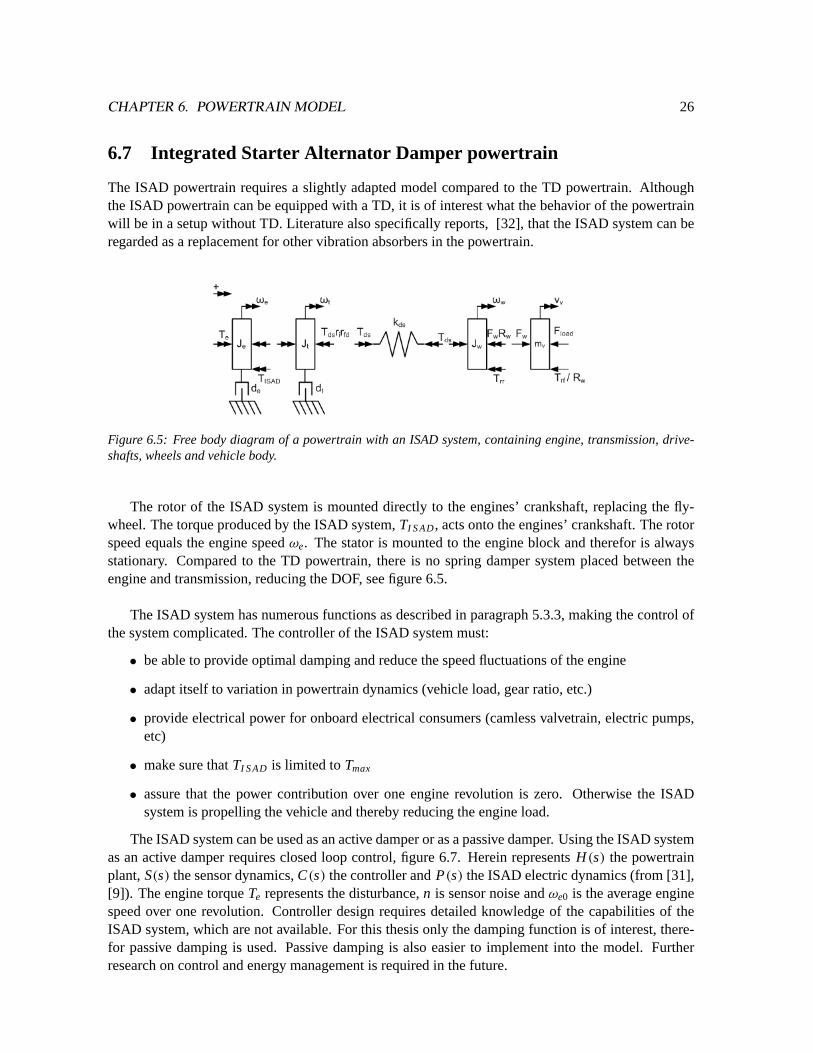
The ISAD powertrain requires a slightly adapted model compared to the TD powertrain. Althoughthe ISAD powertrain can be equipped with a TD, it is of interest what the behavior of the powertrainwill be in a setup without TD. Literature also specifically reports, [32], that the ISAD system can beregarded as a replacement for other vibration absorbers in the powertrain.
Figure 6.5: Free body diagram of a powertrain with an ISAD system, containing engine, transmission, drive-shafts, wheels and vehicle body.
The rotor of the ISAD system is mounted directly to the engines’ crankshaft, replacing the fly-wheel. The torque produced by the ISAD system,TI S AD, acts onto the engines’ crankshaft. The rotorspeed equals the engine speedωe. The stator is mounted to the engine block and therefor is alwaysstationary. Compared to the TD powertrain, there is no spring damper system placed between theengine and transmission, reducing the DOF, see figure 6.5.
The ISAD system has numerous functions as described in paragraph 5.3.3, making the control ofthe system complicated. The controller of the ISAD system must:
• be able to provide optimal damping and reduce the speed fluctuations of the engine
• adapt itself to variation in powertrain dynamics (vehicle load, gear ratio, etc.)
• provide electrical power for onboard electrical consumers (camless valvetrain, electric pumps,etc)
• make sure thatTI S AD is limited toTmax
• assure that the power contribution over one engine revolution is zero. Otherwise the ISADsystem is propelling the vehicle and thereby reducing the engine load.
The ISAD system can be used as an active damper or as a passive damper. Using the ISAD systemas an active damper requires closed loop control, figure 6.7. Herein representsH(s) the powertrainplant,S(s) the sensor dynamics,C(s) the controller andP(s) the ISAD electric dynamics (from [31],[9]). The engine torqueTe represents the disturbance,n is sensor noise andωe0 is the average enginespeed over one revolution. Controller design requires detailed knowledge of the capabilities of theISAD system, which are not available. For this thesis only the damping function is of interest, there-for passive damping is used. Passive damping is also easier to implement into the model. Furtherresearch on control and energy management is required in the future.
CHAPTER 6. POWERTRAIN MODEL 27
Figure 6.6: Maximum torque characteristic and efficiency map of a starter generator system (fromADV I SO RT M Honda Insight data). Positive torque is motor mode, negative torque is generator mode.
The damping values are chosen in such a way thatTI S AD never exceeds the maximum torque val-ues as shown in figure 6.6. The result and effect of the ISAD system depends highly on the torquecapacity of the starter generator. The used maximum torque data is taken from the 10 [kW] starteralternator system of the Honda Insight mild hybrid vehicle, which has the same parallel hybrid pow-ertrain setup as required for the ”car of the future”. The reaction time of the ISAD system is assumedto be infinite fast, while sensor dynamics are not taken into account. The damper is only used to provethe concept of damping vibrations caused by cylinder deactivation, therefor the system dynamics areneglected for now.
The engine and transmission inertia are lumped because of the removed torsion damper withrespect to the TD powertrain. The ISAD torque depends on the variable damper constantdisad(ωe0, r i )
and the engine speed error(ωe(t)−ωe0). Because the engine speed error depends on the transmissionratio and engine speed, the damping is also ratio and engine speed specific.
TI S AD = (ωe(t)− ωe0)disad(ωe0, r i ) (6.23)
ωe = ωt (6.24)
The engines’ equation of motion for the ISAD powertrain changes from 6.2 to:
(Je + Jt)ωe = Te − Tds − (de + dt)ωe − TI S AD (6.25)
CHAPTER 6. POWERTRAIN MODEL 28
Figure 6.7: Block diagram of the closed loop active damping using controller C(s).
6.8 Conclusion
Two powertrain setups, the TD powertrain and the ISAD powertrain, are described in detail. Theequations of motion can be used to make numerical models of the powertrains, see appendix C. Withthese models frequency and time domain simulations can be executed to analyze the effect of cylinderdeactivation on powertrain vibrations. The ISAD powertrain uses a starter alternator as vibrationdamper instead of a torsion damper. The ISAD system has been modeled as a simple passive damper.Sensor and ISAD system dynamics are not taken into account in order to simplify the models. Furtherresearch on controllers and energy management is necessary to integrate the damper function withother hybrid functions.
Chapter 7
Frequency domain response
Deactivation of cylinders causes the engines’ excitation frequency to change, possibly interfering withthe powertrains resonance frequency. A frequency response gives information about resonances andmagnitudes at certain excitation frequencies. Excitation frequencies around the eigen frequency ofthe powertrain must be prevented, because resonances can cause fatigue, wear or immediate damageof powertrain components.
The previous chapter described two different powertrain setups, the TD powertrain and the ISADpowertrain. Frequency analysis will show which powertrain is best suited for cylinder deactivationand what can be done to improve the powertrain behavior.
7.1 State space model
In order to obtain the frequency response plots, a state space model is made with the powertrain modelsfrom the previous chapter. The TD powertrain is described by 8 linear and non-linear differentialequations, whereas the ISAD powertrain is described by 6 linear and non-linear differential equations.The system is linearized around stationary points of interest, meaning engine speed and fixed gearratio. The steps of the linearization process are described in detail in appendix C. The system statesand input vector are shown below for the TD powertrain, equation 7.1:
x = [ωb.Tm, ωe, Ttd, ωt , Tds, ωw, vv]T
y = [Te]
(7.1)
And for the ISAD powertrain, equation 7.2:
x = [ωb, Tm, ωe, Tds, ωw, vv]T
y = [Te]
(7.2)
29
CHAPTER 7. FREQUENCY DOMAIN RESPONSE 30
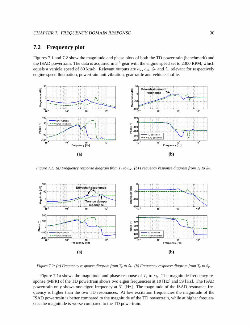
7.2 Frequency plot
Figures 7.1 and 7.2 show the magnitude and phase plots of both the TD powertrain (benchmark) andthe ISAD powertrain. The data is acquired in 5th gear with the engine speed set to 2300 RPM, whichequals a vehicle speed of 80 km/h. Relevant outputs areωe, ωb, ωt and vv relevant for respectivelyengine speed fluctuation, powertrain unit vibration, gear rattle and vehicle shuffle.
(a) (b)
(a) (b)
Figure 7.1: (a) Frequency response diagram from Te toωe. (b) Frequency response diagram from Te to ωb.
(a) (b)
(a) (b)
Figure 7.2: (a) Frequency response diagram from Te to ωt . (b) Frequency response diagram from Te to vv.
Figure 7.1a shows the magnitude and phase response ofTe to ωe. The magnitude frequency re-sponse (MFR) of the TD powertrain shows two eigen frequencies at 10 [Hz] and 59 [Hz]. The ISADpowertrain only shows one eigen frequency at 31 [Hz]. The magnitude of the ISAD resonance fre-quency is higher than the two TD resonances. At low excitation frequencies the magnitude of theISAD powertrain is better compared to the magnitude of the TD powertrain, while at higher frequen-cies the magnitude is worse compared to the TD powertrain.
CHAPTER 7. FREQUENCY DOMAIN RESPONSE 31
Figure 7.1b shows the magnitude and phase response ofTe to ωb. The MFR response of the ISADpowertrain is lower at low frequencies, but higher at frequencies over 13 [Hz]. After the driveshaftresonance at 30 [Hz], the magnitude of the ISAD response drops below the TD response. At frequen-cies above 100 [Hz] both powertrains show an equal response. Both the TD powertrain and ISADpowertrain show a eigenfrequency at 5 [Hz]. This frequency can be checked by using equation 7.3.This eigen frequency is visible in all frequency responses and is equal for all gear ratios.
fmount =1
2π
√km
Jb(7.3)
The response ofTe to ωt can be seen in figure 7.2a. Again, the MFR of the TD powertrain is lowerat high frequencies, providing better vibration suppression. The MFR and PFR ofTe to ωt is equal toTe to ωe because the engine and transmission are coupled to each other in case of a closed clutch.
Figure 7.2b shows the MFR and PFR ofTe to vv. Equally toTe to ωe andTe to ωt the TD pow-ertrain proves to be better at higher frequencies. All four TD plots show two resonance frequencies.The meaning of the first and second resonance frequencies are explained in the next paragraphs.
Powertrain parameters like gear ratio, enlarged engine inertia or changed vehicle load have aneffect on the resonance frequencies and on the shape of the response. The influence of parameterchanges on the transfer function is discussed in appendix E.
7.2.1 1st resonance frequency
Both the TD and ISAD powertrain show a resonance frequency as a result of the driveshaft stiffnesskds. Figure 7.3 represents the simplified undamped TD powertrain model with 3 DOF, withJload asthe total equivalent vehicle inertia,Je the total engine inertia andJt the lumped transmission inertia.Clearly visible is the opposite motion ofJload with respect toJe. Jt has only a small motion in thesame direction asJload and is almost stationary with respect toJe during this resonance frequency.
Figure 7.3: (left) 3D representation of the1st resonance eigen mode (driveshaft resonance)of the TD power-train, (right) schematic representation where the vibration is represented as a vertical vibration motion
The simplified undamped ISAD powertrain, figure 7.4, shows that the combined vehicle inertiaJload moves in the same direction as the lumped engine inertia. The first resonance (or in case of theISAD powertrain the only resonance) is also known as ”driveshaft resonance” [4].
CHAPTER 7. FREQUENCY DOMAIN RESPONSE 32
Figure 7.4: (left) 3D representation of the only resonance eigen mode (driveshaft resonance)of the ISAD pow-ertrain, (right) schematic representation where the vibration is represented as a vertical vibration motion
7.2.2 2nd resonance frequency
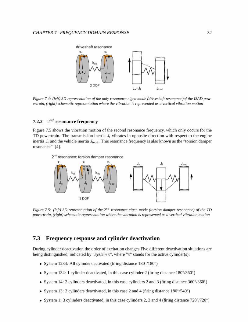
Figure 7.5 shows the vibration motion of the second resonance frequency, which only occurs for theTD powertrain. The transmission inertiaJt vibrates in opposite direction with respect to the engineinertia Je and the vehicle inertiaJload. This resonance frequency is also known as the ”torsion damperresonance” [4].
Figure 7.5: (left) 3D representation of the2nd resonance eigen mode (torsion damper resonance) of the TDpowertrain, (right) schematic representation where the vibration is represented as a vertical vibration motion
7.3 Frequency response and cylinder deactivation
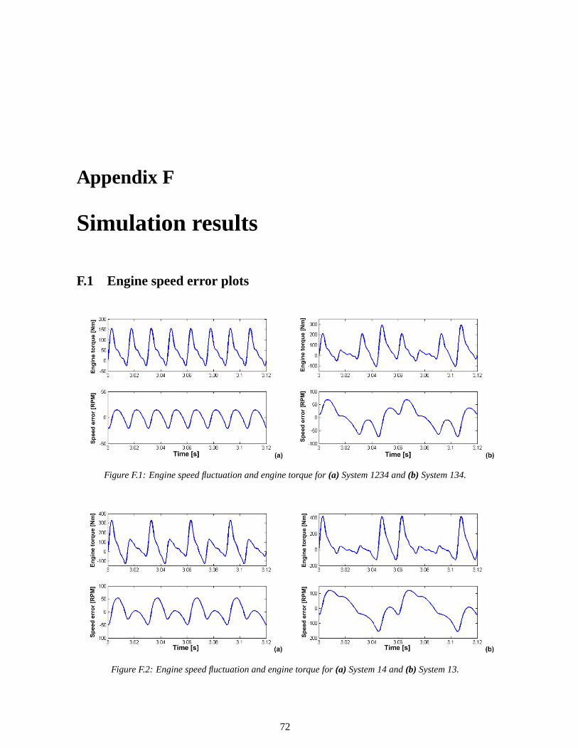
During cylinder deactivation the order of excitation changes.Five different deactivation situations arebeing distinguished, indicated by ”System x”, where ”x” stands for the active cylinder(s):
• System 1234: All cylinders activated (firing distance 180◦/180◦)
• System 134: 1 cylinder deactivated, in this case cylinder 2 (firing distance 180◦/360◦)
• System 14: 2 cylinders deactivated, in this case cylinders 2 and 3 (firing distance 360◦/360◦)
• System 13: 2 cylinders deactivated, in this case 2 and 4 (firing distance 180◦/540◦)
• System 1: 3 cylinders deactivated, in this case cylinders 2, 3 and 4 (firing distance 720◦/720◦)
CHAPTER 7. FREQUENCY DOMAIN RESPONSE 33
System 134represents all combinations where one cylinder is deactivated (System 124, System123, System 234etc.), the resulting engine torque is equal in all cases. This also holds forSystem1, which represents all combinations where 3 cylinders are deactivated. Deactivation of 2 cylinderscan be obtained withSystem 14(constant firing distance of 360◦/360◦) or with System 13(alternatingfiring distance of 180◦/540◦), which results in a different engine torque, as can be seen in figure D.2.
Table 7.1 shows the main engine order for situations where cylinders are deactivated. The ordersare obtained from frequency analysis of the engine torque during deactivation, see figures D.1 to D.3in appendix D. The transmission ratios are dimensioned in such a way that the engine can be operatedwithin an engine speed range of 1700 - 2500 [RPM]. Within this engine speed range the efficiency ofthe engine is potentially the best (although engine specific). Chapter 8 will show what will happenwhen the engine is operated outside this engine speed range. With equation 7.4 the main engine orderscan be translated to excitation frequency when the optimal engine speed range is taken into account.Assumed is that during acceleration up to 1700 [RPM] all cylinders are activated in order to producesufficient power. All system show 2nd and 4th engine orders, caused by the engines’ inertia torque.
Active cylinders(”System x”)
Main engine order(s) -Nmain
fex [Hz] @ 1700[RPM]
fex [Hz] @ 2500[RPM]
System1234 2 57 83System134 1
2, 1, 2 14 83System14 1, 2 28 83System13 1
2, 112, 2 14 83
System1 12, 11
2, 2 14 83
Table 7.1: The table shows the main engine orders for every deactivation system. The lowest excitation ordercorresponds to a minimal excitation frequency at 1700 [RPM].
fex =neNmain
60(7.4)
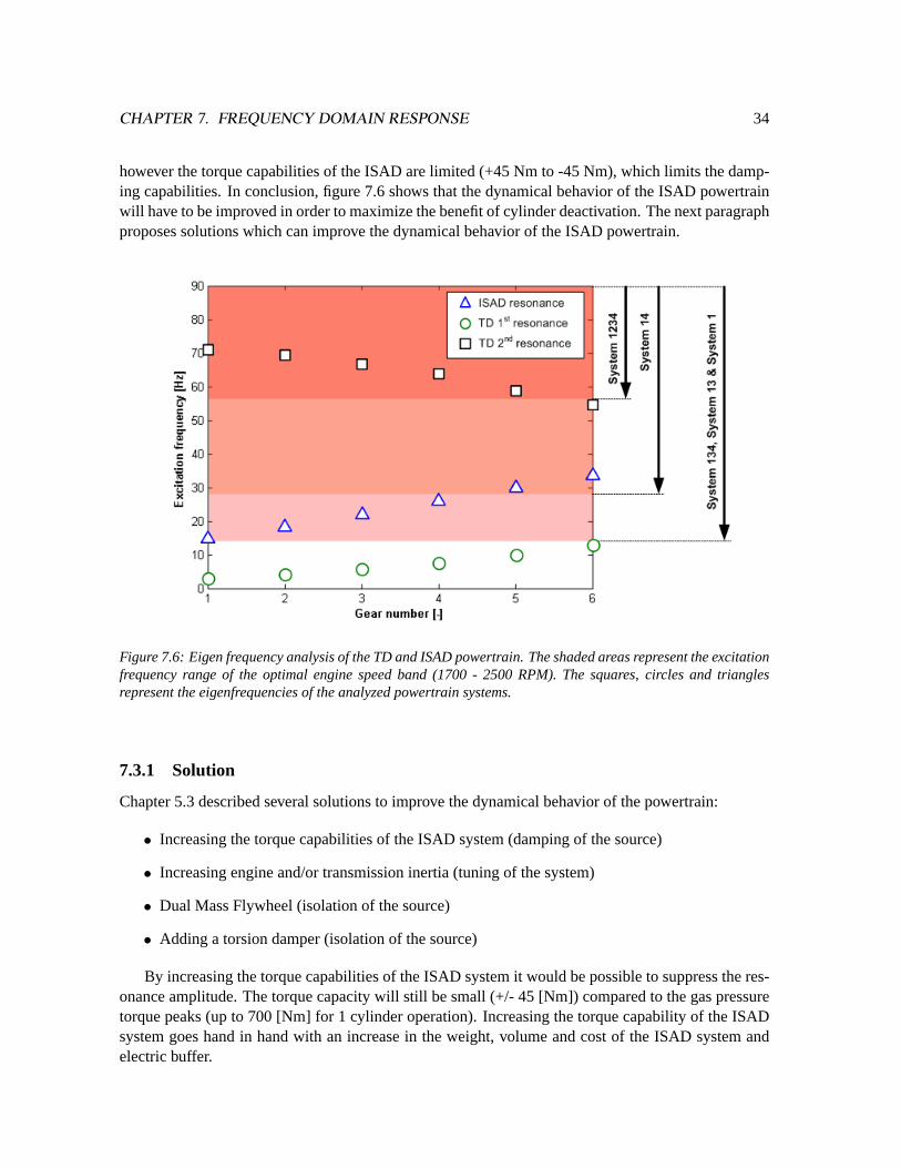
When analyzing the frequency response of the TD and ISAD powertrain, figures 7.1 and 7.2, itbecomes clear that the driveshaft resonance frequency of the ISAD powertrain lies within the engineexcitation frequency range during deactivation of 1, 2 or 3 cylinders.
Figure 7.6 is the result of combining all resonance frequencies and engine excitation frequenciesinto one graph. The overlapping colored areas represent the excitation frequency range caused bycylinder deactivation. For example, the lowest main engine order forSystem 1is 1
2, which means thatthe excitation frequency is equal to 14 [Hz] at 1700 [RPM]. The figure also shows the resonance fre-quencies of the ISAD powertrain (triangles) and TD powertrain (1st resonance = circles, 2nd resonance= squares). The driveshaft resonance frequency of the ISAD powertrain lays within the excitation fre-quency range during 1, 2 and 3 deactivated cylinders. The second resonance of the TD powertrainalso lies within the operating range, however as figures 7.1 to 7.2 show, the TD powertrain showslower magnitudes at higher frequencies compared to the ISAD powertrain. The first TD resonancefrequencies are not interfering with the excitation frequency range.
Clearly, the eigenfrequency of the ISAD powertrain constrains the application of cylinder deac-tivation which is of course not favorable. The resonance can be dampened by the ISAD system,
CHAPTER 7. FREQUENCY DOMAIN RESPONSE 34
however the torque capabilities of the ISAD are limited (+45 Nm to -45 Nm), which limits the damp-ing capabilities. In conclusion, figure 7.6 shows that the dynamical behavior of the ISAD powertrainwill have to be improved in order to maximize the benefit of cylinder deactivation. The next paragraphproposes solutions which can improve the dynamical behavior of the ISAD powertrain.
Figure 7.6: Eigen frequency analysis of the TD and ISAD powertrain. The shaded areas represent the excitationfrequency range of the optimal engine speed band (1700 - 2500 RPM). The squares, circles and trianglesrepresent the eigenfrequencies of the analyzed powertrain systems.
7.3.1 Solution
Chapter 5.3 described several solutions to improve the dynamical behavior of the powertrain:
• Increasing the torque capabilities of the ISAD system (damping of the source)
• Increasing engine and/or transmission inertia (tuning of the system)
• Dual Mass Flywheel (isolation of the source)
• Adding a torsion damper (isolation of the source)
By increasing the torque capabilities of the ISAD system it would be possible to suppress the res-onance amplitude. The torque capacity will still be small (+/- 45 [Nm]) compared to the gas pressuretorque peaks (up to 700 [Nm] for 1 cylinder operation). Increasing the torque capability of the ISADsystem goes hand in hand with an increase in the weight, volume and cost of the ISAD system andelectric buffer.
CHAPTER 7. FREQUENCY DOMAIN RESPONSE 35
Parameter analysis shows, appendix E, that the ISAD powertrain resonance frequency can beshifted down by increasing the engine inertia or the transmission inertia. Increasing the inertia in-creased the weight, cost and volume of the powertrain which is not desired. Increasing the engineand transmission inertia with 50 % only reduces the resonance frequency from 30 [Hz] to 21 [Hz] in5th gear. Figure 7.6 shows immediately that this frequency reduction is still not enough to shift theeigen frequency out of the operating speed range. Increasing the inertia also comes with the penaltyof reduced engine response.
A dual mass flywheel (DMF) as described in paragraph 5.3.2, introduces an additional powertraineigenfrequency. Compared to a torsion damper, this eigenfrequency is lower and therefor causes res-onances at low engine excitations. Furthermore, it requires additional build space and increases thepowertrain weight.
Placement of a spring-damper system between the engine and transmission improves the dynam-ical behavior of the powertrain. It introduces a second resonance frequency as seen with the TDpowertrain. By adding this spring-damper a combination between the TD powertrain and ISAD pow-ertrain is created. The responses will be equal to that of the TD powertrain, only now with the dampingfunction of the ISAD. This solution will be used from this moment on for further analysis.
7.4 Conclusion
Two different powertrains are analyzed, the proposed ISAD powertrain for the ”car of the future” andthe TD powertrain as benchmark powertrain. The frequency responses showed that the dynamicalbehavior of the proposed ISAD powertrain is inferior to the benchmark powertrain. Together withcylinder deactivation, which changes the order of excitation, this causes an inferior dynamical behav-ior compared to the benchmark powertrain. In order to improve the dynamical behavior of the ISADpowertrain, a spring-damper system is added, combining the properties of both the ISAD powertrainwith the TD powertrain. The powertrain mounts show a consistent eigenfrequency of 5 [Hz], inde-pendent of the used powertrain or transmission ratio.
The next chapter discusses the simulations results of this improved powertrain.
Chapter 8
Simulation results
Simulations are executed in order to gain information about comfort levels, relevance of air springtorque and relevance of the deactivation order. This chapter describes how the simulations are exe-cuted and discusses the results of these simulations. With these simulations the timing of valve closingis studied as well as the possible order of deactivation.
Figure 8.1: Schematic representation of an engine and powertrain model, used in Matlab/Simulink. Enginerepresents 1 cylinder.
8.1 Simulation model
The time domain simulations are executed with Matlab/Simulink. Figure 8.1 gives a schematic repre-sentation of the used model. The input for this model is the gas pressure torqueTg, inertia torqueTi ,and in case of cylinder deactivation air spring torqueTspring. Together they form the engine torqueTe,which is the input for the powertrain transfer function.
Te(θe) = Tg(θe)+ Ti (θe)+ Tspring(θe) (8.1)
Both the gas pressure torque and the inertia torque are approximated by a Fourier series algorithm.Appendix B describes in greater detail the gas pressure torque, inertia torque and the air spring torque.The dynamic engine torque of the internal combustion engine will change when cylinder deactivationis used. Figure 8.2 shows the inertia torque of a 4 cylinder engine. The inertia torque is proportionalwith ω2
e and therefor gets dominant with higher engine speeds. The inertia torque is not influenced
36
CHAPTER 8. SIMULATION RESULTS 37
by cylinder deactivation. Figure 8.3 shows the gas pressure torque of one single cylinder. The gaspressure torque depends on the engine load and is periodic for every two engine revolutions (720◦).When a cylinder is deactivated, the gas pressure torque is replaced by the air spring torque like figure8.4. The magnitude of the air spring torque depends on the compression start pressure, which can beinfluenced by the valve closing timing. More about the valve closing timing in paragraph 8.3.
Figure 8.2: Inertia torque for 4 cylinders at 2000 [RPM]. Inertia torque is proportional toω2e.
Figure 8.3: Gas pressure torque of one cylinder. Average engine torque is 50 [Nm].
The powertrain is described by a set transfer functions, which are determined from the state spacenotation, see appendix C. Every simulation is executed at a fixed gear ratior i and constant wheel slip,defined byvv0 andωw0. Simulations are executed under steady state conditions, meaning fixed averageengine speed and fixed engine load, because comfort issues are noticed best under these conditions[12].
8.2 Cylinder deactivation order
The number of deactivated cylinders is determined by the required engine load and required pow-ertrain comfort. The order of deactivation however can be freely chosen. When two cylinders aredeactivated there are two different variants possible (System 14or System 13), see figure 8.5.System14 represents the activated cylinders 1 and 4, whereasSystem 13represents the situation where cylin-ders 1 and 3 are active. The combustion interval ofSystem 14is constant at 360 crank angle degrees,the combustion distance ofSystem 13is inconsistent with intervals of 180◦ and 540◦. System 1always
CHAPTER 8. SIMULATION RESULTS 38
Figure 8.4: Air spring torque of one individual cylinder, which replaces the gas pressure torque in case of adeactivated cylinder. Compression start pressure 1 bar.
has a combustion distance of 720◦, independently of the activated cylinder.
Figure 8.5: Deactivation diagram showing the combustion intervals during deactivation for all deactivationSystems. For two cylinder deactivation two different systems are available,System 14andSystem 13
Figures F.1 to F.3 from appendix F show the total engine torque and engine speed error in 5th
gear at 2000 [RPM], without ISAD damping. The average engine torque is 50 [Nm].System 1234,figure F.1a, shows a very moderate engine speed error. The torque pulsations are equally spaced witha relative low torque amplitude. Because of one missing combustion torque pulse,System 134has alarger speed error.Systems 14andSystem 13show a different response due to the difference in thecombustion pulse interval.System 14, figure F.2a, delivers a relative smooth engine torque comparedto System 13with a lower peak-to-peak engine speed error. The engine torque peaks are also higherfor System 13, which can be explained with figure F.4. WithSystem 13, cylinders 2 and 4 operate asair spring. The air spring torque pulse and the gas pressure pulse complement each other and thusincreasing the engine torque peak. WithSystem 14this is not the case. Due to superior response,System 14will be used in the remaining of the report when two cylinders are deactivated.
8.3 Valve closing timing
When cylinders are deactivated the intake and exhaust valves are closed. The deactivated cylinder willrepeatedly complete a compression stroke followed by an expansion stroke. The cylinder operates thenas a so called ”air spring”, which has a nett energy cost of zero (energy required for compression isreleased during expansion, losses not included). As reported already in chapter 4.2, there are several
CHAPTER 8. SIMULATION RESULTS 39
moments to close the valves of a deactivated cylinder. The numbers listed below correspond to thenumbers in the engine cycle of figure 8.6a:
1. Before the exhaust stroke
2. After the intake stroke
3. After the exhaust stroke and before the intake stroke
(a) (b)
Figure 8.6: (a) p-V diagram showing the gas exchange cycle of a spark ignited engine. The numbers representthe valve closing moments.(b) Comparison between the engine speed error of timing 1 and 2.
The timing of valve closing has consequences for the air spring torqueTspring, because of thechanged compression start pressure. Valve timing 1 keeps the pressurized and hot gases from theexpansion stroke trapped, which leads to a higher compression start pressure. The compression startpressure is variable and depends on the combustion pressure, expansion ratio and gas temperature.For the simulations the combustion start pressure is assumed to be 2 [bar]. The actual pressure levelis of less interest because it is only used to analyze the effect of increased compression start pres-sure. Timing 1 has the advantage that the hot trapped exhaust gases keep the cylinder warm, whichis beneficial for the thermodynamic efficiency according to [18]. The compression start pressure oftiming 2 depends on wether the intake flow is being throttled, if pressure charging is used (exhaustgas turbo or compressor) and the valve timing. During the simulations atmospheric pressurep0 isassumed, approximated at 1 [bar]. The third valve timing results in a pressure below atmosphericpressure (vacuum). The compression start pressure will therefor be approximately 0.05 [bar], and thecompression end pressure will be approximately atmospheric pressure. Blow-by is not incorporatedinto the simulations. Further more detailed research is required on the exact timing of the valves,influence of blow-by and the influence of pressure charging.
To verify which timing is preferred from a powertrain dynamics point of view, two simulationshave been executed.
• Comparing 1 bar compression start pressure with 2 bar compression start pressure (comparingtiming 1 and 2), figure 8.7a.
• Comparing 1 bar compression start pressure with 0.05 start pressure (comparing timing 2 and3), figure 8.7b.
CHAPTER 8. SIMULATION RESULTS 40
Comparing timing 1 to timing 2 reveals that the amplitude of the air spring torque increases withthe compression start pressure, leading to an increased peak-to-peak engine torque as shown by fig-ure 8.7a. Comparing timing 2 with timing 3 reveals that the air spring torque of timing 3 is hardlynoticeable, caused by the low compression start pressure. Timing 3 results in the least peak-to-peakengine torque, leading to the lowest engine speed error, figure 8.7b. Timing 3 will be used during theremaining simulations.
(a) (b)
Figure 8.7: (a) Comparison between timing 1 and timing 2.(b) Comparison between timing 2 and timing3. Shown are the gas pressure torque, air spring torque and combined gas pressure torque for 2 deactivatedcylinders (System 14). Mean engine load is 50 [Nm].
Cylinder blow-by and heat transfer of the deactivated cylinder are not taken into account duringthe simulation. Due to the pressure difference between the engine sump and the deactivated cylin-der, a certain amount of gases will be blown from the cylinder to the sump or from the sump backto the cylinder. This will lower the pressure in the cylinder when timings 1 or 2 are used and in-crease the cylinder pressure for timing 3. The increasing pressure for timing 3 will increase the airspring torque, which is not beneficial because of the increased peak-to-peak torque. Further researchwill have to show what the amount and rate of blow-by is and how this will effect the air spring torque.
An air damper effect could be created by keeping the valves slightly open, by doing so create an airspring torque which dampens the gas pressure torque of the other cylinders. This effect creates pump-ing losses however, which offset the benefit of cylinder deactivation. Further research is necessary toinvestigate the usefulness of the air damper and what the cost will be in engine efficiency.
8.4 Simulation responses
The previous paragraphs showed what the ideal valve timing is regarding the air spring torque andwhat the best deactivation order is in case of deactivation of two cylinders. These results are nowused to analyze the response of cylinder deactivation on the cyclic engine speed fluctuation (c f luc),gear rattle (ωt ) and vehicle shuffle (vv). The following situations and conditions will be analyzed anddiscussed:
• Analyze the response with respect to the engine speed.
CHAPTER 8. SIMULATION RESULTS 41
• Analyze the response with respect to the engine load.
• Analyze the effect of transmission ratio.
• Analyze the effect of passive ISAD damping.
8.4.1 Cyclic speed fluctuation
The cyclic speed fluctuation is an indicator of the running smoothness of the engine, which is a mea-sure for engine shake. The cyclic speed fluctuation,c f luc as defined by equation 8.2, is regarded as themain criteria regarding powertrain comfort. Large fluctuations result in engine shake (not investigatedin this report), high transmission shaft accelerations and high vehicle accelerations. According to [7]the recommended limit is 0.25 [-], to ensure a certain comfort level.
c f luc =ωe.max − ωe.min
ωe.mean(8.2)
Figure 8.8a shows the cyclic speed fluctuation in relation to the engine speed in 5th gear and ata mean engine load of 20 [Nm]. In 5th gear 20 [Nm] is representative for cruising at 80 [km/h] ona flat road. The figure shows four different responses, representing the cyclic speed fluctuation ofthe four systems. As expected, deactivation of cylinders results in an increase of the cyclic speedfluctuation. Due to the fact that the engine torque ofSystem 134andSystem 1contains lower engineexcitation orders, resonance peaks are visible at 1200 [RPM] representing driveshaft resonances at 10[Hz]. Because of this resonance peak the response ofSystem 134proves to be worse thanSystem 14.At higher engine speeds the behavior is nearly identical. When taking the above into consideration, itwould not be logical to deactivate one cylinder, instead always immediately deactivate two cylinders.This is more efficient because the resulting cylinder load of the two active cylinders is higher than thecylinder load when three cylinders are activated, as explained in chapter 4 paragraph 4.3. The cyclicengine speed fluctuation of a three cylinder engine from [7] shows resemblance with respect to thespeed fluctuation ofSystem 134.
(a) (b)
Figure 8.8: (a) Speed irregularity of the TD powertrain during cylinder deactivation in5th gear and 20 [Nm]engine load.(b) Influence of the engine load on the cyclic speed fluctuation.
CHAPTER 8. SIMULATION RESULTS 42
The horizontal line in figure 8.8a represents the recommended cyclic speed fluctuation limit of0.25 [-]. Responses below this limit are considered as acceptable regarding comfort. The enginespeed at the point where the response crosses the limit is defined as the ”lug limit”, as introduced in[20]. The ”lug limit” is the lowest possible engine speed where cylinder deactivation is still possible.Below this speed one or more cylinders should be activated again to lower the response. The figureshows that the ”lug limit” increases because of cylinder deactivation. At higher engine speeds theinertia torque gets dominant, reducing the influence of cylinder deactivation on the dynamic enginetorque. Figure 8.8b underlines this by showing the speed fluctuation ofSystem 1at different engineloads and engine speeds. At low engine speeds (1500 [RPM]) the change in speed fluctuation is rel-atively large when the engine load is increased. Comparing this to higher speeds, 2500 [RPM], it isclear that the influence of the engine load is reduced.
Figure 8.9 gives the relation between the cyclic speed fluctuation and the transmission ratios forSystem 1. The ”lug limit” increases with an increase in gear ratio, at the same time reducing the peakmagnitude. This figure tells that, concerning the ”lug limit”, deactivation at low engine speeds is bet-ter suited in low gears. Table 8.1 gives the ”lug limit”, lowest possible engine speed, for every systemand transmission ratio at 20 [Nm].
Table 8.1: Lug limit at 20 [Nm] average engine load, minimal allowable engine speed where comfort is stillpreserved.
(a) (b)
Figure 8.9: Influence of the transmission ratio on the cyclic speed fluctuation for(a) 1st, 2nd and3rd gear (b)4th, 5th and6th gear.
The ISAD system can be used to dampen the speed fluctuation. Figure 8.10 shows the resulton engine speed fluctuation at 20 [Nm] when passive damping is used. Clearly visible is that theeffect of damping is the largest around the resonance frequencies. This can be explained by figureE.10a, showing the effect of damping on the frequency response ofTe to ωe. Damping has mainly an
CHAPTER 8. SIMULATION RESULTS 43
influence on the 1st resonance frequency (driveshaft resonance).System 1andSystem 134, showingthis first resonance, therefor have the largest benefit.
(a) (b)
Figure 8.10: Effect of damping on the cyclic speed fluctuation for(a) System 1234andSystem 134, (b) System14andSystem 1.
8.4.2 Engine shake
Engine shake describes the movement of the powertrain unit with respect to thevehicle body. Vibra-tions are transmitted through the engine mounts to the vehicle body. This response only addressesthe angular accelerationωb of the powertrain unit around the crankshaft, caused by the transmissionreaction torque and engine torque. Figure 8.11a shows the maximum accelerationωb related to theengine speed in 5th gear at 20 [Nm].1
2th
order resonance frequencies are visible forSystem 134andSystem 1. The response increases after approximately 2500 [RPM]. Further research will have to ex-plain the difference in response ofSystem 1234compared toSystem 134, System 14andSystem 1atengine speeds above 2500 [RPM].
(a) (b)
Figure 8.11: (a) Powertrain unit acceleration during cylinder deactivation in5th gear and 20 [Nm] engineload. (b) Result of ISAD damping on transmission acceleration for System 1234 and System 134.
Figure 8.11b shows that the ISAD system is also capable of reducing the response related to engine
CHAPTER 8. SIMULATION RESULTS 44
shake. Again, the damping is most effective around the resonance peaks.
8.4.3 Gear rattle
Gear rattle is the third comfort related criterion which is determined by the maximum primary trans-mission shaft accelerationωt . Gear rattle expresses itself by audible noise transmitted by transmissioncomponents [15]. Figure 8.12a shows the maximum transmission acceleration in relation to the en-gine speed, in 5th gear and at 20 [Nm]. Deactivation of cylinders increases the response, the differencebetween deactivated systems and the non deactivated system (System 1234) is fairly large, especiallyat lower engine speeds. Several resonance peaks are visible. caused by the 2nd powertrain resonancefrequency (torsion damper) at 59 [Hz].
(a) (b)
Figure 8.12: (a) Maximum transmission primary shaft radial acceleration during cylinder deactivation.(b)Maximum vehicle acceleration caused by cylinder deactivation (5th gear and 20 [Nm] engine load).
(a) (b)
Figure 8.13: Result of ISAD damping on transmission acceleration for(a) System 1234 and System 134,(b)System 14 and System 1.
The effect of the passive ISAD damping on the response is visible but minimal. Figure E.9a showsthe frequency response ofTe to ωt under influence of ISAD damping. The second resonance is min-imally damped, in contrast to the first resonance. Reducing the transmission acceleration therefor is
CHAPTER 8. SIMULATION RESULTS 45
not effective with the ISAD system. Reducing the transmission acceleration can be obtained by reduc-ing the 2nd powertrain resonance frequency. This can be done for instance with a dual mass flywheel,which increases the transmission inertia. Another solution would be lowering the torsion damperstiffness. Reference [15] reports about acceleration values of 2300 [rad/s2] without occurrence ofgear rattle. Further research is needed to determine the maximum allowable value of the primarytransmission acceleration regarding comfort. This requires a detailed model of the powertrain, able todetermine the exact accelerations of idler gear, sleeves and synchronizers.
8.4.4 Vehicle shuffle
The last comfort related criterion is the maximum vehicle accelerationvv or vehicle shuffle. Withconventional powertrains, without cylinder deactivation, vehicle shuffle often only occurs at specificload change conditions (pedal tip-in, back-out). Due to the changed engine torque dynamics it couldbe possible that this phenomena, longitudinal vehicle accelerations, occurs constantly under influenceof cylinder deactivation.
Figure 8.12b shows the response of the maximum vehicle acceleration, with respect to enginespeed, in 5th gear at 20 [Nm]. The figure shows strong resemblance to the speed fluctuation response,figure 8.8a. The visible resonance peaks are caused by the 1st powertrain resonance frequency. Athigher engine speeds the amplitude reduces.
(a) (b)
Figure 8.14: Result of ISAD damping on vehicle acceleration for(a) System 1234 and System 134,(b) System14 and System 1.
The effect of ISAD damping is highest around the resonance peaks, figure F.2, as already con-cluded for the cyclic speed fluctuation response. Changes to the powertrain to improve the speedfluctuation response during deactivation will also have a positive influence on vehicle shuffle. Themodel used in the simulation does not incorporate longitudinal damping of the suspension and the in-terior. Further research is needed to determine acceptable vehicle acceleration values and investigateother components affecting vehicle shuffle.
CHAPTER 8. SIMULATION RESULTS 46
8.5 Conclusions
Simulations made clear that the timing of cylinder deactivation, regarding valve closing, has an influ-ence on the peak-to-peak engine torque. The valve timing determines the compression start pressureof the air spring torque cycle. Preferable is to keep this pressure around the ambient pressure, achievedwhen the valves are closed after the intake stroke.
Deactivation of two cylinders can be achieved with two different configurations. The differencebetween these two configurations is the interval between consecutive combustion events. When usingan inconsistent combustion interval,System 13, the peak-to-peak engine torque is increased leadingto increased engine speed fluctuations.System 14has an evenly spaced combustion interval and dueto the lower peak-to-peak engine torque this system is preferred in case of two cylinder deactivation.
Four different comfort criteria have been analyzed, cyclic speed fluctuation, gear rattle, vehi-cle shuffle and engine shake. Resonances are visible in all responses, but only the gear rattle re-sponse shows resonances within the engine speed range of 1700 - 2500 [RPM]. The resonance in thespeed fluctuation and vehicle acceleration are caused by the driveshaft resonance, whereas the torsiondamper resonance causes resonance peaks in the transmission acceleration response. From literaturea maximum allowable cyclic speed fluctuation limit was found. When cylinder deactivation is eval-uated with this limit, it is possible to deactivate up to three cylinders above 1600 [RPM]. The cyclicspeed fluctuation and vehicle acceleration also show that the response of two cylinders deactivation isbetter than the response of one cylinder deactivation. One cylinder deactivation has therefor not muchuse, when taking the fuel efficiency benefit of two cylinder deactivation into account (only based uponcyclic speed fluctuation criteria).
The level of damping by the ISAD system is not good enough to obtain the same comfort level un-der deactivation as under normal operation (System 1234). The best damping performance is obtainedaround the first powertrain resonance frequency. The relative effect of damping is the highest whenless cylinders are deactivated. Modifications to the powertrain setup are needed in order to bring thecomfort level during deactivation back to the non-deactivation level.
Literature is used to verify the obtained responses from simulations. The obtained data regardingcyclic speed fluctuation are comparable with those found in literature. The other responses showvalues which are in range with values found in literature. However, further verification and validationis required.
Chapter 9
Conclusions and recommendations
9.1 Conclusions regarding project ”car of the future”
The project ”car of the future” is a project aimed at designing a sustainable passenger car for the year2020. The concept of the ”car of the future” is based upon a modularity concept, creating flexibility inexchanging different powertrains. This flexibility makes it possible to adapt the vehicle to the avail-ability of different fuels and demands. Because of the fuel flexibility an internal combustion engine isused as primary mover for the ”car of the future”.
Placing the powertrain at the rear of the vehicle offers advantages regarding vehicle aerodynamics,vehicle dynamics, vehicle weight and space. Mounting the engine in the back creates the possibility ofusing a boxer engine configuration. The boxer engine provides advantages regarding engine weight,center of gravity and vibrations.
An automated manual transmission is regarded as the ideal transmission in combination with aparallel hybrid setup and future improved engine technology. The transmission ratios are dimensionedin such a way that it is possible to let the engine operate in its optimal engine speed range.
9.2 Conclusions regarding cylinder deactivation
The objective of this thesis is to:
”Determine the influence of cylinder deactivation on a 4-cylinder engine, regarding the vibra-tional behavior of the powertrain.”
With cylinder deactivation it is possible to increase the engine efficiency by increasing the cylinderload of the active cylinders. Cylinder deactivation results in reduced mechanical losses in the valve-train, further increasing the engine efficiency. Pumping losses are minimized by keeping the valves ofthe deactivated cylinders closed.
Deactivation of cylinders will reduce the engines’ excitation frequency and increase the combus-tion torque peaks. The reduced excitation frequency causes powertrain resonances when the engineis operated in its optimal engine speed range. Frequency analysis showed that a torsion damper is
47
CHAPTER 9. CONCLUSIONS AND RECOMMENDATIONS 48
required to shift the driveshaft eigen frequency outside of the engines’ excitation frequency range.
Simulations showed a large influence of cylinder deactivation on the vibrational behavior of thepowertrain. Due to cylinder deactivation responses are factors higher than the non-deactivation re-sponse at low engine speeds. At higher engine speeds however the difference is reduced due to theincreasing dominance of the engines inertia torque. Deactivation of up to 3 cylinders is possible, from1600 [RPM] onwards, when using cyclic speed fluctuation values from literature as comfort bench-mark. The integrated starter alternator damper (ISAD) can be used to dampen the increased responsescaused by cylinder deactivation. The ISAD system proved to be unable to reduce the vibrations underdeactivation back to the level of the non deactivated level. The effect of damping was most noticeablearound the first powertrain eigen frequency.
The valves of the deactivated cylinder are kept closed, to minimize the pumping losses of thiscylinder. The deactivated cylinder will then function as an air spring. The timing of closing the valvesinfluences the engine torque peaks. Closing of the valves can be done at three different moments.Closing of the valves before the intake stroke results in the lowest peak-to-peak engine torque, leadingto less torsional vibrations.
9.3 Recommendations and future work
A start has been made in developing and researching the classic powertrain for the project ”Car ofthe future”, with the focus on cylinder deactivation of 4 cylinder engines. This research has answeredsome questions regarding cylinder deactivation, but a lot of questions are still unanswered.
This research showed that the transmission acceleration and vehicle accelerations increased underinfluence of cylinder deactivation, possible causing gear rattle and vehicle shuffle. Further detailedresearch is necessary about gear rattle and vehicle shuffle. Simulation models will have to be extendedwith a detailed transmission model to verify gear rattle. Extending of the model with damping dynam-ics of the vehicles suspension and the interior, provides the opportunity to investigate vehicle shuffle.Real world testing is needed to verify the obtained results.
Other powertrain topologies need to be studied, including different transmission systems like con-tinuously variable transmissions, to analyze if the gear rattle, vehicle shuffle and engine shake can befurther reduced. At the same time, more knowledge is needed about acceptable limits of engine shake,gear rattle and vehicle shuffle.
A study is needed about the energy management of the ISAD system. Smart control can bothimprove the damping effect of the ISAD system and reduce the energy needed for damping. It couldbe integrated into the powertrain control for the mild parallel hybrid setup as proposed for the car ofthe future project. More detailed analysis is needed on the unbalanced warmup of the engine, on theair spring torque and on the behavior of cylinder deactivation on turbo charging.
The air spring torque has a large influence on the total engine torque. The compression startpressure is influenced by, for instance valve overlap, blow-by, cylinder temperature, compressionratio and pressure charging (turbo). Further research in this area could be helpful to get a betterunderstanding about the influence of the air spring torque on cylinder deactivation.
Bibliography
[1] BADREDDINE, B., ZAREMBA , A., AND SUN, J. Active damping of engine idle speed oscilla-tion by applying adaptive pid control.SAE-paper 2001-01-0261(2001).
[2] BASSHUYSEN, R. Zylinderabschaltung und ausblenden einzelner arbeitszyklen zur kraftstof-fersparnis und schadstoffminderung.MTZ 54(1993).
[3] DE COCK, J. Prognosis of the starting behaviour of a dual mass flywheel. Tech. rep., TUEindhoven, 2002.
[4] DE COCK, J. Vibration analysis and synthesis off the brake/impulse shift transmission technol-ogy. DCT 2004-97(2004).
[5] DE METSENAERE, C. Fracture analysis of dual mass flywheel arc springs. Tech. rep., TUEindhoven, 2002.
[6] DE VRIES, B. Work in progress. Master’s thesis, TU Eindhoven, 2007.
[7] GRAF ET AL., B. 100 hp / 200 nm diesel motorcycle with 6 speed automated manual transmis-sion. SAE-paper 2004-32-0069(2004).
[8] GRAVES ET AL., R. Stretch efficiency in combustion engines with implications of new combus-tion regimes.Advanced Combustion Engine R&D - FY 2004 Progress Report(2004).
[9] GUSEV ET AL., S. Active flywheel control based on the method of moment restrictions.Amer-ican Control Conference, 0-7803-3832-4/97(1997).
[10] HAFNER, K., AND MAASS, H. Theorie der Triebwerksschwingungen der Verbrennungskraft-machine. Springer-Verlag, 1979.
[11] HATANO ET AL ., K. Ein neuer mehrphasen-motor mit variabler ventilsteuerung.MTZ 54(1993).
[12] HEINRICHS, R., AND BODDEN, M. Perceptual and instrumental description of the gear rat-tle phenomenon for diesel vehicles.6th International congress on sound and vibrations 1999(1999).
[14] JAHED, A., HOUSELY, A., AND SPOONHOWER, J. Sema 42-volt report.
[15] K IM , T., AND SINGH, R. Dynamic interactions between loaded and unloaded gear pairs underrattle conditions.SAE-paper 2001-01-1553(2001).
49
BIBLIOGRAPHY 50
[16] KODAMA ET AL ., M. Subaru new horizontally opposed 4-valve engine.SAE-paper 890471(1989).
[17] KOLLMANN ET AL ., K. Perspektiven zur zukunft der verbrennungsmotoren - wohin fuerth dieweiterentwicklung der ottomotoren?MTZ 59(1998).
[18] KREUTER ET AL., P. Meta - cvd, an electro-mechanical cylinder and valve deactivation system.SAE paper 2001-01-0240(2001).
[19] LAMMERS, J. Common automobility in 2020. Master’s thesis, TU Delft, 2006.
[20] LEONE ET AL., T. Fuel economy benefit of cylinder deactivation - sensitivity to vehicle appli-cation and operating constraints.SAE paper 2001-01-3591(2001).
[22] SCHEEPERS, B. The virtual engine. Master’s thesis, TU Eindhoven, 2003.
[23] SCHEFFER, N. Work in progress. Master’s thesis, TU Eindhoven, 2007.
[24] SCHMIDT ET AL ., M. Potential of regenerative braking using an integrated starter alternator.SAE-paper 2000-01-1020(2000).
[25] SERRARENS, A. Coordinated Control of The Zero Inertia Powertrain. PhD thesis, TechnischeUniversiteit Eindhoven, 2001.
[26] SERRARENS, A., DASSEN, M., , AND STEINBUCH, M. Simulation and control of an automo-tive dry clutch.Proceedings of the 2004 American Control Conference(2004).
[27] SHARKE, P. Smooth body.Mechanical Engineering 10/1999(1999).
[28] SHIH ET AL ., S. Drivetrain noise and vibration troubleshoooting.SAE paper 2001-01-2809(2001).
[29] TAI ET AL ., C. Increasing torque output from a turbodiesel with camless valvetrain.SAE-paper2001-01-1108(2001).
[30] W., M., AND M., B. Cradle to Cradle: Remaking the Way We Make Things. North Point Press,2002.
[31] ZAREMBDA , A., AND DAVIS , R. Control design for active engine damping using astarter/alternator.Proceedings of the American Control Conference(2000).
[32] ZEYEN ET AL., K. Isad - a computer controlled integrated starter-alternator-damper-system.SAE-paper 972660(1997).
Appendix A
Abbreviations, symbols and subscripts
AbbreviationsAbbreviation DefinitionAC E A European Automobile Manufacturers AssociationAMT Automated Manual TransmissionBM E P Brake Mean Effective PressureCV T Continuously Variable TransmissionDM F Dual Mass FlywheelDO F Degree Of FreedomE P A U.S. Environmental Protection AgencyI M E P Indicated Mean Effective PressureI S AD Integrated Starter Alternator DamperM F R Magnitude Frequency ResponseM PG Miles Per GallonMT Manual TransmissionN E DC New European Drive CycleN V H Noise Vibration HarshnessP F R Phase Frequency ResponseT D Torsion DamperW OT Wide Open Throttle
Symbols - Greek
Symbol Definition Unitα gradient [rad]β conrod angle [rad]γ specific heat ratio [-]θ angle [rad]λ crank - conrod ratio [-]µ friction coefficient [-]ρ density [kg/m3]φ phase shift [rad]ω angular speed [rad/s]
51
APPENDIX A. ABBREVIATIONS, SYMBOLS AND SUBSCRIPTS 52
Symbols - Roman
Symbol Definition Unitd damping [Nms/rad]w specific engine work [J/dm3]r ratio [-]k stiffness [N/m or Nm/rad]l length [m]m mass [kg]n speed [rpm]p pressure [bar]D diameter [m]J inertia [kgm2]R radius [m]T torque [Nm]V volume [m3]W work [J/dm3]
Subscript
Symbol Definitionb brakec clutchcrank crankshaftdisp displacementds driveshafte engineex excitationf flywheelf d final drivef luc fluctuationf r ic frictiong gasgrad gradienti inertiap primaryr rollrec reciprocatingrot rotors secondaryt transmissiontd torsion damperv vehiclew wheel
Appendix B
Engine vibrations
This appendix describes the dynamic engine torque, used as excitation source for the time domain simulation. There are 3methods to acquire the dynamics engine torque, needed to obtain the responses of the powertrain.
1. Measure the dynamic torque on an existing engine by adding a torque sensor at the crankshaft.
2. Obtain dynamic torque data form literature.
3. Use an algorithm to create an dynamic torque curve.
Measuring the engine torque requires test facilities and an engine which can deactivated cylinders. Measuring torquedata for the entire speed and load range is time consuming. Data is also only applicable for similar engines, as the one usedduring the measurements. Torque data from literature 2 is often not sufficient enough to model the entire engine operatingrange. Using algorithms makes it possible to change the shape of the dynamic torque curve rather easily and is thereforpreferred. It also is an easy method to transform into a model.
The dynamic engine torque is a combination of the gas pressure torque and inertia torque. In case of a deactivatedcylinder the gas pressure torque is replaced by the air spring torque.
B.1 Inertia torqueThe reciprocating parts in an internal combustion engine generate a torque due to constantly acceleration and decelerationof the reciprocating engine masses. The reciprocating engine massmrec consist of the piston massmpiston and roughlyone third of the conrod massmconrod. Because of the crank conrod mechanism, the reciprocating masses undergo both aprimary and secondary motion, resulting in a odd looking sine wave, see figure B.1.
mrec = mpiston+1
3mconrod (B.1)
The inertia torqueTi can be modeled with the Fourier algorithm ( [4], [22] and [10]) from equation B.2, whereRcrankrepresents the crank radius.
Ti (θ) = mrecR2crankω
2e(C1sinθ + C2sin2θ + C3sin3θ + ...) (B.2)
The coefficientsC1, C2 andC3 are defined below, withλ being the conrod/crankthrow ratio as defined in equation B.4.
C1 =1
4λ+
1
16λ3
+15
512λ5
+ ...
C2 = −1
2−
1
32λ4
−1
32λ6
− ...
C3 = −3
4λ−
9
32λ3
−81
512λ5...
(B.3)
53
APPENDIX B. ENGINE VIBRATIONS 54
λ =Rcrank
lconrod(B.4)
When multiple cylinders are used, equation B.2 is extended to:
with φ j the relative crank throw angle relative to cylinder 1.
φ1 = 0
φ2 = π
φ3 = π
φ4 = 0
(B.6)
Figure B.1: 1 cylinder inertia torque (solid -) compared to the combined 4 cylinder inertia torque (dashed - -),for 2 revolutions at 2000 [RPM]
As can be seen in equation B.5, the inertia torque is proportional toω2. Figure B.1 shows the inertia torque for onecylinder and 4 cylinders at 2000 [RPM]. The combined 4 cylinder inertia torque shows a perfect sine wave while the 1cylinder inertia torque shows a somewhat disturbed sine wave with a lower magnitude. The nett energy in both cases is zerobecause of the average zero inertia torque.
B.2 Gas pressure torqueThe gas pressure torque is a result of the gas pressure working on top of the piston, incorporating the combustion pressure,compression and gas exchange pressures. The gas pressure torque can be modeled by a Fourier algorithm, equation B.7.Several engine load conditions can be simulated by varying the average engine torqueTmean. The shape of the enginetorque depends on the used engine and is adjustable by changing the coefficientsUn andVn. Figure B.2 shows the harmoniccoefficientsUn andVn (from [22]), representing a 1.6L gasoline engine.
Tg(θ) = Tmean(1 +
n=∞∑n=
12 ,1,1
12 ,...
Un sin(nθ)+ Vncos(nθ)) (B.7)
If multiple cylinders are being used equation B.7 can be changed into equation B.8, withα j being the firing distance.For a 4 cylinder 4 stroke engine the firing distance is evenly spaced with an interval ofπ and an firing order of 1342.
Tg(θ) =
Nc∑j =1
Tmean(1 +
n=∞∑n=
12 ,1,1
12 ,...
Un sin(n(θ + α j ))+ Vncos(n(θ + α j ))) (B.8)
APPENDIX B. ENGINE VIBRATIONS 55
(a) (b)
(a) (b)
Figure B.2: (a) Harmonic coefficients Un and Vn for determining the gas pressure torque.(b) Gas pressuretorque of one cylinder (above) and gas pressure torque of 4 combined cylinders (below).
with α j :
α1 = 0
α2 = 3π
α3 = π
α4 = 2π
(B.9)
B.3 Air spring torqueDuring cylinder deactivation the intake and exhaust valves remain closed, letting the cylinder function as an air spring. Thedeactivated cylinders will complete periodically a compression stroke followed by an expansion stroke. The expansion andcompression pressure will result in a periodic torque pulsation. The transformation from cylinder pressure to air springtorque is explained by equations B.10 to B.18. Figure B.3 gives the graphical representation of these equations.
Fpiston = ppistonπ
4D2
piston (B.10)
Ft =Fpistonsin(θ + β)
cosβ(B.11)
Tspring =
ppistonπ4 D2
pistonRcrank sin(θ + β)
cosβ(B.12)
The compression and expansion stroke are both described by a reversible and isentropic (adiabatic) process, where noheat transfer and blow-by is taken into consideration in order to simplify the model. The isentropic process can be modeledwith equation B.13, wherep1 and ppiston are the compression start and compression end pressures,ε is the compressionratio andγ the specific heat ratio of the exhaust gas.
ppiston(θ) = p1εγ (θ) (B.13)
ε(θ) =Vcylinder
Vcylinder − Vdisp(θ)(B.14)
Vdisp(θ) = xpiston(θ)π
4D2
piston (B.15)
APPENDIX B. ENGINE VIBRATIONS 56
Figure B.3: Piston force diagram
xpiston(θ) = Rcrank cosθ + lconrodcos(β) (B.16)
β = arcsin(λ sinθ) (B.17)
Substituting equations B.13 to B.17 into equation B.12 gives the following equation:
Figure B.4 shows the resulting air spring torque. The specific heat ratioγ is considered constant during expansion andcompression at 1.3 [-], the engines static compression ratio is defined to be 10 [-], which is an acceptable value for an Ottoengine.
Figure B.4: Air spring torque of a deactivated cylinder, for one engine revolution.
Engine torqueTe is the sum of the inertia torqueTi , gas pressure torqueTg and the air spring torqueTspring.
B.4 Boxer versus inline engineWhen comparing a 4 cylinder boxer engine with a 4 cylinder inline engine, figure B.5 and B.6, it becomes clear that bothengines have two pistons going from bottom death center (BDC) to top death center (TDC) and two pistons going fromTDC to BDC. The rotational forces caused by the inertia torque and gas pressure torque is therefor equal for both engines.
APPENDIX B. ENGINE VIBRATIONS 57
The rotational vibrational analysis as executed in this report is therefor valid for both boxer and inline 4 cylinder engine.
Figure B.5: Force balance diagram of a 4 cylinder boxer engine (from [13]).
Figure B.6: Force balance diagram of a 4 cylinder inline engine (from [13]).
Figure B.5 and B.6 show the force balance of the primary and secondary inertia forces. The primary motion is causedby the reciprocating the reciprocating motion of the piston, while the secondary force is caused by the swinging motion ofthe conrod.
The primary fores of the boxer engine are completely balanced. The secondary forces however cause a moment aroundthe vertical axis, perpendicular to the crankshaft and cylinders. This moment can be minimized by minimizing the centerbore distance between the cylinders. Typically small balance weights are used to reduce the bending stress caused by thismoment.
The primary forces of the inline engine also are balanced out completely. The secondary forces are directed in the samedirection. causing a vertical vibration of the entire engine (engine shake).
Appendix C
Powertrain models
A powertrain model consist of continuous (in time) and discrete states (one fixed state). Such a system is called a hybriddynamical system. In the case of the powertrain model, the hybridization is caused by the following discrete events, statesand inputs:
1. Engine speed is constrained between 500 [RPM] and 6000 [RPM]
2. The engine torque is constrained between the drag torque and the torque at wide open throttle (WOT)
3. The plate clutch can be disengaged, engaged or slipping
4. Transmission ratio is determined by six discrete ratios
5. Tire-road interaction is described for driving and driven wheels
Changing to another discrete state in a model can cause difficulties and increase the complexity of the model. In orderto reduce the complexity of the model only the situation with an engaged clutch is investigated. Cylinder deactivation alsoonly applies to the situation where the wheels are driving the vehicle, so only the tire-road interaction is only of interestduring driving.
The entire powertrain can be described by a set of first order differential equations, linear or non-linear.
Linearized modelWith the obtained equations of motions, a set of linearized differential equations can be put in state space form:
x(t) = f (x(t))+ Bu(t) (C.13)
Vectorx is represented by the system states and the external input vector is defined asu.
x = [ωb, Tm, ωe, Ttd, ωt , Tds, ωw, vv ]T
u = [Te]
(C.14)
and with equations C.26 to C.34
ωb =Tm − Te + deωe − Treact
Jb(C.15)
Tm = −kmωb − dmωb (C.16)
ωe =Te − Ttd − deωe
Je(C.17)
Ttd = ktd(ωe − ωt )+ dtd(ωe − ωt ) (C.18)
ωt =Ttd − Tdsr i r f d − dtωt
Jt(C.19)
Tds = kds(ωt r i r f d − ωw) (C.20)
ωw =Tds − FwRw − Trr
2Jw(C.21)
vv =Fw − cvv2
v
mv + 2Jw/R2w
(C.22)
Because the differential equations are not linear, linearisation around a nominal trajectory is necessary. The pertubationsδx andδu around the stationary statex0 with input u0 are assumed to be small enough to remain in close proximity of theequilibrium statex0. Therefor the dynamics of these pertubations may be described as the first order approximation [21].
˙x(t) =∂ f
∂x|x(t),u(t) x(t)+
∂ f
∂u|x(t),u(t)u(t) = A(t)x(t)+ B(t)u(t) (C.23)
Matrix A(t) is determined by:
A(t) =∂ f
∂x|x(t),u(t) = () (C.24)
The linearization is done around a stationary point, so the matrices become constant as seen in equation C.25
A(t) = A, B(t) = B (C.25)
APPENDIX C. POWERTRAIN MODELS 60
A(1,1) = 0 A(4,7..8) = 0
A(1,2) =1
JbA(5,1..3) = 0
A(1,3) =de
JbA(5,4) =
1
Jt
A(1,4) = −1 − r i
/Jb A(5,5) = −
dt
Jt
A(1,5) = 0 A(5,6) = −r i r f d
Jt
A(1,6) = −1 − r f d
JbA(5,7..8) = 0
A(1,7..8) = 0 A(6,1) = kds
A(2,1) = −km A(6,2..4) = 0
A(2,2) = −dm
JbA(6,5) = kdsr i r f d
A(2,3) = −dmde
JbA(6,6) = 0
A(2,4) =dm(1 − r i )
JbA(6,7) = −kds
A2,5 = 0 A(6,8) = 0
A(2,6) =dm(1 − r f d)
JbA(7,1..5) = 0
A(2,7..8) = 0 A(7,6) =1
2Jw
A(3,1..2) = 0 A(7,7) = −bwvv0mvr g cosαgrad
2Jwω2w0
A(3,3) = −de
JeA(7,8) =
bwmvr g cosαgrad
2Jwωw0
A(3,4) = −1
JeA(8,1..6) = 0
A(3,5..8) = 0 A(8,7) =Rwbwvv0mvr g cosαgrad
(mvR2w + 2Jw)ω2
w0
A(4,1) = −ktd A(8,8) = −bwRwmvr g cosαgrad + 2cvR2
wvv0ωw0
(mvR2w + 2Jw)ωw0
A(4,2) = −dtd
JbB(1,1) = −
1
Jb
A(4,3) = ktd −dtdde
Je−
dtdde
JbB(2,1) =
dm
Jb
A(4,4) = −dtd
Je−
dtd
Jt+
dtd(1 − r i )
JbB(3,1) =
1
Je
A(4,5) = −ktd +dtddt
JtB(4,1) =
dtd
Je+
dtd
Jb
A(4,6) =dtdr i r f d
Jt+
dtd(1 − r f d)
JbB(5..8,1) = 0
APPENDIX C. POWERTRAIN MODELS 61
C.2 ISAD powertrain modelPowertrain unit and mounts
Jbωb = Tm − Te − Treact + (de + dt )ωe (C.26)
Treact = Tds(1 − r i r f d) (C.27)
Tm = −kmωb − dmωb (C.28)
Engine
TI S AD = disad(ωe(t)− ωe0) (C.29)
(Je + Jt )ωe = Te − Tds − (de + dt )ωe − TI S AD (C.30)
DriveshaftsTds = kds((ωt r i r f d + ωb)− ωw) (C.31)
Wheels and tires2Jwωw = Tds − FwRw − Trr (C.32)
Fw = bwmvr g cos(αgrad)(1 −vv
ωwRw) (C.33)
Vehicle
(mv + 2Jw/R2w)vv = Fw −
Tr f
Rw− cvv
2v − mvg sin(αgrad) (C.34)
Linearized modelDue to the lack of a TD, the state vector is reduced to:
x = [ωb, Tm, ωe, Tds, ωw, vv ]T (C.35)
ωb =Tm − Te + (de + dt )ωe − Treact
Jb(C.36)
Tm = −kmωb − dmωb (C.37)
ωe =Te − Tds − (de + dt )ωe − disad(ωe(t)− ωe0)
Je + Jt(C.38)
Tds = kds(ωer i r f d − ωw) (C.39)
ωw =Tds − FwRw − Trr
2Jw(C.40)
vv =Fw − cvv2
v
mv + Jw/R2w
(C.41)
The matrices A and B become:
APPENDIX C. POWERTRAIN MODELS 62
A(1,1) = 0 A(4,3) = kdsr i r f d
A(1,2) =1
JbA(4,4) = 0
A(1,3) =de + dt
JbA(4,5) = −kds
A(1,4) = −1 − r i r f d
JbA(4,6) = 0
A(1,5..6) = 0 A(5,1..3) = 0
A(2,1) = −km A(5,4) =1
2Jw
A(2,2) = −dm
JbA(5,5) = −
bwvv0mvr g cosαgrad
2Jwω2w0
A2,3 = −dm(de + dt )
JbA(5,6) =
bwmvr g cosαgrad
2Jwωw0
A(2,4) =dm(1 − r i r f d)
JbA(6,1..4) = 0
A(2,5..6) = 0 A(6,5) =Rwbwvv0mvr g cosαgrad
(mvR2w + 2Jwheel)ω
2w0
A(3,1..2) = 0 A(6,6) = −bwRwmvr g cosαgrad + 2cvR2
wvv0ωw0
(mvR2w + 2Jw)ωw0
A(3,3) = −de + dt
Je + Jt−
disad
Je + JtB(1,1) = −
1
Jb
A(3,4) = −1
Je + JtB(2,1) =
dm
Jb
A(3,5..6) = 0 B(3,1) =1
Je + Jt
A(4,1) = kds B(4..6,1) = 0
A(4,2) = 0
APPENDIX C. POWERTRAIN MODELS 63
C.3 Model parameters
Variable Description Value Unitσ Vehicle weight distribution with respect to front axle 0.5 [−]ρair Air density 1.2 [kg/m3]bw Tire-road friction coefficient 8.8 [−]cd Drag coefficient 0.25 [−]cv Air resistance constant 0.33 [kg/m2]de Engine friction damping 0.19 [Nms/rad]disad ISAD damping constant variable [Nms/rad]dm Powertrain mount damping constant 130 [Nms/rad]dtd Torsion damper damping 0.5 [Nms/rad]dt Transmission friction damping 0.05 [N Ms/rad]g Gravity constant 9.81 [m/s2]kds Driveshaft stiffness 6200 [Nm/rad]km Powertrain mount stiffness 12000 [Nm/rad]ktd Torsion damper stiffness 1000 [Nm/rad]mv Empty vehicle weight 850 [kg]mv f Vehicle weight on front axle σmv [kg]mvr Vehicle weight on rear axle mv−σmv [kg]r1 1st gear ratio 0.29 [-]r2 2nd gear ratio 0.43 [-]r3 3rd gear ratio 0.61 [-]r4 4th gear ratio 0.86 [-]r5 5th gear ratio 1.22 [-]r6 6th gear ratio 1.73 [-]r f d Final gear ratio 0.23 [-]xl Tire deformation length 0.0027 [m]Av Frontal area 2.05 [m2]Jb Powertrain unit inertia 12 [kgm2]Je Engine flywheel inertia 0.1 [kgm2]Jp Primary transmission inertia 9e−4 [kgm2]Js Secondary transmission inertia varying [kgm2]Jw Wheel inertia 0.85 [kgm2]Rw Wheel rolling radius 0.3 [m]
Table C.1: Numerical parameters for the TD and ISAD models. Data based upon the requirements for the ”carof the future”.
Appendix D
Frequency information
D.1 Power Spectral DensityThe PSD (Power Spectral Density) figures show the engine input torque and the excitation modes the signal contains. Theaverage engine torque is 50 [Nm] for all 5 systems. Lowering the average engine torque changes the modes due to theincreasing influence of the inertia torque, which together with the gas pressure torque can result in increased modes.
(a) (b)
(a) (b)
Figure D.1: Frequency content of the engine torque Te for (a) 4 active cylinders (System 1234) and(b) 3 activecylinders (System 134).
64
APPENDIX D. FREQUENCY INFORMATION 65
(a) (b)
(a) (b)
Figure D.2: Frequency content of the engine torque Te for (a) 2 active cylinders (System 14) and (b) 2 activecylinders (System 13).
Figure D.3: Frequency content of the engine torque Te for 1 active cylinder (System 1)
Appendix E
Frequency response results
The initial frequency response comparison between the TD setup and the ISAD setup showed that the first powertrain res-onance shifted upwards in the case of the ISAD powertrain. The eigenfrequency felt inside the frequency band duringdeactivation. The reason for the shift is the reduced rotating engine inertia due to the lower rotor inertia compared to theflywheel inertia for the TD. The inertia can be simply raised by adding an additional flywheel or other inertia to the ISADrotor. This can only be done at the cost of added weight, cost and build space and therefor is not desired. By investigatingthe influence of other vehicle parameters knowledge is gathered about the influence of these parameters and something canbe said about how to suppress the resonances.
E.1 Parameters influenceThe frequency responses of figures 7.1 to 7.2 are only correct for one operating condition, namely 5th gear, and for theused driveshaft stiffness, inertias etc. Powertrain parameters obviously have an influence on the dynamic behavior of thepowertrain. It is of great value to know how these parameters will influence the dynamics, so that the correct parameterscan be changed to improve the dynamic behavior if necessary. All responses are taken in 5th gear unless stated differently.Responses are obtained from models without powertrain mounts. The powertrain unit mounts cause a resonance frequency,which can interfere with other resonances. By leaving this mount resonance out, changes caused by other parameters arebetter visible.
E.1.1 Transmission ratioChanging the gear ratio has influence on the lumped transmission inertia, explained by equation 6.8. Figure E.1 showsthat the 1st resonance frequency increases, while the 2nd resonance frequency decreases when the transmission ratio isincreased. Also the magnitude of the first resonance frequency raises with increasing ratio while the second resonance mag-nitude drops slightly with increasing ratio. The resonance frequency of the ISAD powertrain also increases with increasedratio, figure E.2. Typical values for driveshaft resonance lies between 1-10 [Hz] ( [4]) which is the case for these ratiosapart from 6th gear, due to the relative high ratio.
66
APPENDIX E. FREQUENCY RESPONSE RESULTS 67
(a) (b)
Figure E.1: Frequency response of Te to ωt for (a) ratios 1, 2 and 3 of the TD powertrain and(b) for ratios 4,5 and 6 of the TD powertrain.
(a) (b)
Figure E.2: Frequency response of Te to ωt for (a) ratios 1, 2 and 3of the ISAD powertrain and(b) for ratios 4,5 and 6 of the ISAD powertrain.
E.1.2 Vehicle massThe vehicle mass is targeted at 950 [kg], including the driver and fluids with a maximum payload of 400 [kg]. The bodeplots show that the vehicle mass only has a slight influence on the response, as can be seen in figure E.3. At low frequenciesthe loaded vehicle has a marginally better suppression. The FRF is obtained at 2000 RPM in 5th gear.
APPENDIX E. FREQUENCY RESPONSE RESULTS 68
(a) (b)
Figure E.3: (a) Frequency response of Te to ωt for unloaded en loaded vehicle of the TD powertrain.(b)Frequency response of Te to ωt for unloaded en loaded vehicle of the ISAD powertrain.
E.1.3 Powertrain inertiaFigures E.4 to E.6 show the influence of the engine inertia, transmission inertia and wheel inertia on the response. Inertiasare 50% increased.
Increasing the engine inertia shifts the 1st resonance frequency of the TD powertrain down. The magnitudes at higherfrequencies is slightly lower. The ISAD powertrain also shows a lower resonance frequency and reduced magnitudes afterthe eigenfrequency.
Increasing the transmission inertia shifts the 2nd resonance frequency of the TD powertrain down. The magnitude ofthe 1st resonance frequency is increased, while the magnitude at high excitation frequencies is lowered. The transmissioninertia is relatively small compared to the engine inertia, therefor increasing the transmission inertia has little effect Increas-ing the wheel inertia has a larger effect on the ISAD powertrain compared to the TD powertrain.
(a) (b)
Figure E.4: Frequency response of Te to ωt for engine inertia of(a) the TD powertrain and(b) the ISADpowertrain.
APPENDIX E. FREQUENCY RESPONSE RESULTS 69
(a) (b)
Figure E.5: Frequency response of Te to ωt for transmission inertia of(a) the TD powertrain and(b) the ISADpowertrain.
(a) (b)
Figure E.6: Frequency response of Te to ωt for wheel inertia of(a) the TD powertrain and(b) the ISADpowertrain.
E.1.4 Torsion damperIncreasing the stiffness of the torsion damper increases the 2nd resonance frequency of the TD powertrain. Increasing thedamping of the torsion damper reduces the magnitude of the 2nd resonance frequency of the TD powertrain, see figure E.7.
APPENDIX E. FREQUENCY RESPONSE RESULTS 70
(a) (b)
Figure E.7: Frequency response of Te to ωt for (a) change in torsion damper stiffness,(b) change in torsiondamper damping of the TD powertrain.
E.1.5 DriveshaftFigure E.8 shows the effect of increasing the driveshaft stiffness. Both 1st and 2nd resonance frequencies are shiftedupwards for the TD powertrain. The ISAD powertrain shows also an increased resonance frequency, figure E.8.
(a) (b)
Figure E.8: Frequency response of Te to ωt for driveshaft stiffness of(a) the TD powertrain and(b) the ISADpowertrain.
APPENDIX E. FREQUENCY RESPONSE RESULTS 71
E.1.6 ISAD damperFigure E.9 shows the effect of ISAD damping on the response. Due to ISAD damping the magnitude of the 1st resonancepeak of the TD powertrain is reduced. The resonance peak of the ISAD powertrain also shows a reduction, figure E.9.Figure E.10 shows the response ofTe to ωe andTe to vv for no damping and ISAD damping of the TD powertrain. Theresonance peaks of the 1st resonance frequency are damped.
(a) (b)
Figure E.9: Frequency response of Te to ωt for ISAD damping(a) the TD powertrain and(b) the ISAD power-train.
(a) (b)
Figure E.10: Frequency response showing the effect of ISAD damping for(a) Te to ωe and (b) Te to vv of theTD powertrain.
Appendix F
Simulation results
F.1 Engine speed error plots
(a) (b)
Figure F.1: Engine speed fluctuation and engine torque for(a) System 1234 and(b) System 134.
(a) (b)
Figure F.2: Engine speed fluctuation and engine torque for(a) System 14 and(b) System 13.
72
APPENDIX F. SIMULATION RESULTS 73
Figure F.3: Engine speed fluctuation and engine torque, cylinder 1 active undamped ISAD powertrain.
F.2 Air spring torque
(a) (b)
Figure F.4: Comparison between the gas pressure torque and air spring torque of(a) System 14and(b) System13.
APPENDIX F. SIMULATION RESULTS 74
F.3 Simulation resultsFigures F.5 to F.8 shows for three engine speeds, 1500, 2500 and 3500 [RPM] what the effect is of damping with the ISADsystem on the 4 different systems. The effect,ηI S AD, is defined by equation F.1, withXdamped the magnitude of thedamped system andX the magnitude of the undamped system.
ηI S AD =Xdamp− X
X∗ 100% (F.1)
Also visible in the figures, is the effect of cylinder deactivation on the response magnitude related to the situation whereno cylinders are deactivated. The effect is defined withfx, wherex stands for the deactivated system, see equations F.2 toF.4.
f134 =X134
X1234(F.2)
f14 =X14
X1234(F.3)
f1 =X1
X1234(F.4)
(a) (b)
Figure F.5: (a) Effect of ISAD damping on the cyclic speed fluctuation, related to the undamped situation.(b)Increase of cyclic speed fluctuation forSystem 134, System 14andSystem 1with respect toSystem 1234.
APPENDIX F. SIMULATION RESULTS 75
(a) (b)
Figure F.6: (a) Effect of ISAD damping on the transmission acceleration, related to the undamped situation.(b)Increase of transmission acceleration forSystem 134, System 14andSystem 1with respect toSystem 1234.
(a) (b)
Figure F.7: (a) Effect of ISAD damping on the vehicle acceleration, related to the undamped situation.(b)Increase of vehicle acceleration forSystem 134, System 14andSystem 1with respect toSystem 1234.
(a) (b)
Figure F.8: (a) Effect of ISAD damping on the powertrain unit acceleration, related to the undamped situation.(b) Increase of powertrain unit acceleration forSystem 134, System 14and System 1with respect toSystem1234.