Cylinder Head Installation - Left Side Tools Required J 36660-A Torque Angle Meter 1. Install the cylinder head locator dowel pins, if necessary. 2. Inspect the cylinder head locator dowel pins for proper installation. 3. Install the cylinder head gasket.
Transcript
Cylinder Head Installation - Left Side
Tools Required
J 36660-A Torque Angle Meter
1. Install the cylinder head locator dowel pins, if necessary.
2. Inspect the cylinder head locator dowel pins for proper installation.
3. Install the cylinder head gasket.
4. Install the cylinder head.
Notice: This component uses torque-to-yield bolts. When servicing this component
do not reuse the bolts, New torque-to-yield bolts must be installed. Reusing used
torque-to-yield bolts will not provide proper bolt torque and clamp load. Failure to install NEW torque-to-yield bolts may lead to engine damage.
Notice: Use the correct fastener in the correct location. Replacement fasteners must
be the correct part number for that application. Fasteners requiring replacement or
fasteners requiring the use of thread locking compound or sealant are identified in
the service procedure. Do not use paints, lubricants, or corrosion inhibitors on
fasteners or fastener joint surfaces unless specified. These coatings affect fastener
torque and joint clamping force and may damage the fastener. Use the correct
tightening sequence and specifications when installing fasteners in order to avoid damage to parts and systems.
5. Install the NEW cylinder head bolts.
Tighten
Tighten the NEW cylinder head bolts to 60 N·m (44 lb ft) in the order shown. Use the J 36660-A in order to rotate the cylinder head bolts an additional 95 degrees.
Valve Rocker Arm and Push Rod Installation
Tools Required
J 36660-A Torque Angle Meter
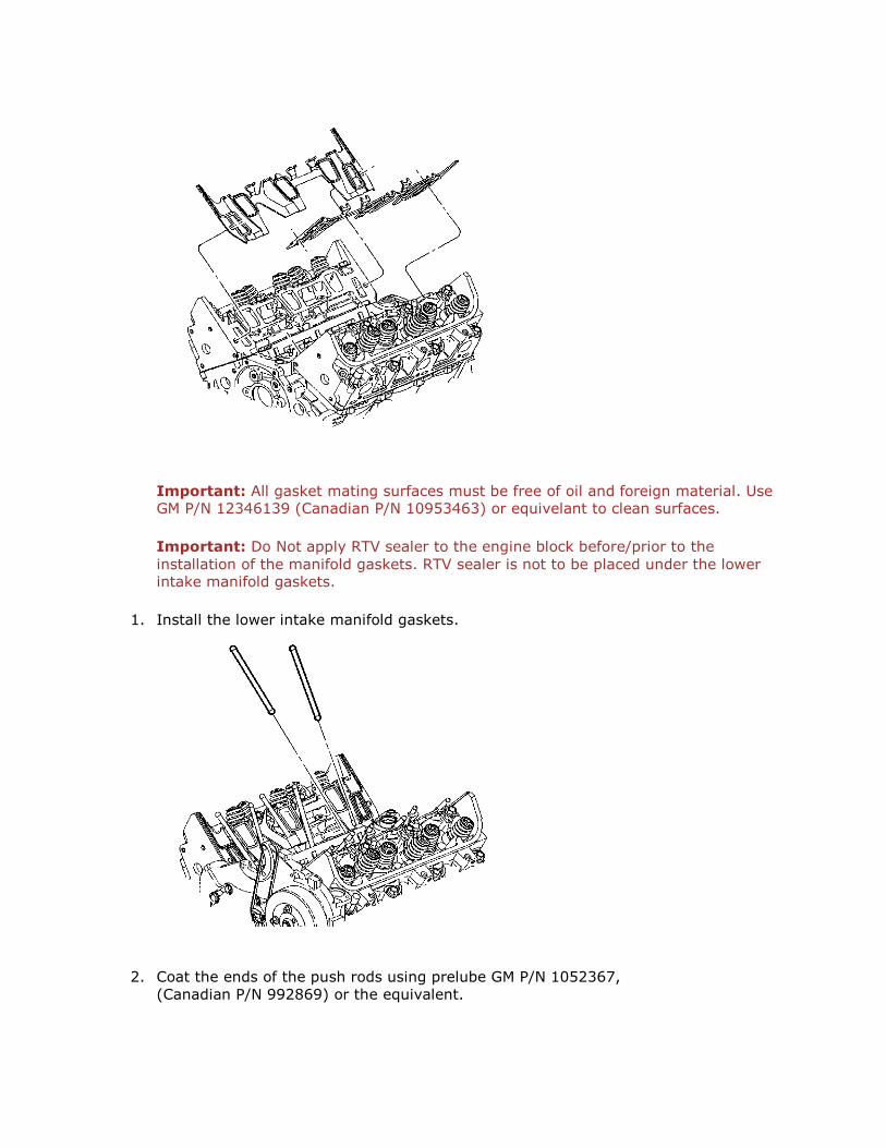
Important: All gasket mating surfaces must be free of oil and foreign material. Use GM P/N 12346139 (Canadian P/N 10953463) or equivelant to clean surfaces.
Important: Do Not apply RTV sealer to the engine block before/prior to the
installation of the manifold gaskets. RTV sealer is not to be placed under the lower intake manifold gaskets.
1. Install the lower intake manifold gaskets.
2. Coat the ends of the push rods using prelube GM P/N 1052367,
(Canadian P/N 992869) or the equivalent.
Important: 1995 and earlier engines use hardened pushrods and steel pushrod
guide plates. For service of 1995 and earlier engines, only intake pushrods with
purple markings and exhaust pushrods with orange markings can be used. Failure to do so may result in engine damage.
Intake pushrods from 1996 and newer engines have either yellow or purple
markings. Exhaust pushrods from 1996 and newer engines have either green or orange markings.
All intake pushrods measure 144.18 mm (5.68 in) long, and all exhaust pushrods
measure 152.51 mm (6.0 in) long.
3. Install the push rods in their original location.
4. Coat the rocker arm friction surfaces using prelube GM P/N 1052367, (Canadian P/N 992869) or the equivalent.
Important: Shims may be required under the valve rocker arm pedestals if
reconditioning has been performed on the cylinder head or its components.
5. Install the valve rocker arms in their original positions.
Notice: Use the correct fastener in the correct location. Replacement fasteners must
be the correct part number for that application. Fasteners requiring replacement or
fasteners requiring the use of thread locking compound or sealant are identified in
the service procedure. Do not use paints, lubricants, or corrosion inhibitors on
fasteners or fastener joint surfaces unless specified. These coatings affect fastener
torque and joint clamping force and may damage the fastener. Use the correct
tightening sequence and specifications when installing fasteners in order to avoid damage to parts and systems.
Important: Thoroughly clean the fastener and tapped hole prior to installation.
6. Install the valve rocker arm bolts.
Tighten Tighten the valve rocker arm bolts to 42 N·m (31 lb ft).
Lower Intake Manifold Installation
Important: All gasket-mating surfaces need to be free of oil, and foreign material.
Use GM P/N 12346139 (Canadian P/N 10953463) or equivalent to clean surfaces.
1. Install the lower intake manifold gaskets.
2. With gaskets in place apply a small drop 8-10 mm (0.31-0.39 in) of RTV sealer
GM P/N 12346141 (Canadian P/N 10953433) or equivalent to the 4 corners of the
intake manifold to block joint (1).
3. Connect the 2 small drops with a bead of RTV sealer that is between 8-10 mm (0.31-
0.39 in) wide and 3.0-5.0 mm (0.12-0.20 in) thick (2).
4. Install the lower intake manifold.
Notice: Maximum gasket performance is achieved when using new fasteners, which
contain a thread-locking patch. If the fasteners are not replaced, a thread locking
chemical must be applied to the fastener threads. Failure to replace the fasteners or apply a thread-locking chemical MAY reduce gasket sealing capability.
Notice: Use the correct fastener in the correct location. Replacement fasteners must
be the correct part number for that application. Fasteners requiring replacement or
fasteners requiring the use of thread locking compound or sealant are identified in
the service procedure. Do not use paints, lubricants, or corrosion inhibitors on
fasteners or fastener joint surfaces unless specified. These coatings affect fastener
torque and joint clamping force and may damage the fastener. Use the correct
tightening sequence and specifications when installing fasteners in order to avoid damage to parts and systems.
Important: All lower intake manifold bolts need to be cleaned, free of any foreign
material, and reused only if new bolts are unavailable. Use GM P/N 12345382
(Canadian P/N 10953489) or equivalent and apply to the old intake manifold bolt
threads.
Important: Manufacturer recommends the center bolts be fully torqued before the diagonal bolts to assure proper seal ability.
Important: Lower intake manifold bolts in location 6 and 7 should be torqued to specification using a crows foot type tool.
5. Install the lower intake manifold bolts.
Tighten
1. Tighten the vertical lower intake manifold bolts (1, 2, 3, 4) in sequence to
7 N·m (62 lb in) on the first pass.
2. Tighten the diagonal lower intake manifold bolts (5, 6, 7, 8) in sequence to
7 N·m (62 lb in) on the first pass.
3. Tighten the vertical lower intake manifold bolts (1, 2, 3, 4) in sequence to
13 N·m (115 lb in) on the final pass.
4. Tighten the diagonal lower intake manifold bolts (5, 6, 7, 8) in sequence to 25 N·m (18 lb ft) on the final pass.
Install the heater inlet pipe.
6. Install the heater inlet pipe nut.
Tighten Tighten the heater inlet pipe nut to 25 N·m (18 lb ft).
Important: Do not use the fuel injector O-ring seals twice. Install NEW fuel injector O-ring seals during assembly.
Important: Do not press on the fuel pressure regulator valve when installing the
fuel injector rail assembly.
7. Install the fuel injector rail assembly.
8.1. Install the fuel injector O-rings using GM P/N 12345616,
(Canadian P/N 993182) or equivalent.
8.2. Install the injector nozzles into the lower intake manifold injector bores.
8.3. Press on the injector rail using the palms of both hands until the injectors are
fully seated.
10. Install the fuel injector rail bolts.
Tighten Tighten the fuel injector rail bolts to 10 N·m (89 lb in).
Important: Do not use the fuel injector O-ring seals twice. Install NEW fuel injector O-ring seals during assembly.
11. Install the fuel feed and return pipe retaining clip.
12. Install the fuel feed and return pipe retaining clip bolt.
Tighten Tighten the fuel feed and return pipe retaining clip bolt to 8 N·m (71 lb in).
Upper Intake Manifold Installation
1. Install the upper intake manifold gaskets. 2. Install the upper intake manifold.
Notice: Use the correct fastener in the correct location. Replacement fasteners must
be the correct part number for that application. Fasteners requiring replacement or
fasteners requiring the use of thread locking compound or sealant are identified in
the service procedure. Do not use paints, lubricants, or corrosion inhibitors on
fasteners or fastener joint surfaces unless specified. These coatings affect fastener
torque and joint clamping force and may damage the fastener. Use the correct
tightening sequence and specifications when installing fasteners in order to avoid damage to parts and systems.
3. Install the upper intake manifold bolts and studs. Apply threadlock GM P/N 12345382
(Canadian P/N 10953489) to the threads.
Tighten Tighten the upper intake manifold bolts and studs to 25 N·m (18 lb ft).
4. Install the EGR valve pipe and bolt to the EGR.
Tighten Tighten the EGR valve pipe bolt to 25 N·m (18 lb ft).
5. Install the EGR valve.
6. Install the EGR valve bolts.
Tighten Tighten the EGR valve bolts to 25 N·m (18 lb ft).
7. Install the map sensor bracket and bolts.
Tighten Tighten the MAP sensor bracket bolts to 25 N·m (18 lb ft).
8. Install the MAP sensor. 9. Install the MAP sensor bolts.
Tighten
Tighten the MAP sensor bolts to 5 N·m (44 lb in).
10. Install the MAP sensor electrical connector.
11. Install the vacuum lines to the upper intake manifold.
12. Install the throttle cable bracket.
13. Install the throttle cable bracket bolts.
Tighten Tighten the throttle cable bracket bolts to 13 N·m (115 lb in).