NATIONAL ANNEX NATIONAL ANNEX TO CYS EN 1993-1-1:2005 (Including A1:2014 and AC:2009) Eurocode 3: Design of steel structures Part 1-1: General rules and rules for buildings NA to CYS EN 1993-1-1:2005 (Including A1:2014 and AC:2009)
Transcript
NATIONAL ANNEX
NATIONAL ANNEXTOCYS EN 1993-1-1:2005 (Including A1:2014 and AC:2009)
Eurocode 3: Design of steel structures
Part 1-1: General rules and rules for buildings
NA to CYS EN 1993-1-1:2005(Including A1:2014 and AC:2009)
NATIONAL ANNEX
TO
CYS EN 1993-1-1:2005+A1:2014+AC:2009 Eurocode 3:
Design of steel structures Part 1-1: General rules and rules for buildings
This National Annex has been approved by the Board of Directors of the Cyprus Organisation for Standardisation (CYS) on 14.06.2019.
Copyright
Right to reproduce and distribute belongs to the Cyprus Organisation for Standardisation.
No part of this publication may be reproduced or utilized in any form or by any means, electronic or mechanical, including photocopying, without permission in writing from Cyprus Organisation for Standardisation.
If you have any questions about standards copyright, please contact Centre of Information and Customer Service at the Cyprus Organisation for Standardisation phone: +357 22 411413/4 email: [email protected]
National Annex to CYS EN 1993-1-1:2005+A1:2014+AC:2009 Eurocode 3: Design of Steel Structures Part 1-1: General rules and rules for buildings
CYS TC 18 Page 2 of 9
INTRODUCTION This National Annex has been prepared by the CYS TC 18 National Standardisation Technical Committee of the Cyprus Organisation for Standardisation. (CYS).
NA 1 SCOPE This National Annex is to be used in conjunction with CYS EN 1993-1-1:2005+Α1:2014+AC: 2009.Any reference in the rest of this text to CYS EN 1993-1-1:2005 means the above document.
This National Annex gives:
(a) Nationally Determined Parameters described in the following clauses of CYS EN 1993-1-1:2005 (see Section NA 2):
(b) Decisions on the use of CYS EN 1993-1-1:2005 informative annexes (see Section NA 3)
(c) References to non-contradictory complementary information to assist the user to applyCYS EN 1993-1-1:2005 (see Section NA 4)
National Annex to CYS EN 1993-1-1:2005+A1:2014+AC:2009 Eurocode 3: Design of Steel Structures Part 1-1: General rules and rules for buildings
CYS TC 18 Page 3 of 9
NA 2 NATIONALLY DETERMINED PARAMETERS
NA 2.1 Clause 2.3.1 (1) Actions and environmental influences Refer to the parts of CYS EN 1991 (including the respective Corrigenda and Amendments) and their National Annexes.
NA 2.2 Clause 3.1 (2) General Refer to CYS EN 1993-1-12:2007/AC:2009 and its National Annex. No information for other steel material and products is provided in this National Annex.
NA 2.3 Clause 3.2.1 (1) Material properties The nominal values of the yield strength fy and the ultimate strength fu for structural steel shall be obtained by adopting the values fy = ReH and fu = Rm direct from the product standard.
NA 2.4 Clause 3.2.2 (1) Ductility requirements The following recommended requirements shall be used:
– fu / fy 1,10;
– elongation at failure not less than 15%;
– u 15y , where y is the yield strain (y = fy / E).
NA 2.5 Clause 3.2.3 (1)P Fracture toughness Refer to CYS EN 1991-1-5:2003/AC:2009 and its National Annex.
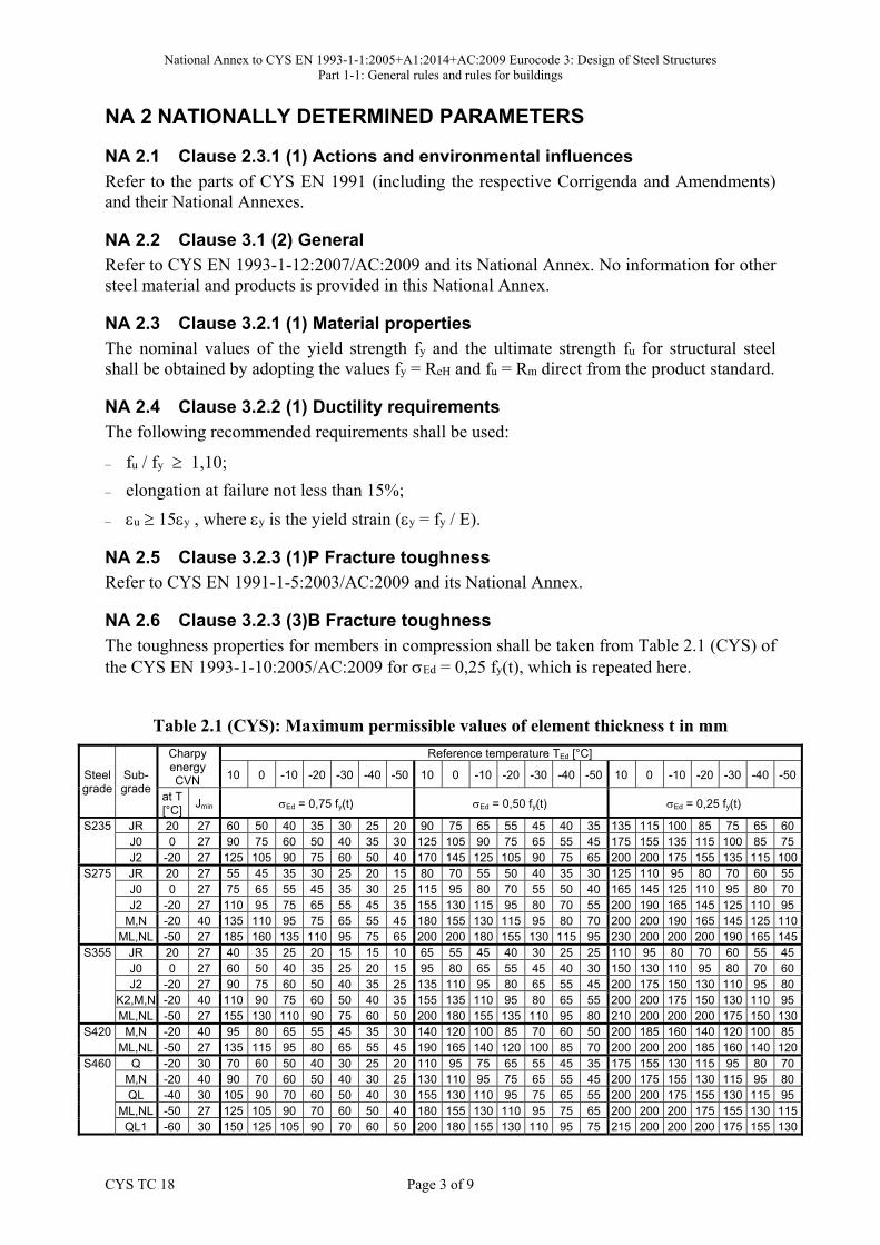
NA 2.6 Clause 3.2.3 (3)B Fracture toughness The toughness properties for members in compression shall be taken from Table 2.1 (CYS) of the CYS EN 1993-1-10:2005/AC:2009 for Ed = 0,25 fy(t), which is repeated here.
Table 2.1 (CYS): Maximum permissible values of element thickness t in mm
NOTE 1 Linear interpolation can be used in applying Table 2.1 (CYS). Most applications require σEd values between σEd = 0,75 fy(t) and σEd = 0,50 fy(t). σEd = 0,25 fy(t) is given for interpolation purposes. Extrapolations beyond the extreme values are not valid.
NOTE 2 For ordering products made of S 690 steels the TJ – values should be specified.
NA 2.7 Clause 3.2.4 (1)B Through-thickness properties The allocation of target values ZEd according to 3.2(2) of CYS EN 1993-1-10:2005/AC:2009 to the quality class in CYS EN 10164 are given in Table 3.2 (CYS).
Table 3.2 (CYS): Choice of quality class according to CYS EN 10164
Target value of ZEd according to CYS EN 1993-1-10:2005/AC:2009
Required value of ZRd according to CYS EN 10164
ZEd ≤ 10 —
10 < ZEd ≤ 20 Z 15
20 < ZEd ≤ 30 Z 25
ZEd > 30 Z 35
NA 2.8 Clause 5.2.1 (3) Effects of deformed geometry of the structure
The lower limit for cr shall be the general limit set in the clause.
NA 2.9 Clause 5.2.2 (8) Structural stability of frames No further information is provided in this National Annex.
NA 2.10 Clause 5.3.2 (3) Imperfections for global analysis of frames The values of initial local bow imperfection, e0 / L, are specified in Table 5.1 (CYS).
Table 5.1 (CYS): Design value of initial local bow imperfection e0 / L for members
Buckling curve according to Table 6.2
elastic analysis
plastic analysis
e0 / L e0 / L a0 1 / 350 1 / 300 a 1 / 300 1 / 250 b 1 / 250 1 / 200 c 1 / 200 1 / 150 d 1 / 150 1 / 100
NA 2.11 Clause 5.3.2 (11) Imperfections for global analysis of frames No further information is provided in this National Annex.
National Annex to CYS EN 1993-1-1:2005+A1:2014+AC:2009 Eurocode 3: Design of Steel Structures Part 1-1: General rules and rules for buildings
CYS TC 18 Page 5 of 9
NA 2.12 Clause 5.3.4 (3) Member imperfections The value of k is 0,5.
NA 2.13 Clause 6.1 (1) General For structures not covered by CYS EN 1993 Part 2 to Part 6 (including the respective Corrigenda and Amendments), the values for the partial factors Mi shall be taken from CYS EN 1993-2:2006/AC:2009.
NA 2.14 Clause 6.1 (1)B General
The values for the partial factors Mi for buildings are:
M0 = 1,00
M1 = 1,00
M2 = 1,25
NA 2.15 Clause 6.3.2.2 (2) Lateral torsional buckling curves – General case
The values of imperfection factor LT are defined in Table 6.3 (CYS).
Table 6.3 (CYS): Imperfection factors for lateral torsional buckling curves
Buckling curve a b c d Imperfection factor LT 0,21 0,34 0,49 0,76
The specification of the symbols for the buckling curves are given in Table 6.4 (CYS).
Table 6.4 (CYS): Lateral torsional buckling curves for cross-sections using equation (6.56)
Cross-section Limits Buckling curve
Rolled I-sections h/b 2 h/b > 2
a b
Welded I-sections h/b 2 h/b > 2
c d
Other cross-sections - d
NA 2.16 Clause 6.3.2.3 (1) Lateral torsional buckling curves for rolled sections or equivalent welded sections
The following recommended limitations shall be used:
4,00,LT (maximum value)
= 0,75 (minimum value)
The specification of the symbols for the lateral torsional buckling curves are given in Table 6.5 (CYS).
National Annex to CYS EN 1993-1-1:2005+A1:2014+AC:2009 Eurocode 3: Design of Steel Structures Part 1-1: General rules and rules for buildings
CYS TC 18 Page 6 of 9
Table 6.5 (CYS): Selection of lateral torsional buckling curve for cross sections using equation (6.57)
Cross-section Limits Buckling curve
Rolled I-sections h/b 2 h/b > 2
b c
Welded I-sections h/b 2 h/b > 2
c d
NA 2.17 Clause 6.3.2.3 (2) Lateral torsional buckling curves for rolled sections or equivalent welded sections
The following recommended minimum values shall be used:
1,0fbut ])8,0(0,21)[k1(5,01f 2LTc
Table 6.6 (CYS) defines the values for the correction factor, kc, of Table 6.6 of CYS EN 1993-1-1:2005.
Table 6.6 (CYS): Correction factors kc
Moment distribution kc
= 1 1,0
-1 1 33,033,1
1
0,94
0,90
0,91
0,86
0,77
0,82
NA 2.18 Clause 6.3.2.4 (1)B Simplified assessment methods for beams with restraints in buildings
The recommended limit value 1,00,LT0c shall be used, see 6.3.2.3 of CYS EN 1993-1-1:2005.
NA 2.19 Clause 6.3.2.4 (2)B Simplified assessment methods for beams with restraints in buildings
The value of fk is 1,10.
National Annex to CYS EN 1993-1-1:2005+A1:2014+AC:2009 Eurocode 3: Design of Steel Structures Part 1-1: General rules and rules for buildings
CYS TC 18 Page 7 of 9
NA 2.20 Clause 6.3.3 (5) Uniform members in bending and axial compression Method 2 is preferred, but Method 1 may be used at the discretion of the designer.
NA 2.21 Clause 6.3.4 (1) General method for lateral and lateral torsional buckling of structural components
The method may be used at the discretion of the designer.
NA 2.22 Clause 7.2.1 (1)B Vertical deflections With reference to Figure A1.1 (CYS) of CYS EN 1990:2002/A1:2005/AC:2010, which is repeated here, the recommended limits for vertical deflections are given in Table NA1.
Figure A1.1 (CYS) - Definitions of vertical deflections Key : wc Precamber in the unloaded structural member w1 Initial part of the deflection under permanent loads of the relevant combination of
actions according to expressions (6.14a) to (6.16b) w2 Long-term part of the deflection under permanent loads w3 Additional part of the deflection due to the variable actions of the relevant
combination of actions according to expressions (6.14a) to (6.16b) wtot Total deflection as sum of w1 , w2 , w3 wmax Remaining total deflection taking into account the precamber
Table NA1: Recommended limits for vertical deflections
Design situation Total deflection limits
Cantilevers Length/180
Beams carrying plaster or other brittle finish Span/360
Other beams (except purlins and sheeting rails) Span/250
Purlins and sheeting rails To suit cladding
NA 2.23 Clause 7.2.2 (1)B Horizontal deflections With reference to Figure A1.2 of CYS EN 1990:2002/A1:2005/AC:2010, which is repeated here, the recommended limits for horizontal deflections are given in Table NA2.
National Annex to CYS EN 1993-1-1:2005+A1:2014+AC:2009 Eurocode 3: Design of Steel Structures Part 1-1: General rules and rules for buildings
CYS TC 18 Page 8 of 9
Figure A1.2 (CYS) - Definition of horizontal displacements Key: u Overall horizontal displacement over the building height Hui Horizontal displacement over a storey height Hi
Table NA2: Recommended limits for horizontal deflections
Design situation Deflection limits
Tops of columns in single storey buildings, except portal frames Height/300
Columns in portal frame buildings, not supporting crane runways To suit cladding
In each storey of a building with more than one storey Storey height/300
On the multistorey building as a whole Building height/500
NA 2.24 Clause 7.2.3 (1)B Dynamic effects The recommended limits for vibration of floors are given in Table NA3.
Table NA3: Recommended limits for vibration of floors
Design situation Lowest natural frequency
Floors over which people walk regularly 5 Hz
Floor which is jumped or danced on in a rhythmical manner 9 Hz
NA 2.25 Clause BB.1.3 (3)B Hollow sections as members No further information is provided in this National Annex.
NA 2.26 Clause C.2.2 (3) Selection The selection of execution class shall be based on either the required consequences class (CC) or the reliability class (RC) or both for any type of structure. The selection of execution class (EXC) should be based on Table C.1 (CYS).
Table C.1 (CYS) – Choice of execution class (EXC)
Reliability Class (RC)
or
Consequences Class (CC)
Type of loading
Static, quasi-static or
seismic DCLa
Fatigueb or
seismic DCM or DCHa
RC3 or CC3 EXC3c EXC3c
National Annex to CYS EN 1993-1-1:2005+A1:2014+AC:2009 Eurocode 3: Design of Steel Structures Part 1-1: General rules and rules for buildings
CYS TC 18 Page 9 of 9
RC2 or CC2 EXC2 EXC3
RC1 or CC1 EXC1 EXC2 a Seismic ductility classes are defined in CYS EN 1998-1Low=DCL; Medium=DCM;
High=DCH. b See CYS EN 1993-1-9 and its National Annex. c EXC4 may be specified for structures with extreme consequences of structural failure.
NA 2.27 Clause C.2.2 (4) Selection Regarding the choice of execution class in terms of types of components or details, as recommended, if EXC1 is selected for a structure, then EXC2 should apply to the following types of component:
a) welded components manufactured from steel products of grade S355 and above;
b) welded components essential for structural integrity that are assembled by welding on theconstruction site;
c) welded components of CHS lattice girders requiring end profile cuts;
d) components with hot forming during manufacturing or receiving thermic treatmentduring manufacturing.
NA 3 DECISION ON THE USE OF INFORMATIVE ANNEXES
NA 3.1 Annex A Annex A may be used.
NA 3.2 Annex B Annex B may be used.
NA 3.3 Annex AB
Annex AB may be used.
NA 3.4 Annex BB
Annex BB may be used.
NA 4 REFERENCES TO NON-CONTRADICTORY COMPLEMENTARY INFORMATION


![9 - ICFA PPT -CYS Presentation[1]Microsoft PowerPoint - 9 - ICFA PPT -CYS Presentation[1].pptx Author Dorene Created Date 1/3/2013 1:27:57 PM ...](https://static.documents.pub/doc/80x56/5ed3e952b38510386857318f/9-icfa-ppt-cys-presentation1-microsoft-powerpoint-9-icfa-ppt-cys-presentation1pptx.jpg)


