Designation: D 3517 – 034 An American National Standard
Standard Specification for“Fiberglass” (Glass-Fiber-Reinforced Thermosetting-Resin)Pressure Pipe1
This standard is issued under the fixed designation D 3517; the number immediately following the designation indicates the year of
original adoption or, in the case of revision, the year of last revision. A number in parentheses indicates the year of last reapproval. A
superscript epsilon (e) indicates an editorial change since the last revision or reapproval.
This standard has been approved for use by agencies of the Department of Defense.
1. Scope*Scope
1.1 This specification covers machine-made fiberglass pipe, 8 in. (200 mm) through 144 in. (3700 mm), intended for use in
water conveyance systems which operate at internal gage pressures of 250 psi (1.72 MPa) or less. Both glass-fiber-reinforced
thermosetting-resin pipe (RTRP) and glass-fiber-reinforced polymer mortar pipe (RPMP) are fiberglass pipes. The standard is
suited primarily for pipes to be installed in buried applications, although it may be used to the extent applicable for other
installations such as, but not limited to, jacking, tunnel lining and sliplining rehabilitation of existing pipelines.
NOTE 1—For the purposes of this standard, polymer does not include natural polymers.
1.2 The values stated in inch-pound units are to be regarded as the standard. The values given in parentheses are provided for
information purposes only.
NOTE 2—There is no similar or equivalent ISO standard.
1.3 The following safety hazards caveat pertains only to the test methods portion, Section 8, of this specification: This standard
does not purport to address all of the safety concerns, if any, associated with its use. It is the responsibility of the user of this
standard to establish appropriate safety and health practices and determine the applicability of regulatory limitations prior to use.
1 This specification is under the jurisdiction of ASTM Committee D20 on Plastics and is the direct responsibility of Subcommittee D20.23 on Reinforced Plastic Piping
Systems and Chemical Equipment.
Current edition approved May 10, 2003. April 1, 2004. Published November 2003. April 2004. Originally approved in 1976. Last previous edition approved 20013 asD 3517 – 013.
1
This document is not an ASTM standard and is intended only to provide the user of an ASTM standard an indication of what changes have been made to the previous version. Becauseit may not be technically possible to adequately depict all changes accurately, ASTM recommends that users consult prior editions as appropriate. In all cases only the current versionof the standard as published by ASTM is to be considered the official document.
*A Summary of Changes section appears at the end of this standard.
D 638 Test Method for Tensile Properties of Plastics
D 695 Test Method for Compressive Properties of Rigid Plastics
D 790 Test Methods for Flexural Properties of Unreinforced and Reinforced Plastics and Electrical Insulating Materials
D 883 Terminology Relating to Plastics
D 1600 Terminology for Abbreviated Terms Relating to PlasticsD 2290 Test Method for Apparent Tensile Strength of Ring or Tubular Plastics and Reinforced Plastics by Split Disk Method
D 2412 Test Method for Determination of External Loading Characteristics of Plastic Pipe by Parallel-Plate Loading
D 2584 Test Method for Ignition Loss of Cured Reinforced Resins
D 2992 Practice for Obtaining Hydrostatic or Pressure Design Basis for “Fiberglass’’ (Glass-Fiber-Reinforced Thermosetting-
Resin) Pipe and Fittings
D 3567 Practice for Determining Dimensions of “Fiberglass” (Glass–Fiber–Reinforced Thermosetting Resin) Pipe and Fittings
D 3892 Practice for Packaging/Packing of Plastics
D 4161 Specification for “Fiberglass” (Glass-Fiber-Reinforced Thermosetting-Resin) Pipe Joints Using Flexible Elastomeric
Seals
F 412 Terminology Relating to Plastic Piping Systems
F 477 Specification for Elastomeric Seals (Gaskets) for Joining Plastic Pipe
2.2 ISO Standard:
ISO 1172 Textile Glass Reinforced Plastics—Determination of Loss on Ignition3
2.3 NSF Standard:
Standard No. 14 for Plastic Piping Components and Related Materials4
3. Terminology
3.1 Definitions:
3.1.1 General—Definitions are in accordance with Terminology D 833 and Terminology F 412 and abbreviations are in
accordance with Terminology D 1600, unless otherwise indicated.
3.2 Definitions of Terms Specific to This Standard:
3.2.1 fiberglass pipe—a tubular product containing glass-fiber reinforcements embedded in or surrounded by cured thermo-
setting resin. The composite structure may contain aggregate, granular, or platelet fillers, thixotropic agents, pigments, or dyes.
Thermoplastic or thermosetting liners or coatings may be included.
3.2.2 flexible joint —a joint that is capable of axial displacement or angular rotation, or both.
3.2.3 liner —a resin layer, with or without filler, or reinforcement, or both, forming the interior surface of the pipe.
3.2.4 qualification test —one or more tests used to prove the design of a product. Not a routine quality control test.
3.2.5 reinforced polymer mortar pipe (RPMP)— a fiberglass pipe with aggregate.
3.2.6 reinforced thermosetting resin pipe (RTRP)— a fiberglass pipe without aggregate.
3.2.7 rigid joint —a joint that is not capable of axial displacement or angular rotation.
3.2.8 surface layer —a resin layer, with or without filler, or reinforcements, or both, applied to the exterior surface of the pipe
structural wall.
4. Classification
4.1 General—This specification covers fiberglass pressure pipe defined by raw materials in the structural wall (type) and liner,
surface layer material (grade), operating pressure (class), and pipe stiffness. Table 1 lists the types, liners, grades, classes, and
stiffnesses that are covered.
NOTE 3—All possible combinations of types, liners, grades, classes, and stiffnesses may not be commercially available. Additional types, liners, grades,
and stiffnesses may be added as they become commercially available. The purchaser should determine for himself or consult with the manufacturer for
the proper class, type, liner, grade and stiffness of pipe to be used under the installation and operating conditions that will exist for the project in which
the pipe is to be used.
4.2 Designation Requirements—The pipe materials designation code shall consist of the standard designation, ASTM D 3517,
followed by type, liner, and grade in Arabic numerals, class by the letter C and two or three Arabic numerals, and pipe stiffness
2 For referenced ASTM standards, visit the ASTM website, www.astm.org, or contact ASTM Customer Service at [email protected]. For Annual Book of ASTM Standards,
Vol 04.02. volume information, refer to the standard’s Document Summary page on the ASTM website.
Annual Book of ASTM Standards, Vol 08.01.3 Available from American National Standards Institute, 11 West 42nd Street, 13th Floor, New York, NY 10036.
Annual Book of ASTM Standards, Vol 08.04.4 Available from the National Sanitation Foundation, P.O. Box 1468, Ann Arbor, MI 48106.
by a capital letter. Table 1 presents a summary of the designation requirements. Thus, a complete material code shall consist of
ASTM D 3517. . . three numerals, C . . . and two or three numerals, and a capital letter.
NOTE 4—Examples of the designation are as follows: (1) ASTM D 3517-1-1-3-C50-A for glass-fiber reinforced aggregate and polyester resin mortar
pipe with a reinforced thermoset liner and an unreinforced polyester resin and sand surface layer, for operation at 50 psi (345 kPa), and having a minimum
pipe stiffness of 9 psi (62 kPa), (2) ASTM D 3517-4-2-6-C200-C for glass-fiber reinforced epoxy resin pipe with a non-reinforced thermoset liner, no
surface layer, for operation at 200 psi (1380 kPa), and having a minimum pipe stiffness of 36 psi (248 kPa).
NOTE 5—Although the “Form and Style for ASTM Standards” manual requires that the type classification be roman numerals, it is recognized that
companies have stencil cutting equipment for this style of type, and it is therefore acceptable to mark the product type in arabic numbers.
5. Materials and Manufacture
5.1 General—The resins, reinforcements, colorants, fillers, and other materials, when combined as a composite structure, shall
produce a pipe that shall meet the performance requirements of this specification.5.2 Wall Composition—The basic structural wall composition shall consist of thermosetting resin, glass fiber reinforcement,
and, if used, an aggregate filler.
5.2.1 Resin—A thermosetting polyester or epoxy resin, with or without filler.
5.2.2 Reinforcement —A commercial grade of E-type glass fibers with a finish compatible with the resin used.
5.2.3 Aggregate—A siliceous sand conforming to the requirements of Specification C 33, except that the requirements for
gradation shall not apply.
NOTE 6—Fiberglass pipe intended for use in the transport of potable water should be evaluated and certified as safe for this purpose by a testing agency
acceptable to the local health authority. The evaluation should be in accordance with requirements for chemical extraction, taste, and odor that are no
less restrictive than those included in National Sanitation Foundation (NSF) Standard 61. The seal or mark of the laboratory making the evaluation should
be included on the fiberglass pipe.
5.3 Liner and Surface Layers—Liner or surface layer, or both, when incorporated into or onto the pipe, shall meet the structural
requirements of this specification.
5.4 Joints—The pipe shall have a joining system that shall provide for fluid tightness for the intended service condition. Aparticular type of joint may be restrained or unrestrained and flexible or rigid depending on the specific configuration and design
conditions.
5.4.1 Unrestrained —Pipe joints capable of withstanding internal pressure but not longitudinal tensile loads.
5.4.1.1 Coupling or Bell-and-Spigot Gasket Joints, with a groove either on the spigot or in the bell to retain an elastomeric
gasket that shall be the sole element of the joint to provide watertightness. For typical joint details see Fig. 1.
5.4.1.2 Mechanical Coupling Joint , with elastomeric seals.
TABLE 1 General Designation Requirements for Fiberglass Pressure Pipe
5.4.1.4 Flanged Joint , both integral and loose ring.
5.4.2 Restrained —Pipe joints capable of withstanding internal pressure and longitudinal tensile loads..
5.4.2.1 Joints similar to those in 5.4.1.1 with supplemental restraining elements.
5.4.2.2 Butt Joint , with laminated overlay.
5.4.2.3 Bell-and-Spigot , with laminated overlay.
5.4.2.4 Bell-and-Spigot , adhesive-bonded joint: Three types of adhesive-bonded joints are permitted by this standard as follows:5.4.2.4.1 Tapered bell-and-spigot , an adhesive joint that is manufactured with a tapered socket for use in conjunction with a
tapered spigot and a suitable adhesive.
5.4.2.4.2 Straight bell-and-spigot , an adhesive joint that is manufactured with an untapered socket for use in conjunction with
an untapered spigot and a suitable adhesive.
5.4.2.4.3 Tapered bell and straight spigot , an adhesive joint that is manufactured with a tapered socket for use with an untapered
spigot and a suitable adhesive.
5.4.2.5 Flanged Joint , both integral and loose ring
5.4.2.6 Mechanical Coupling, an elastomeric sealed coupling with a supplemental restraining elements.
5.4.2.7 Threaded Joints.
NOTE 7—Other types of joints may be added as they become commercially available.
NOTE 8—Restrained joints typically increase service loads on the pipe to greater than those experienced with unrestrained joints. The purchaser is
cautioned to take into consideration all conditions that may be encountered in the anticipated service and to consult the manufacturer regarding the
suitability of a particular type and class of pipe for service with restrained joint systems.
5.5 Gaskets—Elastomeric gaskets when used with this pipe shall conform to the requirements of Specification F 477.
6. Requirements
6.1 Workmanship:
6.1.1 Each pipe shall be free from all defects including indentations, delaminations, bubbles, pinholes, cracks, pits, blisters,
foreign inclusions, and resin-starved areas that due to their nature, degree, or extent, detrimentally affect the strength and
serviceability of the pipe. The pipe shall be as uniform as commercially practicable in color, opacity, density, and other physical
properties.
6.1.2 The inside surface of each pipe shall be free of bulges, dents, ridges, and other defects that result in a variation of inside
diameter of more than 1 ⁄ 8 in. (3.2 mm) from that obtained on adjacent unaffected portions of the surface. No glass fiber
reinforcement shall penetrate the interior surface of the pipe wall.
6.1.3 Joint sealing surfaces shall be free of dents, gouges, and other surface irregularities that will affect the integrity of the
joints.6.2 Dimensions:
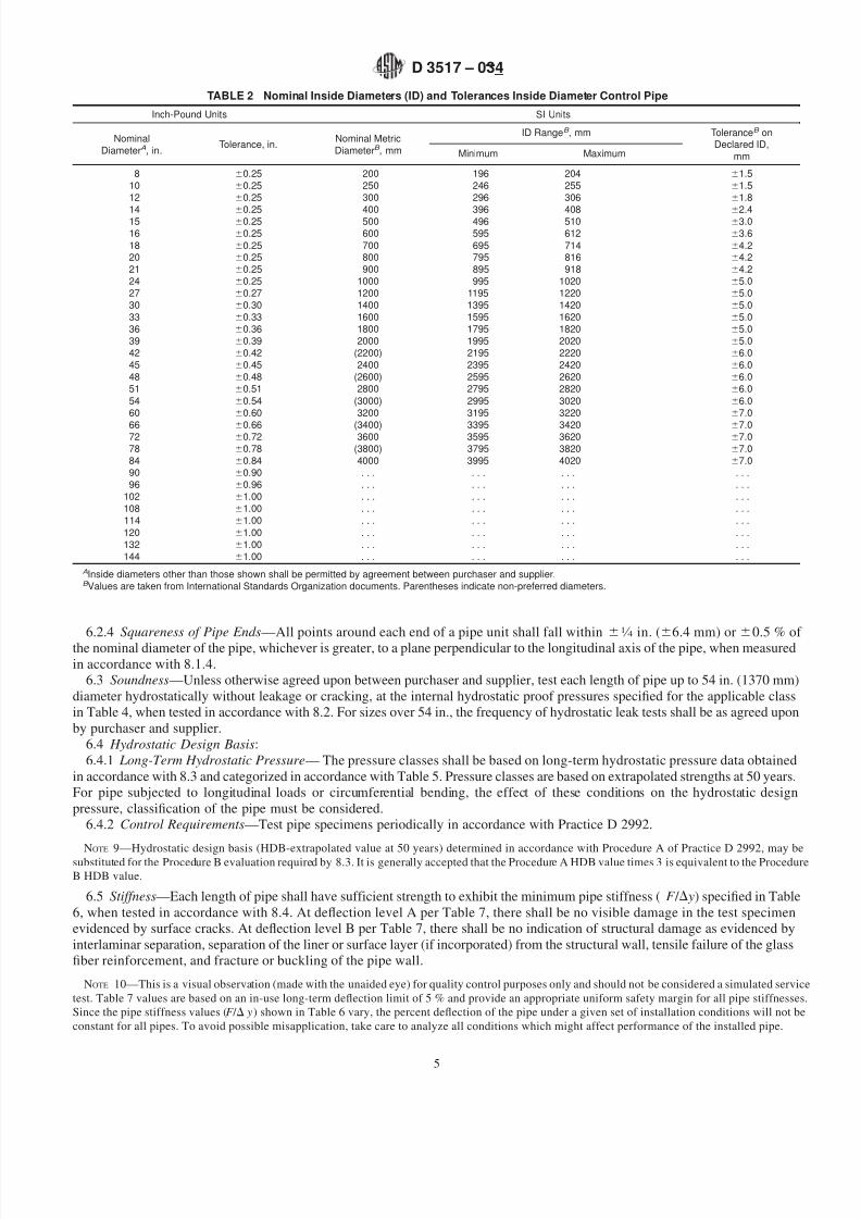
6.2.1 Pipe Diameters—Pipe shall be supplied in the nominal diameters shown in Table 2 or Table 3. The pipe diameter
tolerances shall be as shown in Table 2 or Table 3, when measured in accordance with 8.1.1.
6.2.2 Lengths—Pipe shall be supplied in nominal lengths of 10, 20, 30, 40, and 60 ft. (3.05, 6.10, 9.15, 12.19, and 18.29 m).
The actual laying length shall be the nominal length 62 in. (651 mm), when measured in accordance with 8.1.2. At least 90 %
of the total footage of any one size and class, excluding special order lengths, shall be furnished in the nominal lengths specified
by the purchaser. Random lengths, if furnished, shall not vary from the nominal lengths by more than 5 ft (1.53 m) or 25 %,
whichever is less.
6.2.3 Wall Thickness—The average wall thickness of the pipe shall not be less than the nominal wall thickness published in the
manufacturer’s literature current at the time of purchase, and the minimum wall thickness at any point shall not be less than 87.5 %
of the nominal wall thickness when measured in accordance with 8.1.3.
6.2.4 Squareness of Pipe Ends—All points around each end of a pipe unit shall fall within 61 ⁄ 4 in. (66.4 mm) or 60.5 % of
the nominal diameter of the pipe, whichever is greater, to a plane perpendicular to the longitudinal axis of the pipe, when measured
in accordance with 8.1.4.
6.3 Soundness—Unless otherwise agreed upon between purchaser and supplier, test each length of pipe up to 54 in. (1370 mm)
diameter hydrostatically without leakage or cracking, at the internal hydrostatic proof pressures specified for the applicable class
in Table 4, when tested in accordance with 8.2. For sizes over 54 in., the frequency of hydrostatic leak tests shall be as agreed upon
by purchaser and supplier.
6.4 Hydrostatic Design Basis:
6.4.1 Long-Term Hydrostatic Pressure— The pressure classes shall be based on long-term hydrostatic pressure data obtained
in accordance with 8.3 and categorized in accordance with Table 5. Pressure classes are based on extrapolated strengths at 50 years.
For pipe subjected to longitudinal loads or circumferential bending, the effect of these conditions on the hydrostatic design
pressure, classification of the pipe must be considered.
6.4.2 Control Requirements—Test pipe specimens periodically in accordance with Practice D 2992.
NOTE 9—Hydrostatic design basis (HDB-extrapolated value at 50 years) determined in accordance with Procedure A of Practice D 2992, may be
substituted for the Procedure B evaluation required by 8.3. It is generally accepted that the Procedure A HDB value times 3 is equivalent to the Procedure
B HDB value.
6.5 Stiffness—Each length of pipe shall have sufficient strength to exhibit the minimum pipe stiffness ( F / D y) specified in Table
6, when tested in accordance with 8.4. At deflection level A per Table 7, there shall be no visible damage in the test specimen
evidenced by surface cracks. At deflection level B per Table 7, there shall be no indication of structural damage as evidenced by
interlaminar separation, separation of the liner or surface layer (if incorporated) from the structural wall, tensile failure of the glass
fiber reinforcement, and fracture or buckling of the pipe wall.
NOTE 10—This is a visual observation (made with the unaided eye) for quality control purposes only and should not be considered a simulated service
test. Table 7 values are based on an in-use long-term deflection limit of 5 % and provide an appropriate uniform safety margin for all pipe stiffnesses.
Since the pipe stiffness values (F / D y) shown in Table 6 vary, the percent deflection of the pipe under a given set of installation conditions will not be
constant for all pipes. To avoid possible misapplication, take care to analyze all conditions which might affect performance of the installed pipe.
TABLE 2 Nominal Inside Diameters (ID) and Tolerances Inside Diameter Control Pipe
AInside diameters other than those shown shall be permitted by agreement between purchaser and supplier.B Values are taken from International Standards Organization documents. Parentheses indicate non-preferred diameters.
bell-and-spigot joints with laminated overlay, flanged, bell-and-spigot adhesive bonded and threaded.
6.8 Longitudinal Strength:
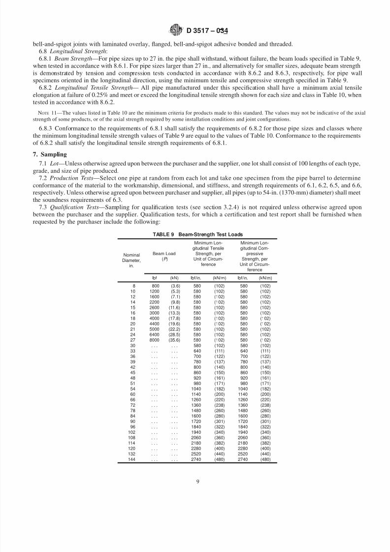
6.8.1 Beam Strength—For pipe sizes up to 27 in. the pipe shall withstand, without failure, the beam loads specified in Table 9,
when tested in accordance with 8.6.1. For pipe sizes larger than 27 in., and alternatively for smaller sizes, adequate beam strength
is demonstrated by tension and compression tests conducted in accordance with 8.6.2 and 8.6.3, respectively, for pipe wall
specimens oriented in the longitudinal direction, using the minimum tensile and compressive strength specified in Table 9.
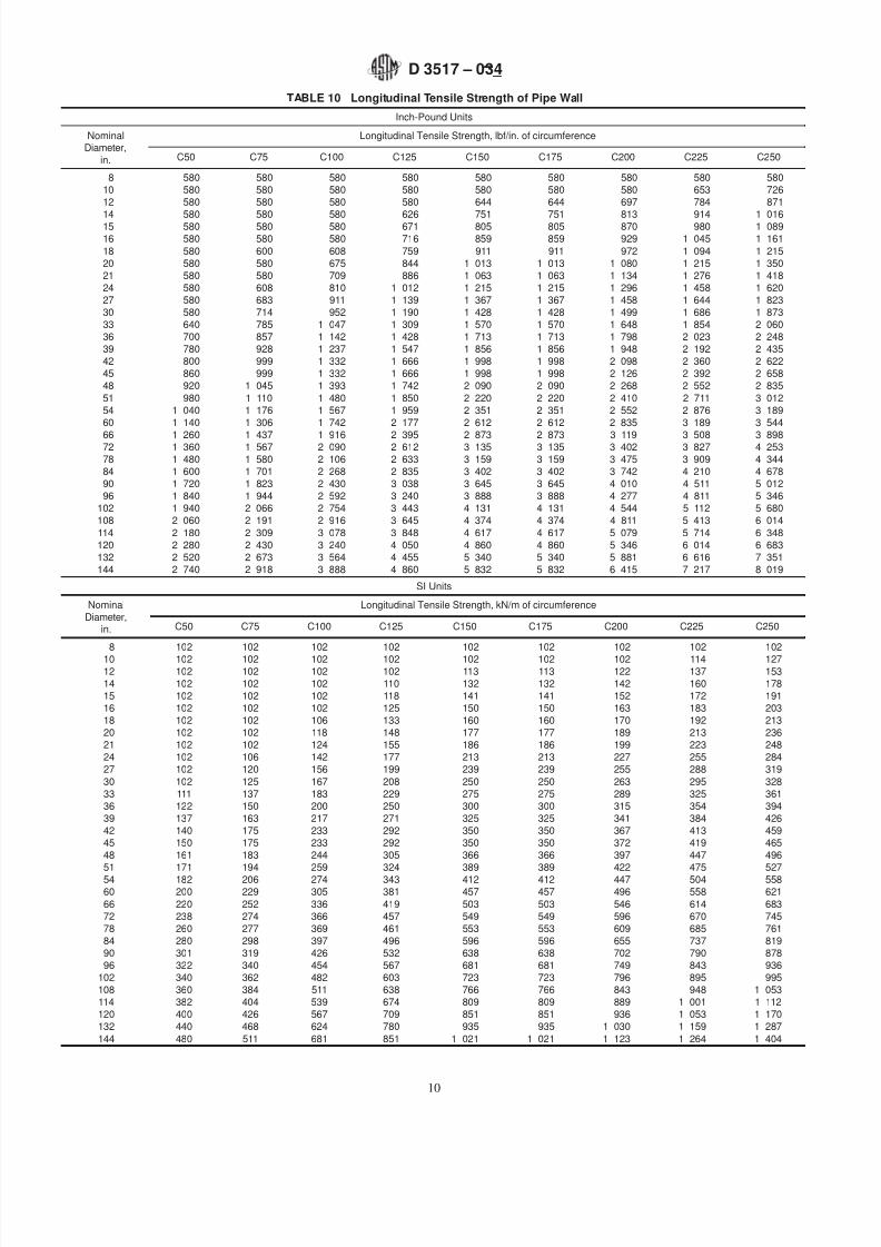
6.8.2 Longitudinal Tensile Strength— All pipe manufactured under this specification shall have a minimum axial tensile
elongation at failure of 0.25% and meet or exceed the longitudinal tensile strength shown for each size and class in Table 10, whentested in accordance with 8.6.2.
NOTE 11—The values listed in Table 10 are the minimum criteria for products made to this standard. The values may not be indicative of the axial
strength of some products, or of the axial strength required by some installation conditions and joint configurations.
6.8.3 Conformance to the requirements of 6.8.1 shall satisfy the requirements of 6.8.2 for those pipe sizes and classes where
the minimum longitudinal tensile strength values of Table 9 are equal to the values of Table 10. Conformance to the requirements
of 6.8.2 shall satisfy the longitudinal tensile strength requirements of 6.8.1.
7. Sampling
7.1 Lot —Unless otherwise agreed upon between the purchaser and the supplier, one lot shall consist of 100 lengths of each type,
grade, and size of pipe produced.
7.2 Production Tests—Select one pipe at random from each lot and take one specimen from the pipe barrel to determine
conformance of the material to the workmanship, dimensional, and stiffness, and strength requirements of 6.1, 6.2, 6.5, and 6.6,
respectively. Unless otherwise agreed upon between purchaser and supplier, all pipes (up to 54-in. (1370-mm) diameter) shall meetthe soundness requirements of 6.3.
7.3 Qualification Tests—Sampling for qualification tests (see section 3.2.4) is not required unless otherwise agreed upon
between the purchaser and the supplier. Qualification tests, for which a certification and test report shall be furnished when
7.4 Control Tests—The following test is considered a control requirement and shall be performed as agreed upon between the
purchaser and the supplier:
7.4.1 Soundness Test —60-in. (1520-mm) diameter pipe and larger.7.4.2 Perform the sampling and testing for the control requirements for hydrostatic design basis at least once every two years.
7.5 For individual orders conduct only those additional tests and numbers of tests specifically agreed upon between the
purchaser and the supplier.
8. Test Methods
8.1 Dimensions:
8.1.1 Diameters:
8.1.1.1 Inside Diameter —Take inside diameter measurements at a point approximately 6 in. (152 mm) from the end of the pipe
section using a steel tape or an inside micrometer with graduations of 1 ⁄ 16 in. (1 mm) or less. Make two 90° opposing measurements
at each point of measurement and average the readings.
8.1.1.2 Outside Diameter —Determine in accordance with Test Method D 3567.
8.1.2 Length—Measure with a steel tape or gage having graduations of 1 ⁄ 16 in. (1 mm) or less. Lay the tape or gage on or inside
the pipe and measure the overall laying length of the pipe.
8.1.3 Wall Thickness—Determine in accordance with Test Method D 3567.8.1.4 Squareness of Pipe Ends—Rotate the pipe on a mandrel or trunnions and measure the runout of the ends with a dial
indicator. The total indicated reading is equal to twice the distance from a plane perpendicular to the longitudinal axis of the pipe.
Alternatively, when squareness of pipe ends is rigidly fixed by tooling, the tooling may be verified and reinspected at frequent
enough intervals to ensure that the squareness of the pipe ends is maintained within tolerance.
8.2 Soundness—Determine soundness by a hydrostatic proof test procedure. Place the pipe in a hydrostatic pressure testing
machine that seals the ends and exerts no end loads. Fill the pipe with water, expelling all air, and apply internal water pressure
at a uniform rate not to exceed 50 psi (345 kPa)/s until the Table 4 test pressure specified in accordance with 6.3 is reached.
Maintain this pressure for a minimum of 30 s. The pipe shall show no visual signs of weeping, leakage, or fracture of the structural
wall.
8.3 Long-Term Hydrostatic Pressure— Determine the long-term hydrostatic pressure at 50 years in accordance with Procedure
B of Practice D 2992, with the following exceptions permitted:
8.3.1 Test at ambient temperatures between 50 and 110°F (10 and 43.5°C) and report the temperature range experienced during
the tests.NOTE 12—Tests indicate no significant effects on long-term hydrostatic pressure within the ambient temperature range specified.
8.3.2 Determine the hydrostatic design basis for the glass fiber reinforcement in accordance with the method in Annex A1.
8.3.3 Calculate the long-term hydrostatic pressure and categorize by class in accordance with Table 5. A1.6 explains how to
calculate the long-term hydrostatic pressure.
8.4 Stiffness—Determine the pipe stiffness (F / D y) at 5 % deflection for the specimen, using the apparatus and procedure of Test
Method D 2412, with the following exceptions permitted:
8.4.1 Measure the wall thickness to the nearest 0.01 in. (0.25 mm).
8.4.2 Load the specimen to 5 % deflection and record the load. Then load the specimen to deflection level A per Table 7 and
examine the specimen for visible damage evidenced by surface cracks. Then load the specimen to deflection level B per Table 7
and examine for evidence of structural damage, as evidenced by interlaminar separation, separation of the liner or surface layer
(if incorporated) from the structural wall, tensile failure of the glass fiber reinforcement, and fracture or buckling of the pipe wall.
Calculate the pipe stiffness at 5 % deflection.
8.4.3 For production testing, test only one specimen to determine the pipe stiffness.8.4.4 The maximum specimen length shall be 12 in. (305 mm), or the length necessary to include stiffening ribs, if they are used,
whichever is greater.
NOTE 13—As an alternative to determining the pipe stiffness using the apparatus and procedure of Test Method D 2412 the supplier may submit to
the purchaser for approval a test method and test evaluation on Test Method D 790, accounting for the substitution of curved test specimens and
measurement of stiffness at 5 % deflection.
8.5 Hoop-Tensile Strength—Determine the hoop-tensile strength by Test Method D 2290, except that the sections on Apparatus
and Test Specimens may be modified to suit the size of specimens to be tested, and the maximum load rate may not exceed 0.10
in/min. Alternatively, Test Method D 638 may be employed. Specimen width may be increased for pipe wall thicknesses greater
than 0.55 in. (14 mm). Means may be provided to minimize the bending moment imposed during the test. Cut three specimens
from the test sample. Record the load to fail each specimen and determine the specimen width as close to the break as possible.
Use the measured width and failure load to calculate the hoop-tensile strength.
8.5.1 Alternative Minimum Hoop-Tensile Strength Requirement —As an alternative, the minimum hoop-tensile strength values
may be determined as follows:
F 5 ~S i / S r !~Pr ! (2)
where:F = required minimum hoop tensile strength, lbf/in.,S i
= initial design hoop tensile stress, psi,S r
= hoop tensile stress at rated operating pressure, psi,P = rated operating pressure class, psi, andr = inside radius of pipe, in.
NOTE 14—A value of F less than 4 Pr results in a lower factor of safety on short term loading than required by the values in Table 8.
The value for S i should be established by considering the variations in glass reinforcement strength and manufacturing methods,
but in any case should not be less than the 95 % lower confidence value on stress at 0.1 h, as determined by the manufacturer’s
testing carried out in accordance with 6.4. The value for S r should be established from the manufacturer’s hydrostatic design basis.
8.6 Longitudinal Strength:
8.6.1 Beam Strength—Place a 20-ft (6.1-m) nominal length of pipe on saddles at each end. Hold the ends of the pipe round
during the test. Apply beam load for the diameter of pipe shown in Table 9 simultaneously to the pipe through two saddles located
at the third points of the pipe (see Fig. 2). The loads shall be maintained for not less than 10 min with no evidence of failure. The
testing apparatus shall be designed to minimize stress concentrations at the loading points.8.6.2 Longitudinal Tensile Strength— Determine in accordance with Test Method D 638, except the provision for maximum
thickness shall not apply.
8.6.3 Longitudinal Compressive Strength— Determine in accordance with Test Method D 695.
9. Packaging and Package Marking
9.1 Mark each length of pipe that meets or is part of a lot that meets the requirements of this specification at least once in letters
not less than 1 ⁄ 2 in. (12 mm) in height and of bold-type style in a color and type that remains legible under normal handling and
installation procedures. The marking shall include the nominal pipe size, manufacturer’s name or trademark, this ASTM
specification number: D 3517, type, liner, grade, class, and stiffness in accordance with the designation code in 4.2.
9.2 Prepare pipe for commercial shipment in such a way as to ensure acceptance by common or other carriers.
9.3 All packing, packaging, and marking provisions of Practice D 3892 shall apply to this specification.
ANNEX
(Mandatory Information)
A1. ALTERNATIVE HYDROSTATIC DESIGN METHOD
A1.1 The following symbols are used:
S = tensile stress in the glass fiber reinforcement in the hoop orientation corrected for the helix angle,
= actual cross-sectional area of glass-fiber reinforcement applied around the circumference of the pipe, in.2 /in.,u = plane angle between hoop-oriented reinforcement and longitudinal axis of the pipe (helix angle),
andHDB = hydrostatic-design basis, psi.
A1.2 The hydrostatic design is based on the estimated tensile stress of the reinforcement in the wall of the pipe in the
circumferential (hoop) orientation that will cause failure after 50 years of continuously applied pressure as described in Procedure
B of Practice D 2992. Strength requirements are calculated using the strength of hoop-oriented glass reinforcement only, corrected
for the helix angle of the fibers.
A1.3 Hoop-Stress Calculation is derived from the ISO equation for hoop stress, as follows:
This stress is used as the ordinate (long-term strength) in calculating the regression line and lower confidence limit in accordance
with Annexes A1 and A3 of Practice D 2992.
NOTE A1.1—The calculated result for S may be multiplied by the factor 6.895 to convert from psi to kPa.
A1.4 Hydrostatic-Design Basis—The value of S is determined by extrapolation of the regression line to or 50 years in
accordance with Practice D 2992.
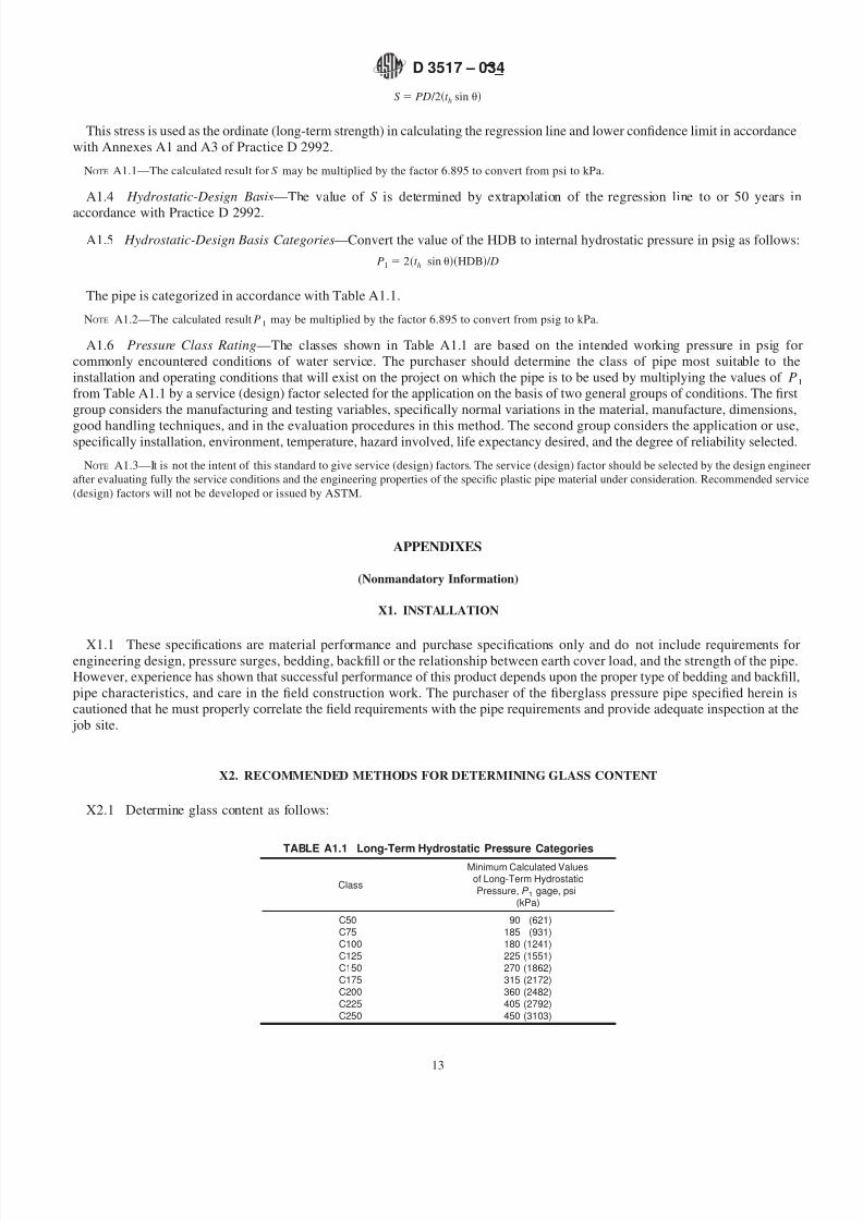
A1.5 Hydrostatic-Design Basis Categories—Convert the value of the HDB to internal hydrostatic pressure in psig as follows:
P1 5 2~t h sin u!~HDB! / D
The pipe is categorized in accordance with Table A1.1.
NOTE A1.2—The calculated result P1
may be multiplied by the factor 6.895 to convert from psig to kPa.
A1.6 Pressure Class Rating—The classes shown in Table A1.1 are based on the intended working pressure in psig for
commonly encountered conditions of water service. The purchaser should determine the class of pipe most suitable to the
installation and operating conditions that will exist on the project on which the pipe is to be used by multiplying the values of P1
from Table A1.1 by a service (design) factor selected for the application on the basis of two general groups of conditions. The first
group considers the manufacturing and testing variables, specifically normal variations in the material, manufacture, dimensions,
good handling techniques, and in the evaluation procedures in this method. The second group considers the application or use,specifically installation, environment, temperature, hazard involved, life expectancy desired, and the degree of reliability selected.
NOTE A1.3—It is not the intent of this standard to give service (design) factors. The service (design) factor should be selected by the design engineer
after evaluating fully the service conditions and the engineering properties of the specific plastic pipe material under consideration. Recommended service
(design) factors will not be developed or issued by ASTM.
APPENDIXES
(Nonmandatory Information)
X1. INSTALLATION
X1.1 These specifications are material performance and purchase specifications only and do not include requirements forengineering design, pressure surges, bedding, backfill or the relationship between earth cover load, and the strength of the pipe.
However, experience has shown that successful performance of this product depends upon the proper type of bedding and backfill,
pipe characteristics, and care in the field construction work. The purchaser of the fiberglass pressure pipe specified herein is
cautioned that he must properly correlate the field requirements with the pipe requirements and provide adequate inspection at the
job site.
X2. RECOMMENDED METHODS FOR DETERMINING GLASS CONTENT
X2.1.1 By ignition loss analysis in accordance with Test Method D 2584 or ISO 1172.
X2.1.2 As a process control, by weight of the glass fiber reinforcement applied by machine into the pipe structure.
SUMMARY OF CHANGES
Committee D20 has identified the location of selected changes to this standard since the last issue, D 3517–01,
that may impact this standard.
(1) Added definitions for rigid and flexible joint.
(2) Updated joint definitions and categories to be consistent with current industry availability and practice. Also added a cautionary
note regarding increased pipe loads when using restrained joints.
(3) Redefined joint performance requirements to be consistent with the revised definitions.
(4) Added a requirement for a minimum axial strain at failure.
(5) Updated Table 3 for metric diameter series to be consistent with ISO and CEN standards.
(6 ) Added additional installations to the scope.
ASTM International takes no position respecting the validity of any patent rights asserted in connection with any item mentioned
in this standard. Users of this standard are expressly advised that determination of the validity of any such patent rights, and the risk
of infringement of such rights, are entirely their own responsibility.
This standard is subject to revision at any time by the responsible technical committee and must be reviewed every five years and
if not revised, either reapproved or withdrawn. Your comments are invited either for revision of this standard or for additional standards and should be addressed to ASTM International Headquarters. Your comments will receive careful consideration at a meeting of the
responsible technical committee, which you may attend. If you feel that your comments have not received a fair hearing you should make your views known to the ASTM Committee on Standards, at the address shown below.
This standard is copyrighted by ASTM International, 100 Barr Harbor Drive, PO Box C700, West Conshohocken, PA 19428-2959,
United States. Individual reprints (single or multiple copies) of this standard may be obtained by contacting ASTM at the above address or at 610-832-9585 (phone), 610-832-9555 (fax), or [email protected] (e-mail); or through the ASTM website