Damage and fatigue Continuum damage mechanics modeling for fatigue of materials and structures Rodrigue Desmorat LMT-Cachan ENS Cachan/Université Paris 6/CNRS 61 avenue du président Wilson F-94235 Cachan Cedex, France [email protected]ABSTRACT. Application of damage mechanics to fatigue is addressed in the present paper. The ability of Lemaitre’s damage law to describe low and high cycle fatigue failure of metals is illus- trated. Its generalization into an evolution law modeling a damage rate governed by the main dissipative mechanics applies to concrete, elastomers, rocks and to probably other materials. The importance of rate written laws is emphasized. RÉSUMÉ. On décrit dans le présent article comment la mécanique de l’endommagement permet de modéliser la fatigue des matériaux. La loi de Lemaitre permet de rendre compte de la fatigue à faibles et à grands nombres de cycles des métaux. Sa généralisation en une loi d’évolution gouvernée par le mécanisme dissipatif principal permet de l’appliquer aux bétons, élastomères, roches et à probablement d’autres matériaux. L’importance d’une écriture en vitesse est souli- gnée. KEYWORDS: damage, fatigue, metals, concrete, elastomers, rocks. MOTS-CLÉS : endommagement, fatigue, métaux, béton, élastomères, roche REGC – 10/2006. Geomechanics in energy production, pages 849 to 877
Transcript
Damage and fatigue
Continuum damage mechanics modelingfor fatigue of materials and structures
Rodrigue Desmorat
LMT-CachanENS Cachan/Université Paris 6/CNRS61 avenue du président WilsonF-94235 Cachan Cedex, [email protected]
ABSTRACT. Application of damage mechanics to fatigue is addressed in the present paper. Theability of Lemaitre’s damage law to describe low and high cycle fatigue failure of metals is illus-trated. Its generalization into an evolution law modeling a damage rate governed by the maindissipative mechanics applies to concrete, elastomers, rocks and to probably other materials.The importance of rate written laws is emphasized.
RÉSUMÉ. On décrit dans le présent article comment la mécanique de l’endommagement permetde modéliser la fatigue des matériaux. La loi de Lemaitre permet de rendre compte de la fatigueà faibles et à grands nombres de cycles des métaux. Sa généralisation en une loi d’évolutiongouvernée par le mécanisme dissipatif principal permet de l’appliquer aux bétons, élastomères,roches et à probablement d’autres matériaux. L’importance d’une écriture en vitesse est souli-gnée.
REGC – 10/2006. Geomechanics in energy production, pages 849 to 877
850 REGC – 10/2006. Geomechanics in energy production
1. Introduction
Continuum damage mechanics (CDM) is a powerful tool to modelthe degrada-tion of materials, the stress softening encountered (and represented) leading to strainlocalization and rupture. Many damage models exist for concrete (Mazars, 1984, Or-tiz, 1985, Resende, 1987, Laborderieet al., 1990, Mazarset al., 1990, Olleret al.,1990, Yazdaniet al., 1990, Papaet al., 1996, Meschkeet al., 1998, Murakamietal., 1997, Halmet al., 1998, Fichantet al., 1999, Geerset al., 2000, Ragueneauet al.,2000, Gatuingtet al., 2003), metals (Gurson, 1977, Lemaitreet al., 1978, Tvergaardetal., 1984, Lemaitreet al., 1985, Chabocheet al., 1988, Lemaitreet al., 2000), maybeless for elastomers (Simo, 1987, Godvindjeeet al., 1991, Mieheet al., 2000, Can-tournetet al., 2003) or rocks (Marigo, 1981, Homand-Etienneet al., 1998, Charlez,1991, Chiarilliet al., 2003, Conilet al., 2004, Salariet al., 2004), and today’s mainresearch efforts concern the numerical difficulties associated with these models:
– avoiding the mesh dependency by regularization methods: nonlocal models(Pijaudier-Cabotet al., 1987, Aifantis, 1987, Peerlings, 1997, Jiraseket al., 2001, Ji-rasek, 2004), visco- or delay-damage (Dubé, 1994, Ladevèze, 1995), phenomenon ofobscuration of process zones (Denoualet al., 2002)...
– ensuring the transition from continuous damage to discrete cracking: determi-nation of the size and orientation of the mesocrack initiated (Mazarset al., 1996,Lemaitreet al., 2005), discontinuity modeling, XFEM (Melenket al., 1996, Moësetal., 1999, Jirasek, 2002a, Jirasek, 2002b),
– allowing the computational coupling with multi-scale andmulti-timescalephysics, such as for thermo-chemo-hydro-mechanics problems,
– making the computations robust and fast, such as by use of extensive parallelism.
Point probably less known, damage mechanics is also powerful for fatigue, evenif this topic is usually addressed with specific engineeringrules modeling directly theWöhler (or Manson-Coffin) curves of materials (Mansonet al., 1964, Aas-Jackobsenet al., 1973, Tepferset al., 1979, Ramakrishnanet al., 1992). A fatigue law for con-crete can be a straight line in the periodic maximum applied stressσMax vs the loga-rithm of the number of cycles to rupturelogNR diagram, generally parametrized bythe stress ratioRσ = σmin/σMax (with σmin the minimum applied stress). Such areference curve is 1D so how to apply it to 3D states of varyingamplitude stresses?What is then a stress amplitude? How to define a stress ratio? Many difficulties arisetoday due to the will of making Finite Element computations for which the state ofstress is far to remain uniaxial and the loading type is far toremain stress controlled,even proportional and/or cyclic.
The present paper focus on the adavantages of considering CDM framework forfatigue, more precisely of considering Lemaitre’s damage law and extending it to nonmetallic materials as concrete, elastomers, rocks...
Damage and fatigue 851
2. Amplitude damage laws
A first, natural, kind of damage model for fatigue is simply written by relating thedamage, denotedD, to the number of cyclesN . Setting for an experimenti leadingto a number of cycles to ruptureNRi for a stress amplitude∆σi,
D =N
NRi[1]
allows to recover Miner’s linear accumulation rule for multi-level loadings made ofblocks, each made ofni cycles of constant amplitude,
∑
i
Di = 1 −→∑
i
ni
NRi= 1 [2]
This formulation also defines the damage increment per cycleδDδN as1/NR, damage
increment which can more generally be set as a function of thecurrent damageD,of the stress amplitude and of the stress ratioRσ (Lemaitreet al., 1984, Huaet al.,1984, Chabocheet al.,1988),
δD
δN= g(D) Gσ(∆σ,Rσ) [3]
TheRσ dependency models the effect of different mean stresses on Wöhler curves.
People initially thought that introducing aD dependency as in Equation [3] com-bined with the definition of a critical damageDc < 1 (such asNR = N(Dc)) wouldrecover a nonlinear (observed) damage accumulation (
∑ ni
NRi6= 1). This is not the
case as one has for a constant amplitude loading:
δD
g(D)= Gσ(∆σ,Rσ) δN [4]
which gives by integration,
∫ Dc
0
dD
g(D)= Gσ(∆σ,Rσ) NR [5]
so that the Wöhler curve is gained as:
NR =1
Gσ(∆σ,Rσ)
∫ Dc
0
1
g(D)dD [6]
For a blocki (made ofni cycles) of a multi-level loading, each of amplitude∆σi andof stress ratioRi
σ, one has similarly
∫ Di
Di−1
dD
g(D)= Gσ(∆σi, Ri
σ) ni =ni
NRi
∫ Dc
0
dD
g(D)[7]
852 REGC – 10/2006. Geomechanics in energy production
where the damage at the end (resp. at the begining) of the block i isDi (resp.Di−1)andNRi is gained from Equation [6]. The sum
∑
i
∫Di
Di−1
dDg(D) equals
∫ Dc
0dD
g(D) andEquation [7] unfortunately leads to linear Miner rule
∑ ni
NRi= 1.
To obtain a non linear damage accumulation, a more complex modeling is nec-essary, showing a first limitations (in 1D!) of stress amplitude laws. Other limi-tations concern the extension of Equation [3] to strain controlled tests and to noncyclic loadings encountered in random fatigue or in seismicapplications. Note thatthe link between a stress and a strain formulation is not clear for nonlinear materials atleast as long as no rate written damage model is defined (Lemaitre et al.,1985, Paas,1990, Lemaitre, 1992, Paaset al.,1993, Peerlings, 1997, Bodinet al.,2002, Lemaitreet al.,2005).
3. Damage evolution laws for fatigue
From a thermodynamics point of view, laws function of the current number ofcyclesN are not constitutive equations. They incorporate information on the load-ing and must be theoretically recovered from real constitutive equations, written ina rate form. This makes the modeling not as flexible as for the amplitude laws (thedirect introduction the stress ratio is lost) but this way toproceed allows for a naturalequivalence between stress and strain formulations and fora natural extension to 3D.
3.1. Lemaitre’s damage law
Lemaitre’s damage law models damage growth governed by plasticity (through theaccumulated plastic strainp) and enhanced by the stress level and triaxiality (throughthe elastic energy density denoted hereY ). It is written in a rate form as:
D =
(
Y
S
)s
p [8]
and introduces 2 damage parameters: the damage strengthS and the damage exponents. Noting that in tensionY = σ2/2E and making the (small) assumption|σ| ≈ σMax,the maximum stress, when damage occurs, allows to derive thedamage increment percycle as:
δD
δN=
∫
1 cycleD dt ≈
(
σ2Max
2ES
)s ∫
1 cyclep dt [9]
or
δD
δN=
(
σ2Max
2ES
)s
2∆ǫp [10]
Damage and fatigue 853
with ∆ǫp the plastic strain amplitude. A cyclic plasticity law∆ǫp(∆σ), eventuallyderived from the time integration of a kinematic hardening law, gives finallyδD
δN as afunction of the stress amplitude. For the power law∆σ = Kcyc(∆ǫp)
1/q, it is:
δD
δN=
2(∆σ)2s+q
(8ES)sKqcyc
[11]
with then a number of cycles to rupture
NR =(8ES)sKq
cycDc
2(∆σ)2s+q[12]
where−(2s+ q) is the (negative) slope of the Wöhler curve in alog-log diagram.
The stress triaxiality effect of a damage growth enhanced bylarge hydrostaticstressesσH Max (compared to von Misesσeq Max) is also naturally derived as in 3D,
YMax =σ2
eq MaxRν
2ERν =
2
3(1 + ν) + 3(1 − 2ν)
(
σH
σeq
)2
[13]
introducing the triaxiality functionRν (Lemaitreet al.,1985),
δD
δN=
(
σ2eq MaxRν
2ES
)s
2∆p [14]
with ∆p = ∆p(∆σeq) the accumulated plastic strain increment over half a cycle.InshearRν = Rshear
ν = 23 (1+ν), in tension-compressionRν = RTC
ν = 1, in equi-biaxialtensionRν = Rbiax
ν = 2(1 − ν), leading toRshearν < RTC
ν < Rbiaxν and to increasing
numbers of cycles to rupture as the stress triaxiality decreases,
NbiaxR < NTC
R < N shearR at identical von Mises stress [15]
with, still for a given applied maximum von Mises stress, thenumber of cycles torupture in multiaxial related toNTC
R in uniaxial as:
NR = NTCR R−s
ν [16]
Last but not the least, damage in fatigue of metals usually does not initiates instan-taneously. In monotonic tension, the material can undergo plasticity up to a plasticstrain thresholdǫp = ǫpD of the order of 10 to 30% (i.e. often up to hardening satu-ration). In fatigue, it can take a few hundreds of percent of accumulated plastic strainbefore damage initiation (at the damage thresholdp = pD). Such a loading depen-dency of the damage thresholdpD can be represented by considering that damageinitiates when the energy density stored by hardeningws reaches the energetic dam-age thresholdwD, loading independent, which is the amount of energy needed forthe incubation of defects (Lemaitreet al.,2000, Lemaitreet al.,2005). According toplasticity framework, the stored energy density is defined as the integral
ws =
∫ t
0
(σeq − σy) p dt [17]
854 REGC – 10/2006. Geomechanics in energy production
with σy the yield stress. For monotonic hardening, considering thestress saturatedat the valueσu, the ultimate stress, the relationship between plastic strain damagethresholdǫpD and stored energy damage threshold simply reads
wD =
∫ ǫpD
0
(σeq − σy) dp ≈ (σu − σy) ǫpD [18]
For fatigue, making the simplifying assumptionσeq ≈ σeq Max during the plastic partof the stress-strain cycle gives the damage thresholdpD, loading dependent, as thesolution of:
wD =
∫ pD
0
(σeq Max − σy) dp = (σeq Max − σy) pD [19]
or:
pD = ǫpD
(
σu − σy
σeq Max − σy
)
[20]
recently generalized intopD = ǫpD
(
σu − σy
σeq Max − σy
)m
with m a material parameter
(Lemaitreet al.,2005).
The number of cycles to rupture is then the sum of two terms, the number of cyclesto damage initiationND = N(p = pD) and the number of cycles during which takesplace the damage process (in fact the termNR of previous analysis with no damagethreshold). Equation [12] becomes then:
NR = ND +(8ES)sKq
cycDc
2(∆σ)2s+q
ND =pD
2∆ǫp=Kq
cycǫpD
2(∆σ)q
σu − σy
∆σ
2− σy
m[21]
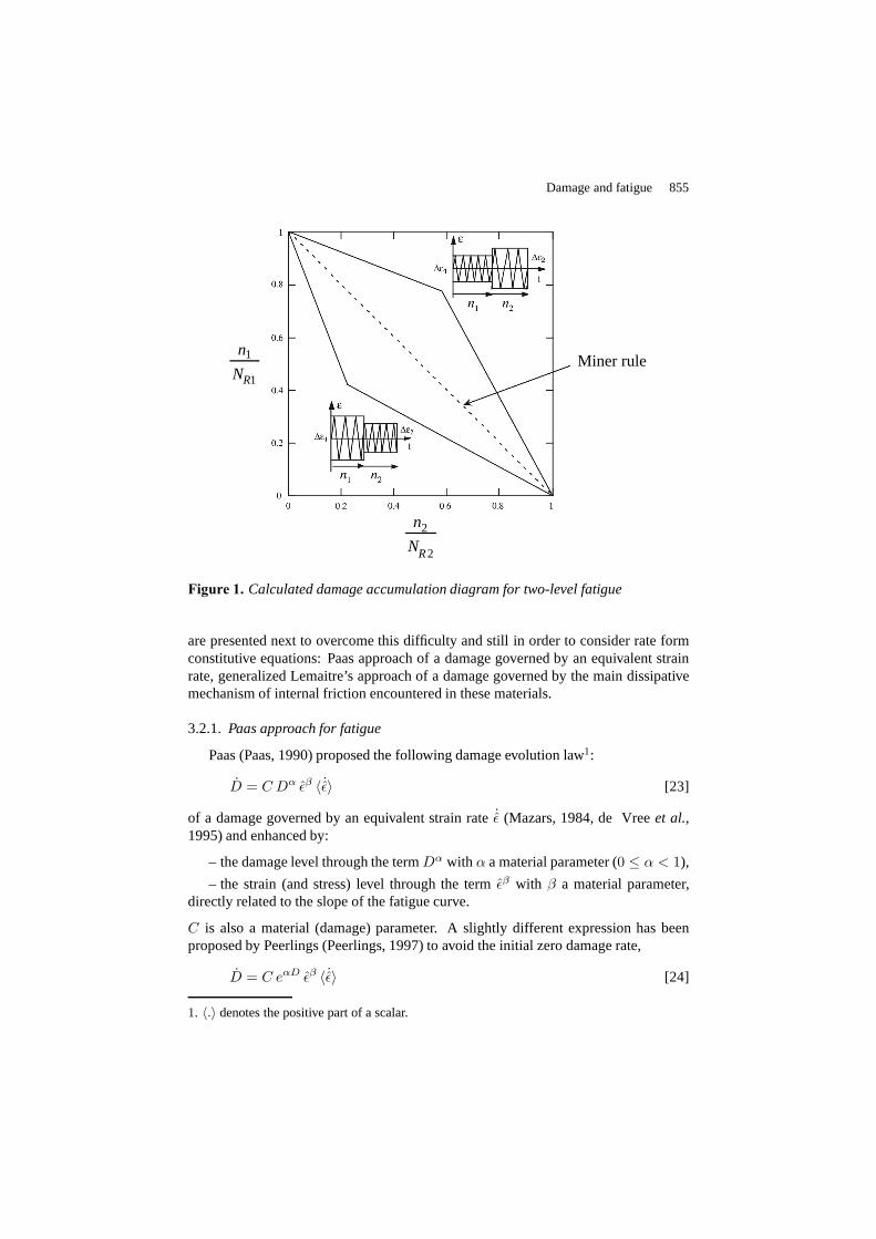
For two-level fatigue loading the consideration of a damagethreshold leads to a bi-linear damage accumulation diagram (Figure 1) more in accordance with experiments(Desmorat, 2000, Lemaitreet al.,2005).
Lemaitre’s damage law also applies to monotonic, creep and creep-fatigue failures(Lemaitre, 1992, Sermageet al.,2000, Lemaitreet al.,2005). For instance, the plasticstrain to rupture in tension is:
ǫpR ≈ ǫpD +
(
2ES
σ2u
)s
Dc [22]
3.2. Quasi-brittle materials
For quasi-brittle materials plasticity is often meaningless so that to consider dam-age growth governed by the accumulated plastic strain has nosense. Two approaches
Damage and fatigue 855
Miner rulen1
NR1
n2
NR2
Figure 1. Calculated damage accumulation diagram for two-level fatigue
are presented next to overcome this difficulty and still in order to consider rate formconstitutive equations: Paas approach of a damage governedby an equivalent strainrate, generalized Lemaitre’s approach of a damage governedby the main dissipativemechanism of internal friction encountered in these materials.
3.2.1. Paas approach for fatigue
Paas (Paas, 1990) proposed the following damage evolution law1:
D = C Dα ǫβ 〈 ˙ǫ〉 [23]
of a damage governed by an equivalent strain rate˙ǫ (Mazars, 1984, de Vreeet al.,1995) and enhanced by:
– the damage level through the termDα with α a material parameter (0 ≤ α < 1),
– the strain (and stress) level through the termǫβ with β a material parameter,directly related to the slope of the fatigue curve.
C is also a material (damage) parameter. A slightly differentexpression has beenproposed by Peerlings (Peerlings, 1997) to avoid the initial zero damage rate,
D = C eαD ǫβ 〈 ˙ǫ〉 [24]
1. 〈.〉 denotes the positive part of a scalar.
856 REGC – 10/2006. Geomechanics in energy production
The growth of damage and the fatigue life can be gained in closed form for thesituation of uniaxial loading between a zero minimum strainand a maximum strainequal to the (constant) strain amplitude∆ǫ, with the assumption that there is no fatiguelimit. A first integration over one cycle (assumingD constant on a cycle) gives theamplitude laws,
δD
δN= C Dα (∆ǫ)β+1
β + 1for Paas law
δD
δN= C eαD (∆ǫ)β+1
β + 1for Peerlings law
[25]
relations which can then be integrated as done in section 2 yielding the number ofcycles to ruptureNR as a function of the strain amplitude,
NR =(β + 1)D1−α
c
C(1 − α)(∆ǫ)β+1for Paas law
NR =(β + 1)(1 − e−αDc)
αC(∆ǫ)β+1for Peerlings law
[26]
which is in both cases a straight line of slope−(β + 1) in the log ∆ǫ vs logNR
fatigue diagram. Note that due to the multiplicative splitting between the damageenhancing termCDα orCeαD and the strain enhancing termǫβ , a linear accumulationis obtained for multi-level loading (Miner rule for two-level fatigue loading).
It is also tempting to apply Paas and Peerlings laws to monotonic loading, leadingthen to:
∫ Dc
0
D−αdD = C
∫ ǫR
0
ǫβdǫ for Paas law
∫ Dc
0
e−αDdD = C
∫ ǫR
0
ǫβdǫ for Peerlings law
[27]
and to the rupture strain corresponding toD = Dc,
ǫR =
[
(β + 1)D1−αc
(1 − α)C
]1
β+1
for Paas law
ǫR =
[
(β + 1)(1 − e−αDc)
αC
]
1β+1
for Peerlings law
[28]
which is in general not found equal to the measured rupture strain if the fatigue valuesof the material parametersC, α, β are considered. The Paas approach is then suitablefor fatigue, and will face difficulties to model failure due to severe overloads.
Damage and fatigue 857
3.2.2. Generalized damage law
The damage law [8] can be generalized as (stored energy damage threshold in-cluded):
D =
(
Y
S
)s
π as soon asws = wD [29]
in order to describe damage growth governed by the main dissipative mechanism(Cantournetet al., 2003, Lemaitreet al., 2005). It was plasticity (settingπ = p)for metals, elastic strains in previous section, it is internal sliding and friction for mostmaterials (as concrete but as also filled elastomers!). It needs an adequate definition ofthe cumulative measure of the internal slidingπ, definition which cannot be given hereas it is related to the chosen thermodynamics modeling for the material irreversibili-ties, for example a model with internal sliding and frictionfor concrete (section 4.4),Drucker-Prager plasticity model for rocks (see next section and also section 4.4).
Just to make a complete transition with Paas approach for fatigue, remark thatsettingπ = 〈ǫ〉 altogether withY = 1
2Eǫ2 andwD = 0 makes Equation [29] become
D =
(
Eǫ2
2S
)s
〈ǫ〉 =
(
E
2S
)s
ǫ2s〈ǫ〉 [30]
which is the caseC = (E/2S)s, α = 0, β = 2s of Paas and Peerlings laws.
3.3. Application to rocks
Mechanical behavior of rocks is often modeled by use of non associated plasticitysuch as by the classical Mohr-Coulomb and Drucker-Prager plasticity models leadingto a quite simple representation of dilatancy. Again, the definition of an equivalentplastic strain is dependent on the plasticity model, but twosomehow natural choicesfor π must be considered:
(a) the choice of damage governed by the equivalent shear plastic strain built fromthe deviatoric (shear) plastic strain rateǫǫǫpD = ǫǫǫp − 1
3 tr ǫǫǫp111,
γp =
∫
√
2
3ǫǫǫpD : ǫǫǫpDdt [31]
which is equal to the accumulated plastic strainp of von Mises plasticity.
(b) the choice of damage governed by the hydrostatic irreversible strain,
ǫpv = tr ǫǫǫp [32]
each choice leading to a different generalization of Lemaitre’s law:
(a) D =
(
Y
Sγ
)s
γp
(b) D =
(
Y
Sv
)s
ǫpv
[33]
858 REGC – 10/2006. Geomechanics in energy production
It seems difficult to make one expression prevail instead of another. One could arguethat damage is mainly governed by dilatancy and enhanced by the micro-defects open-ing (in accordance with damage law (b)) but by chance both laws will be found strictlyequivalent for Drucker-Prager plasticity (withSγ different fromSv, see section 4.4).
3.4. Micro-defects closure effect – Mean stress effect
For most materials, compressive loadings are less criticalthan tensile ones, at leastas long as structural instabilities do not take place. This is due to the phenomenon ofmicro-defects or micro-cracks closure when the material iscompressed. The damagerate in compression is then lower than the damage rate in tension. In fatigue, thisleads to the so called mean stress effect of the fatigue life reduction for a given stressamplitude but for increasing mean stressesσ = (σMax + σmin)/2. This is the stressratio effect of section 2 asσ = 1
2σMax(1+Rσ) and as then an amplitude law functionof ∆σ andRσ is equivalently function ofσMax andσ.
A damage law ensuring a damage rate smaller in compression than in tension (forthe same stress or strain level) will naturally model the mean stress effect. This willthen be the case with an adequate choice of equivalent strainǫ or energyY and ofexponentsβ or s. A possibility is to consider the following strain energy release ratedensity derived from thermodynamics assumptions2 (Ladevèzeet al.,1984, Lemaitre,1992)
Y =1 + ν
2E
[
〈σσσ〉+ : 〈σσσ〉+(1 −D)2
+ h〈σσσ〉− : 〈σσσ〉−(1 − hD)2
]
−ν
2E
[
〈tr σσσ〉2
(1 −D)2+ h
〈−tr σσσ〉2
(1 − hD)2
]
[34]
introducingh the microdefects closure parameter (0 < h < 1) and rewritten in thesimple uniaxial case
Y =〈σ〉2
2E(1 −D)2+ h
〈−σ〉2
2E(1 − hD)2[35]
so that for the same stress or strain level (in absolute value) it is aroundh times smallerin compression than in tension. Considering Lemaitre’s damage evolution law [8]gives a damage rate even smaller in compression as then:
Dcompression ≈ hsDtension << Dtension [36]
For metals, the damage increment per cycle betweenσmin < 0 andσMax > 0 is:
δD
δN≈
1
(2ES)s
[
σ2sMax
(1 −D)2+ h
σ2smin
(1 − hD)2
]
∆ǫp [37]
2. 〈.〉+ (resp.〈.〉−
) standing for the positive (resp. negative) part of a tensorin terms of principalvalues.
Damage and fatigue 859
leading to:
∫ D
0
[
1
(1 −D)2+ h
R2sσ
(1 − hD)2
]−1
dD =(∆σ)2s
(8ES)sN∆ǫp [38]
and to the representation of the mean stress effect in fatigue as:
NR =(8ES)sKq
cyc
(∆σ)2s+q
∫ Dc
0
[
1
(1 −D)2+ h
R2sσ
(1 − hD)2
]−1
dD [39]
3.5. Damage post-processing
For early design of mechanical components, the coupling of the strain behaviorwith the damage may be neglected and a post-processing of damage evolution is pos-sible after a classical structure analysis (Hayhurstet al.,1973). This approach is anuncoupled analysis, it is based on a reference nonlinear computation allowing withoutdamage representation for a correct estimation of the strain energy density and of ei-ther the accumulated plastic strainp or the cumulative measure of internal slidingπ.This analysis is efficient for ductile materials as metals (Lemaitre, 1992) or elastomers(Cantournetet al.,2003). It needs to be developed for other materials but note that itprobably won’t easily apply to concrete for which damage itself is the main cause ofthe stress-strain (softening) response so that the above reference calculation does notexist! In last case (when the coupling between strains and damage is strong) and alsofor accurate engineering applications a fully coupled analysis is necessary. The con-stitutive equations of the full damage model (see section 4)need to be implementedwithin a Finite Element computer code.
The post-processing consists in calculating the integral
D =
∫ t
tD
(
Y (t)
S
)s
π(t)dt [40]
from results of classical computations made without damage; it corresponds to theaposterioritime integration of the damage evolution law [8] or [29] or [33] wheretD isthe time at damage initiation, for plastic materials solution ofpD =
∫ tD
0p(t)dt, more
generally ofwD =∫ tD
0ws(t)dt (see section 3.1).
The time histories of the measure of internal slidingπ (often p), which needs aa priori definition or a constitutive modeling, and of the energy density release rateY are the necessary inputs for the damage post-processing. The time to mesocrackinitiation tR or, for cyclic loading, the corresponding number of cycles to mesocrackinitiationNR corresponds to the reach of the critical damageDc at the structure mostloaded point.
Note that the post-processing may take place at one point only, if known: themost loaded point, usually whereY is maximum. RewrittenY = σ⋆ 2/2E it is also
860 REGC – 10/2006. Geomechanics in energy production
where the damage equivalent stressσ⋆ = σeqR1/2ν is maximum. The post-processing
may also take place at different (chosen) Gauss points of a structure. In any case,the damage law being written in a rate form, the post-processing applies to complexloading, not necessary 1D nor cyclic, nor even isothermal.
3.6. Jump-in-cycles procedure
For fatigue loading periodic or periodic by blocks the previous calculations, stepby step in time, becomes prohibitive when the number of cycles becomes large (104,106, 108,. . . ). For that reason a simplified numerical method is needed which allowsto “jump” full blocks of ∆N cycles. The time integration of Equation [40] or the 3DFinite Element computation of a structure is performed overone cycle once in a whileand the computation time may be almost divided by∆N .
This “jump” in cycles procedure works as follows (Lemaitreet al.,1994).
1) Before any damage growth,i.e. up to the thresholdws = wD, run the com-
putation until a stabilized cycleNs is reached and letδπ
δN
∣
∣
∣
∣
Ns
(resp.δp
δN
∣
∣
∣
∣
Ns
) be the
accumulated internal sliding (resp. plastic strain) increment over this single cycle. As-sume then that during the number∆N of the next cycles,π or p remains linear versusthe number of cyclesN and calculate the number of cycles to be jumped∆N cyclesas
∆N =∆p
δπ
δN
∣
∣
∣
∣
Ns
or ∆N =∆p
δp
δN
∣
∣
∣
∣
Ns
[41]
where∆p is a given value which determines the accuracy of the procedure. For plasticmaterials,∆p ≈ pD/50 is a good compromise between accuracy and time cost.The accumulated plastic strain is updated as:
The stresses, strains, irreversible strains at the end of the cycleNs and the cumulativemeasure of internal slidingπ(Ns+∆N)) (resp. the accumulated plastic strainp(Ns+∆N)) are then the initial values for the computation of the first time increment of thecycle(Ns + ∆N + 1).
Repeat the jumps up to the occurrence of damage.
2) Once damage occurs, run first the computation at constant damage until a newstabilized cycleNs is reached. Calculate
- the incrementδπ
δN
∣
∣
∣
∣
Ns
orδp
δN
∣
∣
∣
∣
Ns
- the damage incrementδD
δN
∣
∣
∣
∣
Ns
Damage and fatigue 861
Assume again that during the number∆N of the next cyclesπ or p andD remainlinear versusN and calculate the number of cycles to be jumped as
∆N = min
∆p
δπ
δN
∣
∣
∣
∣
Ns
orδp
δN
∣
∣
∣
∣
Ns
,∆D
δD
δN
∣
∣
∣
∣
Ns
[43]
where∆D is a given value which determines the accuracy on the damage.Hereagain∆D ≈ Dc/50 is a good compromise between accuracy and time cost and take
∆p =(
SYMax
)s
∆D with YMax the maximum value of the energy densityY over the
cycleNs.
The accumulated internal sliding or plastic strain and the damage are finally up-dated as
π(Ns + ∆N) = π(Ns) +δπ
δN
∣
∣
∣
∣
Ns
∆N
or
p(Ns + ∆N) = p(Ns) +δp
δN
∣
∣
∣
∣
Ns
∆N
and
D(Ns + ∆N) = D(Ns) +δD
δN
∣
∣
∣
∣
Ns
∆N
[44]
The stresses, strains, plastic strains, at the end of the cycleNs, the accumulated inter-nal slidingπ(Ns +∆N) or plastic strainp(Ns +∆N) and the damageD(Ns +∆N)are then the initial values for the computation of the first time increment of the cycle(Ns + ∆N + 1).
4. Toward an unified modeling for damage and fatigue ?
The idea of an unified damage model for many materials is made possible bythe consideration of the generalized damage law [29],i.e. by assuming that dam-age is governed by the main dissipative mechanism, often internal sliding and fric-tion, through the cumulative measureπ. This kind of modeling applies to metals(Lemaitreet al.,1985, Françoiset al.,1993) for which internal slips are mainly dueto dislocations creation and evolution, but also to non metallic materials such as con-crete and elastomers (Desmoratet al.,2001, Cantournetet al.,2003, Lemaitreet al.,2005, Desmoratet al.,2006).
The present section is a synthetic thermodynamics presentation of in fact differentconstitutive models. For more details on the general damagemechanics thermody-namics framework refer to (Lemaitreet al.,1985) or (Lemaitreet al.,2005).
862 REGC – 10/2006. Geomechanics in energy production
4.1. Thermodynamics Variables
Defineǫǫǫπ, aaa, q andD as internal variables associated with−σσσπ , xxx, Q and−Y(see table 1). The physical meaning of these thermodynamicsvariables depends onthe type of material and of the physical dissipative mechanisms (see section 4.4). Thevariableǫǫǫπ stands for the irreversible strains. The couples of variables (Q, q) and(xxx,aaa) will represent hardening, isotropic and kinematic, of ductile materials, they willrepresent consolidations, also isotropic and kinematic, for quasi-brittle materials.D isthe damage variable and the energy densityY is the strain energy release rate density.
Table 1. State and associated variables
Mechanisms Type State variables AssociatedObservable Internal variables
whereW1 andW2 define the strain energy density andws = G(q) + 12Cx aaa : aaa the
stored energy density (Cx is a material parameter), function of the scalar variableqand of the tensorial variableaaa. The state laws are:
σσσ = ρ∂ψ
∂ǫǫǫ= (1 −D)
∂(W1 +W2)
∂ǫǫǫ
σσσπ = −ρ∂ψ
∂ǫǫǫπ= (1 −D)
∂W2
∂ǫǫǫ
xxx = ρ∂ψ
∂aaa=∂ws
∂aaa= Cx aaa
Q = ρ∂ψ
∂q=∂ws
∂q= G′(q)
Y = −ρ∂ψ
∂D= W1 +W2
[46]
Damage and fatigue 863
They naturally define the effective stressesσσσ, σσσπ such as the elasticity law written interms of strains and of effective stresses does not depend explicitly uponD (strainequivalence principle):
σσσ =σσσ
1 −D=∂(W1 +W2)
∂ǫǫǫ
σσσπ =σσσπ
1 −D=∂W2
∂ǫǫǫ
[47]
Use as dissipative potential:
F = f + Fx + FD [48]
where:
– f = ‖σσσπ − xxx‖ − Q− σs < 0 defines the reversibility domain,‖.‖ is a norm inthe stresses space (not necessary von Mises norm) andσs is the reversibility limit,
– the functionsFx =γ
2Cxxxx : xxx andQ = Q(q) = G′(q) model the internal sliding
nonlinearity.Cx andγ are the kinematic hardening or consolidation parameters,
– FD =S
(s+ 1)(1 −D)
(
Y
S
)s+1
is Lemaitre’s damage potential withS ands
the damage parameters. Note that another classical choice,for instance for quasi-brittle elasticity, is Marigo damage potentialf = FD = Y − κ(D) (Marigo, 1981).But such a choice does not apply to fatigue.
The evolution laws derive from the dissipative potential through the normality rule,
ǫǫǫπ = µ∂F
∂σσσπ=
µ
1 −D
σσσπ − xxx
‖σσσπ − xxx‖
q = −µ∂F
∂Q= µ
aaa = −µ∂F
∂xxx= µ
∂F
∂σσσ= (1 −D) ǫǫǫπ − γ aaa q
D = µ∂F
∂Y=
µ
1 −D
(
Y
S
)s
=
(
Y
S
)s
π
[49]
with µ a Lagrange multiplier given by the consistency conditionf = 0 and f = 0for non viscous materials or given by a viscosity law such as generalized Norton’slaw π = 〈f/KN〉N for viscous materials. The multiplierµ is equal to a norm of theinelastic strain rate as first equation of [49] leads to:
µ
1 −D=
q
1 −D= ‖ǫǫǫπ‖ [50]
This defines the expected cumulative measureπ of the internal sliding,
π =
∫ t
0
‖ǫǫǫπ‖ dt [51]
864 REGC – 10/2006. Geomechanics in energy production
which gives back the accumulated plastic strain as
p =
∫ t
0
‖ǫǫǫp‖von Misesdt =
∫ t
0
√
2
3ǫǫǫp : ǫǫǫp dt [52]
in von Mises plasticity.
The generalized damage evolution law derives from the last equation of [49]:
D =
(
Y
S
)s
π if π > πD
D = Dc −→ mesocrack initiation
[53]
whereπD is the damage threshold, generally equal to zero for quasi-brittle materials.Written D = (Y/S)π, it models a damage governed by the main dissipative mecha-nism, here internal sliding and friction (throughπ), and enhanced by the value of thestrain energy density (throughY ). Written π = (S/Y )D, it models the increasinginternal sliding due to damage accumulation. As the constitutive equations describingboth damage and internal sliding are fully coupled, the interpretation is of course acombination of both points of view: each phenomenon, damageor internal sliding,enhances the other one.
4.3. Positivity of the intrinsic dissipation
The generalized damage model satisfies the positivity of theintrinsic dissipationD = σσσ : ǫǫǫ− ρψ as
D = σσσπ : ǫǫǫπ −Qq − xxx : aaa+ Y D
=
(
σσσπ :∂F
∂σσσπ+Q
∂F
∂Q+ xxx :
∂F
∂xxx+ Y
∂F
∂Y
)
µ ≥ 0[54]
when the dissipation potentialF (σσσπ, Q,xxx, Y ;D) is a non negative convex function ofits argumentsσσσπ,Q, xxx, Y with F (000, 0,000, 0;D) = 0 and where the damageD acts asa parameter. Using the evolution laws, the intrinsic dissipation may also be rewritten:
D =
(
σs + σv +γ
Cxxxx : xxx
)
(1 −D)‖ǫǫǫπ‖ + Y D ≥ 0 [55]
with σv the viscous stress (vanishing for non viscous materials) such asf = σv forviscous internal sliding.
Damage and fatigue 865
0
4
8
12
16
1 2 3 4 λ
1
4λ
t
3
F/So (MPa)
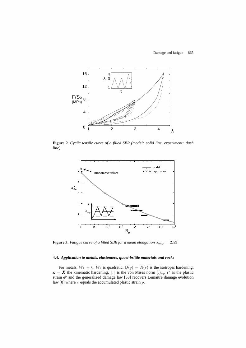
Figure 2. Cyclic tensile curve of a filled SBR (model: solid line, experiment: dashline)
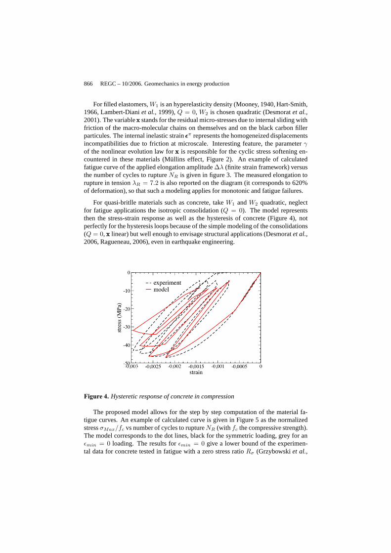
Figure 3. Fatigue curve of a filled SBR for a mean elongationλmoy = 2.53
4.4. Application to metals, elastomers, quasi-brittle materials and rocks
For metals,W1 = 0, W2 is quadratic,Q(q) = R(r) is the isotropic hardening,xxx = XXX the kinematic hardening,‖.‖ is the von Mises norm(.)eq , ǫǫǫπ is the plasticstrainǫǫǫp and the generalized damage law [53] recovers Lemaitre damage evolutionlaw [8] whereπ equals the accumulated plastic strainp.
866 REGC – 10/2006. Geomechanics in energy production
For filled elastomers,W1 is an hyperelasticity density (Mooney, 1940, Hart-Smith,1966, Lambert-Dianiet al.,1999),Q = 0, W2 is chosen quadratic (Desmoratet al.,2001). The variablexxx stands for the residual micro-stresses due to internal sliding withfriction of the macro-molecular chains on themselves and onthe black carbon fillerparticules. The internal inelastic strainǫǫǫπ represents the homogeneized displacementsincompatibilities due to friction at microscale. Interesting feature, the parameterγof the nonlinear evolution law forxxx is responsible for the cyclic stress softening en-countered in these materials (Müllins effect, Figure 2). Anexample of calculatedfatigue curve of the applied elongation amplitude∆λ (finite strain framework) versusthe number of cycles to ruptureNR is given in figure 3. The measured elongation torupture in tensionλR = 7.2 is also reported on the diagram (it corresponds to 620%of deformation), so that such a modeling applies for monotonic and fatigue failures.
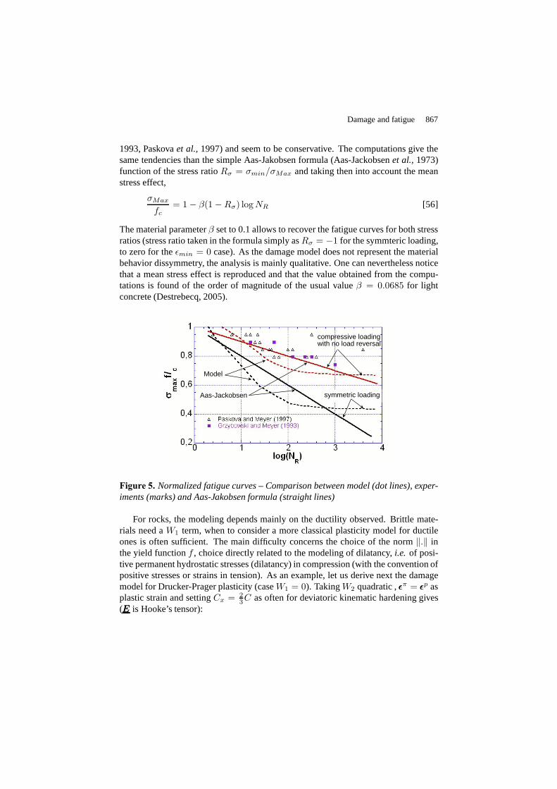
For quasi-britlle materials such as concrete, takeW1 andW2 quadratic, neglectfor fatigue applications the isotropic consolidation (Q = 0). The model representsthen the stress-strain response as well as the hysteresis ofconcrete (Figure 4), notperfectly for the hysteresis loops because of the simple modeling of the consolidations(Q = 0, xxx linear) but well enough to envisage structural applications (Desmoratet al.,2006, Ragueneau, 2006), even in earthquake engineering.
Figure 4. Hysteretic response of concrete in compression
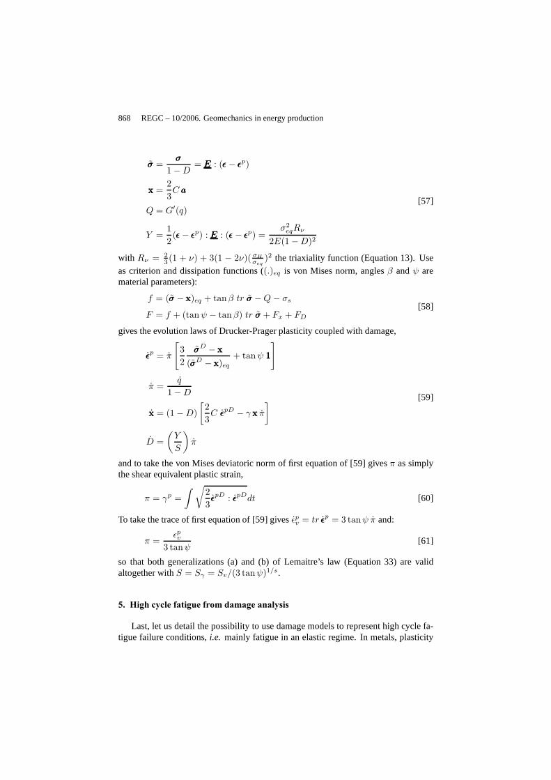
The proposed model allows for the step by step computation ofthe material fa-tigue curves. An example of calculated curve is given in Figure 5 as the normalizedstressσMax/fc vs number of cycles to ruptureNR (with fc the compressive strength).The model corresponds to the dot lines, black for the symmetric loading, grey for anǫmin = 0 loading. The results forǫmin = 0 give a lower bound of the experimen-tal data for concrete tested in fatigue with a zero stress ratio Rσ (Grzybowskiet al.,
Damage and fatigue 867
1993, Paskovaet al.,1997) and seem to be conservative. The computations give thesame tendencies than the simple Aas-Jakobsen formula (Aas-Jackobsenet al.,1973)function of the stress ratioRσ = σmin/σMax and taking then into account the meanstress effect,
σMax
fc= 1 − β(1 −Rσ) logNR [56]
The material parameterβ set to 0.1 allows to recover the fatigue curves for both stressratios (stress ratio taken in the formula simply asRσ = −1 for the symmteric loading,to zero for theǫmin = 0 case). As the damage model does not represent the materialbehavior dissymmetry, the analysis is mainly qualitative.One can nevertheless noticethat a mean stress effect is reproduced and that the value obtained from the compu-tations is found of the order of magnitude of the usual valueβ = 0.0685 for lightconcrete (Destrebecq, 2005).
Model
Aas-Jackobsen
compressive loadingwith no load reversal
symmetric loading
Figure 5. Normalized fatigue curves – Comparison between model (dot lines), exper-iments (marks) and Aas-Jakobsen formula (straight lines)
For rocks, the modeling depends mainly on the ductility observed. Brittle mate-rials need aW1 term, when to consider a more classical plasticity model forductileones is often sufficient. The main difficulty concerns the choice of the norm‖.‖ inthe yield functionf , choice directly related to the modeling of dilatancy,i.e. of posi-tive permanent hydrostatic stresses (dilatancy) in compression (with the convention ofpositive stresses or strains in tension). As an example, letus derive next the damagemodel for Drucker-Prager plasticity (caseW1 = 0). TakingW2 quadratic ,ǫǫǫπ = ǫǫǫp asplastic strain and settingCx = 2
3C as often for deviatoric kinematic hardening gives(EEE is Hooke’s tensor):
868 REGC – 10/2006. Geomechanics in energy production
σσσ =σσσ
1 −D= EEE : (ǫǫǫ− ǫǫǫp)
xxx =2
3C aaa
Q = G′(q)
Y =1
2(ǫǫǫ− ǫǫǫp) : EEE : (ǫǫǫ− ǫǫǫp) =
σ2eqRν
2E(1 −D)2
[57]
with Rν = 23 (1 + ν) + 3(1 − 2ν)( σH
σeq)2 the triaxiality function (Equation 13). Use
as criterion and dissipation functions ((.)eq is von Mises norm, anglesβ andψ arematerial parameters):
f = (σσσ − xxx)eq + tanβ tr σσσ −Q− σs
F = f + (tanψ − tanβ) tr σσσ + Fx + FD
[58]
gives the evolution laws of Drucker-Prager plasticity coupled with damage,
ǫǫǫp = π
[
3
2
σσσD − xxx
(σσσD − xxx)eq
+ tanψ 111
]
π =q
1 −D
xxx = (1 −D)
[
2
3C ǫǫǫpD − γ xxx π
]
D =
(
Y
S
)
π
[59]
and to take the von Mises deviatoric norm of first equation of [59] givesπ as simplythe shear equivalent plastic strain,
π = γp =
∫
√
2
3ǫǫǫpD : ǫǫǫpDdt [60]
To take the trace of first equation of [59] givesǫpv = tr ǫǫǫp = 3 tanψ π and:
π =ǫpv
3 tanψ[61]
so that both generalizations (a) and (b) of Lemaitre’s law (Equation 33) are validaltogether withS = Sγ = Sv/(3 tanψ)1/s.
5. High cycle fatigue from damage analysis
Last, let us detail the possibility to use damage models to represent high cycle fa-tigue failure conditions,i.e. mainly fatigue in an elastic regime. In metals, plasticity
Damage and fatigue 869
Thermo-elastic E, ν, α =αPlastic
Damage S, s, D
σy
µ = σ f
∞, C
µ
c
σijµ
(t) εijeµ
(t) εijpµ
(t)AAAAAARVE
microMESO
Thermo-elastic E, ν, α(Plastic σ
y, C
)
STRUCTURE CALCULATION
σ ij (t), ε ij (t),
Localization law
(ε ij (t ))pT(t),
T(t) D(t)
Plasticity and damage at microscale
Figure 6. Micro-element embedded in a thermoelastic RVE
then does not occurs at the mesoscale of the Representative Volume Element (RVE)of continuum mechanics but at a microscale, the defects scale. A two scale damagemodel has been build based on this feature (Lemaitreet al., 1994). It is a locallycoupled analysis, eventually with initial plastic strain and damage, which can be per-formed by post-processing an elastic computation. The jump-in cycles procedure ofsection 3.6 can advantageously be used.
5.1. Two scale damage model for metals
The two scales under consideration are represented in Figure 6. The mesoscopicscale or mesoscale is the scale of the RVE of continuum mechanics, the microscopicscale or microscale is the scale of the microdefects. At the mesoscale, the stresses aredenotedσσσ, the total, elastic and plastic strainsǫǫǫ, ǫǫǫe, ǫǫǫp. They are known from a thermo-elastic Finite Element computation with usually for high cycle fatigueǫǫǫp ≈ 0. Thevalues at the microscale have an upper-scriptµ. Plasticity and damage are assumedto occur at the microscale only,ǫǫǫpµ 6= 0, D ≥ 0, where for simplicity the damagevariable at the microscale has no upper-script (D = Dµ).
In order to illustrate the naturally ability of continuous damage to deal with com-plex loading, anisothermal conditions are assumed next so that the material parametersare temperature dependent and the thermal expansion, omitted so far, has to be intro-duced. The thermoelastic law for the RVE reads:
ǫǫǫ =1 + ν
Eσσσ −
ν
Etr σσσ 111 + α(T − Tref )111 [62]
with E the Young modulus,ν the Poisson ratio,α the thermal expansion coefficientandTref the reference temperature. The temperature field in the structure is usu-ally determined from an initial heat transfer computation.A law of thermo-elasto-plasticity coupled with damage is considered at microscale. The elasticity law readsthen (recall thatµ-upper-script stands for “variable at microscale”):
ǫǫǫµe =1 + ν
E
σσσµ
1 −D−ν
E
tr σσσµ
1 −D111 + αµ(T − Tref )111 [63]
870 REGC – 10/2006. Geomechanics in energy production
where the thermal expansion coefficientαµ is taken next equal to the meso coefficientα. In the yield criterion, the hardeningXXXµ is kinematic, linear, and the yield stress isthe asymptotic fatigue limit of the material, denotedσ∞
f ,
fµ = (σσσµ −XXXµ)eq − σ∞
f [64]
whereσσσµ = σσσµ/(1 − D) is the effective stress and wherefµ < 0 −→ elasticity.A linear kinematic hardeningXXXµ is considered at microscale (Fµ
x = 0). The set ofconstitutive equations at microscale is then:
ǫǫǫµ = ǫǫǫµe + ǫǫǫµp
ǫǫǫµe =1 + ν
Eσσσµ −
ν
Etr σσσµ111 + α(T − Tref )111
σσσµ = σσσµ
1−D
ǫǫǫµp =3
2
σσσµD −XXXµ
(σσσµ −XXXµ)eqpµ
d
dt
(
XXXµ
Cy
)
=2
3ǫǫǫµp(1 −D)
D =
(
Y µ
S
)s
pµ if pµ > pD
D = Dc −→ crack initiation
[65]
with the plastic modulusCy , the damage strengthS, the damage exponents and thecritical damageDc as material parameters. The damage evolution (last equation ofprevious set) is lower in tension than in compression due to the consideration of themicro-defects closure parameterh within Y µ as usually for metalsh ≈ 0.2 (Lemaitre,1992) and:
Y µ =1 + ν
2E
[
〈σσσµ〉+ : 〈σσσµ〉+(1 −D)2
+ h〈σσσµ〉− : 〈σσσµ〉−
(1 − hD)2
]
−ν
2E
[
〈tr σσσµ〉2
(1 −D)2+ h
〈−tr σσσµ〉2
(1 − hD)2
]
[66]
pµ is the accumulated plastic strain at microscale andpD the damage threshold (forloading dependent threshold see section 3.1 and refer to (Lemaitreet al.,2005)). Theplastic multiplierλ = pµ(1−D) is determined from the consistency conditionfµ = 0,fµ = 0.
The scale transition meso→ micro can be governed by different laws, the simplestbeing Lin-Taylor law of a strain at microscale identical to the strain at mesoscale(hypothesis used in initial two scale damage model and DAMAGE-90 post-processor):
ǫǫǫµ = ǫǫǫ [67]
For isothermal loading, Eshelby-Kröner loacalization law, based on Eshelby analysisof the spherical inclusion, is preferred (Eshelby, 1957, Kröner, 1961),
ǫǫǫµ = ǫǫǫ+ b(ǫǫǫµp − ǫǫǫp) [68]
Damage and fatigue 871
Eshelby’s analysis which leads, when damage and temperature coupling are takeninto account, to the modified (anisothermal) Eshelby-Kröner localization law (Seyediet al.,2004):
ǫǫǫµD =1
1 − bD
[
ǫǫǫD + b ((1 −D)ǫǫǫµp − ǫǫǫp)]
ǫµH =1
1 − aD[ǫH + a ((1 −D)αµ − α) (T − Tref )]
[69]
now used in DAMAGE-2005 post-processor, whereǫǫǫH = 13 tr ǫǫǫ andǫǫǫµH = 1
3 tr ǫǫǫµ
are the hydrostatic strains, respectively at mesososcale and at microscale, and wherea andb are the Eshelby parameters for a spherical inclusion,
a =1 + ν
3(1 − ν), b =
2
15
4 − 5ν
1 − ν[70]
200
250
300
350
102
103
104
105
106
107
TMax
NR
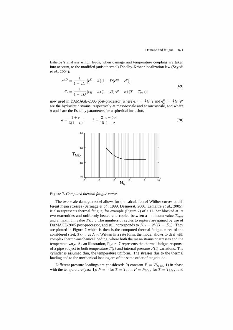
Figure 7. Computed thermal fatigue curve
The two scale damage model allows for the calculation of Wölher curves at dif-ferent mean stresses (Sermageet al., 1999, Desmorat, 2000, Lemaitreet al., 2005).It also represents thermal fatigue, for example (Figure 7) of a 1D bar blocked at itstwo extremities and uniformly heated and cooled between a minimum valueTmin
and a maximum valueTMax. The numbers of cycles to rupture are gained by use ofDAMAGE-2005 post-processor, and still corresponds toNR = N(D = Dc). Theyare plotted in Figure 7 which is then is the computed thermal fatigue curve of theconsidered steel,TMax vsNR. Written in a rate form, the model allows to deal withcomplex thermo-mechanical loading, where both the meso-strains or stresses and thetemperatue vary. As an illustration, Figure 7 represents the thermal fatigue responseof a pipe subject to both temperatureT (t) and internal pressureP (t) variations. Thecylinder is assumed thin, the temperature uniform. The stresses due to the thermalloading and to the mechanical loading are of the same order ofmagnitude.
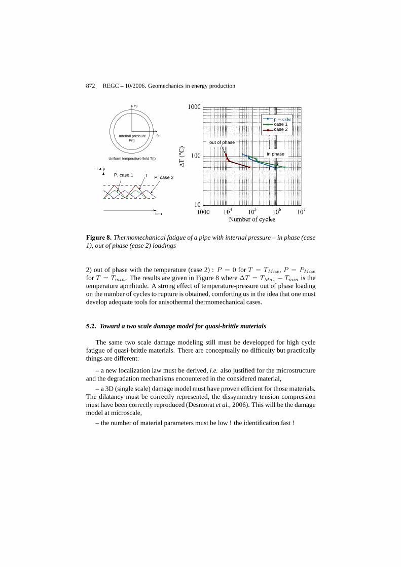
Different pressure loadings are considered: 0) constantP = PMax, 1) in phasewith the temperature (case 1):P = 0 for T = Tmin, P = PMax for T = TMax, and
872 REGC – 10/2006. Geomechanics in energy production
P(t)Internal pressure
Uniform temperature field T(t)
er
eθ
T P, case 2P, case 1
case 1case 2
out of phase
in phase
Figure 8. Thermomechanical fatigue of a pipe with internal pressure –in phase (case1), out of phase (case 2) loadings
2) out of phase with the temperature (case 2) :P = 0 for T = TMax, P = PMax
for T = Tmin. The results are given in Figure 8 where∆T = TMax − Tmin is thetemperature apmlitude. A strong effect of temperature-pressure out of phase loadingon the number of cycles to rupture is obtained, comforting usin the idea that one mustdevelop adequate tools for anisothermal thermomechanicalcases.
5.2. Toward a two scale damage model for quasi-brittle materials
The same two scale damage modeling still must be developped for high cyclefatigue of quasi-brittle materials. There are conceptually no difficulty but practicallythings are different:
– a new localization law must be derived,i.e. also justified for the microstructureand the degradation mechanisms encountered in the considered material,
– a 3D (single scale) damage model must have proven efficient for those materials.The dilatancy must be correctly represented, the dissymmetry tension compressionmust have been correctly reproduced (Desmoratet al.,2006). This will be the damagemodel at microscale,
– the number of material parameters must be low ! the identification fast !
Damage and fatigue 873
6. Conclusion
Lemaitre’s damage law has proven efficient for fatigue of metals. It can be gen-eralized intoD = (Y/S)sπ of damage governed by the main dissipative mechanismin order to apply to other materials, as concrete, elastomers or rocks. A few dam-age parameters are introduced, 2 for damage, the damage strengthS and the damageexponents, eventually 1 for a damage growth lower in tension than in compression,the micro-defects closure parameterh. Stress or strain amplitude laws as well as theWöhler curve of materials are calculated from the the time integration of the damagelaw. The stress triaxiality effect is taken into account, the mean stress effect recovered,qualitatively for quasi-brittle materials.
A unified damage model, coupling plastic or internal slidingirreversibilities withdamage, can then be build to recover the generalized damage law. It allows for therepresentation of both the hysteretic and the fatigue responses of materials. Also writ-ten in a rate form, it applies to the case of complex loading asnon cyclic (seismic,random fatigue...), non isothermal, non proportional loadings. High temperature dam-age behavior can also be addressed, as creep in the pioneering works of Kachanov(1958) and Rabotnov (1969) and creep-fatigue. More detailed application examplescan be found in (Lemaitreet al., 2005) or in present volume (Ragueneau, 2006) forstructures.
A lot of nice results have been obtained so far, applicationsare now needed toacquire engineering experience for designing structures with continuum damage me-chanics.
7. Bibliography
Aas-Jackobsen K., Lenshow R., “ Behavior of reinforced columns subjected to fatigue load-ing ”, ACI Journal, vol. 70, p. 199-206, 1973.
Aifantis E., “ The physics of plastic deformation ”,Int. J. Plasticity, vol. 3, p. 211-247, 1987.
Bodin D., Chabot A., de La Roche C., Pijaudier-Cabot G., “ A continuum damage approach ofasphalt concrete fatigue tests ”,15th ASCE Egnineering Mechancis Conference, June 2-5,Columbia University, New York, USA, p. 12-24, 2002.
Cantournet S., Desmorat R., “ Modélisation thermodynamique du frottement interne et del’hystérésis des élastomères, Thermodynamics modelling of internal friction and hystere-sis of elastomers ”,C. R. Mécanique, vol. 331, p. 265-270, 2003.
Chaboche J., Lesne P., “ A non-linear continuous fatigue damage model ”,Fatigue Fract. EngngMater. Struc., vol. 11, p. 1-17, 1988.
Chiarilli A.-S., Shao J., Hoteit N., “ Modelling of elasto-plastic damage behavior of claystone ”,Int. J. Plast., vol. 19, p. 23-45, 2003.
Conil N., Djéran-Maigre I., Cabrillac R., Su K., “ Modélisation du comportement mécaniquedes argilites de l’est ”,Revue Française de Génie Civil, vol. 8, p. 1135-1156, 2004.
874 REGC – 10/2006. Geomechanics in energy production
de Vree J., Brekelmans W., van Gils M., “ Comparison of nonlocal approaches in continuumdamage mechanics ”,Comp. Struct., vol. 55, p. 581-588, 1995.
Denoual C., Hild F., “ Dynamic fragmentation of brittle solids : a multi-scale model ”,Eur. J.Mech., A/Solids, vol. 21, p. 105-120, 2002.
Desmorat R., Modélisation et estimation rapide de la plasticité et de l’endommagement, Habil-itation à Diriger des Recherches, Technical report, Université Pierre et Marie Curie, 2000.
Desmorat R., Cantournet S., “ Thermodynamics modelling of internal friction and hysteresisof elastomers ”,Second European Conference on Constitutive Models for Rubber, Vienna,September 2001, 2001.
Desmorat R., Ragueneau F., Pham H., “ Continuum Damage Mechanics for hysteresis andfatigue of quasi-brittle materials and structures ”,Int. J. Num. Anal. Meth. Geomat., 2006.
Destrebecq J.,Comportement Mécanique du Béton (Traité MIM, série Matériaux de construc-tion), Lavoisier, Ed. J.M. Reynouard and G. Pijaudier-Cabot, chapter Fatigue du béton destructure, p. 255-294, 2005.
Dubé J. F., Modélisation simplifiée et comportement visco-endommageable des structures enbéton, PhD thesis, Université Paris 6, 1994.
Eshelby J. D., “ The determination of the elastic field of an ellipsoidal inclusion, related prob-lems ”,Proc. Roy. Soc., London, vol. A241, p. 376, 1957.
Fichant S., Laborderie C., Pijaudier-Cabot G., “ Isotropicand anisotropic descriptions of dam-age in concrete structures ”,Int. J. of Mechanics of Cohesive Frictional Materials, vol. 4,p. 339-359, 1999.
François D., Pineau A., Zaoui A.,Comportement mécanique des matériaux. Volume 2 : endom-magement, mécanique de la rupture, mécanique du contact, Hermès, 1993.
Gatuingt F., Pijaudier-Cabot G., “ Gurson’s plasticity coupled to damage as a CAP Model forconcrete compaction in dynamics ”,Constitutive Modelling of Geomaterials, CRC Press,p. 12-24, 2003.
Geers M., de Borst R., Peerlings R., “ Damage and crack modelling in single-edge and double-edge notched concrete beams ”,Engng. Fract. Mech., vol. 65, p. 247-261, 2000.
Godvindjee S., Simo J., “ A micro-mechanically based continuum damage model for carbonblack-filled rubbers incorporating Mullins effect ”,J. Mech. Phys. Solids, vol. 29, p. 87-112, 1991.
Grzybowski M., Meyer C., “ Damage accumulation in concrete with and without fiber rein-forcement ”,ACI Materials Journal, vol. 90, p. 594-604, 1993.
Gurson A. L., “ Continuum theory of ductile rupture by void nucleation and growth: Part I -Yield criteria and flow rules for porous ductile media ”,J. Engng Materials Technol., vol.99, p. 2-15, 1977.
Halm D., Dragon A., “ An anisotropic model of damage and frictional sliding for brittle mate-rials ”, European Journal of Mechanics, A/Solids, vol. 17, p. 439-60, 1998.
Hart-Smith L., “ Elasticity parameters for finite deformations of rubber-like materials ”,J. Appl.Phys., vol. 17, p. 608-625, 1966.
Hayhurst D., Leckie F. A., “ The effect of creep constitutiveand damage relationships uponthe rupture time of a solid circular torsion bar ”,J. Mech. Phys. Solids, vol. 21, p. 431-446,1973.
Damage and fatigue 875
Homand-Etienne F., Hoxha D., Shao J., “ A continuum damage constitutive law for brittlerocks ”,Computer and Geotechnics, vol. 22, p. 135-151, 1998.
Hua C., Socie D., “ Fatigue damage in 1045 steel under constant amplitude biaxial loading ”,Fatigue Eng. Mat. Struct., vol. 7, p. 165-179, 1984.
Jirasek M., “ Numerical modeling of strong discontinuities”, Revue Française de Génie Civil,vol. 6, p. 1133-1146, 2002a.
Jirasek M., “ Objective modeling of strain localization ”,Revue Française de Génie Civil, vol.6, p. 1119-1132, 2002b.
Jirasek M., “ Non-local damage mechanics with application to concrete ”,Revue Française deGénie Civil, vol. 8, p. 683-707, 2004.
Jirasek M., Zimmermann T., “ Embedded crack model: Part II: Combination with smearedcracks ”,Int. J. Num. Meth. Engng, vol. 50, p. 1291– 1305, 2001.
Kröner E., “ On the plastic deformation of polycrystals ”,Acta Metall., vol. 9, p. 155-161, 1961.
Laborderie C., Berthaud Y., Pijaudier-Cabot G., “ Crack closure effect in continuum damagemechanics: numerical implementation ”,Proc. 2nd Int. Conf. on ’Computer aided analysisand design of concrete strucutures’. Zell am See, Austria, 4-6 april, p. 975-986, 1990.
Ladevèze P., “ Modeling and simulation of the mechanical behavior of CMCs ”,High Temper-ature Ceramic-Matrix Composite, A. G. Evans and R. Naslain eds, Ceramic Transaction,vol. 57, p. 53-64, 1995.
Ladevèze P., Lemaitre J., “ Damage effective stress in quasiunilateral conditions ”,16th Inter-national Congress of Theoretical and Applied Mechanics, Lyngby, Denmark, 1984.
Lambert-Diani J., Rey C., “ New phenomenological behavior laws for rubbers and thermoplas-tic elastomers ”,Eur. J. Mech. A/Solids, vol. 18, p. 1027-1043, 1999.
Lemaitre J.,A Course on Damage Mechanics, Springer Verlag, 1992.
Lemaitre J., Chaboche J. L., “ Aspects phénoménologiques dela rupture par endommagement ”,Journal de Mécanique Appliquée, 1978.
Lemaitre J., Chaboche J. L.,Mécanique des matériaux solides, Dunod (english translation 1990“Mechanics of Solid Materials” Cambridge University Press), 1985.
Lemaitre J., Desmorat R., Sauzay M., “ Anisotropic damage law of evolution ”, Eur. J. Mech.,A/ Solids, vol. 19, p. 187-208, 2000.
Lemaitre J., Doghri I., “ Damage 90 : a post processor for crack initiation ”, Comput. MethodsAppl. Engng., vol. 115, p. 197-232, 1994.
Lemaitre J., Plumtree A., “ Application of damage concepts to predict creep-fatigue failures ”,J. Eng. Mat. Technol., vol. 101, p. 284-292, 1984.
Manson S. S., Hirschberg M.,Fatigue: An Interdisciplinary Approach, Syracuse UniversityPress, Syracuse, N.Y., 1964.
Marigo J., “ Formulation d’une loi d’endommagement d’un matériau élastique ”,C.R. Acad.Sci. Paris, série IIb, vol. 292, p. 1309-1312, 1981.
Mazars J., Application de la mécanique de l’endommagement au comportement non linéaire età la rupture du béton de structure, PhD thesis, Thèse d’Etat Université Paris 6, 1984.
876 REGC – 10/2006. Geomechanics in energy production
Mazars J., Berthaud Y., Ramtani S., “ The unilateral behavior of damage concrete ”,Eng. Fract.Mech., vol. 35, p. 629-635, 1990.
Mazars J., Pijaudier-Cabot G., “ From damage to fracture mechanics and conversely: A com-bined approach ”,Int. J. Solids Struct., vol. 33, p. 3327-3342, 1996.
Melenk J., Babuska I., “ The partition of unity finite elementmethod: Basic theory and appli-cations ”,Comp. Meth. Appl. Mech. Engng, vol. 39, p. 289-314, 1996.
Meschke G., Lackner R., Mang H., “ An anisotropic elastoplastic-damage model for plain con-crete ”,Int. J. Numer. Meth. Engng., vol. 42, p. 703-727, 1998.
Miehe C., Keck J., “ Superimposed finite elastic-viscoelasticplastoelastic stress response withdamage in filled rubbery polymers. Experiments, modelling and algorithmics implementa-tion ”, J. Mech. Phys. Solids, vol. 48, p. 323-365, 2000.
Mooney M., “ A theory of large deformations ”,J. Appl. Phys., vol. 11, p. 582-592, 1940.
Moës N., Dolbow J., Belytschko T., “ A finite element method for crack growth without remesh-ing ”, Int. J. Numer. Meth. Engng., vol. 46, p. 131-150, 1999.
Murakami S., Kamiya K., “ Constitutive and damage evolutionequations of elastic-brittle ma-terials based on irreversible thermodynamics ”,Int. J. Mech. Sci., vol. 39, p. 473-486, 1997.
Oller S., Onate E., Oliver J., Lubliner J., “ Finite element non linear analysis of concrete struc-tures using a plastic damage model ”,Engineering Fracture Mechanics, vol. 35, p. 219-231,1990.
Ortiz M., “ A constitutive theory for the inelastic behaviorof concrete ”,Mechanics of Materi-als, vol. 4, p. 67-93, 1985.
Paas M., Continuum damage mechanics with an application to fatigue, PhD thesis, EindhovenUniversity of Technology, The Netherlands, 1990.
Paas M., Schreurs P., Brekelmans W., “ A continuum approach to brittle and fatigue damage:theory and numerical procedures ”,Int. J. Solids Struct., vol. 30, p. 579-599, 1993.
Papa E., Talierco A., “ Anisotropic damage model for the multi-axial static and fatigue be-haviour of plain concrete ”,Engineering Fracture Mechanics, vol. 55, p. 163-179, 1996.
Paskova T., Meyer C., “ Low cycle fatigue of plain and fiber-reinforced concrete ”,ACI Mate-rials Journal, vol. 94, p. 273-285, 1997.
Peerlings R., Continuum Damage Modelling of Fatigue Crack Initiation. Internal report MT97.037, Technical report, Faculty of Mechanical Engineering, Eindhoven University ofTechnology, Eindhoven, The Netherlands, 1997.
Ragueneau F., “ Failure mechanisms of reinforced and pre-stressed concrete structures: Model-ing and computational aspects ”,Revue Française de Génie Civil, this volume, 2006.
Ragueneau F., Borderie C. L., Mazars J., “ Damage model for concrete-like materials couplingcracking and friction, contribution towards structural damping: first uniaxial application ”,Mechanics Cohesive Frictional Materials, vol. 5, p. 607-625, 2000.
Ramakrishnan V., Bremner T., Malhotra V., “ Fatigue Strength And Endurance Limit ofLightweight Concrete ”,Proceedings of the American Concrete Institute Symposium on"Performance of Lightweight Concrete", Eds., Thomas A. Holm and Alexander M. Vays-burd, Dallas, TX, November 14, p. 397-420, 1992.
Damage and fatigue 877
Resende L., “ A damage mechanics constitutive theory for theinelastic behaviour of concrete ”,Comp. Meth. Appl. Mech. Engng, vol. 60, p. 57-93, 1987.
Salari M., Saeb S., Willam K., Patchet S., Carrasco R., “ A coupled elastoplastic damage modelfor geomaterials ”,Computer Methods in Applied Mechanics and Engineering, vol. 193,p. 2625-2643, 2004.
Sermage J., Lemaitre J., Desmorat R., “ A two scale damage concept applied to fatigue ”,Int.J. Frac., vol. 97, p. 67-81, 1999.
Sermage J. P., Lemaitre J., Desmorat R., “ Multiaxial creep fatigue under anisothermal condi-tions ”, Fatigue and Fracture of Engng Mater. & Struct., vol. 23, p. 241- 252, 2000.
Seyedi M., Desmorat R., Sermage J., “ A two scale model for thermo-mechanical high cyclefatigue failure ”,European Conference on Fracture ECF 15, Advanced Fracture Mechanicsfor Life and Safety Stockholm, Sweden, 11-13 august, 2004.
Simo J., “ On a fully three-dimensional finite-strain visco-elastic damage model: formulationand computational aspects ”,Comput. Methods Appl. Mech. Engrg., vol. 60, p. 153-173,1987.
Tepfers R., Kutti T., “ Fatigue strength of plain, ordinary and light weight concrete ”,ACIJournal, vol. 76, p. 635-652, 1979.
Tvergaard V., Needleman A., “ Analysis of cup-cone fracturein a round tensile bar ”,ActaMetallurgica, vol. 32, p. 157-169, 1984.
Yazdani S., Schreyer H., “ Combined plasticity and damage mechanics model for plain con-crete ”,J. Eng. Mechanics, ASCE, vol. 16, p. 1435-1450, 1990.