° D Your supplier for COHLINE PRODUCTS CUTTING MACHINE Our single-phase and heavy pulling cutting machine reaches such a high turning point, that you can cut high pressure hoses up to DN 32 with the standard slit blade. Due to its lightweight of 20 kg this machine is also usable for the mobile use, under the condition that an electric power supply is available. In coordination with our skiving unit 9990.0004 you will be in the position to use the most popular hoses without contamination but with mobility. PB 9990.0003/07 DESCRIPTION working range: high pressure hoses up to DN 32, type 4 SH up to DN 25 Size / measurements: 400 x 510 x 540 mm weight: 20 Kg Drive: 2,2 kW Blade: 200 x 1,6 x 30 mm extraction connection: 40 mm max. outside: 52 mm Noise Level: 65 dBA ORDER-NO.: 9990.0003 Postfach/P.O.B. 12 41 D - 35662 DILLENBURG/GERMANY Automotive Fluid Handling Technologies Telefon/Phone 02771/399-0 - Telefax 02771/399-128 GmbH Internet: http://www.cohline.de e-mail: [email protected]Operating instructions Putting into operation: Fix the machine onto a stable device. Make sure the voltage of the power supply system and the machine are the same. The engine is protected by built in thermal contact against overheating. If overheating switch off the engine and restart. The restart protection prevent a unintentional start. Putting into operation is only possible to use again the start button. Cutting : With the retainer lock you have to adjust the correct guiding distance. If there is a big hose inside diametre resp. a big bend radius you have to adjust a big distance and if there is a small hose inside diametre resp. a small bend radius you have to adjust a small distance. The cutting of the hose without this preparation is dangerous and forbidden. You reduce friction and heating. The chart speed have to corresponding to the thickness of the material. Pull resp. push the hose regular in direction to the blade.Please avoid pushing and cut carefully. If you are cutting very big hoses, reduce the pressure on the hand lever and cut slowly. Attention! The blade can be glowing and breaking if you handling malpractices. A glowed out and deformed blade has to exchange immediately. After marking the cutting length the machine has to start by adjust the main switch on I. Fix the hose and push down the hand lever simultaneously without interruption. Maintenance: Before maintenance switch off the main switch and clean the machine from oil, fuel and/or other maintenance means. Please use fiber free clothes, but not aggressive detergent. Screwing connections please check and tighten. Against unchanged switch on during the maintenance guard with a warning sign. No welding or grinding on the machine without permission. Fire and explosion risk. Cleaning the machine daily with clothes and detergent (sprit). The blade is to control if there are breaches or other damages, the shell and the cables are to control if there are defects, also to control is if there are any unusual noise and vibrations and the machine is to keep dry. Weekly control the blade sharpness, if possible resharp resp. if need be exchange. The safety function of the blade protection pleae check. Attention ! The machine is to switch off. The blade protection should be carefully moving with minimal effort and with wering a chain glove in direction to the blade. The movement has to be constant and not to be jerky. If not you have to control the spring mechanism of the blade protection. The dismounting of the blade is to occur with the enclosed hook, to safe guard the blade against torsion. Always use a chain glove while working on the blade. The blade is extremely sharp! Loosen the screw/fastening srew with a spanner/hexagon socket in direction to the blade, remove the flanged wheel and take out the blade.. The mounting occur reserve. Attend on the concurring sense of rotation from the engine and the blade. If not concurring there is the danger of destroying of the blade during cutting.
Transcript
The Loop, Kent Int. Business ParkGB MANSTON KENT CT12 5DE
Automotive Fluid Handling Technologies
PB 9990.0002/2002
Tel. (018 43) 82 29 25 - Fax (01843) 82 29 24
(UK)LTD
A fully developed machine for the cutting of hoses with and without steel wire braidingsas well as removal from outer rubber layer at hydraulic hoses.A powerful special motor undertakes the drive.The specially finished blade cuts effortless all hoses up to c. 75 mm Ø.The grinding brush is bound in synthetic material and removes the outer rubber layer withoutany difficulties. The mandrels are adjustable in 2 levels through shifting support tacks.Out from that bending of the hose guarantees the longer life of the blade.TECHNICAL DATAS:Operating range: from DN 4 (3/16") up to DN 50 (DN 32 4 SP) (DN = inside diameter)Dimensions: length 650 mm, width 420 mm, height 750 (300) mmWeight: c. 65 kgElectro motor: 380 V 50 Hz 3 KW, 3000 Upm with protective switchBlade: special steel Ø 275 x 3 x Ø 30 mm HSSGrindingbrush: round brush with synthetic layer Ø 0,3, 70°Shore, Ø 200 x 24 x 43,5 mmextraction piece: Ø 80 mm (extraction unit 9990.0009 is available)ACCESSOIRIES:1 mandrel: size 4 (ø 4,5 mm)
order - no.: 9990.0002Your supplier for COHLINE PRODUCTS
TECHNICAL INSTRUCTIONS FOR 9990.0002TECHNICAL DATAS:FUNCTION:The direction of the rotation from the motor is up to down, i. e. the hose is pushed againstthe carving board during the cutting. To cut the hose you use the lever with as a pushdevice and blade protection. Because of the arrangement of the brush on the left side of themachine the turning direction will be reached, in which the wire coiling shows, thereforea sprouting of the wire braidings inside is prevented. The removal of the outer rubber layeris depending on the assemply instructions. The outer rubber layer can be removed accurateup to the braiding or coiling. As well it is possible to remove the outer rubber layer partly,apart from a rest layer.PUTTING INTO OPERATION:Fix the machineFix the blade and the brush and control it (if need be tighten up)Mains connection with CEE-type plug connector 16 Amps.Observe motor sense of rotation (if necessary, change phase wiring)Before restart, observe again knife and brush.CUT- AND BRUSH PROCESS:Cutting hose ware.Position hose on the cutting support so that the inner hose bending radius points toward theblade, then push forward toward the holding pins.The distance of the holding pins depends onthe hose ware diameter. small ø - small distance
large ø - large distanceGuide hose in one go against the blade. When separating, the cut should go apart, so that theblade will not jam on the sides - otherwise friction and heating of the blade.With heavy hose, reduce cutting pressure and observe motor speed.ATTENTION Improper working causes the blade to draw temper.
Re-sharpen the blade with a rubstone in regular intervals orsend us your blade to re-sharpen or order a new one
REMOVAL OF OUTER RUBBER LAYER:For top rubber removal put hose on the brush mandrels provided. The brush mandrels are held ina clamping device. The brush length is determined by movement in axial direction. Materialabrasion is continously adjustable with the star-handle tangential to the brush. Clamping leversligthly fastened, otherwise no tangentialadjustment possible.Afteradjustment, tightenclampinglever.MAINTENANCE:Remove mains plug !!Check blade and brush for defective parts.Remove protective hoods,clean machine.WEARING PARTS:Blade Ø 275 x 3 x ø 30,0 mmGrinding brush Ø 200 x 24 x ø 43,5 mm
D
Your supplier for COHLINE PRODUCTS
CUTTING MACHINE
Our single-phase and heavy pulling cutting machine reaches such a high turning point, thatyou can cut high pressure hoses up to DN 32 with the standard slit blade.Due to its lightweight of 20 kg this machine is also usable for the mobile use, under thecondition that an electric power supply is available.
In coordination with our skiving unit 9990.0004 you will be in the position to use the mostpopular hoses without contamination but with mobility.
PB 9990.0003/07
DESCRIPTION
working range: high pressure hoses up to DN 32, type 4 SH up to DN 25
Fix the machine onto a stable device. Make sure the voltage of the power supply system andthe machine are the same.The engine is protected by built in thermal contact against overheating. If overheating switch off theengine and restart. The restart protection prevent a unintentional start. Putting into operation is onlypossible to use again the start button.
Cutting :
With the retainer lock you have to adjust the correct guiding distance. If there is a big hoseinside diametre resp. a big bend radius you have to adjust a big distance and if there is a smallhose inside diametre resp. a small bend radius you have to adjust a small distance. The cuttingof the hose without this preparation is dangerous and forbidden. You reduce friction andheating. The chart speed have to corresponding to the thickness of the material. Pull resp. pushthe hose regular in direction to the blade.Please avoid pushing and cut carefully. If you arecutting very big hoses, reduce the pressure on the hand lever and cut slowly.Attention! The blade can be glowing and breaking if you handling malpractices.A glowed out and deformed blade has to exchange immediately.
After marking the cutting length the machine has to start by adjust the main switch on I.Fix the hose and push down the hand lever simultaneously without interruption.
Maintenance:
Before maintenance switch off the main switch and clean the machine from oil, fuel and/or othermaintenance means. Please use fiber free clothes, but not aggressive detergent. Screwingconnections please check and tighten. Against unchanged switch on during the maintenanceguard with a warning sign. No welding or grinding on the machine without permission. Fire andexplosion risk.
Cleaning the machine daily with clothes and detergent (sprit). The blade is to control if thereare breaches or other damages, the shell and the cables are to control if there are defects, alsoto control is if there are any unusual noise and vibrations and the machine is to keep dry.
Weekly control the blade sharpness, if possible resharp resp. if need be exchange. The safetyfunction of the blade protection pleae check. Attention ! The machine is to switch off.The blade protection should be carefully moving with minimal effort and with wering a chainglove in direction to the blade. The movement has to be constant and not to be jerky. If not youhave to control the spring mechanism of the blade protection.
The dismounting of the blade is to occur with the enclosed hook, to safe guard the bladeagainst torsion. Always use a chain glove while working on the blade. The blade is extremelysharp! Loosen the screw/fastening srew with a spanner/hexagon socket in direction to theblade, remove the flanged wheel and take out the blade.. The mounting occur reserve. Attendon the concurring sense of rotation from the engine and the blade. If not concurring there is thedanger of destroying of the blade during cutting.
PB 9990.0006/2004
Your supplier for COHLINE PRODUCTS
Hose Assembly Test Bench
PART-NO.: 9990.0006
Environmental requirements, product liability and upward wishes to quality fromyour customers lead more and more to higher demands by manufacture.A hose line, which ist not resistant to high pressure load, could be very expensiveoften even more expensive than the cost-value of a hose assembly test bench.Therefore, why risk some unnecessary?By checking your quality, certainly you avoid the lowest risk in future.Safe and efficient end control from hose lines will be a problem-free and quick matter.Take note particularly of the entire closed environmental space chamber, the safety valve- By opening the covering cap automatic pressure suppression within 1/10 secondstook place, rapid filling and automatic ventilation of the test pieces, weight relievingcovering cap with safety washers, ecologically friendly water-oil-emulsion as test mediumand the easy, problem-free operation.Also possible is the static pressure test from other hydraulic fittings, like i.e. valves,hydraulic cylinders, cases, couplings and further components.
The Loop, Kent Int. Business ParkGB MANSTON KENT CT12 5DE
Automotive FluidHandling Technologies
Tel. (018 43) 82 29 25 - Fax (01843) 82 29 24
(UK)LTD
Description:working range: from DN 06 up to DN 50proof pressure: to 1300 baractuation: pneumatical pressure intensifierdisplaced volume: 1,1 l/minaccessory drive: 0,38 kW 400 V-50 Hz-3 Phconnected load: air pressure 7 bar, ca. 20NI/min.pressure balance: automaticallytest medium: water-oil-emulsiontank: 100 litreflood pump: 4,5 l/min.dimensions test chamber: 1590 x 795 x 370 mmdimensions test bench: 2210 x 950 x 1325 mmweight: 210 kg (without filling)noise level: 72 dBA
accessories:plug-O adaptor set, metricplug-O adaptor set, english sizewater-oil-emulsionvacuum filter 100 µmair pressure maintenance unit
PB 9990.0011/2002
Your supplier for COHLINE PRODUCTS
Service Hose Press with hand pump
order-no. 9990.0011
Description:working range: all hose qualities from 1 PTFE, 1 SHP, 2 SHP, 2 TE, 3 TE, 1 SN,
2 SN up to DN 32, 4 SP up to DN 16 and 4 SH up to DN 25dimensions: length 500 mm, width 420 mm, height 440 mmweight: approximately 32 kgpress die set: 8 piecesmax. die length: 75 mmpressing force: 900 KN ( 90 t )oil content: 5 l hydraulic oil HLP 22, DIN 51524
or Tellus 22 from SHELLAccessories: each 1 press die set for DN 5/6 Ø 17, DN 8/10 Ø 20,
press die setDN 13/16 Ø 24 = order-no. 9990.0051.131651
The manual service hose press, distinguished through lower weight, high press powerand mobility (well portable). The hydraulic press will be installed on the front edge of theworkbench so that the work piece could be put in free at the front or if need be at the backand well accessible from all sides for maintenance works.To press the hose fittings on the prepared hose end the corresponding press dies arenecessary.All press die sets are marked with the minimum swaging diameter and could be falled of0,4 mm. The diameter results from a total closed press tool. The press stroke adjustmentfor the considered swage diameter you could take out from the respective skive and swagediameter chart.The working range is from DN 04 up to DN 32, except 4 SP up to DN 16 and for 4 SHup to DN 25. All hydraulic hoses could be pressed perfectly. The eight press die toolworks with tolerance balance. The press stroke is fully adjustable and will be given on themicrometer scale. The precision micrometer with one red stop lamp guarantees an exactindication of the swage diameters. Easy, fast re-setting, lubricant free and low in themaintenance.
The Loop, Kent Int. Business ParkGB MANSTON KENT CT12 5DE
Automotive Fluid Handling Technologies
Tel. (018 43) 82 29 25 - Fax (01843) 82 29 24
(UK)LTD
OPERATING INSTRUCTIONS for 9990.00111. Convert and adjust of the swage diameter
For the wanted DN insert the press ring in the appropriate press die set acccording tothe respective skive and swage diameter chart. The press dies, which are still in thetool, take out by hand with a slight turn from the open tool and then put in the abovedetermined press dies. Basic numbers of each press die must be visible in front.Now, the press stroke is to adjust on the micrometer.On the fixed scale piece are the mm, on the rotating spindle the tenth mm of the press strokegiven.Example: Type 4064. .1000
swage diameter Ø 21,2 mmpress die with the mark "Ø 20" DN 8/10adjustment 21,2 mm - 20,0 mm = 1,2 mm scale adjustment
2. Pressing of hose linesAfter the valve of the hand pump is closed, the hose line, which is to press, is insertedfrom behind into the press tool and is brought into press position, the hand pump willbe operated. The socket must be stand approx. 1,5 mm below press die upper edgeto avoid a collar at the upper end of the socket.Tolerance of each swage diameter - 3/10.The hand pump will be operated so long until the optic swage diameter indication lightsup. The valve of the hand pump will be opened now again, therefore also the press toolwill be opened and the pressed hose line will be released.
3. Check the swage diameterAfter the first pressing, check the swage-Ø according to the details of the respectiveskive and swage diameter chart. Is a correction necessary, the press micrometer isto adjust new. The swage diameter will be measured in the middle of the socket betweenthe press frames.
4. MaintenanceCarry out the oil change annually.Carry out the first oil change after 50 operating hours respectively 6 month.According to demand we recommend to clean the machine from cinder (metal abrasion)weekly and an oil control weekly.Ventilation of the hydraulic system through serveral openings and closings of thepress tool.Attention !If machine is not operated in accordance with this operation instruction, all warranty termsare automatically terminated. This also applies if other than prescribed lubricants havebeen used.Please pay attention to the safety rules.To operate the machine is allowed only by introduced persons.Danger! Improper operating of the press may cause crimping injuries of hands.Technical alterations reserve!
PB 9990.0012/2003
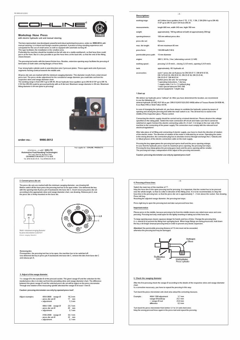
Workshop Hose Presswith electric hydraulic unit and manual steering
order-no.: 9990.0012
The here represented, new developed, powerful and robust workshop hose press, order-no. 9990.0012, withmanual steering, is in inland and foreign countries patented. A product of long-standing experience andconcipated for the use of small series as well as equiped with automatic turning off.This type facilitates the installation in the smallest area.Preferably the machine should be installed on the left side on a stable workbench, so that hose lines couldput in at the front. But it is also possible to put the hose lines at the back left, so that the end of the fittingshows forward.The pressing tool works with the lowest friction loss. Besides, extensive opening ways facilitate the pressing ofbent tubes on both sides and big flanges of hose lines.Four strong hydro cylinder work in axial direction onto 2 pressure plates. These again work onto 8 pressuresegments moving centrical towards the middle axle.All press die sets are marked with the minimum swaging diameter. This diameter results from a total closedpress tool. The press stroke adjustment for the considered swage diameter you could take out from therespective skive and swage diameter chart.The working range is from DN 4 up to DN 40. All our hydraulic hose qualities up to DN 40 (4 SP up to DN 16,4 SH the DN 20) could be pressed perfectly with an 8 die tool. Maximum swage diameter is 58 mm. Maximumfitting diameter is 64 mm (prior to pressing)
Your supplier for COHLINE PRODUCTS
The Loop, Kent Int. Business ParkGB MANSTON KENT CT12 5DE
Automotive Fluid Handling Technologies
Tel. (018 43) 82 29 25 - Fax (01843) 82 29 24
(UK)LTD
Description:workingrange: all Cohline hose qualities from 2 TE, 3 TE, 1 SN, 2 SN (DN 4 up to DN 40)
4 SP up to DN 16 and 4 SH from DN 20measurements: length 660 mm, width 540 mm, hight 780 mmweight: approximately 160 kg without oil (with oil approximately 200 kg)opening distance: 100 mm without press diespress die set: 8 piecesmax. die length: 60 mm-maximum 85 mmpress force: 130.000 daN (130 t)permissible press path: 15 mm diameterengine: 380 V, 50 Hz, 3 kw ( alternating current 2,2 kW)working speed : pressing 3,5 Ø mm/s , closing 3,5 Ø mm/s, opening 5,9 Ø mm/stank: approximately 40 l hydraulic oilaccessories: each 1 press die set 8 pieces for DN 5/6 Ø 17, DN 8/10 Ø 20,
DN 13/16 Ø 24, DN 20 Ø 32, DN 25 Ø 36, DN 25 Ø 40,DN 32 Ø 47 DN 40 Ø 54further press die sets for surcharge1 operating instructions, 1 die key,1 supply cable 3 m 5 x 1,5 without plug1 tube special lubricant OKS 260special equipment: 1 depth stop
1.Start upWe deliver our hydraulic press "without" oil. After you have determined the location, we recommendto use the following oil :mineral-hydraulic oil SAE-HLP 46 as per DIN 51524/51525 (ISO 4406) either of Texaco Rando Oil HDB 46,Esso Nuto H46 or Shell Tellus Oil 46.In case of changing the hydraulic oil, you have always to ventilate the hydraulic system by means ofopening and closing the pressing tool while the main switch is on. The oil level has to stand in themiddle of the inspection glass. Please control.Connecting the electric supply should be carried out by a trained electrician. Please observe the voltagespecified on the rating plate. Switch the main connection off-circuit and make sure that it cannot beswitched on again.Connect the electric connecting cable (4 x 4 mm², 3 m long) on the rear side of themachine to the connecting of the power supply.The connection must comply with the relevant localelectrical regulations!After take place of oil filling and connecting of electric supply, you have to check the direction of rotationof the electric motor. The direction of rotation of the motor is indicated by an arrow. Operating the motorin the wrong direction, the connection plug has to absolute reverse through exchange the L1 (black) andL2 (blue) phases of the electric connection cable on the main supply.Pressing the key open press the pressing tool opens itself and the press opening enlarge.In case that the hydraulic press reach its maximum press opening, the pressing tool stops.Pressing the key close press the pressing goes back and the press opening will be smaller.The pressing tool stops, independent of the adjust of the pressing micrometer.Caution: pressing micrometer use only by opened press tool!
- 2 -
2. Convert press die setThe press die sets are marked with the minimum swaging diameter, see drawing left.Before switch off the hose press the pressing tool has to be open entire. Use delivered die keywith the opening hole B press pin A backwards into base die C. Insert necessary press die setaccording to the appropriate skive and swage diameter chart, see drawing. Release pin A, nowthe press die is firmly mounted on the base die.
Adjust examples: 4054.0800 swage-Ø 18,3 mm- press die set-Ø 17 mm= adjustment 1,3 mm
4064.1300 swage-Ø 23,7 mm- press die set-Ø 20 mm= adjustment 3,7 mm
4184.2000 swage-Ø 35,1 mm- press die set-Ø 32 mm= adjustment 3,1 mm
The swage-Ø is the outside-Ø of the pressed socket. The given swage-Ø and the selection for thisneeded press dies is to take out from the prevailing skive and swage diameter chart. The differencebetween the given swage-Ø and the selected press die set will be adjust on the press micrometer.Through one rotation of the measuring spindle alterated the swage-Ø of exact 1 mm Ø.Caution: pressing micrometer use only by opened press tool!
3. Adjust of the swage diameter
RemovingdiesPrerequisites: the pressing tool has to be open, the machine has to be switched off.Use delivered die key to press pin A backwards into base die C, remove the dies from base die Cand release pin A.
Ø32
Mark=minimumswaging diameter
by press micrometer-scala 0,0 !
(lowest swaging diameter)
- 3 -4. Pressing of hose linesSwitch the main key of the machine of "I".Inlay the hose line in the open pressing tool for pressing. It is important, that the socket has to be pressedover the whole length, so that no collar in direction of the fitting arise. It is to be recommended, to inlay thehose line in the pressing tool, so that the press die set is approximately 1 - 2 mm above the socket. See drawing.Press left key.Reaching the adjusted swage diameter, the pressing tool stops.Press right key to open the pressing tool and take out pressed hose line.Important noticePlease press in the middle, because pressing to far from the middle means one-sided more wear and conepressing. Pressing tool only small open for the lightly inserting or taking out of the hose line.To large opening ways means squeeze danger for hands and loss of time. Change the pressing time(i. e. extend it) to prevent the fitting from springing back. When large fittings are being processed, hold downthe key a bit longer (manual pressing time) in order to prevent any elastic expansion.Attention! the permissible pressing distance of 15 mm must not be exceeded,otherwise the pressing tool may be damaged.
5. Check the swaging diameterAfter the first pressing check the swage-Ø according to the details of the respective skive and swage diameterchart.Is a correction necessary, you have to repeat the pressing in this way:Turn back the press micrometer anti-clock wise about the correcting measure.Example: 4064.1300adjustment 3,7 mm
swage-Øhandicap 23,7 mm= swage-Ø real 24,0 mmdifference 0,3 mm
Turn back the press micrometer from before 3,7 to 3,4 anti-clock wise.Inlay the wrong pressed hose again in the press tool and repeat the pressing.
- 4 -
6. Adjust the depth stopAs special accessory the hose press is supplied with a depth stop located at the back of the press tool.It is used to ensure a secure and simple insertion of the hose line during pressing processes of small andmedium series applications.First press hose line on one side without depth stop. As long as pressed side of hose line is still betweenthe dies the depth stop cone must moved against it and secured with a knurled screw.Now the second side can be pressed using the depth stop.7.Safety/HazardsTo operate the machine is allowed only by an introduced person.Only for pressing hose lines. For other uses please keep consultation.Danger: never reach into the pressing tool with your hands while the electric motor is running!Always make sure that there is an adequate safety distance of at least 120 mm to the pressing tool when youinsert a hose assembly!Always disconnect the machine from the power supply whenever maintenance work has to be carried out oradjustments have to be made.8. MaintenanceYou have to remove daily any metal rubbed off from the pressed fittings with compressed air.Change the hydraulic oil annually.Oil filling see point 1. start up
Changing the slide bearingsThe changing must be carried out through two persons.Remove the screws of the casing and put them aside.Remove the 5 hexagon screws at the front of the casing and take them off.Push the two flat levers (screw driver) each left and right of the respective base die under the pressure springs.Lever the pressure springs up carefully.Now, the second person pulls out the store bearing in front and the store bearing behind under the base die.Afterwards, clean the guiding groove (brush, rag).Now, insert a new slide bearing.Renew all store bearings one after another. 8 store bearings in front and 8 behind.Pay attention to potential compensation bearings below the slide bearings.If they are available, they have been put again under the respective new slide bearings.When required change the dirt scrapers on the three lower base dies in front and behind.They are available in the spare part-set.After changing mount the casing again.9. Adjusting the pressing micrometerLoosen the screws on the backside of the casing and put them aside.Loosen the locknut of the contact screw.Turn the contact screw out to increase the pressing size, turn the contact screw in to reduce the pressing size.Tighten the locknut of the contact screw again.Mount the cover of the pressing micrometer´s housing again.Switch on the machine and check the pressing size when the pressing micrometer is set to zero.Repeat the adjusting procedure if there is still a measureable deviation from the pressing size of the pressing die.
- 5 - PB 9990.0013/2003
Workshop Hose Presswith electric hydraulic unit
order-no.: 9990.0013
The here represented workshop hose press, order-no. 9990.0013 is a product of long-standing experience.The modern compact type design facilitates the installation in every pleasant working heigth in the smallestarea. Through a new system a press force of 240.000 daN (240t) will be reached, so that all our hydraulic hosequalities up to DN 50 4 SH could be pressed perfectly.The pressing tool works with the lowest friction loss.Besides, extensive opening ways facilitate the pressing of bent tubes on both sides and big flanges of hose lines.The eight press die tool works with tolerance balance. The press stroke is fully adjustable and will be given onthe micrometer scale.All press die sets are marked with the minimum swaging diameter. This diameter results from a total closed presstool. The press stroke adjustment for the considered swage diameter you could take out from the respective skiveand swage diameter chart. The working range is from DN 4 up to DN 50. All our hydraulic hose qualities up to DN50 could be pressed perfectly with an 8 die tool.The precision micrometer with one red stop lamp guarantees an exact adjustment and indication of the swagediameters. Easy, fast re-setting and low in the maintenance.The sliding faces of the press dies will be lubricated with enclosed lubricant from time to time..
Description:workingrange: all hose qualities from 2 TE, 3 TE, 1 SN, 2 SN, 4 SP and 4 SH DN 4 up to DN 50measurements: length 650 mm, width 270 mm, hight 425 mmweight: approximately 77 kgopening distance: 100 mmpress die set: 8 piecesmax. die length: maximum 100 mmpiston force: 80.000 daN (80 t)press force: 240.000 daN (240 t)permissible press path: 8 mm diameterengine: 380 V, 50 Hz, 1,3 kw ( other voltages for extra costs)oil content: approximately 0,9 l hydraulic oil HLP 36/45 from Total or Tellus 22 from Shell
delivery with oil, to start pressing interchange locking screw at tank(transportationsecurity)
Accessories: each 1 press die set 8 pieces for DN 5/6 Ø 17, DN 8/10 Ø 20, DN 13/16 Ø 24,DN 20 Ø 32, DN 25 Ø 36, DN 25 Ø 40, DN 25 Ø 47, DN 32 Ø 501 operating instructions, 1 feed cable 3 m 5-lead without main plug1 tube special lubricant OKS 260
The Loop, Kent Int. Business ParkGB MANSTON KENT CT12 5DE
Automotive Fluid Handling Technologies
Tel. (018 43) 82 29 25 - Fax (01843) 82 29 24
(UK)LTD
OPERATING INSTRUCTIONS for 9990.00131. Convert and adjust of the swage diameter
For the wanted DN insert the press ring in the appropriate press die set acccording to the respectiveskive and swage diameter chart. Insert the press dies from top in the mortise of the press ring.Basic numbers of each press die must be visible from above.The press stroke is to adjust on the micrometer. On the fixed scale piece are the mm, on therotating spindle the tenth mm of the press stroke given.Example: Type 4064. .1000
press die with the mark "Ø 20" DN 8/10 socket Ø 24,9 mm, swage diameter Ø 21,0 mm
adjustment 24,9 mm - 21,0 mm = 3,9 mm scale adjustment2. Pressing of hose lines
Insert the pressing hose line in the press ring from bottom to top. In press position, that meanswhile the press ring is screwed in clockwise, you have to look from top how the press dies standto the socket. The socket must be stand approx. 1,5 mm below press die upper edge to avoida collar at the upper end of the socket.Tolerance of each swage diameter - 3/10.After the hose line is keeping from the press ring, push green START button. If swage diameteris reached the red STOP button lightens up for control and the machine stops automatically.Hose line is opened from the tool.
3. Check the swage diameterAfter the first pressing, check the swage-Ø according to the details of the respectiveskive and swage diameter chart. Is a correction necessary, the press micrometer is to adjustnew.Scale spindle adjust 0 and the corrigated measure adjust new.Example: swage diameter handicap 23,5 mm - real 24,0 mm
new adjustment: 0,5 mmThe swage diameter will be measured in the middle of the socket between the pressframes.
4. Adjusting the press micrometerAdjusting the press micrometer turn-off machine at main switch and remove main plug.Remove front plate. Loosen counter nut and contact screw. Enlarge swage diameter = loosencontact screw, diminish swage diameter = tighten contact screw. Remount front plate. Installmains operation. Turn-on machine and control press value.
5. MaintenanceAfter approx. 100 pressings lubricate bearing surface only with Anti-Size Loctite.Lubricate the press ring with machine oil only. We recommend to change the hydraulic oil annuallyand to clean the tool surface semi-annually.Attention !If machine is not operated in accordance with this operation instruction, all warranty termsare automatically terminated. This also applies if other than prescribed lubricants havebeen used. Do not use Tri, Per fluids or similar in the piston room.Please pay attention to the safety rules.To operate the machine is allowed only by introduced persons.Danger! Improper operating of the press may cause crimping injuries of hands.
Technical alterations reserve!
PB 9990.0014/2002
Workshop Hose Presswith electric hydraulic unit and manual steering
order-no.: 9990.0014
The here represented, new developed, powerful and robust workshop hose press, order-no. 9990.0014, withmanual steering, is in inland and foreign countries patented. A product of long-standing experience andconcipated for the use of small series as well as equiped with automatic turning off.This type facilitates the installation in the smallest area.Preferably the machine should be installed on the left side on a stable workbench, so that hose lines couldput in at the front. But it is also possible to put the hose lines at the back left, so that the end of the fittingshows forward.A compact tool makes sure, that the enormous high press power of 240 tons works in at the work piece.The pressing tool works with the lowest friction loss. Besides, extensive opening ways facilitate the pressingof bent tubes on both sides and big flanges of hose lines.All press die sets are marked with the minimum swaging diameter. This diameter results from a total closedpress tool. The press stroke adjustment for the considered swage diameter you could take out from therespective skive and swage diameter chart.The working range is from DN 4 up to DN 80. All our hydraulic hose qualities up to DN 50 could be pressedperfectly with an 8 die tool. Maximum swage diameter is 110 mm.The illustrated automatic microprocessor press steering and the mirror are special equipment and must beorderedseparately.This equipment is to recommend only in case of series production.
Your supplier for COHLINE PRODUCTS
The Loop, Kent Int. Business ParkGB MANSTON KENT CT12 5DE
Automotive Fluid Handling Technologies
Tel. (018 43) 82 29 25 - Fax (01843) 82 29 24
(UK)LTD
Description:workingrange: all Cohline hose qualities from 2 TE, 3 TE, 1 SN, 2 SN,
4 SP and 4 SH, DN 6 to DN 50 (inclusive even to DN 80)measurements: length 750 mm, width 530 mm, hight 670 mmweight: approximately 180 kg without oil (with oil approximately 230 kg)opening distance: 45 mm with press diespress die set: 8 piecesmax. die length: 110 mmadjustment range of thepress micrometer : up to 7 mmpress force: 2400 kN (240 t)permissible press path: 15 mm diameterengine: 400 V, 50 Hz, 3 kw (3 Ph)working speed : pressing 2,0 Ø mm/s , closing 3,5 Ø mm/s, opening 20,0 Ø mm/stank: approximately 50 l hydraulic oilaccessories: each 1 press die set 8 pieces for DN 5/6 Ø 17, DN 8/10 Ø 20,
DN 13/16 Ø 24, DN 13/16 Ø 28, DN 20 Ø 32, DN 25 Ø 36, DN 25 Ø 40,DN 32 Ø 47 DN 40 Ø 54, DN 40 Ø 57 + intermediate die setfurther press die sets for surcharge1 operating instructions, 1 die key,1 supply cable 5 m 4-veins without plug( the mirror on the photo and the swivelling control panel are specialequipment and must be ordered separately)
1. Start upWe deliver our hydraulic press "without" oil. After you have determined the location, we recommendto use the following oil :mineral-hydraulic oil SAE-HLP 46 as per DIN 51524/51525 (ISO 4406) either of Texaco Rando Oil HDB 46,Esso Nuto H46 or Shell Tellus Oil 46.In case of changing the hydraulic oil, you have always to ventilate the hydraulic system by means ofopening and closing the pressing tool while the main switch is on. The oil level has to stand in themiddle of the inspection glass. Please control.Connecting the electric supply should be carried out by a trained electrician. Please observe the voltagespecified on the rating plate. Switch the main connection off-circuit and make sure that it cannot beswitched on again.Connect the electric connecting cable (4 x 4 mm², 3 m long) on the rear side of themachine to the connecting of the power supply.The connection must comply with the relevant localelectrical regulations!After take place of oil filling and connecting of electric supply, you have to check the direction of rotationof the electric motor. The direction of rotation of the motor is indicated by an arrow. Operating the motorin the wrong direction, the connection plug has to absolute reverse through exchange the L1 (black) andL2 (blue) phases of the electric connection cable on the main supply.Pressing the key open press the pressing tool opens itself and the press opening enlarge.In case that the hydraulic press reach its maximum press opening, the pressing tool stops.Pressing the key close press the pressing goes back and the press opening will be smaller.The pressing tool stops, independent of the adjust of the pressing micrometer.Caution: pressing micrometer use only by opened press tool!
- 2 - 2. Convert press die setThe press die sets are marked with the minimum swaging diameter, see drawing left.Before switch off the hose press the pressing tool has to be open entire. Use delivered die keywith the opening hole B press pin A backwards into base die C. Insert necessary press die setaccording to the appropriate skive and swage diameter chart, see drawing. Release pin A, nowthe press die is firmly mounted on the base die.
Adjust examples: 4054.0800 swage-Ø 18,3 mm- press die set-Ø 17 mm= adjustment 1,3 mm
4064.1300 swage-Ø 23,7 mm- press die set-Ø 20 mm= adjustment 3,7 mm
4184.2000 swage-Ø 35,1 mm- press die set-Ø 32 mm= adjustment 3,1 mm
The swage-Ø is the outside-Ø of the pressed socket. The given swage-Ø and the selection for thisneeded press dies is to take out from the prevailing skive and swage diameter chart. The differencebetween the given swage-Ø and the selected press die set will be adjust on the press micrometer.Through one rotation of the measuring spindle alterated the swage-Ø of exact 1 mm Ø.Caution: pressing micrometer use only by opened press tool!
3. Adjust of the swage diameter
RemovingdiesPrerequisites: the pressing tool has to be open, the machine has to be switched off.Use delivered die key to press pin A backwards into base die C, remove the dies from base die Cand release pin A.For use the press die set with Ø 9 bis Ø 50 is the intermediate die set necessary.Insert intermediate die set and press die set in the pressing tool.
Ø32
Mark=minimumswaging diameter
by press micrometer-scala 0,0 !
(lowest swaging diameter)
- 3 -
4. Pressing of hose linesSwitch the main key of the machine of "I".Inlay the hose line in the open pressing tool for pressing. It is important, that the socket has to be pressedover the whole length, so that no collar in direction of the fitting arise. It is to be recommended, to inlay thehose line in the pressing tool, so that the press die set is approximately 1 - 2 mm above the socket. See drawing.Press left key.Reaching the adjusted swage diameter, the pressing tool stops.Press right key to open the pressing tool and take out pressed hose line.Important noticePlease press in the middle, because pressing to far from the middle means one-sided more wear and conepressing. Pressing tool only small open for the lightly inserting or taking out of the hose line.To large opening ways means squeeze danger for hands and loss of time. Change the pressing time(i. e. extend it) to prevent the fitting from springing back. When large fittings are being processed, hold downthe key a bit longer (manual pressing time) in order to prevent any elastic expansion.Attention! the permissible pressing distance of 15 mm must not be exceeded,otherwise the pressing tool may be damaged.
5. Check the swaging diameterAfter the first pressing check the swage-Ø according to the details of the respective skive and swage diameterchart.Is a correction necessary, you have to repeat the pressing in this way:Turn back the press micrometer anti-clock wise about the correcting measure.Example: 4064.1300adjustment 3,7 mm
swage-Øhandicap 23,7 mm= swage-Ø real 24,0 mmdifference 0,3 mm
Turn back the press micrometer from before 3,7 to 3,4 anti-clock wise.Inlay the wrong pressed hose again in the press tool and repeat the pressing.
- 4 - 6. Safety/HazardsTo operate the machine is allowed only by an introduced person.Only for pressing hose lines. For other uses please keep consultation.Danger: never reach into the pressing tool with your hands while the electric motor is running!Always make sure that there is an adequate safety distance of at least 120 mm to the pressing tool when youinsert a hose assembly!Always disconnect the machine from the power supply whenever maintenance work has to be carried out oradjustments have to be made.7. MaintenanceYou have to remove daily any metal rubbed off from the pressed fittings with compressed air.Change the hydraulic oil annually.Oil filling see point 1. start up
8. Adjusting the pressing micrometerLoosen the screws on the backside of the casing and put them aside.Loosen the locknut of the contact screw.Turn the contact screw out to increase the pressing size, turn the contact screw in to reduce the pressing size.Tighten the locknut of the contact screw again.Mount the cover of the pressing micrometer´s housing again.Switch on the machine and check the pressing size when the pressing micrometer is set to zero.Repeat the adjusting procedure if there is still a measureable deviation from the pressing size of the pressing die.
- 5 -
PB 9990.0017/0018/2003 P
TECHNICALDATA:
REMARK:Please use only hardened sleeves with this brand mark
LOW PRESSURE - PRESS TOOLSPress tool for single production (9 - 17 mm)
Your supplier for COHLINE PRODUCTS
Press tool for series production (9 - 28 mm)
A press tool that is clamped into a vice, and has proven itself for repair work and the manufacture of singlefuel or oil lines. With the 6 press fingers of the tool sleeves from an inside diameter of9 mm to an inside diameter of 17 mm can be pressed. This tool is not suitable for any larger size sleeves.After pressing the press fingers have to be manually pushed back into the starting position.
This tool is mounted on a work bench and will allow the manufacture of hose in small quantities. This tool canpress all sleeves from an inside diameter of 9 mm to an inside diameter of 28 mm. This press tool has 6 pressfingers, which after pressing will return into their original position by moving the lever arm back into the startingposition. Included in the basic equipment are 2 sets of press fingers, which are easy to change by loosening thenuts and removing the face plate. Size 1 is used for sleeves up to an inside diameter of 17 mm and size 2 up to aninside diameter of 28 mm. The exenter lever may have to be adjusted at the bottom of the lever arm.
TECHNICALDATA:Operating range: from size 2 to size 10Press tool: 6 press fingersSize: length 600 mm
width 160 mmheight 60 mm
Weight: c. 4,5 kp Order-No. 9990.0017
Operating range: from size 2 to size 16Press tool: 6 press fingersAccessories: 1 set of press fingers for sleeves
up to an inside diameter of 17 mm1 set of press fingers for sleevesup to an inside diameter of 28 mm
Size: length 350 mmwidth 130 mmheight 630 mm
Weight: c. 17 kpOrder-No.: 9990.0018
D
The Loop, Kent Int. Business ParkGB MANSTON KENT CT12 5DE
Automotive FluidHandling Technologies
Tel. (018 43) 82 29 25 - Fax (01843) 82 29 24
(UK)LTD
LOW PRESSURE - PRESS TOOLS 9990.0017 and 9990.0018
Dear customer,Congratulations on purchasing a tool that will enable you tomanufacture low-pressure hoses.However, the best tool can get damaged if misused, so never usean extension lever or anything similar.Use only hardened hose sleeves or those that have been heat-treated.If this advice is followed you will be more than satisfied with thistool.Insert the hose line into the press ring in such a way that the pressfingers lie flat against the middle of or directly below the sight holeof the hose sleeve.
in the middle of or
below sight hole
Operating Instructions
Your supplier for COHLINE PRODUCTS
PB 9990.0020/0021/0027/2009 P
ASSEMBLY PLIERS for direct assembly at the vehiclefor polyamide tubes with 6 mm, 8 mm, 10 mm and 12 mm outside diamter.
ASSEMBLY TOOLS FOR POLYAMIDE - TUBES
Part-No. 9990.0020 List price: • 165,00
POLYAMIDE TUBE CUTTER for all polyamide tubes up to 15 mm outside diameter.
ASSEMBLY UNIT with tube cutting devise is easily mounted in a vise for polyamid
tubing 5 mm, 6 mm, 8 mm, 10 mm, 11 mm, and 12 mm outside diameter.
Part-No. 9990.0021 List price: • 485,00
PB 9990.0021/2007 P
MONTAGEGERÄTE FÜR PA - ROHRE
Bestell-Nr.:order-no. :
Ihr Lieferant für
Postfach/P.O.B. 12 41D - 35662 DILLENBURG/GERMANY
GmbH
Telefax 02771/399-128Telefon/Phone 02771/399-0
Montagegerät mit Rohr-Abschneidevorrichtung für Schraub-stockmontage für PA-Rohr mit 5 mm, 6 mm, 8 mm, 10 mm, 11 mmund 12 mm Außendurchmesser.ASSEMBLY UNITUnit with tube cutting devise is easily mounted in a vise for polyamid tubing 5 mm,6 mm, 8 mm, 10 mm, 11 mm, and 12 mm outside diameter.
9990.0021 Preis per Stück :price/each : € 464,00 brutto