50
2015 EDITION D Structural Design

2015 EDITION
D Structural Design

D
S
truct
ural
Des
ign
DESIGNER 2015
This chapter of the AFS Designer must be read in conjunction with all chapters of the AFS Designer.
Important legal statements on inside back cover.
D1 Introduction
D2 AFS 120 LOGICWALL
D3 AFS 150 LOGICWALL
D4 AFS 162 LOGICWALL
D5 AFS 200 LOGICWALL
D6 AFS 200D LOGICWALL
D7 AFS 262D LOGICWALL
D8 Fire Resistance
D9 Wall Properties
D10 Axial Capacity
D11 Flexural Capacity
D12 Shear Capacity
D13 Vertical Stud Shear Plane
D14 In Plane Horizontal Shear Capacity
D15 Horizontal Bottom Plate Shear Plane
D16 Lintels
D17 Design as Deep Beam or Transfer Walls
D18 Worked Example
D19 Reinforcement Requirements
D20 Minimum Reinforcement
D21 Earthquake Actions
D22 Reinforcement Detailing Constraints
D23 Movement Joints
D24 Sheet Surface Joints
D25 Wall Bracing
D26 Structural Detailing
D27 Core Fill Compaction
D28 AFS and Natspec
D Structural Design

D
S
truct
ural
Des
ign
45DESIGNER 2015
D Structural Design
45WALLING SOLUTIONS DESIGNER 2012
D
S
truc
tura
l Des
ign
D1 Introduction
Walls constructed using AFS LOGICWALL® serve as critical load bearing elements in many structures. Whilst structural design of these walls as AFS LOGICWALL® walls is the responsibility of the nominated Structural Engineer on each project, this chapter serves as a guide for the Structural Engineer in the following areas:
� Design Loads� Fire Resistance� Axial Capacity� Flexural Capacity� Shear Capacity� Vertical Stud Shear Capacity
� In Plane Horizontal Shear Capacity � Horizontal Bottom Plate Shear Plane Limit � Lintels � Design as Deep Beam or Transfer Walls � Worked Examples � Reinforcement Requirements � Minimum reinforcement � Structural Movement Joints � Wall Bracing � Structural Detailing � Core Fill Compaction � Natspec
D Structural DesignDisclaimer: This section of the AFS Designer is intended only by AFS to represent good building practice in acheiving structural design of AFS LOGICWALL®. This section is not intended in any way by AFS to represent all relevant information required on a project. It is the responsibility of those using and designing AFS LOGICWALL®, including but not limited to builders, designers, consultants and engineers, to ensure that AFS LOGICWALL® is suitable for use on a project in relation to structural design. All diagrams, plans and illustrations used in this section including any reinforcement shown are included for indicative and diagramatic purposes only. It remains the responsibility of those using AFS LOGICWALL® to ensure that reference is made to the engineer’s structural details for all diagrammatic and reinforcement requirements.

D
S
truct
ural
Des
ign
46DESIGNER 2015
46DESIGNER 2012 WALLING SOLUTIONS
D
S
truc
tura
l Des
ign
s Axial Capacity (øNu kN/m)
Wall Hgt (Hwu) Continuous Floor e=0.05xtw Dis-Continuous Floor e=0.167*tw
k=0.75 k=1.0 f’c=25 MPa f’c=32 MPa f’c=40 MPa f’c=25 MPa f’c=32 MPa f’c=40 MPa
4500 3375 154 198 247 18 23 29
4200 3150 252 323 403 116 149 186
3900 2925 343 439 549 207 265 332
3600 2700 428 547 684 292 373 467
3300 2475 505 647 808 369 473 591
3000 2250 576 738 922 440 563 704
2700 2025 640 820 1,024 504 645 807
2400 1800 698 893 1,116 562 719 899
2100 1575 748 958 1,197 612 784 980
1800 1350 792 1,014 1,267 656 840 1,050
D2.2 AFS120 - Axial Capacity
wuH k = 0.75 we = 0.167 twe = 0.05 t H
wu k = 1.00 e = 0.167 twe = 0.05 t w
Axial capacity determined in accordance AS3600-2009 Cl.11.5.1 øNu=ø(t
w-1.2e - 2e
a) 0.6ƒ'
c k to be determined in accordance with AS3600-2009 Cl.11.4Eccentricity e to be determined in accordance AS3600-2009 Cl.11.5.2
D2 AFS120 AFS LOGICWALL®
D2.1 AFS120 - Stud Spacing & Profile
AFS120 tw Ac %Stud Spacing 146 mm 108 47%
120mm
AFS 120
108mm70mm
6mm
6mm19mm50mm
30mm170mm
30mm200mm200mm
19mm

D
S
truct
ural
Des
ign
47DESIGNER 2015
47WALLING SOLUTIONS DESIGNER 2012
D
S
truc
tura
l Des
ign
D2.3 AFS120 - Minimum Reinforcement
Location Vertical HorizontalInternal (A1, A2) 0.0015
External (C1, C2, D1, D2) 0.0015 0.0015
Eccentrically 0.0015 0.0025
As a Deep beam not suitable not suitable
Minimum Reinforcement for Reinforced Walls: (p) = Ast / Aconc
D2.4 AFS120 - Flexural Capacity
s Non Fire rated Flexural Capacity, stud only
25 MPa 32 MPa 40 MPa
ØMu (kNm/m) 12.5 12.6 12.7
Combined bending and compression should be designed to AS3600.Higher MPa than listed above is more suited to the alternative AFS LOGICWALL sizes.
Steel ratios in excess of 0.02 in a single layer should not be used unless the amount and disposition of the reinforcement will not prevent the proper placement of the concrete at splices and junction members.
Longitudinal Shear Along Bottom Plate (øVu kN / m)
D2.5 AFS120 - Longitudinal Shear Along Bottom Plate
Wall with continuous bottom plate
Starter Bar pw 25 MPa 32 MPa 40 MPaN12@900 0.0011 40 42 44
N12@600 0.0017 53 55 56
N12@300 0.0034 91 93 95
N16@300 0.0062 154 156 158
N20@300 0.0097 178 227 238
N16@150 0.0123 178 227 284
In special cases the Bottom Plate can be deleted to improve Longitudinal Shear capacity and can be designed according to AS3600.Starter Bars can be used and designed by structural engineers to achieve additional capacity. Refer to Reinforcement Detailing Constraints in this chapter.

D
S
truct
ural
Des
ign
48DESIGNER 2015
48DESIGNER 2012 WALLING SOLUTIONS
D
S
truc
tura
l Des
ign
D2.6 AFS120 - Standard Lintels
* Additional reinforcement and ligatures can be used in lintels where additional capacity is required or where lintel is designed as a ‘T’ beam.
Capacity of lintels with vertical studs - UDL (w* kN/m)
1N12 Top & Btm, Depth (mm), 'D' 1N16 Top & Btm, Depth mm, 'D'
Span (mm) 300 450 600 900 1200 300 450 600 900 1200
3900 4.4 7.3 10.2 15.9 21.6 7.6 12.8 18.0 28.5 38.9
3600 5.2 8.6 11.9 18.6 25.4 9.0 15.1 21.2 33.4 45.6
3300 6.2 10.2 14.2 22.2 30.2 10.7 17.9 25.2 39.7 54.3
3000 7.5 12.3 17.2 26.8 36.5 12.9 21.7 30.5 48.1 63.0
2700 9.2 15.2 21.2 33.1 45.1 15.9 26.8 37.6 59.4 70.0
2400 11.7 19.2 26.8 41.9 57.1 20.1 33.9 47.6 69.9 78.8
2100 15.3 25.1 35.0 54.8 67.8 26.3 44.3 62.2 79.9 90.0
1800 20.8 34.2 47.7 67.2 79.1 35.8 60.3 81.3 93.2 105.0
1500 29.9 49.3 66.5 80.7 94.9 51.6 86.8 97.6 111.8 126.0
1200 46.7 74.2 83.1 100.8 118.6 80.6 113.1 122.0 139.7 157.7
900 83.1 98.9 110.8 134.5 158.1 118.4 150.8 162.6 186.3 210.0
øMu(kNm/m) 6.1 10.1 14.0 22.0 29.9 10.5 17.7 24.9 39.3 53.7
f.c=25 MPa, N12 Top and Bottom, 50 cover. f.c=25 MPa, N16 Top and Bottom, 50 cover.
ELEVATION
Opening
450
D
SECTION
N12 or N16 Top & Bottom (minimum)
N12 or N16 Top & Bottom
SECTION

D
S
truct
ural
Des
ign
49DESIGNER 2015
49WALLING SOLUTIONS DESIGNER 2012
D
S
truc
tura
l Des
ign
tw Hwu max N* max FRL
Type mm mm kN/m (Adeq/Integ/Insul.)AFS120 108 3000 233 240/240/180
* FRL’s determined by CSIRO Fire Test Number FS4259/3484 .
* Refer to chapter L – ‘Certification’ to view CSIRO Test Certificate.
FRL by AS 3600Where design is outside the limits given in the above table FRL is to be detemined in accordance with AS 3600.
tw
mm Wall exposed on Wall exposed on
Type mm One side Two sides One side Two sides
AFS120 108 30/30/90 -/-/90 -/-/90 -/-/90
D2.7 AFS120 - FRL
N12 or N16 Top & Bottom
N*ƒ
Ø Nu
= 0.35N*
ƒ = 0.7Ø Nu

D
S
truct
ural
Des
ign
50DESIGNER 2015
50DESIGNER 2012 WALLING SOLUTIONS
D
S
truc
tura
l Des
ign
AFS 150
148mm136mm
100mm
6mm
6mm18mm50mm
30mm170mm
30mm200mm200mm
18mm
D3 AFS150 AFS LOGICWALL®
D3.1 AFS150 – Stud Spacing & Profiles
AFS150 tw Ac %
Stud Spacing 146 mm 136 52%
Axial Capacity (øNu kN/m)
Wall Hgt (Hwu) Continuous Floor e=0.05xtw Dis-Continuous Floor e=0.167*tw
k=0.75 k=1.0 f’c=25 MPa f’c=32 MPa f’c=40 MPa f’c=50 MPa f’c=25 MPa f’c=32 MPa f’c=40 MPa f’c=50 MPa
5000 3750 406 520 650 812 235 300 376 469
4500 3375 548 701 876 1,095 376 481 602 752
4200 3150 625 800 1,000 1,251 454 581 726 908
3900 2925 698 893 1,116 1,395 526 674 842 1,053
3600 2700 765 979 1,223 1,529 593 759 949 1,187
3300 2475 826 1,058 1,322 1,653 655 838 1,048 1,310
3000 2250 883 1,130 1,412 1,765 711 910 1,138 1,422
2700 2025 933 1,195 1,494 1,867 762 975 1,219 1,524
2400 1800 979 1,253 1,566 1,958 808 1,034 1,292 1,615
2100 1575 1,019 1,305 1,631 2,038 848 1,085 1,357 1,696
1800 1350 1,054 1,349 1,687 2,108 883 1,130 1,412 1,765
D3.2 AFS150 – Axial Capacity
wuH k = 0.75 we = 0.167 twe = 0.05 t H
wu k = 1.00 e = 0.167 twe = 0.05 t w
Axial capacity determined in accordance AS3600-2009 Cl.11.5.1 øNu=ø(t
w-1.2e - 2e
a) 0.6ƒ'
c k to be determined in accordance with AS3600-2009 Cl.11.4Eccentricity e to be determined in accordance AS3600-2009 Cl.11.5.2
D
S
truct
ural
Des
ign
51DESIGNER 2015
51WALLING SOLUTIONS DESIGNER 2012
D
S
truc
tura
l Des
ign
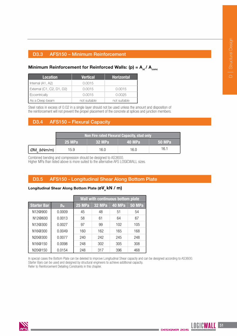
D3.3 AFS150 – Minimum Reinforcement
Location Vertical HorizontalInternal (A1, A2) 0.0015
External (C1, C2, D1, D2) 0.0015 0.0015
Eccentrically 0.0015 0.0025
As a Deep beam not suitable not suitable
D3.4 AFS150 – Flexural Capacity
Non Fire rated Flexural Capacity, stud only
25 MPa 32 MPa 40 MPa 50 MPa
ØMu (kNm/m) 15.9 16.0 16.0 16.1
Minimum Reinforcement for Reinforced Walls: (p) = Ast / Aconc
D3.5 AFS150 - Longitudinal Shear Along Bottom Plate
Wall with continuous bottom plate
Starter Bar pw 25 MPa 32 MPa 40 MPa 50 MPaN12@900 0.0009 45 48 51 54
N12@600 0.0013 58 61 64 67
N12@300 0.0027 97 99 102 105
N16@300 0.0049 160 162 165 168
N20@300 0.0077 240 242 245 248
N16@150 0.0098 248 302 305 308
N20@150 0.0154 248 317 396 468
In special cases the Bottom Plate can be deleted to improve Longitudinal Shear capacity and can be designed according to AS3600.Starter Bars can be used and designed by structural engineers to achieve additional capacity. Refer to Reinforcement Detailing Constraints in this chapter.
Longitudinal Shear Along Bottom Plate (øVu kN / m)
Combined bending and compression should be designed to AS3600.Higher MPa than listed above is more suited to the alternative AFS LOGICWALL sizes.
Steel ratios in excess of 0.02 in a single layer should not be used unless the amount and disposition of the reinforcement will not prevent the proper placement of the concrete at splices and junction members.

D
S
truct
ural
Des
ign
52DESIGNER 2015
52DESIGNER 2012 WALLING SOLUTIONS
D
S
truc
tura
l Des
ign
D3.6 AFS150 – Standard Lintels
1N12 Top & Btm, Depth mm, 'D' 1N16 Top & Btm, Depth mm, 'D'
Span (mm) 300 450 600 900 1200 300 450 600 900 1200
3900 4.5 7.3 10.2 15.9 21.7 7.8 13.0 18.2 28.6 39.0
3600 5.2 8.6 12.0 18.7 25.4 9.1 15.3 21.4 33.6 45.8
3300 6.2 10.2 14.2 22.2 30.2 10.9 18.2 25.4 40.0 54.5
3000 7.6 12.4 17.2 26.9 36.6 13.2 22.0 30.8 48.4 66.0
2700 9.3 15.3 21.3 33.2 45.2 16.2 27.1 38.0 59.7 81.4
2400 11.8 19.4 26.9 42.1 57.2 20.6 34.3 48.1 75.6 93.6
2100 15.4 25.3 35.2 54.9 74.7 26.9 44.8 62.8 92.8 107.0
1800 21.0 34.4 47.9 74.8 98.3 36.6 61.0 85.5 108.3 124.8
1500 30.2 49.6 69.0 98.2 118.0 52.6 87.8 110.2 130.0 149.8
1200 47.2 77.5 98.0 122.8 147.5 82.3 125.3 137.7 162.5 187.2
900 84.0 114.2 130.7 163.7 196.7 146.2 167.1 183.6 216.6 249.6
ØMu(kNm/m) 6.2 10.1 14.1 22.0 29.9 10.8 18.0 25.2 39.6 54.0
f.c=25 MPa, N12 Top and Bottom, 50 cover. f.c=25 MPa, N16 Top and Bottom, 50 cover.
ELEVATION
SECTION
* Additional reinforcement and ligatures can be used in lintels where additional capacity is required or where lintel is designed as a ‘T’ beam.
Capacity of lintels with vertical studs - UDL (w* kN/m)
ELEVATION
Opening
450
D
N12 or N16 Top & Bottom
SECTION
N12 or N16 Top & Bottom (minimum)

D
S
truct
ural
Des
ign
53DESIGNER 2015
53WALLING SOLUTIONS DESIGNER 2012
D
S
truc
tura
l Des
ign
H.we max N* max FRL
Type
tw
mm mm kN/m (Adeq/Integ/Insul.)AFS150 136 3000 200 240/240/180
* FRL’s determined by CSIRO Fire Test Number FS3637/2585.
* Refer to chapter L – ‘Certification’ to view CSIRO Test Certificate.
FRL by AS 3600Where design is outside the limits given in the above table FRL is to be detemined in accordance with AS 3600.
tw
mm Wall exposed on Wall exposed on
Type mm One side Two sides One side Two sides
AFS150 136 90/90/120 60/60/120 60/60/120 30/30/120
D3.7 AFS150 – FRL
1N12 Top & Btm, Depth mm 1N16 Top & Btm, Depth mm
Span (mm) 300 450 600 900 1200 300 450 600 900 1200
3900 4.5 7.3 10.2 15.9 21.7 7.8 13.0 18.2 28.6 39.0
3600 5.2 8.6 12.0 18.7 25.4 9.1 15.3 21.4 33.6 45.8
3300 6.2 10.2 14.2 22.2 30.2 10.9 18.2 25.4 40.0 54.5
3000 7.6 12.4 17.2 26.9 36.6 13.2 22.0 30.8 48.4 66.0
2700 9.3 15.3 21.3 33.2 45.2 16.2 27.1 38.0 59.7 81.4
2400 11.8 19.4 26.9 42.1 57.2 20.6 34.3 48.1 75.6 93.6
2100 15.4 25.3 35.2 54.9 74.7 26.9 44.8 62.8 92.8 107.0
1800 21.0 34.4 47.9 74.8 98.3 36.6 61.0 85.5 108.3 124.8
1500 30.2 49.6 69.0 98.2 118.0 52.6 87.8 110.2 130.0 149.8
1200 47.2 77.5 98.0 122.8 147.5 82.3 125.3 137.7 162.5 187.2
900 84.0 114.2 130.7 163.7 196.7 146.2 167.1 183.6 216.6 249.6
ØMu(kNm/m) 6.2 10.1 14.1 22.0 29.9 10.8 18.0 25.2 39.6 54.0
f.c=25 MPa, N12 Top and Bottom, 50 cover. f.c=25 MPa, N12 Top and Bottom, 50 cover.
SECTION
N*ƒ
Ø Nu
= 0.35N*
ƒ = 0.7Ø Nu

D
S
truct
ural
Des
ign
54DESIGNER 2015
54DESIGNER 2012 WALLING SOLUTIONS
D
S
truc
tura
l Des
ign
AFS 162
162mm150mm
100mm
6mm
6mm
25mm50mm30mm
170mm30mm
200mm200mm
25mm
D4 AFS162 AFS LOGICWALL®
D4.1 AFS162 - Stud Spacing & Profile
D4.2 AFS162 – Axial Capacity
AFS162 tw Ac %Stud Spacing 146 mm 150 47.2%
s Axial Capacity (øNu kN/m)
Wall Hgt (Hwu) Continuous Floor e=0.05xtw Dis-Continuous Floor e=0.167*tw
k=0.75 k=1.0 f’c=25 MPa f’c=32 MPa f’c=40 MPa f’c=50 MPa f’c=25 MPa f’c=32 MPa f’c=40 MPa f’c=50 MPa
6000 4500 297 380 475 594 108 138 173 216
5000 3750 594 760 950 1,188 405 518 648 810
4500 3375 722 924 1,156 1,445 533 683 853 1,067
4200 3150 793 1,015 1,268 1,585 604 773 966 1,207
3900 2925 358 1,099 1,373 1,717 669 857 1,071 1,339
3600 2700 919 1,176 1,471 1,838 730 935 1,168 1,460
3300 2475 975 1,248 1,560 1,950 786 1,006 1,258 1,572
3000 2250 1,026 1,313 1,642 2,052 837 1,071 1,339 1,674
2700 2025 1,072 1,372 1,715 2,144 883 1,130 1,413 1,766
2400 1800 1,113 1,425 1,782 2,227 924 1,183 1,479 1,849
2100 1575 1,150 1,472 1,840 2,300 961 1,230 1,537 1,922
1800 1350 1,182 1,512 1,890 2,363 993 1,270 1,588 1,985
wuH k = 0.75 we = 0.167 twe = 0.05 t H
wu k = 1.00 e = 0.167 twe = 0.05 t w
Axial capacity determined in accordance AS3600-2009 Cl.11.5.1 øNu=ø(t
w-1.2e - 2e
a) 0.6ƒ'
c k to be determined in accordance with AS3600-2009 Cl.11.4Eccentricity e to be determined in accordance AS3600-2009 Cl.11.5.2
D
S
truct
ural
Des
ign
55DESIGNER 2015
55WALLING SOLUTIONS DESIGNER 2012
D
S
truc
tura
l Des
ign
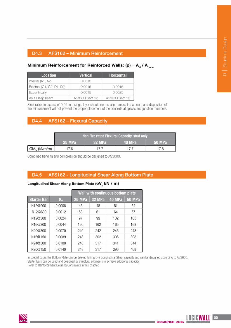
D4.4 AFS162 – Flexural Capacity
Non Fire rated Flexural Capacity, stud only
25 MPa 32 MPa 40 MPa 50 MPaØMU (kNm/m) 17.6 17.7 17.7 17.8
D4.3 AFS162 – Minimum Reinforcement
Location Vertical HorizontalInternal (A1, A2) 0.0015
External (C1, C2, D1, D2) 0.0015 0.0015
Eccentrically 0.0015 0.0025
As a Deep beam AS3600 Sect 12 AS3600 Sect 12
D4.5 AFS162 - Longitudinal Shear Along Bottom Plate
Wall with continuous bottom plate
Starter Bar pw 25 MPa 32 MPa 40 MPa 50 MPaN12@900 0.0008 45 48 51 54
N12@600 0.0012 58 61 64 67
N12@300 0.0024 97 99 102 105
N16@300 0.0044 160 162 165 168
N20@300 0.0070 240 242 245 248
N16@150 0.0089 248 302 305 308
N24@300 0.0100 248 317 341 344
N20@150 0.0140 248 317 396 468
In special cases the Bottom Plate can be deleted to improve Longitudinal Shear capacity and can be designed according to AS3600.Starter Bars can be used and designed by structural engineers to achieve additional capacity. Refer to Reinforcement Detailing Constraints in this chapter.
Minimum Reinforcement for Reinforced Walls: (p) = Ast / Aconc
Longitudinal Shear Along Bottom Plate (øVu kN / m)
Combined bending and compression should be designed to AS3600.
Steel ratios in excess of 0.02 in a single layer should not be used unless the amount and disposition of the reinforcement will not prevent the proper placement of the concrete at splices and junction members.
D
S
truct
ural
Des
ign
56DESIGNER 2015
56DESIGNER 2012 WALLING SOLUTIONS
D
S
truc
tura
l Des
ign
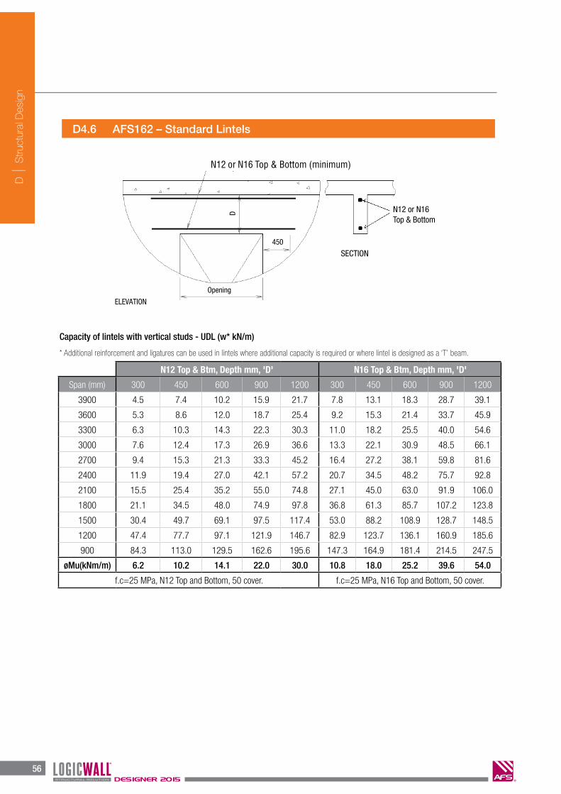
D4.6 AFS162 – Standard Lintels
N12 Top & Btm, Depth mm, 'D' N16 Top & Btm, Depth mm, 'D'
Span (mm) 300 450 600 900 1200 300 450 600 900 1200
3900 4.5 7.4 10.2 15.9 21.7 7.8 13.1 18.3 28.7 39.1
3600 5.3 8.6 12.0 18.7 25.4 9.2 15.3 21.4 33.7 45.9
3300 6.3 10.3 14.3 22.3 30.3 11.0 18.2 25.5 40.0 54.6
3000 7.6 12.4 17.3 26.9 36.6 13.3 22.1 30.9 48.5 66.1
2700 9.4 15.3 21.3 33.3 45.2 16.4 27.2 38.1 59.8 81.6
2400 11.9 19.4 27.0 42.1 57.2 20.7 34.5 48.2 75.7 92.8
2100 15.5 25.4 35.2 55.0 74.8 27.1 45.0 63.0 91.9 106.0
1800 21.1 34.5 48.0 74.9 97.8 36.8 61.3 85.7 107.2 123.8
1500 30.4 49.7 69.1 97.5 117.4 53.0 88.2 108.9 128.7 148.5
1200 47.4 77.7 97.1 121.9 146.7 82.9 123.7 136.1 160.9 185.6
900 84.3 113.0 129.5 162.6 195.6 147.3 164.9 181.4 214.5 247.5
øMu(kNm/m) 6.2 10.2 14.1 22.0 30.0 10.8 18.0 25.2 39.6 54.0
f.c=25 MPa, N12 Top and Bottom, 50 cover. f.c=25 MPa, N16 Top and Bottom, 50 cover.
ELEVATION
Opening
450
N12 or N16 Top & Bottom
SECTION
D
N12 or N16 Top & Bottom (minimum)
* Additional reinforcement and ligatures can be used in lintels where additional capacity is required or where lintel is designed as a ‘T’ beam.
Capacity of lintels with vertical studs - UDL (w* kN/m)
D
S
truct
ural
Des
ign
57DESIGNER 2015
57WALLING SOLUTIONS DESIGNER 2012
D
S
truc
tura
l Des
ign
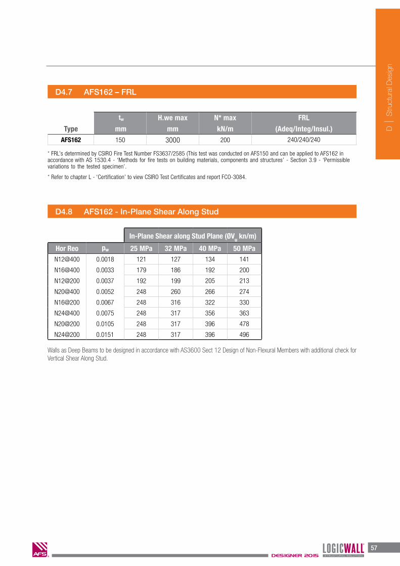
D4.7 AFS162 – FRL
FRL by AS 3600Where design is outside the limits given in the above table FRL is to be detemined in accordance with AS 3600.
tw
mm Wall exposed on Wall exposed on
Type mm One side Two sides One side Two sides
AFS162 150 120/120/180 90/90/180 90/90/180 60/60/180
D4.8 AFS162 - In-Plane Shear Along Stud
In-Plane Shear along Stud Plane (ØVu kn/m)
Hor Reo pw 25 MPa 32 MPa 40 MPa 50 MPaN12@400 0.0018 121 127 134 141
N16@400 0.0033 179 186 192 200
N12@200 0.0037 192 199 205 213
N20@400 0.0052 248 260 266 274
N16@200 0.0067 248 316 322 330
N24@400 0.0075 248 317 356 363
N20@200 0.0105 248 317 396 478
N24@200 0.0151 248 317 396 496
Walls as Deep Beams to be designed in accordance with AS3600 Sect 12 Design of Non-Flexural Members with additional check for Vertical Shear Along Stud.
H.we max N* max FRL
Type
tw
mm mm kN/m (Adeq/Integ/Insul.)AFS162 150 3000 200 240/240/240
* FRL’s determined by CSIRO Fire Test Number FS3637/2585 (This test was conducted on AFS150 and can be applied to AFS162 in accordance with AS 1530.4 - ‘Methods for fire tests on building materials, components and structures’ - Section 3.9 - ‘Permissible variations to the tested specimen’.
* Refer to chapter L - ‘Certification’ to view CSIRO Test Certificates and report FCO-3084.
N*ƒ
Ø Nu
= 0.35N*
ƒ = 0.7Ø Nu
57WALLING SOLUTIONS DESIGNER 2012
D
S
truc
tura
l Des
ign
D4.7 AFS162 – FRL
FRL by AS 3600Where design is outside the limits given in the above table FRL is to be detemined in accordance with AS 3600.
tw
mm Wall exposed on Wall exposed on
Type mm One side Two sides One side Two sides
AFS162 150 120/120/180 90/90/180 90/90/180 60/60/180
D4.8 AFS162 - In-Plane Shear Along Stud
In-Plane Shear along Stud Plane (ØVu kn/m)
Hor Reo pw 25 MPa 32 MPa 40 MPa 50 MPaN12@400 0.0018 121 127 134 141
N16@400 0.0033 179 186 192 200
N12@200 0.0037 192 199 205 213
N20@400 0.0052 248 260 266 274
N16@200 0.0067 248 316 322 330
N24@400 0.0075 248 317 356 363
N20@200 0.0105 248 317 396 478
N24@200 0.0151 248 317 396 496
Walls as Deep Beams to be designed in accordance with AS3600 Sect 12 Design of Non-Flexural Members with additional check for Vertical Shear Along Stud.
H.we max N* max FRL
Type
tw
mm mm kN/m (Adeq/Integ/Insul.)AFS162 150 3000 200 240/240/240
* FRL’s determined by CSIRO Fire Test Number FS3637/2585 (This test was conducted on AFS150 and can be applied to AFS162 in accordance with AS 1530.4 - ‘Methods for fire tests on building materials, components and structures’ - Section 3.9 - ‘Permissible variations to the tested specimen’.
* Refer to chapter L - ‘Certification’ to view CSIRO Test Certificates and report FCO-3084.
N*ƒ
Ø Nu
= 0.35N*
ƒ = 0.7Ø Nu

D
S
truct
ural
Des
ign
58DESIGNER 2015
58DESIGNER 2012 WALLING SOLUTIONS
D
S
truc
tura
l Des
ign
AFS 200
D5 AFS200 LOGICWALL® – Design Load Tables
D5.1 AFS200 – Stud Spacing & Profile
D5.2 AFS200 – Axial Capacity
AFS200 tw Ac %Stud Spacing 146 mm 188 50.0%
s Axial Capacity (øNu kN/m)
Wall Hgt (Hwu) Continuous Floor e=0.05xtw Dis-Continuous Floor e=0.167*tw
k=0.75 k=1.0f’c=25 MPa
f’c=32 MPa
f’c=40 MPa
f’c=50 MPa
f’c=65 MPa
f’c=25 MPa
f’c=32 MPa
f’c=40 MPa
f’c=50 MPa
f’c=65 MPa
6000 4500 815 1,043 1,304 1,630 2,119 578 740 925 1,156 1,503
5000 3750 1,052 1,346 1,683 2,104 2,735 815 1,043 1,304 1,630 2,119
4500 3375 1,154 1,477 1,847 2,308 3,001 917 1,174 1,468 1,835 2,385
4200 3150 1,210 1,549 1,937 2,421 3,147 974 1,246 1,558 1,947 2,531
3900 2925 1,263 1,616 2,021 2,526 3,283 1,026 1,313 1,642 2,052 2,667
3600 2700 1,311 1,678 2,098 2,623 3,409 1,074 1,375 1,719 2,149 2,793
3300 2475 1,356 1,736 2,169 2,712 3,525 1,119 1,432 1,790 2,238 2,909
3000 2250 1,397 1,788 2,235 2,793 3,631 1,160 1,484 1,856 2,319 3,015
2700 2025 1,433 1,835 2,293 2,867 3,727 1,197 1,532 1,914 2,393 3,111
2400 1800 1,466 1,877 2,346 2,933 3,813 1,230 1,574 1,967 2,459 3,197
2100 1575 1,495 1,914 2,393 2,991 3,888 1,259 1,611 2,014 2,517 3,272
1800 1350 1,521 1,946 2,433 3,041 3,954 1,284 1,643 2,054 2,568 3,338
wuH k = 0.75 we = 0.167 twe = 0.05 t H
wu k = 1.00 e = 0.167 twe = 0.05 t w
Axial capacity determined in accordance AS3600-2009 Cl.11.5.1 øNu=ø(t
w-1.2e - 2e
a) 0.6ƒ'
c k to be determined in accordance with AS3600-2009 Cl.11.4Eccentricity e to be determined in accordance AS3600-2009 Cl.11.5.2
200m
m
188m
m
134m
m
6mm
6mm33
mm
50m
m166mm200mm
33m
m
200mm 200mm 200mm

D
S
truct
ural
Des
ign
59DESIGNER 2015
59WALLING SOLUTIONS DESIGNER 2012
D
S
truc
tura
l Des
ign
D5.3 AFS200 – Minimum Reinforcement
D5.4 AFS200 – Flexural Capacity
s Non Fire rated Flexural Capacity, stud only
25 MPa 32 MPa 40 MPa 50 MPa 65 MPaØMU (kNm/m) 22.2 22.3 22.3 22.4 22.4
Combined bending and compression should be designed to AS3600
D5.5 AFS200 – Longitudinal Shear Along Bottom Plate
Wall with continuous bottom plate
Starter Bar p.w. 25 MPa 32 MPa 40 MPa 50 MPa 65 MPaN12@900 0.0008 45 48 51 54 58
N12@600 0.0010 58 61 64 67 70
N12@300 0.0020 97 99 102 105 109
N16@300 0.0035 160 162 165 168 172
N20@300 0.0056 240 242 245 248 252
N16@150 0.0071 248 302 305 308 312
N24@300 0.0080 248 318 342 344 348
N28@300 0.0108 248 318 397 455 459
N20@150 0.0111 248 318 397 468 472
N24@150 0.0160 248 318 397 496 496
In special cases the Bottom Plate can be deleted to improve Longitudinal Shear capacity and can be designed according to AS3600.Starter Bars can be used and designed by structural engineers to achieve additional capacity. Refer to Reinforcement Detailing Constraints in this chapter.
Minimum Reinforcement for Reinforced Walls: (p) = Ast / Aconc
Longitudinal Shear Along Bottom Plate (øVu kN / m)
Steel ratios in excess of 0.02 in a single layer should not be used unless the amount and disposition of the reinforcement will not prevent the proper placement of the concrete at splices and at junction members.
s Axial Capacity (øNu kN/M)
Wall Hgt (Hwu) Continuous Floor e=0.05xtw Dis-Continuous Floor e=0.167*tw
k=0.75 k=1.0f’c=25 MPa
f’c=32 MPa
f’c=40 MPa
f’c=50 MPa
f’c=65 MPa
f’c=25 MPa
f’c=32 MPa
f’c=40 MPa
f’c=50 MPa
f’c=65 MPa
6000 4500 815 1,043 1,304 1,630 2,119 578 740 925 1,156 1,503
5000 3750 1,052 1,346 1,683 2,104 2,735 815 1,043 1,304 1,630 2,119
4500 3375 1,154 1,477 1,847 2,308 3,001 917 1,174 1,468 1,835 2,385
4200 3150 1,210 1,549 1,937 2,421 3,147 974 1,246 1,558 1,947 2,531
3900 2925 1,263 1,616 2,021 2,526 3,283 1,026 1,313 1,642 2,052 2,667
3600 2700 1,311 1,678 2,098 2,623 3,409 1,074 1,375 1,719 2,149 2,793
3300 2475 1,356 1,736 2,169 2,712 3,525 1,119 1,432 1,790 2,238 2,909
3000 2250 1,397 1,788 2,235 2,793 3,631 1,160 1,484 1,856 2,319 3,015
2700 2025 1,433 1,835 2,293 2,867 3,727 1,197 1,532 1,914 2,393 3,111
2400 1800 1,466 1,877 2,346 2,933 3,813 1,230 1,574 1,967 2,459 3,197
2100 1575 1,495 1,914 2,393 2,991 3,888 1,259 1,611 2,014 2,517 3,272
1800 1350 1,521 1,946 2,433 3,041 3,954 1,284 1,643 2,054 2,568 3,338
Location Vertical HorizontalInternal (A1, A2) 0.0015
External (C1, C2, D1, D2) 0.0015 0.0015
Eccentrically 0.0015 0.0025
As a Deep beam AS3600 Sect 12 AS3600 Sect 12

D
S
truct
ural
Des
ign
60DESIGNER 2015
60DESIGNER 2012 WALLING SOLUTIONS
D
S
truc
tura
l Des
ign
Opening
450
N12 or N16 Top & Bottom
SECTIOND
D5.6 AFS200 – Standard Lintels
1N12 Top & Btm, Depth (mm) 1N16 Top & Btm, Depth (mm)
Span (mm) 300 450 600 900 1200 300 450 600 900 1200
3900 6.1 10.9 15.7 25.2 34.8 10.8 19.5 28.2 45.5 47.2
3600 7.2 12.8 18.4 29.6 40.8 12.7 22.9 33.1 51.2 51.2
3300 8.6 15.2 21.9 35.2 48.6 15.1 27.3 39.4 55.8 55.8
3000 10.4 18.4 26.5 42.6 58.8 18.3 33.0 47.6 61.4 61.4
2700 12.8 22.8 32.7 52.6 68.2 22.6 40.7 58.8 68.2 68.2
2400 16.2 28.8 41.4 63.5 76.8 28.6 51.5 68.4 76.8 76.8
2100 21.2 37.6 54.1 72.6 87.7 37.4 67.3 78.2 87.7 87.7
1800 28.8 51.2 65.0 84.7 102.4 50.9 81.4 91.2 102.4 102.4
1500 41.5 66.1 78.0 101.7 122.8 73.2 97.6 109.5 122.8 122.8
1200 64.9 82.7 97.5 127.1 153.5 107.2 122.0 136.9 153.5 153.5
900 90.5 110.2 130.0 169.4 204.7 143.0 162.7 182.5 204.7 204.7
ELEVATION
N12 or N16 Top & Bottom (minimum)
Capacity of standard lintels with vertical studs - UDL (w* kN/m)
Capacity can be increased with additional reinforcement or as composite L beam with slab.
deff 200 350 500 800 1100 200 350 500 800 1100
Limited by shear
25 MPa 188 200 1 50% 0.55 N20 100% 188 0.75 0.25
f'c tw spunch Nlayers Ac Web Max.Hor Align. twshear µ kco
AFS200
Type

D
S
truct
ural
Des
ign
61DESIGNER 2015
61WALLING SOLUTIONS DESIGNER 2012
D
S
truc
tura
l Des
ign
D5.7 AFS200 – FRL
D5.8 AFS200 - In-Plane Shear Along Stud
Bars (H) p 25 MPa 32 MPa 40 MPa 50 MPa 65 MPaN12@800 0.0008
N12@600 0.0010
N12@400 0.0015
N12@300 0.0020
N16@400 0.0027 191.1 198.9 206.8 215.7 227.4
N12@200 0.0030 207.5 215.3 223.2 232.1 243.8
N16@300 0.0036 235.1 242.9 250.8 259.6 271.4
N20@400 0.0042 265.3 273.1 281.0 289.8 301.6
H.we max N* max FRL
Type
tw
mm mm kN/m (Adeq/Integ/Insul.)AFS200 188 3000 200 240/240/240
* FRL’s determined by CSIRO Fire Test Number FS3637/2585 This test was conducted on AFS150 and can be applied to AFS200 inaccordance with AS 1530.4 - ‘Methods for fire tests on building materials, components and structures’ - Section 3.9 - ‘Permissiblevariations to the tested specimen’.
* Refer to chapter L – ‘Certification’ to view CSIRO Test Certificates and report FCO-3004.
188 200 1 50% 100% N20 0.0025 350 188 0.75 0.25
tw spunch Nlayers Ac Align. Max.Hor Min reo Max Spacing twshear µ kco
AFS200
Type
N16@200 0.0053 323.0 330.8 338.7 347.6 359.3
N20@300 0.0056 329.0 341.7 349.7 358.5 370.2
N20@200 0.0084 421.1 487.0 495.9 507.6

D
S
truct
ural
Des
ign
62DESIGNER 2015
62DESIGNER 2012 WALLING SOLUTIONS
D
S
truc
tura
l Des
ign
AFS 200D
D6 AFS200D AFS LOGICWALL® – Design Load Tables
D6.1 AFS200D – Stud Spacing & Profile
D6.2 AFS200D – Axial Capacity
AFS200D tw Ac %Stud Spacing 146 mm 188 50%
s Axial Capacity (øNu kN/m)
Wall Hgt (Hwu) Continuous Floor e=0.05xtw Dis-Continuous Floor e=0.167*tw
k=0.75 k=1,0f’c=25 MPa
f’c=32 MPa
f’c=40 MPa
f’c=50 MPa
f’c=65 MPa
f’c=25 MPa
f’c=32 MPa
f’c=40 MPa
f’c=50 MPa
f’c=65 MPa
6000 4500 815 1,043 1,304 1,630 2,119 578 740 925 1,156 1,503
5000 3750 1,052 1,346 1,683 2,104 2,735 815 1,043 1,304 1,630 2,119
4500 3375 1,154 1,477 1,847 2,308 3,001 917 1,174 1,468 1,835 2,385
4200 3150 1,210 1,549 1,937 2,421 3,147 974 1,246 1,558 1,947 2,531
3900 2925 1,263 1,616 2,021 2,526 3,283 1,026 1,313 1,642 2,052 2,667
3600 2700 1,311 1,678 2,098 2,623 3,409 1,074 1,375 1,719 2,149 2,793
3300 2475 1,356 1,736 2,169 2,712 3,525 1,119 1,432 1,790 2,238 2,909
3000 2250 1,397 1,788 2,235 2,793 3,631 1,160 1,484 1,856 2,319 3,015
2700 2025 1,433 1,835 2,293 2,867 3,727 1,197 1,532 1,914 2,393 3,111
2400 1800 1,466 1,877 2,346 2,933 3,813 1,230 1,574 1,967 2,459 3,197
2100 1575 1,495 1,914 2,393 2,991 3,888 1,259 1,611 2,014 2,517 3,272
1800 1350 1,521 1,946 2,433 3,041 3,954 1,284 1,643 2,054 2,568 3,338
wuH k = 0.75 we = 0.167 twe = 0.05 t H
wu k = 1.00 e = 0.167 twe = 0.05 t w
Axial capacity determined in accordance AS3600-2009 Cl.11.5.1 øNu=ø(t
w-1.2e - 2e
a) 0.6ƒ'
c k to be determined in accordance with AS3600-2009 Cl.11.4Eccentricity e to be determined in accordance AS3600-2009 Cl.11.5.2
200m
m
188m
m
134m
m
6mm
6mm33
mm
50m
m166mm200mm
33m
m
200mm 200mm 200mm

D
S
truct
ural
Des
ign
63DESIGNER 2015
63WALLING SOLUTIONS DESIGNER 2012
D
S
truc
tura
l Des
ign
D6.3 AFS200D – Minimum Reinforcement
Location Vertical HorizontalInternal (A1, A2) 0.0015
External (C1, C2, D1, D2) 0.0015 0.0015
Eccentrically 0.0015 0.0025
As a Deep beam AS3600 Sect 12 AS3600 Sect 12
D6.4 AFS200D – Flexural Capacity
Combined bending and compression should be designed to AS3600
s Non Fire rated Flexural Capacity, stud only
25 MPa 32 MPa 40 MPa 50 MPa 65 MPaØMU (kNm/m) 22.8 22.3 22.3 22.4 22.4
D6.5 AFS200D – Longitudinal Shear Along Bottom Plate
Wall with continuous bottom plate
Starter Bar p.w. 25 MPa 32 MPa 40 MPa 50 MPa 65 MPaN12@900 0.0007 41 44 46 48 51
N12@600 0.0010 54 56 58 61 64
N12@300 0.0020 93 95 97 99 102
N16@300 0.0035 156 158 160 162 165
N20@300 0.0056 197 238 240 242 245
N16@150 0.0071 197 253 300 302 305
N24@300 0.0080 197 253 316 339 342
N28@300 0.0108 197 253 316 395 395
N20@150 0.0111 197 253 316 395 395
N24@150 0.0160 197 253 316 395 395
In special cases the Bottom Plate can be deleted to improve Longitudinal Shear capacity and can be designed according to AS3600.Starter Bars can be used and designed by structural engineers to achieve additional capacity. Refer to Reinforcement Detailing Constraints in this chapter.
Minimum Reinforcement for Reinforced Walls: (p) = Ast / Aconc
Longitudinal Shear Along Bottom Plate (øVu kN / m)
Steel ratios in excess of 0.02 in a single layer should not be used unless the amount and disposition of the reinforcement will not prevent the proper placement of the concrete at splices and at junction members.
s Axial Capacity (øNu kN/M)
Wall Hgt (Hwu) Continuous Floor e=0.05xtw Dis-Continuous Floor e=0.167*tw
k=0.75 k=1,0f’c=25 MPa
f’c=32 MPa
f’c=40 MPa
f’c=50 MPa
f’c=65 MPa
f’c=25 MPa
f’c=32 MPa
f’c=40 MPa
f’c=50 MPa
f’c=65 MPa
6000 4500 815 1,043 1,304 1,630 2,119 578 740 925 1,156 1,503
5000 3750 1,052 1,346 1,683 2,104 2,735 815 1,043 1,304 1,630 2,119
4500 3375 1,154 1,477 1,847 2,308 3,001 917 1,174 1,468 1,835 2,385
4200 3150 1,210 1,549 1,937 2,421 3,147 974 1,246 1,558 1,947 2,531
3900 2925 1,263 1,616 2,021 2,526 3,283 1,026 1,313 1,642 2,052 2,667
3600 2700 1,311 1,678 2,098 2,623 3,409 1,074 1,375 1,719 2,149 2,793
3300 2475 1,356 1,736 2,169 2,712 3,525 1,119 1,432 1,790 2,238 2,909
3000 2250 1,397 1,788 2,235 2,793 3,631 1,160 1,484 1,856 2,319 3,015
2700 2025 1,433 1,835 2,293 2,867 3,727 1,197 1,532 1,914 2,393 3,111
2400 1800 1,466 1,877 2,346 2,933 3,813 1,230 1,574 1,967 2,459 3,197
2100 1575 1,495 1,914 2,393 2,991 3,888 1,259 1,611 2,014 2,517 3,272
1800 1350 1,521 1,946 2,433 3,041 3,954 1,284 1,643 2,054 2,568 3,338

D
S
truct
ural
Des
ign
64DESIGNER 2015
64DESIGNER 2012 WALLING SOLUTIONS
D
S
truc
tura
l Des
ign
ELEVATIONOpening
450
2N12 or 2N16 Top & Bottom (minimum)
N12 or N16 Top & Bottom
SECTIOND
D6.6 AFS200D – Standard Lintels
2N12 Top & Btm, Depth (mm) 2N16 Top & Btm, Depth (mm)
Span (mm) 300 450 600 900 1200 300 450 600 900 1200
3900 8.8 14.5 20.2 31.7 43.1 15.0 25.4 35.9 56.7 73.8
3600 10.3 17.0 23.7 37.2 50.6 17.6 29.9 42.1 66.5 83.0
3300 12.3 20.3 28.3 44.3 60.3 21.0 35.5 50.1 79.2 87.3
3000 14.8 24.5 34.2 53.6 67.0 25.4 43.0 60.6 88.1 96.0
2700 18.3 30.3 42.2 65.7 74.4 31.4 53.1 74.8 97.9 106.6
2400 23.2 38.3 53.4 73.9 83.8 39.7 67.2 94.7 110.1 120.0
2100 30.3 50.0 69.8 84.4 95.7 51.8 84.6 112.8 125.8 137.1
1800 41.2 68.1 85.4 98.5 111.7 65.8 98.7 131.6 146.8 160.0
1500 59.4 94.5 102.4 118.2 134.0 79.0 118.4 157.9 176.2 192.0
1200 92.7 118.2 128.0 147.8 167.5 98.7 148.1 197.4 220.2 240.0
900 131.6 157.5 170.7 197.0 223.3 131.6 197.4 263.2 293.6 319.9
ØMu(kNm/m) 12.1 20.1 28.0 43.8 59.7 20.8 35.2 49.6 78.4 107.2
f.c=25 MPa, N12 Top & Bottom, 50 cover. f.c=25 MPa, N16 Top & Bottom, 50 cover.
* Additional reinforcement and ligatures can be used in lintels where additional capacity is required or where lintel is designed as a ‘T’ beam.
Lintels vertical studs - UDL (ØVu kN/m)
Capacity of Standard Lintels with Vertical Studs- UDL (w* kN/m)Capacity can be increased with additional reinforcement or as composite L beam with slab.
2N12 Top & Btm, Depth (mm) ‘D’ 2N16 Top & Btm, Depth (mm) ‘D’
D 300 450 600 900 1200 300 450 600 900 1200
deff 200 350 500 800 1100 200 350 500 800 1100
Span (mm)
3900 11.8 21.4 30.9 47.2 47.2 20.2 37.5 47.2 47.2 47.2
3600 13.9 25.1 36.3 51.2 51.2 23.7 44.1 51.2 51.2 51.2
3300 16.5 29.9 43.2 55.8 55.8 28.2 52.4 55.8 55.8 55.8
3000 20.0 36.1 52.3 61.4 61.4 34.1 61.4 61.4 61.4 61.4
2700 24.7 44.6 64.5 68.2 68.2 42.1 68.2 68.2 68.2 68.2
2400 31.3 56.5 72.8 76.8 76.8 53.3 76.8 76.8 76.8 76.8
2100 40.8 73.7 83.2 87.7 87.7 69.6 87.7 87.7 87.7 87.7
1800 55.6 87.2 97.1 102.4 102.4 94.8 102.4 102.4 102.4 102.4
1500 80.0 104.6 116.5 122.8 122.8 122.8 122.8 122.8 122.8 122.8
1200 116.0 130.8 145.6 153.5 153.5 153.5 153.5 153.5 153.5 153.5
900 154.7 174.4 194.1 204.7 204.7 204.7 204.7 204.7 204.7 204.7
limited by shear
f’c tw spunch Nlayers Ac Web Max.Hor Align. twshear μ kco
25 MPa 188 200 2 50% 0.55 N16 100% 188 0.75 0.25

D
S
truct
ural
Des
ign
65DESIGNER 2015
65WALLING SOLUTIONS DESIGNER 2012
D
S
truc
tura
l Des
ign
FRL by AS 3600Where design is outside the limits given in the above table FRL is to be detemined in accordance with AS 3600.
tw
mm Wall exposed on Wall exposed on
Type mm One side Two sides One side Two sides
AFS200D 188 180/180/240 120/120/240 120/120/240 90/90/240
D6.7 AFS200D – FRL
D6.8 AFS200D - In-Plane Shear Along Stud
In-Plane Shear along Stud Plane (ØVu kn/m)
Hor Reo pw 25 MPa 32 MPa 40 MPa 50 MPa 65 MPaN12@400EF 0.0029 172 177 183 189 196
N16@400EF 0.0053 197 253 291 297 305
N12@200EF 0.0059 197 253 316 321 329
N20@400EF 0.0084 197 253 316 395 395
N16@200EF 0.0106 197 253 316 395 395
N24@200EF 0.0120 197 253 316 395 395
N20@200EF 0.0167 197 253 316 395 395
N24@200EF 0.0240 197 253 316 395 395
N28@200EF 0.0324 197 253 316 395 395
Walls as Deep Beams to be designed in accordance with AS3600 Sect 12 Design of Non-Flexural Members with additional check for Vertical Shear Along Stud.
SECTION
N* max FRL
Type
tw
mm
Hwe max
mm kN/m (Adeq/Integ/Insul.)AFS200D 188 3000 200 240/240/240
* FRL’s determined by CSIRO Fire Test Number FS3637/2585 This test was conducted on AFS150 and can be applied to AFS200D inaccordance with AS 1530.4 - ‘Methods for fire tests on building materials, components and structures’ - Section 3.9 - ‘Permissiblevariations to the tested specimen’.
* Refer to chapter L – ‘Certification’ to view CSIRO Test Certificates and report FCO-3084.
N*ƒ
Ø Nu
= 0.35N*
ƒ = 0.7Ø Nu
Bars (H) p 25 MPa 32 MPa 40 MPa 50 MPa 65 MPa
2N12@800 0.0015
2N12@600 0.0020
2N12@400 0.0030 207.5 215.3 223.2 232.1 243.8
2N12@300 0.0040 257.0 264.7 272.1 281.5 293.2
2N16@400 0.0053 323.0 330.8 338.7 347.6 359.3
2N12@200 0.0060 329.0 363.6 371.5 380.4 392.1
2N16@300 0.0071 418.7 426.7 435.5 447.2
2N20@400
2N16@200 0.0107 421.1 526.4 611.4 623.1
tw spunch Nlayers Ac Align Max.Hor Min Reo Max Spacing twshear μ kco
188 200 2 50% 100% N16 0.0025 350 188 0.75 0.25

D
S
truct
ural
Des
ign
66DESIGNER 2015
66DESIGNER 2012 WALLING SOLUTIONS
D
S
truc
tura
l Des
ign
211m
m
262m
m
AFS 262D
250m
m6m
m6m
m
19.5
mm
50m
m
160mm200mm200mm
19.5
mm
D7 AFS262D AFS LOGICWALL® – Design Load Tables
D7.1 AFS262D – Stud Spacing & Profile
D7.2 AFS262D – Axial Capacity
AFS262D tw Ac %Stud Spacing 146 mm 250 50%
s Axial Capacity (øNu kN/m)
Wall Hgt (Hwu) Continuous Floor e=0.05xtw Dis-Continuous Floor e=0.167*tw
k=0.75 k=1,0f’c=25 MPa
f’c=32 MPa
f’c=40 MPa
f’c=50 MPa
f’c=65 MPa
f’c=25 MPa
f’c=32 MPa
f’c=40 MPa
f’c=50 MPa
f’c=65 MPa
6000 4500 1,532 1,961 2,451 3,064 3,983 1,217 1,558 1,947 2,434 3,164
5000 3750 1,710 2,189 2,736 3,420 4,446 1,395 1,786 2,232 2,790 3,627
4500 3375 1,787 2,287 2,859 3,574 4,646 1,472 1,884 2,355 2,944 3,827
4200 3150 1,829 2,341 2,927 3,658 4,756 1,514 1,938 2,423 3,028 3,937
3900 2925 1,869 2,392 2,990 3,737 4,858 1,554 1,989 2,486 3,107 4,039
3600 2700 1,905 2,438 3,348 3,800 4,953 1,590 2,035 2,544 3,180 4,134
3300 2475 1,939 2,481 3,002 3,877 5,040 1,624 2,078 2,598 3,247 4,221
3000 2250 1,969 2,521 3,151 3,938 5,120 1,654 2,117 2,647 3,308 4,301
2700 2025 1,997 2,556 3,095 3,994 5,092 1,682 2,153 2,691 3,364 4,373
2400 1800 2,022 2,588 3,235 4,043 5,256 1,707 2,185 2,731 3,413 4,437
2100 1575 2,044 2,616 3,270 4,087 5,313 1,729 2,213 2,766 3,457 4,494
1800 1350 2,063 2,640 3,300 4,125 5,363 1,748 2,237 2,796 3,495 4,544
wuH k = 0.75 we = 0.167 twe = 0.05 t H
wu k = 1.00 e = 0.167 twe = 0.05 t w
Axial capacity determined in accordance AS3600-2009 Cl.11.5.1 øNu=ø(t
w-1.2e - 2e
a) 0.6ƒ'
c k to be determined in accordance with AS3600-2009 Cl.11.4Eccentricity e to be determined in accordance AS3600-2009 Cl.11.5.2

D
S
truct
ural
Des
ign
67DESIGNER 2015
67WALLING SOLUTIONS DESIGNER 2012
D
S
truc
tura
l Des
ign
D7.3 AFS262D – Minimum Reinforcement
Location Vertical HorizontalInternal (A1, A2) 0.0015
External (C1, C2, D1, D2) 0.0015 0.0015
Eccentrically 0.0015 0.0025
As a Deep beam AS3600 Sect 12 AS3600 Sect 12
D7.4 AFS262D – Flexural Capacity
D7.5 AFS262D – Longitudinal Shear Along Bottom Plate
Combined bending and compression should be designed to AS3600
s Non Fire rated Flexural Capacity, stud only
25 MPa 32 MPa 40 MPa 50 MPa 65 MPaØMu (kNm/m) 29.7 29.7 29.8 29.8 29.9
Wall with continuous bottom plate
Starter Bar pw 25 MPa 32 MPa 40 MPa 50 MPa 65 MPaN12@900 0.0005 61 65 70 75 82
N12@600 0.0007 74 78 83 88 95
N12@300 0.0015 112 117 121 126 133
N16@300 0.0027 175 180 184 189 196
N20@300 0.0042 255 259 264 269 276
N16@150 0.0053 315 320 324 329 336
N24@300 0.0060 351 356 361 366 373
N28@300 0.0081 438 467 471 476 483
N20@150 0.0084 438 479 484 489 496
N24@150 0.0121 438 560 677 682 689
N28@150 0.0163 438 560 700 875 875
In special cases the Bottom Plate can be deleted to improve Longitudinal Shear capacity and can be designed according to AS3600.Starter Bars can be used and designed by structural engineers to achieve additional capacity. Refer to Reinforcement Detailing Constraints in this chapter.
Minimum Reinforcement for Reinforced Walls: (p) = Ast / Aconc
Longitudinal Shear Along Bottom Plate (øVu kN / m)
Steel ratios in excess of 0.02 in a single layer should not be used unless the amount and disposition of the reinforcement will not prevent the proper placement of the concrete at splices and at junction members.

D
S
truct
ural
Des
ign
68DESIGNER 2015
68DESIGNER 2012 WALLING SOLUTIONS
D
S
truc
tura
l Des
ign
D7.6 AFS262D – Standard Lintels
2N12 Top & Btm, Depth mm 'D' 2N16 Top & Btm, Depth mm 'D'
Span (mm) 300 450 600 900 1200 300 450 600 900 1200
3900 8.9 14.6 20.4 31.8 43.3 15.5 25.9 36.3 57.1 78.0
3600 10.5 17.2 23.9 37.4 50.8 18.2 30.4 42.6 67.0 91.5
3300 12.5 20.5 28.5 44.5 60.5 21.6 36.2 50.7 79.8 108.9
3000 15.1 24.7 34.4 53.8 73.1 26.1 43.7 61.3 96.5 131.7
2700 18.6 30.5 42.5 66.4 90.3 32.3 54.0 75.7 119.2 155.6
2400 23.5 38.7 53.8 84.0 114.3 40.8 68.3 95.8 150.8 175.0
2100 30.7 50.5 70.3 109.8 149.3 53.4 89.3 125.2 175.0 200.0
1800 41.8 68.7 95.6 149.4 180.8 72.6 121.5 170.4 204.2 233.3
1500 60.3 99.0 137.7 182.0 217.0 104.6 175.0 210.0 245.0 280.0
1200 94.2 154.7 183.8 227.5 271.3 163.4 240.6 262.5 306.3 350.0
900 167.4 215.8 245.0 303.3 361.7 290.5 320.8 350.0 408.3 466.7
øMu(kNm/m) 12.3 20.2 28.2 44.0 59.8 21.4 35.8 50.2 79.0 107.8
f.c=25 MPa, N12 Top and Bottom, 50 cover. f.c=25 MPa, N16 Top and Bottom, 50 cover.
Additional reinforcement and ligatures can be used in lintels where additional capacity is required or where lintel is designed as a ‘T’ beam.
Capacity of lintels with vertical studs - UDL (w* kN/m)
ELEVATIONOpening
450
2N12 or 2N16 Top & Bottom
N12 or N16 Top & Bottom
SECTIOND

D
S
truct
ural
Des
ign
69DESIGNER 2015
69WALLING SOLUTIONS DESIGNER 2012
D
S
truc
tura
l Des
ign
FRL by AS 3600Where design is outside the limits given in the above table FRL is to be detemined in accordance with AS 3600.
tw
mm Wall exposed on Wall exposed on
Type mm One side Two sides One side Two sides
AFS262D 250 240/240/240 240/240/240 120/120/240 120/120/240
D7.7 AFS262D – FRL
D7.8 AFS262D - In-Plane Shear Along Stud
In-Plane Shear along Stud Plane (ØVu kN/m)
Hor Reo pw 25 MPa 32 MPa 40 MPa 50 MPa 65 MPaN12@400EF 0.0022 232 243 255 268 285
N16@400EF 0.0040 350 361 373 386 404
N12@200EF 0.0044 376 388 399 412 430
N20@400EF 0.0063 438 511 523 536 553
N16@200EF 0.0080 438 560 636 649 666
N24@400EF 0.0090 438 560 700 717 734
N20@200EF 0.0126 438 560 700 875 875
N24@200EF 0.0181 438 560 700 875 875
N28@200EF 0.0324 438 560 700 875 875
Walls as Deep Beams to be designed in accordance with AS3600 Sect 12 Design of Non-Flexural Members with additional check for Vertical Shear Along Stud.
H.we max N* max FRL
Type
tw
mm mm kN/m (Adeq/Integ/Insul.)AFS262D 250 3000 200 240/240/240
* FRL’s determined by CSIRO Fire Test Number FS3637/2585 This test was conducted on AFS150 and can be applied to AFS262D inaccordance with AS 1530.4 - ‘Methods for fire tests on building materials, components and structures’ - Section 3.9 - ‘Permissiblevariations to the tested specimen’.
* Refer to chapter L – ‘Certification’ to view CSIRO Test Certificates and report FCO-3084.SECTION
N*ƒ
Ø Nu
= 0.35N*
ƒ = 0.7Ø Nu

D
S
truct
ural
Des
ign
70DESIGNER 2015
70DESIGNER 2012 WALLING SOLUTIONS
D
S
truc
tura
l Des
ign
tw Hwh max N* max FRL
Type mm mm kN/m (Adeq/Integ/Insul.)AFS120 108 3000 233 240/240/180*
AFS150 136 3000 233 240/240/180**
AFS162 150 3000 200 240/240/240***
AFS200 188 3000 200 240/240/240***
AFS200D 188 3000 200 240/240/240***
AFS262D 250 3000 200 240/240/240***
* FRL determined by CSIRO Fire Test Number FS4259/3484 with minimum reinforcement.
** FRL determined by CSIRO Fire Test Number FS3637/2585 with minimum reinforcement with FRL period [240/240/236].
*** Based on AFS150 FRL test results and allowing for additional concrete thickness. Refer to Report No. FCO-3084 in Chapter L – ‘Certification’
• Refer to Report No. FCO-3084 in Chapter L – ‘Certification’ to view CSIRO Test Certificate.
tw
mm Wall exposed on Wall exposed on
Type mm One side Two sides One side Two sides
AFS120 108 30/30/90 -/-/90 -/-/90 -/-/90
AFS150 136 90/90/120 60/60/120 60/60/120 30/30/120
AFS162 150 120/120/180 90/90/180 90/90/180 60/60/180
AFS200 188 180/180/240 120/120/240 120/120/240 90/90/240
AFS200D 188 180/180/240 120/120/240 120/120/240 90/90/240
AFS262D 250 240/240/240 240/240/240 120/120/240 120/120/240
D8 Fire Resistance
Fig D8.1 FRL by CSIRO Fire Test
FRL by AS 3600Where design is outside the limits given in the above table FRL is to be detemined in accordance with AS 3600.
Where calculating structural capacity for a fire load the area of the exposed stud flange is to be excluded.
FRL (Adequacy/Integrity/Insulation) to AS3600
Fig D8.2N*
ƒ
Ø Nu
= 0.35N*
ƒ = 0.7Ø Nu
AS3600 FRL(Ade/Int/Ins#2) Exposed 1 side
AS3600 FRL(Ade/Int/Ins#2) Exposed 2 sides
#1 CI 5.8.1 30/30/180 60/60/180 90/90/180 120/120/180 180/180/240 240/240/240
Wall tfire N*f/ØNu N*f/ØNu N*f/ØNu N*f/ØNu N*f/ØNu N*f/ØNuAFS120 120 0.70 0.53 0.35 0.18
AFS150 145 0.70 0.70 0.70 0.25
AFS162 160 0.70 0.70 0.70 0.70
AFS200 200 0.70 0.70 0.70 0.70 0.58
AFS200D 200 0.70 0.70 0.70 0.70 0.58
AFS262D 260 0.70 0.70 0.70 0.70 0.70 0.62
#1CI 5.8.1 30/30/180 60/60/180 90/90/180 120/120/180 180/180/240 240/240/240
Wall tfire N*f/ØNu N*f/ØNu N*f/ØNu N*f/ØNu N*f/ØNu N*f/ØNuAFS120 120 0.70 0.35
AFS150 145 0.70 0.70 0.43 0.11
AFS162 160 0.70 0.70 0.61 0.35
AFS200 200 0.70 0.70 0.70 0.64 0.35 0.06
AFS200D 200 0.70 0.70 0.70 0.64 0.35 0.06
AFS262D 260 0.70 0.70 0.70 0.70 0.65 0.40
#1 CI 5.8.1: tfire = tw + 0.75 x tFCsheet rounded up to nearest 5mm#2 FRP Insulation based on CSIRO Fire Tests

D
S
truct
ural
Des
ign
71DESIGNER 2015
71WALLING SOLUTIONS DESIGNER 2012
D
S
truc
tura
l Des
ign
øNu= ø(t
w-1.2e-2.e
a)•0.6f
c
AFS LOGICWALL’s may simply be designed in accordance with Section 11 of AS3600.
D10 Axial Capacity
D9 Wall Properties
[AS3600 Cl11.4.4]
[AS3600 Cl11.4.3]
where:
:= 0.6
Nu
tw
e
Hwe = kHwu
the strength reduction factor
the ultimate strength per unit wall length the
thickne ss of the wall
the eccentricity of the load measured at right angles to the plane of the wall
an additional eccentricity
effective height of a braced wall
Hwu k = 0.75k = 1.00
StudSpacing
(mm)
tw
(mm)
ttotal
(mm)
Dpunch
(mm)
A.stud
(mm)
Ixx
(mm4x103)Ac%
fy.stud
Mpa
Afl
mm2/m
Overall R.Wall Factors
Type µ kco
AFS120 146 108 120 70 63.69 164.2 47.1% 300 502 0.741 0.235
AFS150 146 136 148 100 68.09 276.5 52.3% 300 502 0.756 0.260
AFS162 146 150 162 100 75.79 358.4 47.2% 300 502 0.742 0.236
AFS200 146 188 200 134 77.99 602.9 50.0% 300 502 0.750 0.250
AFS200D 146 188 200 134 77.99 602.9 50.0% 300 502 0.750 0.250
AFS262D 146 250 262 211 115.39 1303.5 49.5% 300 502 0.750 0.250
ø

D
S
truct
ural
Des
ign
72DESIGNER 2015
72DESIGNER 2012 WALLING SOLUTIONS
D
S
truc
tura
l Des
ign
Equation D13.1
Vertical Stud Shear Plane LimitFailure along the vertical shear limit is given by:
D13 Vertical Stud Shear Plane
D11 Flexural Capacity
AFS LOGICWALL® shall be reinforced and designed in accordance with AS3600-2009 CI. 11.5 Design of walls for In Plane Horizontal Forces with an additional check for failure along this shear plane limiting maximum shear stress in accordance with AS3600-2009 CI. 8.4 Longitudinal Shear in Beams.
≤ lesser of (0.2f ’c, 10MPa)
D12 Shear Capacity
The flexural strength of AFS LOGICWALL® is obtained by the stud flanges acting as reinforcement therefore from classic beam theory ignoring axial forces and any vertical reinforcement:
where:
ø:= 0.6 the strength reduction factor
Mu Ultimate flexural capacity
fstud yield strength of vertical suds
Aflange Area of stud flange
f'c Characteristic strength of concrete
Since the stud flanges are potentially exposed to fire they can only be used for Wind Loads in accordance with AS/NZS1170.2.If flexural capacity other than Wind Loads is required then the wall may be reinforced and designed as a normal reinforced concrete wall.
Where
tu
= unit shear strength
gp = permanent distributed load normal to the shear interface per unit length,
newtons per millimetre (N/mm)
μ = coefficient of friction given in AS3600 Table 8.4.3
kco = cohesion coefficient given in AS3600 Table 8.4.3
bf = width of the shear plane, in millimetres (mm)
Asf = area of fully anchored shear reinforcement crossing the interface (mm2)
fsy = yield strength of shear reinforcement not exceeding 500 MPa
s = spacing of anchored shear reinforcement crossing interface
tu = μ Asf fsy
sbf
+kco f'ctgp
bf
+( )
øMu = fstud • tw • Aflange • 1-0.6 •
Aflange
b•tw
fstud
Fc
•( )
D
S
truct
ural
Des
ign
73DESIGNER 2015
73WALLING SOLUTIONS DESIGNER 2012
D
S
truc
tura
l Des
ign
262mm
AFS 262D
250mm
210mmo/atw
AFS 150
Punch Holewith lip around perimeter
Monolithic concrete though punch areaµ=0.9, kco =0.5
Steel stud with lip interlock at oval punch µ=0.6, kco=0.2
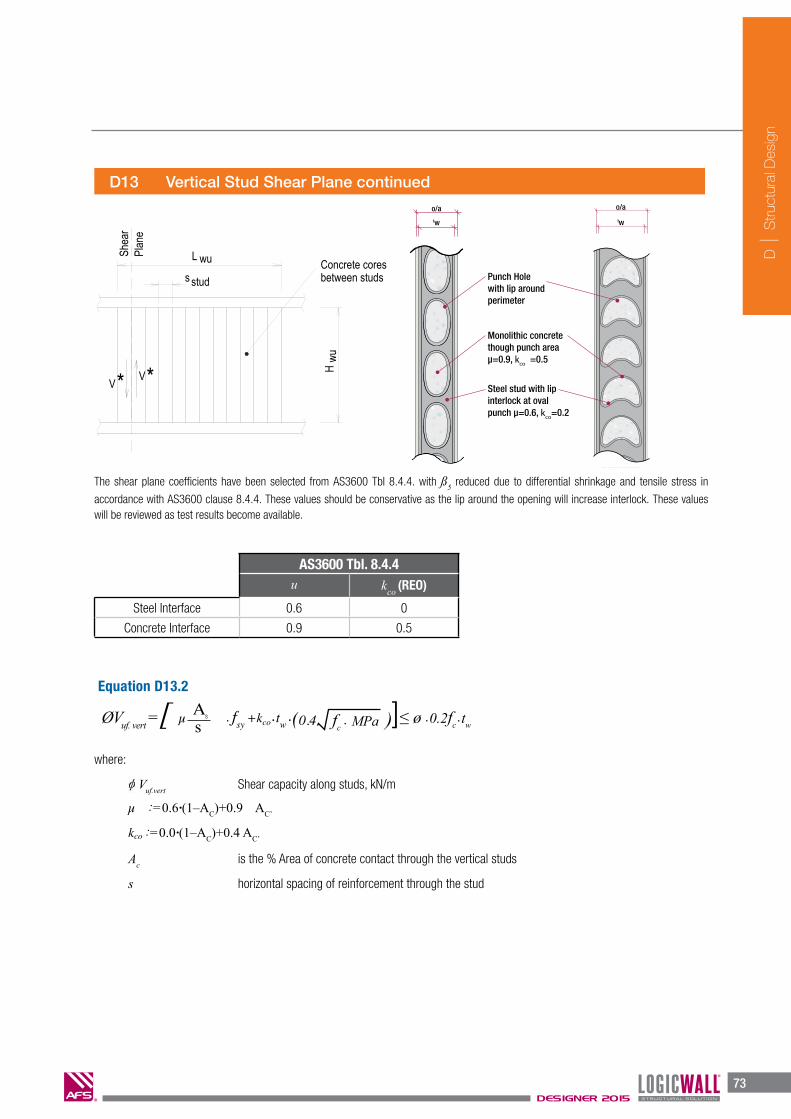
The shear plane coefficients have been selected from AS3600 TbI 8.4.4. with ß5 reduced due to differential shrinkage and tensile stress in
accordance with AS3600 clause 8.4.4. These values should be conservative as the lip around the opening will increase interlock. These values will be reviewed as test results become available.
o/atw
AFS 150
Punch Holewith lip around perimeter
Monolithic concrete though punch areau4=0.9, kco =0.5
Steel stud with lip interlock at oval punch u4=0.6, kco=0.2
Equation D13.2
where:
Vuf.vert Shear capacity along studs, kN/m
µ :=0.6·(1–AC)+0.9 AC’
kco :=0.0·(1–AC)+0.4 AC’
Ac is the % Area of concrete contact through the vertical studs
s horizontal spacing of reinforcement through the stud
AS3600 Tbl. 8.4.4u kco (REO)
Steel Interface 0.6 0
Concrete Interface 0.9 0.5
D13 Vertical Stud Shear Plane continued
ØVuf. vert =[ µ • fsy +kco • tw • (0.4 fc • MPa )As
s ]≤ ø • 0.2fc • tw
o/a
tw

D
S
truct
ural
Des
ign
74DESIGNER 2015
74DESIGNER 2012 WALLING SOLUTIONS
D
S
truc
tura
l Des
ign
D14 In Plane Horizontal Shear Capacity
vert*Vs stud
V
wuL
wuH
horiz*Plane
Shea
r
V
The strength of the AFS LOGICWALL® for in-plane horizontal shear is given by:
(Vu = Vuc + Vus) ≤ 0.2·fc·tw AS3600 [Cl 11.5.3]
The use of AFS LOGICWALL® for shear with is not recommended. If are used then
additional checks will be needed for the in-plane bending induced in the wall by the shear forces on the wall.
For walls with
Vus = pw · fsy · (0.8 · tw)
where:
Vu Ultimate in plane horizontal shear capacity. kN/m
pw Shall be the lesser of the ratios of either the vertical reinforcement area or the horizontal reinforcement area to the cross-sectional area of wall in the respective direction.
The capacity above is limited by the vertical shear component of the racking forces.
AS3600 [Cl 11.5.4 (a)]

D
S
truct
ural
Des
ign
75DESIGNER 2015
75WALLING SOLUTIONS DESIGNER 2012
D
S
truc
tura
l Des
ign
D15 Horizontal Bottom Plate Shear Plane
D16 Lintels
D17 Design As Deep Beam or Transfer Walls
Horizontal bottom plate shear is calculated using the same method by assuming a shear plane along the bottom of the stud. Except in this case there are no openings.
µ : = 0.6
kco : = 0.0
As cross-sectional area of starters crossing the bottom plate shear plane
Note: If necessary the bottom plate can be deleted to improve longitudinal shear capacity.
Lintel tables have been prepared based on the un-reinforced bending and shear capacity. If additional capacity is required then the Lintel should be designed and detailed to suit.
A number of options are available for using AFS LOGICWALL® as formwork for deep beams or transfer walls. Some of these are shown in the following examples.
Transfer walls allow the transfer of heavy loads from floors above to supporting columns or supporting beams below. These walls are designed in accordance with AS3600 Section Design of Non-Flexural Members, End Zones and Bearing Surfaces. Additional checks are to be made for Vertical Shear Plane failure at the stud, longitudinal shear at the top and bottom of the wall, development lengths, bearing and congestion.
Use of AFS LOGICWALL® in the design of deep beams should only be undertaken by experienced engineers with a good understanding of all aspects of deep beam design. The engineer should examine issues such as construction sequence, build-ability, congestion, services, detailing.
Where AS3600 calls for two layers of reinforcement AFS LOGICWALL® has two options.
a) AFS200D
b) AFS262D
kcoµ
D
S
truct
ural
Des
ign
76DESIGNER 2015
76DESIGNER 2012 WALLING SOLUTIONS
D
S
truc
tura
l Des
ign
T* bars
*
ELEVATIONSECTION
suspended slab
w
reinforcementSuspension
w*__I__I
Bearing
w
L dt
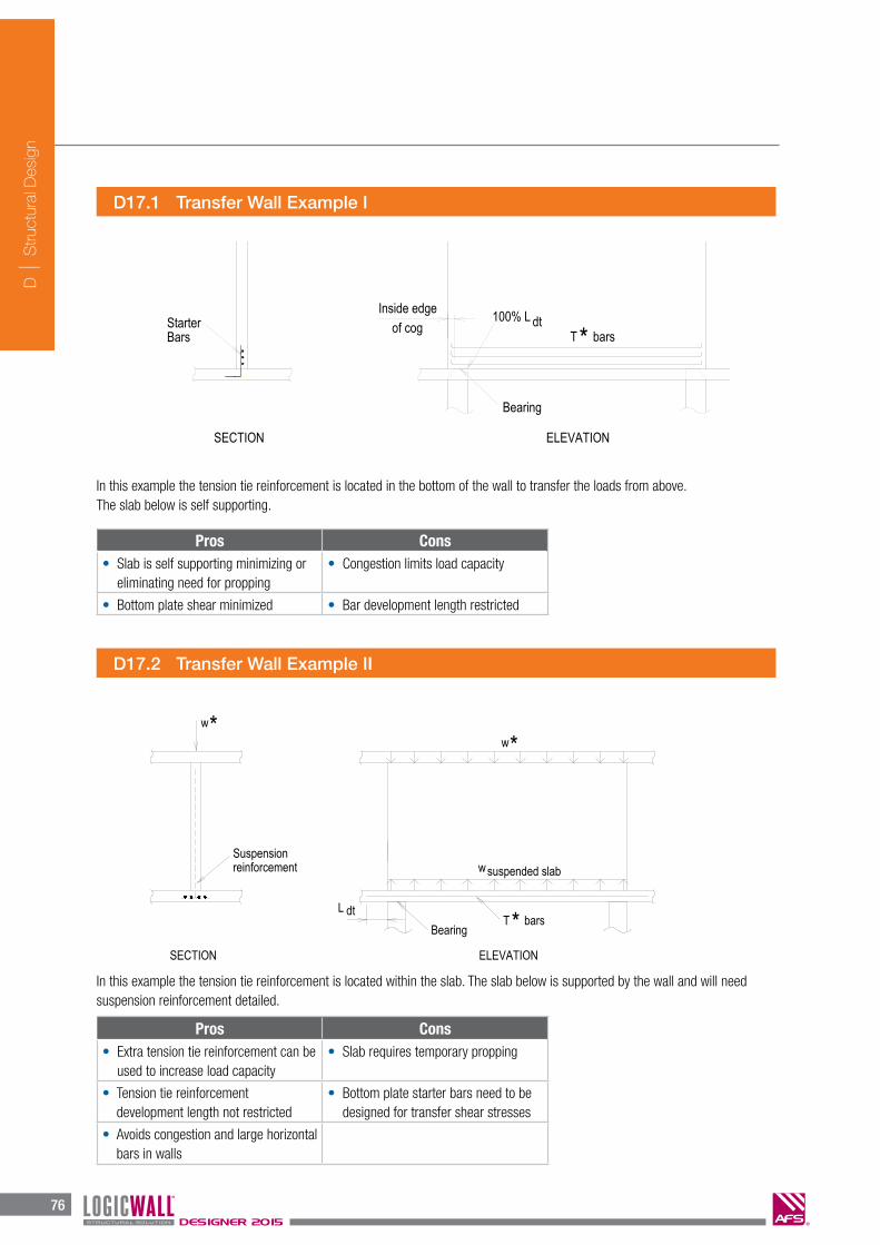
D17.1 Transfer Wall Example I
D17.2 Transfer Wall Example II
__I *w
*
bars*T
w
ELEVATION
BarsStarter
SECTION
of cog dt100% LInside edge
Bearing
In this example the tension tie reinforcement is located in the bottom of the wall to transfer the loads from above. The slab below is self supporting.
In this example the tension tie reinforcement is located within the slab. The slab below is supported by the wall and will need suspension reinforcement detailed.
Pros Cons• Slab is self supporting minimizing or
eliminating need for propping• Congestion limits load capacity
• Bottom plate shear minimized • Bar development length restricted
Pros Cons• Extra tension tie reinforcement can be
used to increase load capacity• Slab requires temporary propping
• Tension tie reinforcementdevelopment length not restricted
• Bottom plate starter bars need to bedesigned for transfer shear stresses
• Avoids congestion and large horizontalbars in walls

D
S
truct
ural
Des
ign
77DESIGNER 2015
77WALLING SOLUTIONS DESIGNER 2012
D
S
truc
tura
l Des
ign
D17.3 Transfer Wall Example III
In this example the tension tie reinforcement is located within the wall. The slab below maybe supported by a small beam to suit construction requirements.
Other combinations are possible like relocating the tension tie reinforcement from the wall in D17.3 to the beam similar to D17.2.
Multiple levels of walls can be combined to provide deeper transfer beams and extend the possible spans but require careful detailing and consideration of construction sequences . For typical spans usually only one level needs to be designed as a transfer wall.
Pros Cons• Slab is self supporting minimizing or
eliminating need for propping• Congestion limits load capacity
• Bottom plate shear minimized • Bar development length restricted

D
S
truct
ural
Des
ign
78DESIGNER 2015
78DESIGNER 2012 WALLING SOLUTIONS
D
S
truc
tura
l Des
ign
D18 Deep Beam Example
AFS LOGICWALL® can be used as permanent formwork for economical deep beams. Their design as deep beams is controlled by;
• Achievingadequatedevelopmentlengthsforthemaintensionreinforcement.
• Placementofreinforcementatthestudcutoutsandavoidingcongestion.
• Horizontaltensiontiereinforcementcanonlybecoggedtheotherendtoallowinstallationfromoneendofthewalls.AS3600requires that tension ties not be lapped in the tension zone instead full strength couplers would be needed if bars are to bejoined. For ease of construction only single length tension ties are beneficial.
• Maximisinglengthofbearingtoreducebearing,strutandshearstresses.Bearinglengthcanbeincreasedbyusingdroppanels, thicker slab, band beams.
Additional storeys can be used to increase span and load capacity of deep beams. The detailing at each floor will need adequate continuity bars through the slab into the wall as starter bars.
In order to calculate the loads we need to select some preliminary trial values for the effective length of bearing on the slab and the depth of the compression strut at the top of Ihe wall The value of the bearing length will be adjusted until we achieve acceptable design stresses. An allowance is also included for the tension tie to be raised above the bottom of the wall, this will allow the centroid of the tension tie bars to be raised since the location of the cutouts and the bars selected may result in a higher placement within the wall.
1bearing
= 520 mm Length of bearing below wall
dcomp
:= 62 mm Depth of compression strut at top of wall
dbase
:= l00 mm The distance from the slab to the bottom of the tension tie
Typically multiple levels of AFS walls will span an opening. Normally only the lower one or two levels are designed as deep beams. This simplifies the design and construction as additional documentation and reinforcement is limited to the lower walls. Propping can also be removed earlier avoiding staged construction design. In the final construction state this is conservative as effective depth of the deep beam is greater.
The following is an example of a Type I idealized Strut and Tie Design Model utilising a Fan Strut to support uniformly distributed design load. Design of Non-flexural Members should only be undertaken by experienced engineers familiar with Strut and Tie design in accordance with AS3600 Section 12 or other appropriate references.
lb Length of bearing below wall
dbase
The distance from the slab to the bottom of the tension tie
H Floor - Floor Height
Lclear
Clear Span
∂
lb
lbBeam/Capital
w*
Tension Tie d base
column
H
column
CCT Node
CCC Node
TYPE I(b) Fan Strut (no bursting forces)[Refer AS 3600-2009 - Fig 7.2.1]
L clear
L supported

D
S
truct
ural
Des
ign
79DESIGNER 2015
fbearing = b • 0.9 f’c •
fstrut = stbs 0.9 f’c Ac
within limits 0.3 < bs ≤ 1.0
bn = 0.8 for CCT Node
fnode= bn 0.9 f’c
< b • 1.8 • f’c
79WALLING SOLUTIONS DESIGNER 2012
D
S
truc
tura
l Des
ign
D18 Example continued
Note that the vertical loads beyond the bearing length being considered will transfer vertically direct to the column below and will not be included in the calculation of strut and tie forces. The reaction on the bearing length at the slab level will be
By geometry or calculation we can determine the depth of the tension tie zone at the bottom of the wall dtens
=229 mm, and by statics the load in the tension tie T
u=503 kN. Minimum tension tie reo will require additional checks for crack control:
The maximum strut stress occurs at edge of the bearing surface. The vertical component of this stress is simply the reaction over the horizontal bearing surface. Resolving this to diagonal stress at the edge gives:
or 842.5 kN: (0.5 )L u clear slab bearingR L t lω= ⋅ ⋅ − +
2
1
2
1
0.85 2
1 20.4
: 9.679
bearing b c b c
bearing
Lbearing bearing
bearing w
Af f fA
Awith f MPaA
Rf f MPal t
φ φ φ
φ
= ⋅ ⋅ ⋅ ⋅
= =
= =⋅
< Allowable bearing at support.
Adopt 4N24-200 HOR BTM.2: 1438utie tie
st y
TA A mmfφ
= =⋅
.max. .max.
2 2
.
.
1: 9.5
( ) (0.5 ) 1:
13.2
: 0.8200
16.8
Lstrut v strut v
bearing base w
wu comp base clear slab baseLstrut
bearing base wu comp base w
strut
cc cal st c
c cal
Rf f Mpal d t
H d d L t dRfl d H d d t
f Mpa
ff fMPa
f
φ φ
φ
= ⋅ =+
− − + ⋅ − −= ⋅ ⋅
+ − −
=
= − ⋅
=
1(0.5 ): 237.5clear slabvert u vert
wu
MPa
L tV V kNH
ω −−= ⋅ = ⋅
The maximum share then along the vertical stud plane is:
N16-400 + 4N24 is equivalent to N20-280 giving capacity of greater than 284kN/m.
Note that the vertical loads beyond the bearing length being considered will transfer vertically direct to the column below and will not be included in the calculation of strut and tie forces. The reaction on the bearing length at the slab level will be
By geometry or calculation we can determine the depth of the tension tie zone at the bottom of the wall and by statics the load in the tension tie. Minimum tension tie reo will require additional checks for crack control:
Allowable bearing at support. [ 12.6 ]
[ 7.2.3 ]
[ 7.2.2 ]
[ 7.4.2 ]
or 842.5kN
The maximum strut stress occurs at edge of the bearing surface. The vertical component of this stress is simply the reaction over the horizontal bearing surface. Resolving this to diagonal stress at the edge gives:
The maximum share then along the vertical stud plane is:
Atie :=
bs :=
RL := wu
• (0.5 • L
supported )
Tu
st • f y
1
1.0 + 0.66 cot2q
A2
A1
vvert := wu
•( 0.5L
clear – tslab )
Hwu

D
S
truct
ural
Des
ign
80DESIGNER 2015
80DESIGNER 2012 WALLING SOLUTIONS
D
S
truc
tura
l Des
ign
Finally check the development length of the tension tie reinforcement is adequate. For this wall we will use a standard cog to give half L.sy. with the remainder being the length from the standard cog to the left hand side of the assumed bearing surface.
The individual cells within AFS LOGICWALL® allow horizontal shrinkage and thermal movements in the concrete with the internal studs acting as crack inducers. This allows AFS LOGICWALL to provide crack control without additional reinforcement. The vertical studs can be considered as non fire-rated vertical reinforcement.
For fire-rated reinforced walls to AS3600 11.6.1 use minimum vertical reinforcement ratio (pw) of 0.0015 or the value required by
structural analysis.
Due to the presence of the steel studs in AFS LOGICWALL® steel congestion should be avoided to facilitate adequate compaction of concrete. As a guide steel ratios in excess of 0.02 in a single layer should not be used unless the amount and disposition of the reinforcement will not prevent the proper placement and compaction of the concrete at splices and at junctions of members.
For walls required that have tensile forces from any load combination AS3600 11.6 Minimum reinforcement shall apply. Examples of such walls are:
� Walls resisting lateral loads� Walls acting as deep beams� Walls with load combinations of bending and compression producing tension stress.� Where reinforced AFS LOGICWALL walls do not require a high degree of crack control for tensile forces we recommend a
minimum reinforcement spacing of 400mm.� Horizontal reinforcement may be reduced to zero for walls supporting vertical loads only where the wall is designed for one way
buckling and the studs act as crack inducers for removing restraint against horizontal shrinkage or thermal movement.
Notes: AS3600 does not recognise the use of plain concrete in wall elements, though some International standards offer guidance in this area. Use of AFS LOGICWALL® walls unreinforced will require reference to other codes such as ACI 318 and BS8110.1 where it can be shown that no tensile forces result from any load combination of bending and compression.
21 2
1 3. 1
2
11, 2.4, : 450 , : (150 24) , : 242
0.529 600
': 1000 25 8 413
0.5 300 .
b b
sy bsy tb b sy
c
available bearing slab b available
sy sy
k k A mm a mm d mm
k k f dL k d L mm
k fL mm l t mm d L mm
L L mm Ok
= = = = ⋅ − =
= ≥ =
= − + − − ⋅ =
− ⋅ =
Using a standard cog then the development length required is:
D19 Reinforcement Requirements
D20 Minimum Reinforcement
D18 Example continued
Finally check the development length of the tension tie reinforcement is adequate with at least 50% extending beyond the node using either straight bar or standard cogs. Welded or mechanical anchorages are not normally used. [ 7.3.3 ]

D
S
truct
ural
Des
ign
81DESIGNER 2015
81WALLING SOLUTIONS DESIGNER 2012
D
S
truc
tura
l Des
ign
For heavy loaded walls where reinforcement content is high, it is critical that reinforcement is detailed carefully to avoid congestion within the wall which creates difficulties when core filling and may result in voids or insufficient concrete compaction.
When detailing reinforcement to be placed in AFS LOGICWALL® the following constraints must be noted.
Reinforcement Spacing In Panels
� For single reinforcement carrier walls (AFS120, 150, 162 & 200) the reinforcement is centrally placed at minimum 200mm centres horizontally.
AS1170.4 Earthquake Actions in Australia
5.2.3 Performance under earthquake deformations states:
Stiff components (such as concrete, masonry, brick, precast concrete walls or panels or stairwells, stairs and ramps) shall be –
(a) considered to be part of the seismic-force-resisting system and designed accordingly;
or
(b) separated from all structural elements such that no interaction takes place as the structure undergoesdeflections due to the earthquake effects determined in accordance with this Standard.
Note: The above provisions are considered to also apply to the use of non-ductile plain concrete members and the designer of un-reinforced AFS LOGICWALL® walls shall consider these in the design. In addition AS3700 provides guidance restricting the use of unreinforced masonry (non-ductile walls) for tall buildings. We would recommend AS3700-2001 Amendment No 3 Table AA3 be considered for AFS LOGICWALL® walls.
AS3700-2001 Amendment No 3 Table AA3 Height Limits for Buildings with Load bearing Unreinforced Masonry (non-ductile) to a maximum height ranging from 10 to 15 metres.
D22 Reinforcement Detailing Constraints
120mm
AFS 120
108mm
70mm
6mm6mm
19mm
50mm30mm
170mm
30mm
200mm
200mm
19mm
Fig D22.1
D21 Earthquake Actions

D
S
truct
ural
Des
ign
82DESIGNER 2015
82DESIGNER 2012 WALLING SOLUTIONS
D
S
truc
tura
l Des
ign
Draft v6 29/11/11
Factory installed corner bars as per engineer’s specifications
90º (+-8º)
Horizontal bar lap to engineer’s details
Detail #11
AFS 90º Prefabricated Corner
� For double reinforcement carrier walls, AFS200D and 262D, the reinforcement is located at each face of the wall with concrete cover as shown in figures D22.2 and D22.3.
D22 Reinforcement Detailing Constraints continued
Fig D22.2 - AFS200D Fig D22.3 - AFS262D
Fig D22.8
Corner Reinforcement
Reinforcement in corner panels is factory fitted and consists of the following.
� Single Reinforcement Carrier Walls - a single ‘L’ bar is placed at minimum 200mm centres for horizontal reinforcement only. Refer to structural engineers details / requirements.
200mm
AFS 200D
188mm
115mm
6mm6mm
37mm
50mm30mm
160mm
40mm
200mm
200mm
200mm
37mm
262mm
AFS 262D
250mm
211mm
6mm6mm
19.5mm
50mm
160mm
200mm
200mm
19.5mm
750mm (max)
Fig D22.2 - AFS200D
Standard Wall Junctions Fig D22.4
Fig D22.3 - AFS262D
WALLING SOLUTIONS DESIGNER 2012
39
C
Pro
per
ties
Fig. C2.2.B 108 StudAFS 120
Fig. C2.2.C 136 StudAFS 150
Fig. C2.2.D 150 StudAFS162
Fig. C2.2.E 188 StudAFS 200
Fig. C2.2.G 250D StudAFS 262D
Fig. C2.2.F 188D StudAFS 200D
120mm
AFS 120
108mm
70mm
6mm6mm
19mm
50mm30mm
170mm
30mm
200mm
200mm
19mm
148mm
AFS 150
136mm
100mm
6mm6mm
18mm
50mm
30mm
170mm
30mm
200mm
200mm
18mm
200mm
188mm
134mm
6mm6mm
33mm
50mm
166mm
200mm
200mm
200mm
33mm
162mm
AFS 162
150mm
100mm
6mm6mm
25mm
50mm30mm
170mm
30mm
200mm
200mm
25mm
262mm
AFS 262D
250mm
211mm
6mm6mm
19.5mm
50mm
160mm
200mm
200mm
19.5mm
47.1% 52.3%
C2.2 Steel Stud Spacing continued
CONCRETE CONTACT AREA
CONCRETE CONTACT AREA 47.2%
CONCRETE CONTACT AREA
50.0%CONCRETE CONTACT AREA 49.5%
CONCRETE CONTACT AREA
200mm
AFS 200D
188mm
115mm
6mm6mm
37mm
50mm30mm
160mm
40mm
200mm
200mm
200mm
37mm
50.0%CONCRETE CONTACT AREA
200mm

D
S
truct
ural
Des
ign
83DESIGNER 2015
83WALLING SOLUTIONS DESIGNER 2012
D
S
truc
tura
l Des
ign
D22 Reinforcement Detailing Constraints continued
AFS LOGICWALL
AFS LOGICWALL
Fig D22.10
Fig D22.9
�
750mm (max)
750mm (max)
Double Reinforcement Carriers - two ‘U’ bars are lapped in the corner panel at minimum 200mm centres, as shown in figure 22.9. Alternatively three ‘L’ bars can be installed, one being lapped from the inside bar to the outside bar as shown as shown in D22.10. Refer to structural engineers details / requirements.
Standard Wall Junctions Fig D22.5
Special Wall Junctions (when specified by an engineer) Fig D22.6

D
S
truct
ural
Des
ign
84DESIGNER 2015
82DESIGNER 2012 WALLING SOLUTIONS
D
S
truc
tura
l Des
ign
Draft v6 29/11/11
Factory installed corner bars as per engineer’s specifications
90º (+-8º)
Horizontal bar lap to engineer’s details
Detail #11
AFS 90º Prefabricated Corner
� For double reinforcement carrier walls, AFS200D and 262D, the reinforcement is located at each face of the wall with concrete cover as shown in figures D22.2 and D22.3.
D22 Reinforcement Detailing Constraints continued
Fig D22.2 - AFS200D Fig D22.3 - AFS262D
Fig D22.8
Corner Reinforcement
Reinforcement in corner panels is factory fitted and consists of the following.
� Single Reinforcement Carrier Walls - a single ‘L’ bar is placed at minimum 200mm centres for horizontal reinforcement only. Refer to structural engineers details / requirements.
200mm
AFS 200D
188mm
115mm
6mm6mm
37mm
50mm30mm
160mm
40mm
200mm
200mm
200mm
37mm
262mm
AFS 262D
250mm
211mm
6mm6mm
19.5mm
50mm
160mm
200mm
200mm
19.5mm
750mm (max)
Wall Junctions Fig D22.7

D
S
truct
ural
Des
ign
85DESIGNER 2015
83WALLING SOLUTIONS DESIGNER 2012
D
S
truc
tura
l Des
ign
D22 Reinforcement Detailing Constraints continued
AFS LOGICWALL
AFS LOGICWALL
Fig D22.10
Fig D22.9
�
750mm (max)
750mm (max)
Double Reinforcement Carriers - two ‘U’ bars are lapped in the corner panel at minimum 200mm centres, as shown in figure 22.9. Alternatively three ‘L’ bars can be installed, one being lapped from the inside bar to the outside bar as shown as shown in D22.10. Refer to structural engineers details / requirements.
Horizontal wall reinforcement is not to project into corner

D
S
truct
ural
Des
ign
86DESIGNER 2015
84DESIGNER 2012 WALLING SOLUTIONS
D
S
truc
tura
l Des
ign
The structural concrete wall effectively has control joints at each stud so no additional crack control joints are necessary. Full depth "movement joints" may be required depending on the geometry of the structure and other considerations such as thermal loads, exposure and buiIding joints. In generaI "movement joints" would not be required for walls less than 16m long. Structural movement joints will be placed in locations nominated by the structural engineer and must be documented on structural drawings. These will be installed at construction stage by the AFS LOGICWALL® installation contractor. The following method is recommended:
D23 Movement Joints
Draft v6 29/11/11
Detail #16
Structural Movement Joint
AFS LOGICWALL AFS LOGICWALL Prefabricated AFS endcap stud site installed by AFS LOGICWALLinstallation contractor.
Backing strip and fire rated sealant.
Fig D23.1
Fig D22.11
Note: Can be dowel jointed if required structurally. Must be clearly specified and negotiated with installers at time of tender. Installed where nominated by project engineer. Must be clearly documented on drawings. Typically not required in walls less than 16m in length.
D22 Reinforcement Detailing Constraints continued
Ligatures
� When detailing ligatures within the AFS LOGICWALL® panels care must be taken to ensure the ligatures fit within the parameters governed by the holes in the steel stud framework. See example below - Fig. D22.11 for AFS 262D.
Steel Ligature
Variable Length
180mm262mm
AFS LOGICWALL Steel Stud Members
Fibre Cement Sheet

D
S
truct
ural
Des
ign
87DESIGNER 2015
85WALLING SOLUTIONS DESIGNER 2012
D
S
truc
tura
l Des
ign
D24 Sheet Surface Joints
D25 Wall Bracing
D26 Structural Detailing
Sheet surface joints are 6mm deep, (i.e. the full depth of the fibre cement sheeting) to accommodate expansion in the fibre cement sheet. These are placed at max 6.0 m centres at finishing stage, i.e. after wall is concrete filled at time of setting the vertical recessed joints. Locations of sheet surface joints should be nominated by the architect, as they can often be concealed behind glazing sections or cupboards. The following method is recommended:
During construction AFS LOGICWALL® panels shall remain braced until the floor over is constructed. Typical spacing for panel braces is 1100mm which is every panel joint, bracing charts are available upon request. Apply standard bracing details for temporary construction wind loadings up to Terrain Category 2 for 3000mm high walls placed on floors up to 50m above ground level. The nominated Project Engineer is to design and detail any additional braces required for non-standard application.
Further details on bracing are in Section K ‘Installation’ of this manual.
Care must be taken when detailing AFS LOGICWALL® to avoid installation problems on site. Points to note are:
� Location and detailing of starter bars.� Cast in starter bars or drilled in dowels with limited anchorage.� Location and size of reinforcement to avoid steel congestion and placement difficulties.� Allow for location of services such as conduits and junction boxes within walls. Care is needed to avoid damage to junction
boxes if heavy horizontal reinforcement is used.� Services within walls should be avoided in highly stressed areas or allowed for in the design.� Maximum supplied wall height 4200mm. Heights exceeding 4200mm can be manufactured upon request and will be regarded
as a special order.
Fig D24.1
Draft v6 29/11/11
Joint taped and set in accordance with manufacturer’s specifications.
Cut for expansion joint aftersetting is complete (2-4mm wide through depth of the fibre cement sheet). Fill groove with paintable flexible sealant.
Detail #17
Fibre Cement Sheet Surface Joint
AFS LOGICWALL

D
S
truct
ural
Des
ign
88DESIGNER 2015
86DESIGNER 2012 WALLING SOLUTIONS
D
S
truc
tura
l Des
ign
D26 Structural Detailing continued
D27 Core Fill Compaction
The concrete supplier is responsible to provide a mix design that is suitable for filling AFS LOGICWALL®.
The concrete core fill mix must be designed with enhanced flow characteristics. Such concrete is available from Hanson Concrete and most other concrete suppliers.
AFS trial and experience have shown that a concrete mix that is designed such that segregation and blowouts are prevented whilst achieving the required level of compaction will have the following basic characteristics:
� f’c=25 to 50 MPa (to be as specified by the project structural engineer).
� 7-10mm maximum aggregate.� Batched at 80mm slump before admixtures.� Admixtures including plasticiser and flyash are used
to increase the slump to 140 – 160mm. Slump is to be measured and discharged from the truck to AS1379 requirements.
� Pumpable for delivery via a 50mm diameter hose, with continuous flow.
� Pours limited to 1500mm high lift per pass. Allow sufficient time between passes, to allow the concrete of the previous pass to ‘gel’. (Typically 1/
2 hour or longer). Refer Chapter K
Section K6.6 – ‘Concrete Delivery and Placement’ for ‘gel’ test precedure.� Vibrated with a 40mm diameter needle vibrator by placing
the vibrator in the upper 300mm of the wall panel and rattling the steel stud framework and reinforcement bars.
Note: Over vibrating can result in bulges and/or blowouts. Do not touch the fibre cement sheets with the vibrator. Keep vibration to a minimum.
To assist with designing and detailing walls using AFS LOGICWALL®, AFS provide a complete package of standard details, library parts, wall families and 3D model objects in the following BIM and file types.
� Revit� Archicad� DWG� PDF (STD Details)
The concrete mix is critical to the successful outcome of filling AFS LOGICWALL®
D
S
truct
ural
Des
ign
89DESIGNER 2015
87WALLING SOLUTIONS DESIGNER 2012
D
S
truc
tura
l Des
ign
D28 AFS and Natspec
Natspec is a not-for-profit organisation that is owned by the design, build, construct and property industr y through professional associations and government property groups. Natspec’s major service is the comprehensive national specification system endorsed by government and professional bodies.The specification is for all building structures with specialist packages for architects, interior designers, landscape architects, structural, mechanical, hydraulic and electrical engineers and domestic owners.
The foundation of the Natspec specification system is the ‘worksection’. Natspec worksections are selected and customized by the specifier to produce a project specification. In some instances, the specifier can choose between a generic worksection and a branded worksection when compiling the specification.
A Natspec branded worksection is developed by Natspec in conjunction with the manufacturer, known as a Natspec Product Partner. AFS has worked extensively with Natspec to become a product partner and to form the ‘AFS LOGICWALL® In Concrete Combined’ branded worksection.
This AFS LOGICWALL® product specific worksection/specification can be accessed via a link on the AFS website – www.afswall.com.au or by going directly to the Natspec website – www.natspec.com.au and has been formulated so that project designers/specifiers can produce a project specific specification for either:
1. AFS LOGICWALL combined with all concrete works on the project or
2. AFS LOGICWALL component of the project only.

D
S
truct
ural
Des
ign
90DESIGNER 2015
D Notes

D
S
truct
ural
Des
ign
DESIGNER 2015W
D Legal Statements
IMPORTANT LEGAL STATEMENTS
Reasonable efforts have been made to ensure the accuracy of this publication; however, any information and data contained herein is subject to change without notice. To ensure the information you are using is correct, AFS recommends you review the latest technical information available on the AFS website www.afswall.com.au, or alternatively call 1300 727 237 to speak to a Technical Representative.
The AFS logo and LOGICWALL® mark are registered trade marks. © 2015 AFS Systems Pty Ltd. No part of this publication may be reproduced in any form or by any means without prior written permission from AFS Systems Pty Ltd. All rights reserved.
DISCLAIMER
1. This technical manual named AFS Designer together with the design tables and associated information related to AFS LOGICWALL® has been prepared by AFS to assist design professionals using AFS LOGICWALL® including without limitation, developers, builders, engineers, architects or quantity surveyors with the design of structural walls.
2. It is the responsibility of the user to ensure that the use of this manual is appropriate and to exercise their own judgment when using this manual.
3. AFS does not accept any responsibility (whether for negligence or otherwise) for any consequence arising from the use or application of this manual.
4. The design and engineering of the structure of any building using AFS LOGICWALL® should only be undertaken by suitability qualified and experienced design professionals, engineers or consultants.
5. The full responsibility for the design, engineering and structural design, and certification of compliance with all relevant Australian Standards, BCA and any other statutory requirements at Local, State and Federal levels rest with the design professional, project engineer or project consultants including but not limited to the design engineer, acoustic consultant, energy efficiency consultant, fire engineer and any of their officers, employees, delegates, partners, agents and service providers of any nature.
6. AFS reserves the right to change the specifications of this manual without notice.
7. Please check with AFS that you have the latest version as the manual may be updated from time to time and certain details may change.
8. This disclaimer applies to the extent permitted by law.
DEFINITIONS
The use of the terms ‘AFS LOGICWALL®’ and ‘AFS LOGICWALL® Walls’ throughout the AFS Designer are as follows;
AFS LOGICWALL®: Refers to AFS LOGICWALL® panels as permanent formwork prior to being installed & corefilled with concrete.
AFS LOGICWALL® Walls: Refers to AFS LOGICWALL® walls installed with concrete corefill incorporated.

IMPORTANT LEGAL INFORMATIONReasonable efforts have been made to ensure the accuracy of this publication; however, any information and data contained herein is subject to change without notice. To ensure the information you are using is correct, AFS recommends you review the latest technical information available on the AFS website www.afswall.com.au, or alternatively call 1300 727 237 to speak to a Technical Representative.
The AFS logo and LOGICWALL® mark are registered trade marks. © 2015 AFS Systems Pty Ltd. No part of this publication may be reproduced in any form or by any means without prior written permission from AFS Systems Pty Ltd. All rights reserved.
Distributed by:
AFS SYSTEMS PTY LTDPO Box 234, Minto NSW 2566110 Airds Road, Minto NSW 2566Phone: 1300 727 237Email: [email protected]: www.afswall.com.au ABN 45 576 072 788


