Steel Innovations Conference 2013 Christchurch, New Zealand 21-22 February 2013 HYSTERESIS CHARACTERSTICS OF CIRCULAR PIPE STEEL DAMPER USING LYP225 D. Y. Abebe 1 , J. W. Kim 2 , and J. H. Choi 3† ABSTRACT This study aims to identify the hysteresis characteristics of circular pipe steel damper (CPD) with low yield point steel (LYP225). CPD is used to dissipate energy by metallic deformation due to the geometrical elasticity of circular shape and fatigue resistance around connection part. Steel dampers are a widely used energy dissipating device as they are easy to install, maintain and inexpensive. CPD is among these steel dampers, so its hysteresis characteristics and deformation behavior need to be predicted accurately for controlling the seismic performance of structures in which it is used. Nonlinear explicit FE analysis has been carried out to evaluate the structural performance of CPD using LYP225 in this study. The analysis specimen was modeled after the effective size, at which both bending and shear stress are occurred simultaneously, are determined by simple engineering mechanics which is found to be aspect ratio (height to diameter ratio) of √3 . In addition, cyclic loading test was carried out to verify the FE analysis results. Furthermore, to investigate the advantage of using low yield point steel over conventional steel (SS400) as damping material, both analysis and test was also conducted for (SS400) to compare the deformation and hysteresis characteristics with LYP225. After comparison of the two results it is noted that the explicit FE analysis was accurately determine the large deformation and stress-strain relationship as well as can calculate the cumulative energy from to cyclic loading. Keyword: low-yield point steel, circular pipe damper, cyclic loading, large deformation, FE analysis, Introduction Recently structural control has paid much attention to seismic design, with the premise that such control can improve ultimate resisting capacity of structures and reduce damage during earthquake. A hysteretic damper is a type of passive control device which uses the hysteresis of the material of the damper as the source of energy dissipation. A disadvantage of such dampers is that they absorb seismic energy only when they go through inelastic deformation. The circular pipe dampers are also dissipate seismic energy through inelastic deformation and fatigue resistance of the welded part. To overcome this restriction of hysteretic dampers, low yield strength steel is used as the material for hysteretic damper [Nakashima, 1995 and Shimokawa, 1998]. Low yield point steel preferred over the conventional steel to be used as seismic energy dissipating device is because it has high elongation capacity though the yield strength is low. The CPD with low yield point steel is excellent ductility performance. That is why the use of low yield point steel as energy dissipating device became a significantly important as low yield point steel has a capacity of high deformation. The action force during earthquake is CPD is so multi-dimensional, the CPD in the practical situation can resist load in all directions. In order to evaluate the load resisting capacity and hysteresis behavior of CPD both experimental and nonlinear finite element analysis were carried out in this study. For further investigation CPD of the same size that composed of conventional steel compared with low yield point steel damper. Both the chemical and mechanical properties of specimen are presented in table 1 and 2 respectively. The mechanical properties of specimen are measured through coupon test and the stress-strain relationship is drawn as shown in fig. 1. 1 Graduate Student, Dept. of Architectural Engineering, University of Chosun, Gwangju, Korea, 501-759 2 Senior Researcher, Development of Smart Green Construction Technology, University of Chosun, Gwangju, Korea, 501-759 3 Associate Professor, School of Architectural Engineering, University of Chosun, Gwangju, Korea, 501-759
Transcript
Steel Innovations Conference 2013
Christchurch, New Zealand 21-22 February 2013
HYSTERESIS CHARACTERSTICS OF CIRCULAR PIPE STEEL DAMPER USING LYP225
D. Y. Abebe1, J. W. Kim2, and J. H. Choi3†
ABSTRACT This study aims to identify the hysteresis characteristics of circular pipe steel damper (CPD) with low yield point steel (LYP225). CPD is used to dissipate energy by metallic deformation due to the geometrical elasticity of circular shape and fatigue resistance around connection part. Steel dampers are a widely used energy dissipating device as they are easy to install, maintain and inexpensive. CPD is among these steel dampers, so its hysteresis characteristics and deformation behavior need to be predicted accurately for controlling the seismic performance of structures in which it is used. Nonlinear explicit FE analysis has been carried out to evaluate the structural performance of CPD using LYP225 in this study. The analysis specimen was modeled after the effective size, at which both bending and shear stress are occurred simultaneously, are determined by simple engineering mechanics which is found to be aspect ratio (height to diameter ratio) of √3. In addition, cyclic loading test was carried out to verify the FE analysis results. Furthermore, to investigate the advantage of using low yield point steel over conventional steel (SS400) as damping material, both analysis and test was also conducted for (SS400) to compare the deformation and hysteresis characteristics with LYP225. After comparison of the two results it is noted that the explicit FE analysis was accurately determine the large deformation and stress-strain relationship as well as can calculate the cumulative energy from to cyclic loading. Keyword: low-yield point steel, circular pipe damper, cyclic loading, large deformation, FE analysis,
Introduction Recently structural control has paid much attention to seismic design, with the premise that such control
can improve ultimate resisting capacity of structures and reduce damage during earthquake. A hysteretic damper is a type of passive control device which uses the hysteresis of the material of the damper as the source of energy dissipation. A disadvantage of such dampers is that they absorb seismic energy only when they go through inelastic deformation. The circular pipe dampers are also dissipate seismic energy through inelastic deformation and fatigue resistance of the welded part. To overcome this restriction of hysteretic dampers, low yield strength steel is used as the material for hysteretic damper [Nakashima, 1995 and Shimokawa, 1998]. Low yield point steel preferred over the conventional steel to be used as seismic energy dissipating device is because it has high elongation capacity though the yield strength is low. The CPD with low yield point steel is excellent ductility performance. That is why the use of low yield point steel as energy dissipating device became a significantly important as low yield point steel has a capacity of high deformation. The action force during earthquake is CPD is so multi-dimensional, the CPD in the practical situation can resist load in all directions. In order to evaluate the load resisting capacity and hysteresis behavior of CPD both experimental and nonlinear finite element analysis were carried out in this study. For further investigation CPD of the same size that composed of conventional steel compared with low
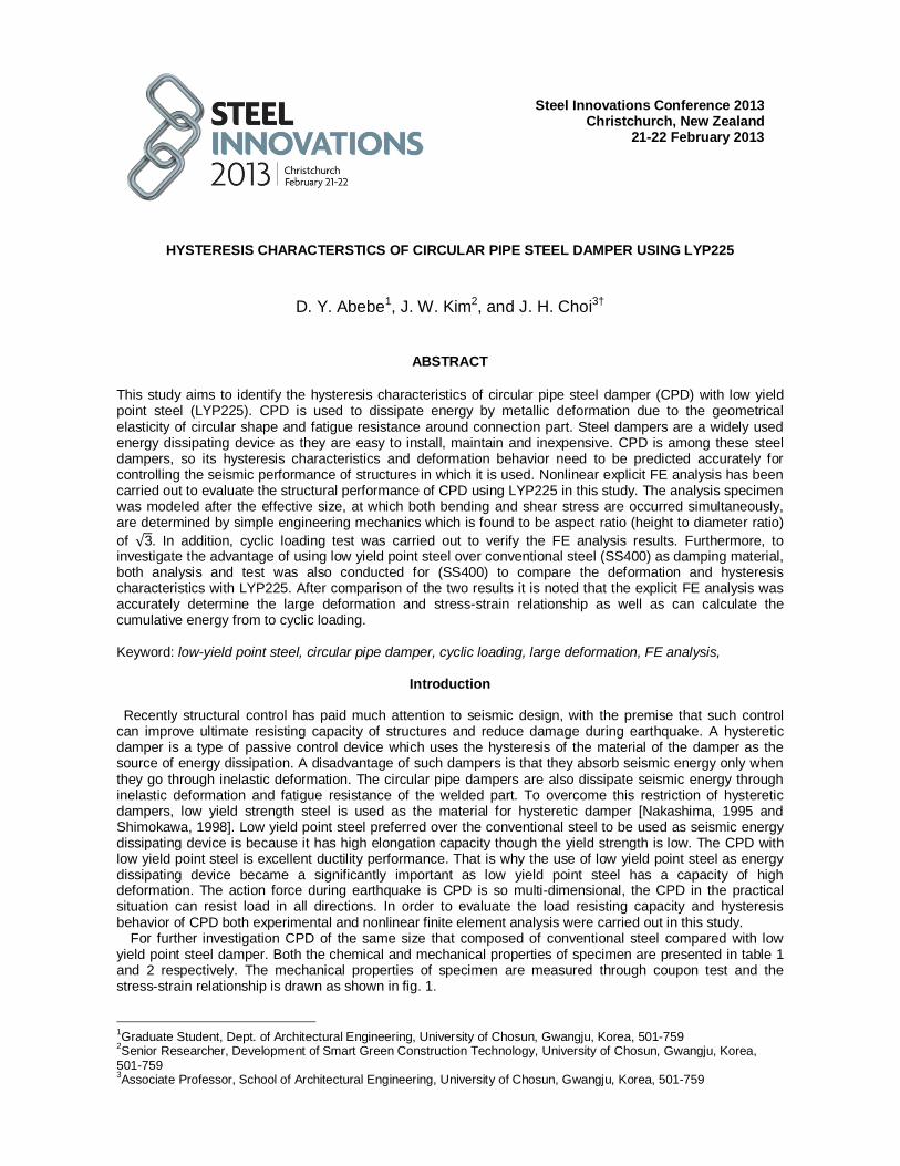
yield point steel damper. Both the chemical and mechanical properties of specimen are presented in table 1 and 2 respectively. The mechanical properties of specimen are measured through coupon test and the stress-strain relationship is drawn as shown in fig. 1. 1Graduate Student, Dept. of Architectural Engineering, University of Chosun, Gwangju, Korea, 501-759 2Senior Researcher, Development of Smart Green Construction Technology, University of Chosun, Gwangju, Korea, 501-759 3Associate Professor, School of Architectural Engineering, University of Chosun, Gwangju, Korea, 501-759
Table 1. Chemical composition of steels used
Material C Si Mn P S N LYP225 ≤0.01 ≤0.03 ≤0.2 ≤0.025 ≤0.015 ≤0.006 SS400 0.13 0.01 0.47 0.011 0.009 -
Before start investigation of hysteresis behavior, it needs to identify the effective size of CPD, the size at
which the developed stresses, both bending and shear stresses are resisted equally. The important parameter in fixing the size is the aspect ratio (diameter to height ratio). Theoretically the whole system of CPD is considered as a fixed ended beam as presented in fig. 2. The corresponding bending stress and shear stress distribution on the cross-section is shown in fig. 3(a), (b) respectively.
Fig. 2. Loading condition and bending moment diagram
0
100
200
300
400
500
0 10 20 30 40 50 60
σ (N
/mm
2 )
ε (%)
SS400 LYP225
σy=369 (N/mm2)
σu=411 (N/mm2)
σy=202.6(N/mm2)
σu=265.4(N/mm2)
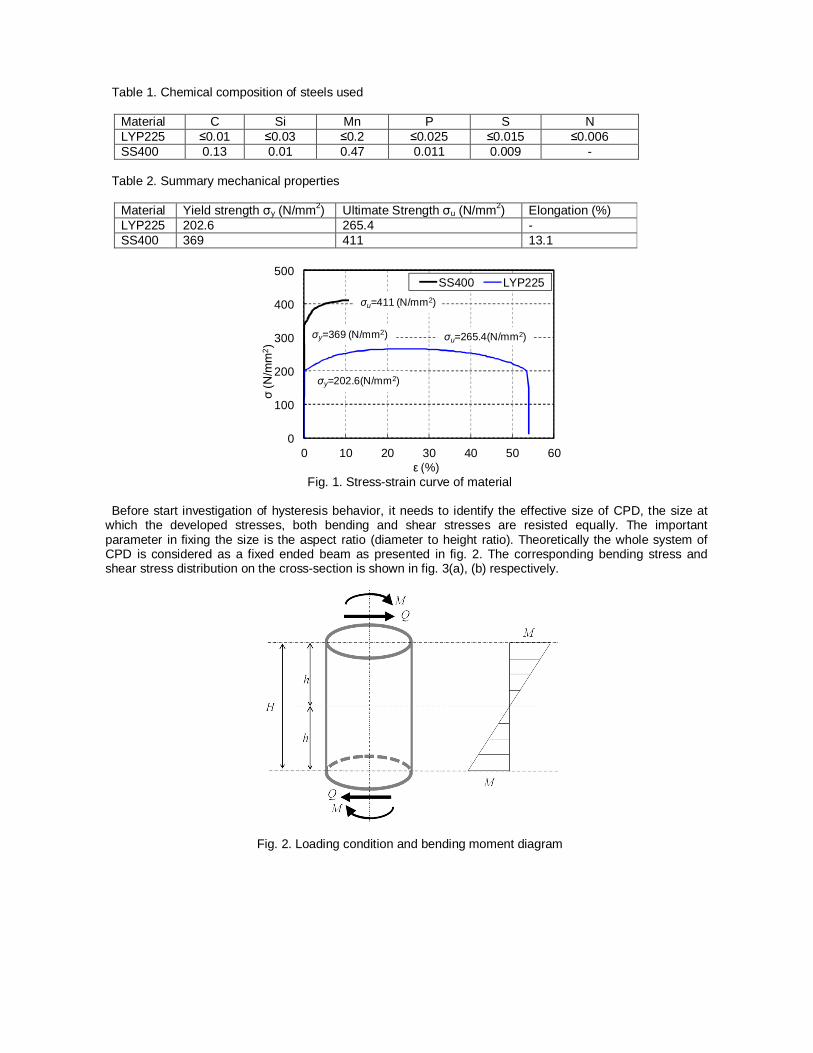
Fig. 3. Bending and Shear stress distribution By taking infinitesimal length, as shown in fig. 4, the bending stress is given by:
Fig. 4. Stress distribution on the infinitesimal length σθ= M
Iy(1)
where: M: bending moment
y: the distance of the area from the neutral axis and is given by푦 = 푟 sin휃 I: second moment area given by 퐼 = 휋r t
Substituting y and I in equation (1), the bending will be휎 = sin θ; the bending stress is maximum for휃 = , 휎 = (2)
whereas the shear stress (τ) is defined as:τ = cos휃substituting for 퐼 = 휋푟 푡 and 푄 = then the
shear stress will be: 휏 = ∗ 푐표푠 휃(3) Shear stress is maximum for θ = 0o, at which the cosθ=1, then 휏 = (4) The uni-axial and shear yield stresses for the von Mises criterion [7] are related by 휎 = √3휏 (5)
Substituting equation (2) and (4) to equation (5) we can have:
= = √3(6)
Compression
Tension
Neutral Axisq
r y
t
Cross SectionBending Stress distribution Shear Stress distribution
200
70 3030 70
130 80
25
25
Top view
This size of section is considered as the effective and optimum size as the stresses are developed equally or it satisfies the von Mise’s yield stress criteria. The detail of specimen is presented on fig. 5.
Fig. 5. Specimen detail
Non-linear finite Element Analysis
Material Model
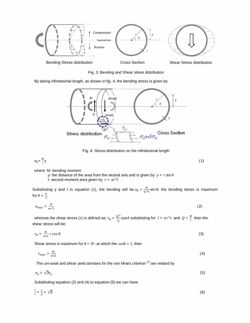
A three dimensional finite element analysis model has been created using the ABAQUS package to conduct the hysteresis behavior of circular pipe damper. A meshed analysis model of circular pipe damper is shown in Fig, 6. The end plates are modeled as a rigid body. Material nonlinearity was included in the finite element model by specifying a stress–strain curve in terms of the true stress and plastic strain. The engineering stresses and strains obtained from the coupon tests were converted into true stresses and strains for this purpose. Both solid and shell element model have been tried in order to choose the suitable element to simulate the hysteresis behavior. 3-D solid continuum elements are found to be more efficient in modeling CPD. The structural steel components are modeled as an elastic–plastic material. With elastic and plastic options, the yield and ultimate tensile strength obtained firstly from the results of the coupon tests and then converted into the true stress and plastic strain with appropriate input format for ABAQUS. In the plastic range the important behavior of structural steel to be considered is strain hardening behavior of material. Thus, a bilinear isotropic hardening model was used for LYP225 and combined hardening model was implemented for conventional steel. Different mesh sizes have been examined as well to determine a reasonable mesh that provides both accurate results with less computational time. The exam results show that, if the mesh is too coarse, a convergence problem will be caused as the contact element was used between the column flange and the endplate surface. However, if the mesh is too fine, the computational time is excessive. The mesh selected is shown in Fig. 6 for the CPD with continuous hexahedral solid elements suitable for linear and nonlinear stress/displacement analysis. The type of element is called C3D8R by ABAQUS (Fig 6b). For better accuracy the ends of the model is meshed differently relative to the body. Each ends of the components are created a more refined mesh as that is where most stresses are concentrated and is the area exposed to direct compression and tension forces. The model created has 2184elements.
Constraint and Loading Condition In the interaction, the reference point is created to control the constraint and loading condition at the center of both end plates. The boundary condition and method of loading adopted in the finite element analysis followed closely those used in the tests. The lower end plate (at reference point) is constraint both translation and rotation in all direction. The upper end plate (at reference point) allows translation only in the direction of loading and all the other direction is constraint. There are two ways of applying loads: the constant stress loading and the constant strain loading. In this study, the constant strain loading is used; that the loading is applied by controlling the displacement. Fig. 8 shows the displacement protocol used for both experiment and analysis.
(a) (b) C8D8R
Fig. 6. (a) 3-D FE- mesh of circular pipe damper, (b) C8D8R element
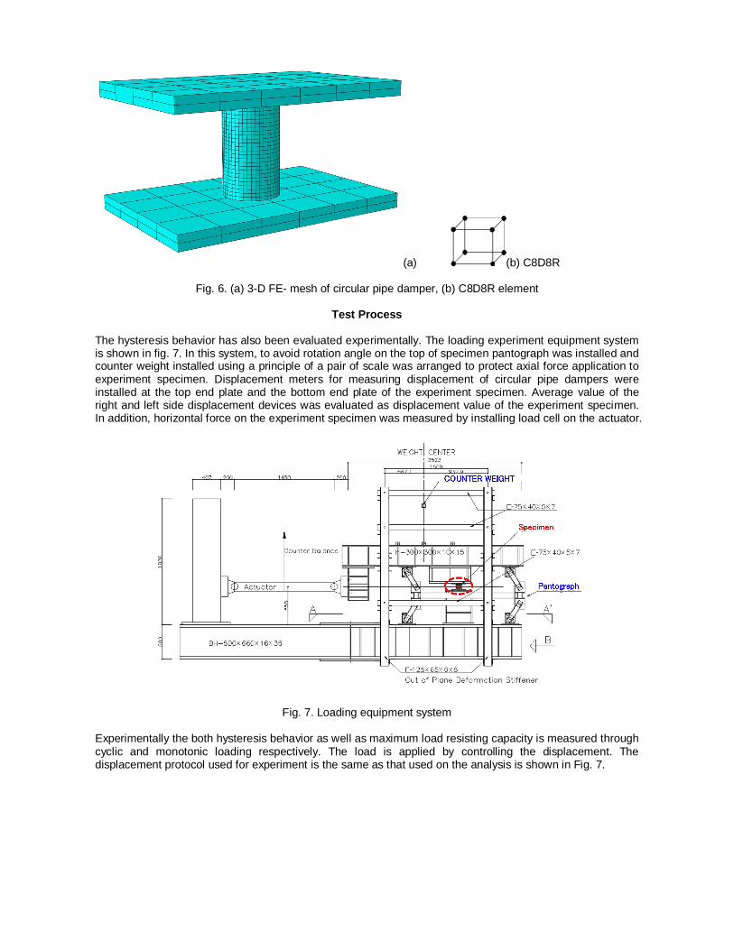
Test Process The hysteresis behavior has also been evaluated experimentally. The loading experiment equipment system is shown in fig. 7. In this system, to avoid rotation angle on the top of specimen pantograph was installed and counter weight installed using a principle of a pair of scale was arranged to protect axial force application to experiment specimen. Displacement meters for measuring displacement of circular pipe dampers were installed at the top end plate and the bottom end plate of the experiment specimen. Average value of the right and left side displacement devices was evaluated as displacement value of the experiment specimen. In addition, horizontal force on the experiment specimen was measured by installing load cell on the actuator.
Fig. 7. Loading equipment system Experimentally the both hysteresis behavior as well as maximum load resisting capacity is measured through cyclic and monotonic loading respectively. The load is applied by controlling the displacement. The displacement protocol used for experiment is the same as that used on the analysis is shown in Fig. 7.
Fig. 8 Displacement protocol
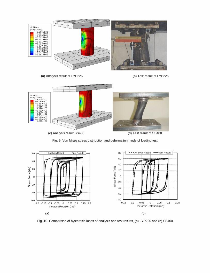
Result and Discussion After carrying out both analytical and loading test the relationship between shear force and inelastic rotation is compared. Fig. 9 (a and b) presents the hysteresis loops comparison of analysis and loading test result for LYP225 and conventional steel (SS400) respectively. In the plotted graph, the black solid line represents experimental result and the dotted line shows the analysis result. The experimental result has larger strength in the last few cycle and smaller strength in the initial yield strength relative to numerical result in the LYP225 hysteresis loops. As it has been reported above the ductility capacity of low yield point steel is high and so that high cyclic load resistance capacity. Fig 9 presents the deformation shape of experimental and equivalent stress distribution of analysis result. The failure of the CPD is predicted by the failure index defined by the triaxiality of the stress field and the accumulated plastic strain in tension and compression. The objective function is the dissipated energy before failure of the damper. The ductility capacity of the damper is defined using failure index as follows. The variables, which are functions of pseudo-time, such as stresses and strains are evaluated at integrated maximum possible point. Let εp(t) denote the equivalent plastic strain defined as
휀 (푡) = 휀̇ (휏)휀̇ (휏)푑휏(7)
where ε (t) is the plastic strain tensor, ( ̇) is the derivative with respect to time, and the summation convention is used. The equivalent plastic strain represents amount of plastic deformation in material level, and is evaluated at each integration point. Many fracture criteria have been presented using εp(t). In the following, the argument t is omitted for brevity. We use an extended version of the SMCS criterion that was developed for simulating ductile fracture of metals due to void growth. The critical plastic strain εcr is first defined as
휀 = 훼푒푥푝 − 1.5휎휎 (8)
where σm is the mean stress, and σe is the von Mises equivalent stress given by eqs. (9 and 10) respectively. The parameter α is dependent on material. Eq. (8) indicates that the critical plastic strain for ductile fracture depends on the stress triaxiality σm/σe. Then the failure index for monotonic loading is defined as in eq. (11).
σ =휎 + 휎 + 휎
3 (9)
σ =12
{(휎 − 휎 ) + (휎 − 휎 ) + (휎 − 휎 ) }(10)
퐼 =
휀휀 (11)
The material is assumed to fracture when If reaches 1.0. Fig. 9 shows failure index versus cycle relationship of analysis result. From the fig. the LYP fractured at the 11cycle and SS400 was fractured at the cycle of 9.
-0.2-0.15
-0.1-0.05
00.050.1
0.150.2
0 2 4 6 8 10 12 14
Rota
tion
(rad
)
Cycle
(a) Analysis result of LYP225 (b) Test result of LYP225
(c) Analysis result SS400 (d) Test result of SS400
Fig. 9. Von Mises stress distribution and deformation mode of loading test
(a) (b)
Fig. 10. Comparison of hysteresis loops of analysis and test results, (a) LYP225 and (b) SS400
-60
-40
-20
0
20
40
60
-0.2 -0.15 -0.1 -0.05 0 0.05 0.1 0.15 0.2
She
ar F
orce
(kN
)
Inelastic Rotation (rad)
Analysis Result Test Result
-80
-60
-40
-20
0
20
40
60
80
-0.15 -0.1 -0.05 0 0.05 0.1 0.15
She
ar F
orce
(kN
)
Inelastic Rotation (rad)
Analysis Result Test Result
Fig. 11. Failure Index of FE-analysis model Fig. 12. Comparison of cumulative energy
From the hysteresis loops it is possible to calculate the cumulative energy absorbed, fig. 12 presents the comparison of the loading test and analysis result of LYP and conventional steel.
Conclusion The hysteresis behavior of circular pipe damper was evaluated with both experimental and analytical approaches after identifying the effective size found to be aspect ratio of√3. Unlike SS400, that governs combined isotropic and kinematic strain hardening, low yield point steel behaves isotropic strain hardening behavior. Thus, both FE-analysis and test result of hysteresis loops shows an expansion in each cycle before failure. The cyclic load resistance of LYP is good relative to SS400 as it fails at 11th cycle but SS400 steel fails at 9th cycle. Though the resisting capacity of LYP is less that SS400, the cumulative energy dissipated by LYP steel circular pipe damper is higher because LYP is more ductile compared to conventional steel. Therefore, low yield point steel is good material to be used as hysteresis of the material damper as a source of seismic energy dissipating device.
Acknowledgements This work was financially supported by Basic Science Research Program through the National Research Foundation of Korea (NRF) funded by the Ministry of Education, Science and Technology (No.2012-0008837, No.2012-0004069)
References
N. Yasui, 2010, "Cyclic Loading test using plastic deformation for evaluation of performance of cold-formed circular steel pipe columns," Journal of Japanese society of steel construction, Vol.17, No.68, pp1~12.
D. Y. Abebe, J. H. Choi, 2012. Structural Performance Evaluation of Circular Pipe Steel Hysteresis Damper,
Proceeding of IUMRS-ICA2012.
C. S. Oh, N. H. Kim, Y. J. Kim, J. H. Baek, Y. P. Kim, W. S. Kim, 2011, ‘A finite element ductile failure simulation method using stress-modified fracture strain model’ Engineering Fracture Mechanics 78 (2011) 124–137
D. Y. Abebe, 2012. A Study on Nonlinear Inelastic Buckling and Response Behavior of Steel Members
Under Axial Loading. Master Thesis, Chosun University, Gwangju, Korea.
ABAQUS ver. 6.10-1, 2011. User manual and documentation Dassault Systems,