A simple theory and some experimental observations are presented of the transient withdrawal of rotating, stratified fluid in a field of gravity. The problem is confined to axisymmetric geometry and negligible viscosity. It is predicted that the withdrawal initially proceeds like non-rotating selective withdrawal, but at a time equal to 3~/3/2f there is a transition to a rotation-dominated selective withdrawal process which requires that fluid come from distances above and/or below the inlet given by the time-dependent formula (fQt/2~roN) 1/2. Experimental observations are given which are in approximate agreement with the predictions.
1. INTRODUCTION
Selective withdrawal, the flow of stratified fluid into a sink, has received a considerable amount of s tudy over the last two decades, but little a t tent ion has been paid to such problems when the fluid is rotating. In many problems in meteorology, oceanography, planetary physics and astrophysics, and doubtless engineering, it would be useful to have a technique available for the estimation of uplift and/or downlif t of surfaces of constant density into a sink when the entire system is rotating.
Here we will develop a rather simple me thod for estimating the maximum height above or below a sink from which stratified fluid can descend or rise at it is sucked in. It will be assumed that the fluid is linearly stratified and motionless at t ime t = 0. Gravity is downward and the entire system is rotating with angular velocity ~ = f / 2 . After t = 0 the sink, which will be uniformly distr ibuted around a circle of radius r0, will be turned on with total mass flux Q. The sink may be along a wall which faces inward, toward the central axis of the sink; or it may be along a wall which faces outward, away f rom the central axis of the sink. Fluid may rise f rom below the sink upward, or descend from above the sink downward. For clarity we will discuss only the upper half-plane, so fluid only comes down to the sink. We
will then test the estimate against some measurements in a laboratory experiment.
This small initial effort is most analogous to the early works by Yih on selective withdrawal and the experiments by Debbler which are described by Yih (1980) and Turner (1973). Recent works which concern viscous and transient effects and detailed velocity profiles are far beyond the scope of the present work.
The basis for the theory lies in the analysis by Whitehead and Porter (1977) (WP), who predicted the upstream height at some radius of origin for the axisymmetric withdrawal of a layer of homogeneous fluid in a rotating frame which lies under a stagnant, deep second fluid. An explicit formula was obtained which related mass flux Q with the upstream height hi at the radius of origin r l , the radius of the sink r0, the density difference between the fluid being removed and the stagnant layer overhead Ap, the Coriolis param- eter (two times angular rate of rotation) f, and the force of gravity g. This formula is
Q=2T(ro(2)3/2(g,)l/2ih1_ f2 ( _r2)213/2 8g' \ro ~o" d (1)
(WP, eq. 14 with g' < < g and vl = 0), where g' = gAp/p . If one could develop a method to predict the appropriate rl and g' for a continuously stratified fluid, (1) might be useful for predicting hi , which one would normally consider to be a height of selective withdrawal. Here it will be assumed that Q is constant for t > 0 and that r l , h I and g' vary with time. Before proceed- ing to develop the appropriate r~ and g' and discussing what h~ is equivalent to in the stratified fluid, it is useful to review the derivation of (1). The steady Navier--Stokes equations in a cylindrical coordinate system with friction ignored, for fluid of density p which lies under a fluid of density p -- Ap, are
~r(ruh ) = 0
~u _ v_Z = _ g , ~ ( f 2 r e ~ --fv + U ~r r -~r h - - ~ - /
i ) U\~r +-+r f =0
Since u # 0, velocity in an angular direction can be determined by integrat- ing the term in parentheses in the third equation to give
fr~ fro V- 2to 2
where it is assumed that v at rl is zero. Solution (2) can be used in combi-
(2)
125
nation with the other two equations to derive
Q2 g'h 3 - - g ' H h 2 + 87r2r~ = 0 (3)
(eq. 8 in WP with g' < < g and v = 0 at rl) , Here, H is a spatially varying Bernoulli head
H = h 1 f2 (r 2 - r 2 ) 2 (4) 8g'r e
Equation 3 varies from its counterparts in non-rotating hydraulic problems principally in that the "head" H varies with position. Henceforth this will be called a "virtual head". Such an effect was pointed out by Sambuco and Whitehead {1976). Although eq. 3 contains all the dynamics necessary to predict h as a function of r and Q, the equations allow many values to exist, depending upon the value of h at r l . There is, however, a miminum value of h at rl which allows the fluid to flow to r0, below which fluid runs out of virtual head before it reaches ro, and this (unique) value can be determined in many ways. One of the most convenient is to say that
Or ah 0 a t r r0 (5a)
although this strictly violates one of the assumptions used in deriving the starting equation (but only in a small region close to r0). An equivalent one is that the Froude number be equal to one at r0, i.e.
Q = ( g ' h o ) 1/2 (5b) 27rr0h0
Either (5a) or (5b) will lead to (1) when applied to (3). What does this two-layer problem have in common with selective with-
drawal of a stratified fluid? It appears that it has the two most important elements:
(1) F = 1 at the inlet {density surfaces are sucked up and down to the inlet in response to Bernoulli's law).
(2) An advected inertia is balanced by pressure in the fluid by virtue of a law like Bernoulli's law (at least for inertial selective withdrawal, which is being considered here).
It thus seemed reasonable to hope tha t (1), with suitable interpretations of g' and rl , could lead to a useful method for estimating hi (suitably inter- preted) as a function of flux Q and rotat ion rate. We will proceed under that assumption and test the result against experiment. It will be shown in Appendix 1 that the solutions so generated do not generate large temporal acceleration forces, and in Appendix 2 large viscous forces for water.
There are, of course, a number of pitfalls in applying the above equations
126
to a laboratory experiment with continuous stratification. Obviously there is really no unique value of rl and hi for the continuously stratified case. We interpret rl as being that radius which the fluid at the sink at t ime t had at the beginning of the experiment. In reality, fluids may come from different radii, so this may be a very poor assumption. It does, however, lead to a sim- ple relation between h~ and r l , since fluid which originated at r~ will reach the inlet when a volume of size 7rhl(r 2 -- r 2) has been removed, so that
Q t = - r ,)hl Although this is a Lagrangian argument to a problem which has been posed with Eulerian dynamics, we believe this may be quite correct dynamically for the following reason. The principal function of rl in (1) is to create velocity in the angular direction at the inlet as given by (2) which modifies the virtual head (4). Since the angular velocity depends on conservation of angular momentum, (2) is also true in a Lagrangian sense on any ring of fluid.
To solve for Ap in (1} the relation 1 ap
Ap - 2 az hi
will be used. Such a relation is so widely used to model a stratified fluid that little need be said. With these assumptions, the parameters r~ and Ap can be eliminated in (1) and one predicts
1~/2 Q : 47rr0(~) Nh 2 [ 1 - - [ fQt )21s/2 \ 2 7 t r e k 2 (6)
where N - [ (g/p)a p/a z ] 1 ! a is the Brunt--V~iis~il~i frequency. Before discussion of the features of the solution and comparison of the
prediction with experimental observations, a few remarks will be made about the dynamics which have been included in the problem. When fluid is with- drawn from a reservoir containing stratified fluid, surfaces of constant density are observed to be uplifted from below the level of the sink and depressed from above the level of the sink due to a lowering of pressure at the sink. Here we have simply arrived at a form of Bernouilli's law that is used to estimate a height change that surfaces of constant density must undergo to generate that pressure. There is a balance between velocity head at r0 and hydrostat ic head. The concept of critical control is only necessary in order to give an estimate of what that maximum possible withdrawal will be. The problem of solving for rl is important only because the swirl velocity v is very strongly dependent on rl .
As time progresses from zero, prediction (6) is as follows. Initially the term within the s~tuare brackets will be close to one so
i 1'' hi ~ 271/4 \ ~ ] , t < 271/2/2f (7)
127
Naturally, this relation holds for a fluid wi thout ro ta t ion as well. For instance, it differs f rom the non-rotat ing Froude number criterion {which is a predic- t ion for a steady problem) hi = (Q/2roN) 112 (Yih, 1980; Brooks and Koh, 1969, eqs. l l b , c) by less than 10%. After
t = 271/2/2f, {8)
the term in the square brackets in eq. 6 would become negative unless height becomes close to the value
hi ~ \2~roN ! , t :> 2711212f {9)
In this limit the swirl velocity v becomes greater than the radial velocity, and the geostrophic and cyclostrophic balance at the sink radius determines the height of selective withdrawal.
The fact that this formulat ion agrees with that of Brooks and Koh {1969) in the absence of rotat ion lends some validity to the many assumptions which have been used. As a fur ther test, the predictions were tested against experiment .
2. AN E X P E R I M E N T A L T E S T
The objective of the experiments was to obtain quantitat ive data on the selective withdrawal height above and below axisymmetric inlets. Two experimental containers were used. The first was a rectangular plexiglass container 35 cm wide, 35 cm broad and 30 cm deep, moun ted on a 1 m diameter turnable. On the bo t tom, a copper manifold was embedded in 6 cm of crushed rock. The manifold was connected, by flexible tubing and a swivel connector , to two tanks which were set up to supply water whose sali- nity increased uniformly in t ime by the Oster method , as sketched in Fig. 1. The second tank was also square with an internal cylindrical false wall 1 m in diameter. All else, except the volume of the filling tanks, was the same. In each exper iment the container was moun ted on a carefully levelled 1 m turnt- able which was set to uniform rota t ion and slowly filled f rom below via the manifold so that after 2 h it was filled with uniformly stratified water with a density gradient (1/po)ap/az of 0.0021 + 0.0002 cm -~. The water exhibited a drif t with respect to rigid ro ta t ion of less than 0.01 tad s -~. Salinity was measured with an optical re f rac tometer at every 2 cm of depth.
In the first runs a pipe with an outside diameter of 0.95 cm and inside diameter of 0.70 cm was suspended vertically halfway down into the water. The small container was used since the gyre formed around the withdrawal pipe at the center of the tank. The withdrawal pipe was filled with fresh water and was at tached to a siphon hose and a pipette. By adjusting the height of the spout of the pipet te with respect to the free surface of the water in:the test tank, a steady volume flux of 0.2 cm a s -1 was obtained.
128
m _ ~ F
!
Fig. 1. Sketch of the laboratory apparatus and the method of generating a stratified fluid by the Oster method. The broken lines correspond to the water surfaces after the tanks have been filled.
After the sink was turned on, pellets of potassium permanganate were dropped into the tank along a straight line stretching from the withdrawal tube to one side of the tank. The pellets rapidly sank and left a vertical dyed column. After these had been somewhat distorted by lateral flows, photographs were taken of them against a white background with a 35 mm camera equipped with a 135 mm lens. The purpose of the telephoto type of lens was to minimize apparent optical distortion to the light rays which reached the camera by observing an image formed by rays which left the tank at an angle which was almost normal to the wall of the tank. Periodically, new pellets were introduced and pictures were subsequently taken. The distorted columns give a clear measure of the velocity flow structure.
Figure 2 shows a typical photograph of vertical columns which have been distorted by the flow. Of course, the flow field is really smooth rather than discrete, and our intention is to find the vertical extent for most of the withdrawal, not a height where there is a clear jump in water properties. We presume that the height of large flow corresponds to the height of selective withdrawal. Therefore, the heights which will be reported here were heights
129
Fig. 2. Photograph of dye columns in an experiment which has been running for some time. The old columns have been swept around by rather deep, sluggish gyres which lie above and below the dynamic withdrawal region. New columns, on the right, display a distortion which marks the region of true selective withdrawal, which is characterized by radial as well as angular flow.
of 90 to 95% o f the d isp lacement . Figure 2 and vir tual ly all the o t h e r p h o to - graphs give some evidence to suppo r t this conclusiQn. T h e vert ical lines on the lef t and r ight show evidence o f the region o f ve loc i ty in the angular direc- t ion , while the older , r e m n a n t d y e lines display a clearer layer near the level of the inlet p re sumab ly because clear wa te r has co me in f rom fu r t h e r out .
Clearly, the f low varies wi th dis tance away f rom the sink and the re is no single d e p t h o f selective wi thdrawal . F o r t u n a t e l y , wi th a small ex i t pipe m o s t o f the vert ical excurs ions of the wa te r t o o k place near the sink, where a p r o n o u n c e d vo r t e x deve loped . The re was lit t le change in d ep t h away f ro m the sink. Thus we r e p o r t here those measu remen t s t ak en over a var ie ty o f radii, wi th no bias e xc ep t t ha t the radius was always a few cen t imete rs , b u t n o t large enough to show no shear. We also r epo r t on ly m ea su rem e n t s where rl is p red ic ted to be less t han the size o f the tank.
As a no t e o f cau t ion to those who might t ry such a m e a s u r e m e n t techni- que, the old pel let co lumns were s lowly swept by large, sluggish gyres {possibly T a y l o r co lumns) above and be low the region where the currents were intense, and one could easily be deceived in to th ink ing tha t the region including
130
. . . . . . . . , . . . . . > ~ , '~ 40
0°¢~ . ~ % . Y - 0 ,
. 10 x o °
" ~ : 0 ~ f ~ 1 I I I I I I I I I I I I I I I 2 i0 ! O0 1000
t, seconds
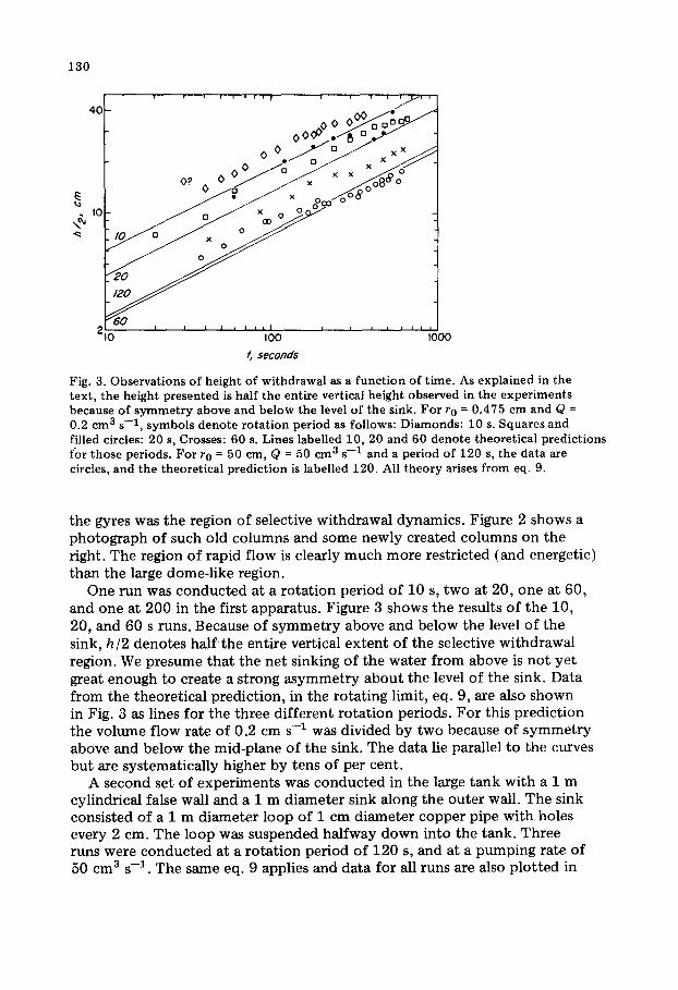
Fig. 3. Observa t ions o f height o f wi thdrawal as a f unc t i on of t ime. As expla ined in the tex t , the height p resen ted is half the ent i re vertical height observed in the expe r imen t s because of s y m m e t r y above and be low the level o f the sink. Fo r r 0 = 0.475 cm and Q = 0.2 cm 3 s - 1 , symbo l s de no t e ro t a t i on per iod as fol lows: Diamonds : 10 s. Squares and filled circles: 20 s, Crosses: 60 s. Lines labelled 10, 20 and 60 deno te theore t ica l p red ic t ions for those periods. For r 0 = 50 cm, Q = 50 cm 3 s - 1 and a per iod of 120 s, the data are circles, and the theore t ica l p red ic t ion is labelled 120. All t heo ry arises f rom eq. 9.
the gyres was the region of selective withdrawal dynamics. Figure 2 shows a photograph of such old columns and some newly created columns on the right. The region of rapid flow is clearly much more restricted (and energetic) than the large dome-like region.
One run was conducted at a rotat ion period of 10 s, two at 20, one at 60, and one at 200 in the first apparatus. Figure 3 shows the results of the 10, 20, and 60 s runs. Because of symmet ry above and below the level of the sink, hi2 denotes half ' the entire vertical ex tent of the selective withdrawal region. We presume that the net sinking of the water from above is not ye t great enough to create a strong asymmetry about the level of the sink. Data from the theoretical prediction, in the rotating limit, eq. 9, are also shown in Fig. 3 as lines for the three different rotat ion periods. For this prediction the volume flow rate of 0.2 cm s -1 was divided by two because of symmet ry above and below the mid-plane of the sink. The data lie parallel to the curves but are systematically higher by tens of per cent.
A second set of experiments was conducted in the large tank with a 1 m cylindrical false wall and a 1 m diameter sink along the outer wall. The sink consisted of a 1 m diameter loop of 1 cm diameter copper pipe with holes every 2 cm. The loop was suspended halfway down into the tank. Three runs were conducted at a rota t ion period of 120 s, and at a pumping rate of 50 cm 3 s -1. The same eq. 9 applies and data for all runs are also plot ted in
131
Fig. 3, with a cor responding line f rom eq. 9. Again, because of s y m m e t r y , half the height o f selective wi thdrawal is given, and half the vo lumet r ic pumpin g rate is used in the calculat ion. In this case the shear zone be tween selective wi thdrawal was easier to ident i fy in real t ime than in the pho tog raphs and measurements are believed to be good to _+15%.
A third expe r imen t was done in the large tank. The sink was the small central pipe which had been previously used in the small tank. The object ive was to see whe the r the t ransi t ion f rom non- ro ta t ing to ro ta t ing f low could be observed. In order to have suff icient t ime to observe the d is tor t ion o f the vertical dye co lumns it was necessary to make ro ta t ion as slow as possible; in this case a per iod of 355 s was set for the turntable . I t was also believed necessary to have sufficient f lux ou t o f the sink to overshadow the ef fec t o f viscosi ty; the vo lume flux o f 2 .54 cm 3 s - 1 was believed to be suff icient for this.
The dye co lumns were p h o t o g r a p h e d every 20 s. Results are shown in Fig. 4. Fresh pellets were re - in t roduced af ter every second or th i rd p h o t o g r a p h ; a d a t u m based on a new c o l u m n is d e n o t e d by an arrow. The da ta lie parallel bu t above the tw o predic ted a s y m p t o t e s f r o m eqs. 7 and 9. The quali tat ive agreement is qui te good; however it is no t ent i re ly clear whe the r there are enough data to show clear agreement with the non- ro ta t ing case. Measure- ments o f the pho tog raphs with an opt ical m i c r o m e t e r wi th errors smaller
3.C
2.0
1.0
i i i I i i i i i i
I I I I I I I I I I I i I J i
2 0 100 5 0 0
f, seconds
Fig. 4. Observations of the height of withdrawal as a function of time for r 0 = 0.475 cm, Q = 2.54 cm 3 s -1 , and a period of rotation of 355 s. The non-rotating prediction of height, eq. 7, and the rotating prediction of height, eq. 9, are shown as straight lines. Because of symmetry above and below Lhe midplane of the tank the mass flux Q must be divided by two and the observed height h I is half the observed vertical extent of withdrawal. Arrows denote where data were based upon a newly introduced column of potassium permanganate.
132
than the equivalent of +0.1 cm were made twice with extra caution to ensure that the data were as accurate as possible.
Thus it appears that there is some experimental evidence that the rather simple formula given by eq. 6 would give a useful estimate of selective withdrawal into an axisymmetric sink. Nowhere has the assumption been made that rl is bigger or smaller than to, so fluid flowing outward toward a cylindrical sink has the same features as fluid flowing inward. Also, in the limit of ro being much bigger than r 1 -- r0, the problem approximates flow into a line sink in a Cartesian coordinate system.
A result which is simpler than anticipated is that frame rotat ion always becomes impor tant at a t ime equal to 3~/3/2f which, in a geophysical context , would be equal to 0.21/sin 0 {time units are days) where 0 is latitude. This is considerably earlier than one normally expects to see the effects of rota- tion being set up and raises the possibility of whether considerable swirl from the earth's ro ta t ion may be generated near axisymmetric or line sinks in nature such as cumulus clouds ( turbulent plumes act as sinks to adjacent fluid), deep ocean convection plumes, the proposed ocean thermal energy conversion (OTEC) power plants and sea breezes.
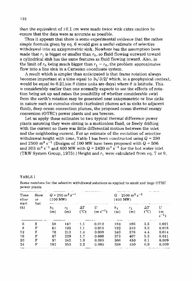
Let us apply these estimates to two typical thermal difference power plants assuming they were sitting in a motionless fluid, or freely drifting With the current so there was little differential mot ion between the inlet and the neighboring current. For an estimate of the evolution of selective withdrawal height with time, Table I has been constructed using Q = 250 and 2500 m 3 s -1 (Designs of 100 MW have been proposed with Q = 506 and 303 m 3 s -1 and 400 MW with Q = 2420 m 3 s -1 for the hot water inlet (TRW System Group, 1975).) Height and rl were calculated from eq. 7 or 9,
TABLE I
Some n umb er s for the selective wi thdrawal so lu t ions as appl ied to small and large OTEC power plants
Time Slow Q = 250 m 3 s - 1 Q = 2500 m 3 s - 1 af ter or (100 MW) (400 MW) start fast (h) h 1 r I AT U h 1 r I AT U
(m) (m) (°C) (m s - 1 ) (m) (m) (°C) (m s - 1 )
6 S 58 167 1.1 0.012 183 296 3.3 0.021 8 F 61 193 1.1 0.010 192 343 3.3 0.018
12 F 76 213 1.4 0.008 240 378 4.4 0.014 16 F 87 229 1.7 0.006 275 407 5.3 0.011 20 F 97 242 1.9 0.005 306 430 6.1 0.009 24 F 107 253 2.2 0.005 338 450 6.9 0.009
133
and the conservation of mass respectively. Tempera ture degradation was calculated assuming that water for the warm water inlet was sucked up into the inlet f rom an average depth of h l / 2 below the top surface, through the use of an OTEC design bathythermal profile which has been used as a " typ ica l " ocean tempera ture profile for engineering purposes (TRW System Group, 1975, pp. 3--6). Lastly, the ocean current necessary to stop growth at the listed values of hi and rl by replacing the mass flux in an area of 2h l r I is given.
The table shows that there may be some degradation of the inlet tem- perature due to selective withdrawal. A glance at typical current meter records, such as are shown in the MODE atlas (Lee and Wunsch, 1977) will show that ocean currents are of ten in excess of the velocities given in Table I as being necessary to supply the water to the inlet. We presume that when this happens the growth of the withdrawal region as predicted by the theory will stop. However, there are occasional t ime intervals of many days when currents were smaller than 1 or 2 cm s -1 , during which the theory would predict that considerable rotat ional effects would develop.
Probably the predictions for withdrawal height are biased toward numbers that are larger than a real OTEC powerplant would experience. Such oceanic processes as internal waves, vertical shear, and friction in the surface mixed layer will all counteract the mechanism presented here. However, such processes, although they might occur rarely, may degrade the ou tpu t of the plant or create unique torques on the plant which are best anticipated and accounted for.
ACKNOWLEDGMENTS
Support was received from the Oceanography Section, National Science Foundat ion , under Grant OCE78-09448. We thank Rober t Frazel for fabricating the laboratory tank, doing the photography, and assisting in the experiments. Woods Hole Oceanographic Inst i tut ion Contr ibut ion Number 4367.
APPENDIX 1. LIMITS OF VALIDITY OF THE STEADY APPROXIMATION
For the spatial acceleration terms to be smaller than other terms, the inequality
u/ l > 1 / t
must hold, where l is some horizontal length scale; I will be set equal to rl -- r0, and t ime t will be determined. Rearranging,
lutL > rl --ro
rl is eliminated by the use of
r~ - - r2o = Q t / ~ h 1
(A1)
(A2)
134
Equation A2 can be substituted into (A1) which can be rearranged to the form
u2t + 2uro > Q/Trh I (A3)
To calculate u, note that the largest u occurs at ro, and is
u = Q/2~roh(ro)
Using the definition of H, Ap = h 1 (Op/Oz)
3Q u = 4~ro [h I -- f2(r2 o -- r21 )2/4N2hlr~ ] (A4)
Since the non-rotating balance is established first, let eq. 7 be used first to eliminate hi
hi = (Q/41rroN)l/227114 (A5)
Combining (A3) and (A4) with f = 0 and (A5), one obtains
9(QN)112t/8(27)114~rl/2r312 + 3/2 > 1
The inequality is always satisfied but becomes large when
t > 4(~ro3) 1/2/3114(QN)112 (A6)
Depending upon the particular physical situation, this may be a long or short time compared to the time x/27/2f when there is a transition to a rotating limit. For rapid rotat ion the velocity in an angular direction is important , SO
vt > rl -- ro
From (2)
f r2 f r o t t > r l _ r o - ro 2 /
Rearranging
f t ( r l + r o ~ > o (A7) 2 \ ro !
Since the rotating limit does not become valid until f t > x/27/2, the quasi- steady limit always appears to be valid for the rotating problem.
135
APPENDIX 2. ESTIMATE OF THE EFFECT OF VISCOSITY
If t is the t ime since the beginning of wi thdrawal , for viscosi ty to be im- po r t an t we wan t
twithdrawal < tviscou s = h2/V (A8)
The viscous t ime scale is h2/v, where h is the dep th o f a fluid and v is the k inemat ic viscosity. Using eq. 7 to el iminate h
t < ~/27 Q/4~roNv (A9)
For the first exper iments r epor t ed here, Q was app rox ima te ly 0.2 cm 3 s -1 , r0 was 0.35 cm, N was 1.45 s -1 , and v was 0 .01.
Equa t ion A9 predicts t ha t viscosity becomes i m p o r t a n t in 16 s. Since the balance will exhibi t a t ransi t ion to a ro ta t ing balance af ter two- t en ths o f a revolu t ion t ime, there will be a t rans i t ion to ro ta t ing f low before the viscous effect becomes established for any exper iments with ro t a t ion periods o f less than 80 s. I f the per iod is m o r e than that , a viscous balance will occur before this t ransi t ion takes place, with unpred ic t ed results.
Af te r the ro t a t i on balance is established, eq. 9 mus t be used to solve for h. This leads to
1 < fQ/2~rocNv (A10)
if viscous drag is negligible. Using the same numbers as before for Q, ro, N and v, the inequal i ty is satisfied for ro t a t ion periods o f less than 79 s; hence in this case any expe r imen t wi th a per iod under 80 s will a t ta in a ro ta t ing limit and no t subsequen t ly develop d o m i n a n t viscous effects.
REFERENCES
Brooks, N.H. and Koh, R.C.Y., 1969. Selective withdrawal from density-stratified reser- voirs. Proc. Am. Soc. Cir. Eng., HY4: 1369--1400.
Lee, V. and Wunsch, C. (Editors), 1977. Atlas of the Mid-Ocean Dynamics Experiment. POLYMODE Office, Massachusetts Institute of Technology, Cambridge, MA, 274 pp. (unpublished report).
Sambuco, E. and Whitehead, J.A., 1976. Hydraulic control by a wide weir in a rotating fluid. J. Fluid Mech., 73: 521--528.
TRW System Group, 1975. Ocean Thermal Energy Conversion Research on an Engineer- ing Evaluation and Test Program: Executive Summary, Vol. 1, TRW System Group, 1 Space Park, Redondo Beach, CA. 201 pp.
Turner, J.S., 1973. Buoyancy Effects in Fluids. Cambridge University Press, New York, NY, 367 pp.
Whitehead, J.A. and Porter, D.L., 1977. Axisymmetric critical withdrawal of a rotating fluid. Dyn. Atmos. Oceans, 2: 1--18.
Yih, C.S., 1980. Stratified Flows. Academic Press, New York, NY, 418 pp.