D1.3: Intermediate-Results based Protocol and Algorithm Specification (Public Part) Page 1 of 48 Project Number: IST-1999-11253-TEQUILA Project Title: Traffic Engineering for Quality of Service in the Internet, at Large Scale D1.3: Intermediate-Results based Protocol and Algorithm Specification (Public Part) CEC Deliverable No.: 103/IMEC/b1 Deliverable Type: Report Deliverable Nature: Public Contractual date: 30 th July 2001 Actual date: 30 th October 2001 Editor: Pim Van Heuven Contributors: Alcatel: Danny Goderis, S. Van den Bosch, Yves T'Joens Algosystems: Panos Georgatsos, Leonidas Georgiadis FT-R&D: Christian Jacquenet IMEC: Steven Van den Berghe, Pim Van Heuven NTUA: Eleni Mykoniati Global Crossing (Thales): Aolghasem (Hamid) Asgari, Richard Egan UCL: David Griffin UniS: George Pavlou, C.F. Cavalcanti, Panos Trimintzios Workpackage: WP1 Abstract: This public part of D1.3 is the basis for an extended white paper describing the TEQUILA rationale for QoS delivery in IP networks. The document explains the TEQUILA approach, highlights the main innovative strenghts of the project and covers Service Management, Traffic Engineering and Monitoring and Measurement, i.e. the main systems under study within the project. Keyword List: DiffServ, QoS-Class, QoS architecture, Bandwidth Broker, Service Management, Service Negotiation and Invocation, Protocols, Admission Control, Service Mapping and Aggregation, MPLS/IP-based Traffic Engineering, Monitoring, Measurement, Active and Passive Probes. CEC Deliverable Number: 103/IMEC/b1 TEQUILA Consortium - October 2001
Transcript
D1.3: Intermediate-Results based Protocol and Algorithm Specification (Public Part) Page 1 of 48
Project Number: IST-1999-11253-TEQUILA
Project Title: Traffic Engineering for Quality of Service in the Internet, at Large Scale
D1.3: Intermediate-Results based Protocol and Algorithm Specification (Public Part)
CEC Deliverable No.: 103/IMEC/b1
Deliverable Type: Report
Deliverable Nature: Public
Contractual date: 30th July 2001
Actual date: 30th October 2001
Editor: Pim Van Heuven
Contributors: Alcatel: Danny Goderis, S. Van den Bosch, Yves T'Joens Algosystems: Panos Georgatsos, Leonidas Georgiadis FT-R&D: Christian Jacquenet IMEC: Steven Van den Berghe, Pim Van Heuven NTUA: Eleni Mykoniati Global Crossing (Thales): Aolghasem (Hamid) Asgari, Richard Egan UCL: David Griffin UniS: George Pavlou, C.F. Cavalcanti, Panos Trimintzios
Workpackage: WP1
Abstract: This public part of D1.3 is the basis for an extended white paper describing the TEQUILA rationale for QoS delivery in IP networks. The document explains the TEQUILA approach, highlights the main innovative strenghts of the project and covers Service Management, Traffic Engineering and Monitoring and Measurement, i.e. the main systems under study within the project.
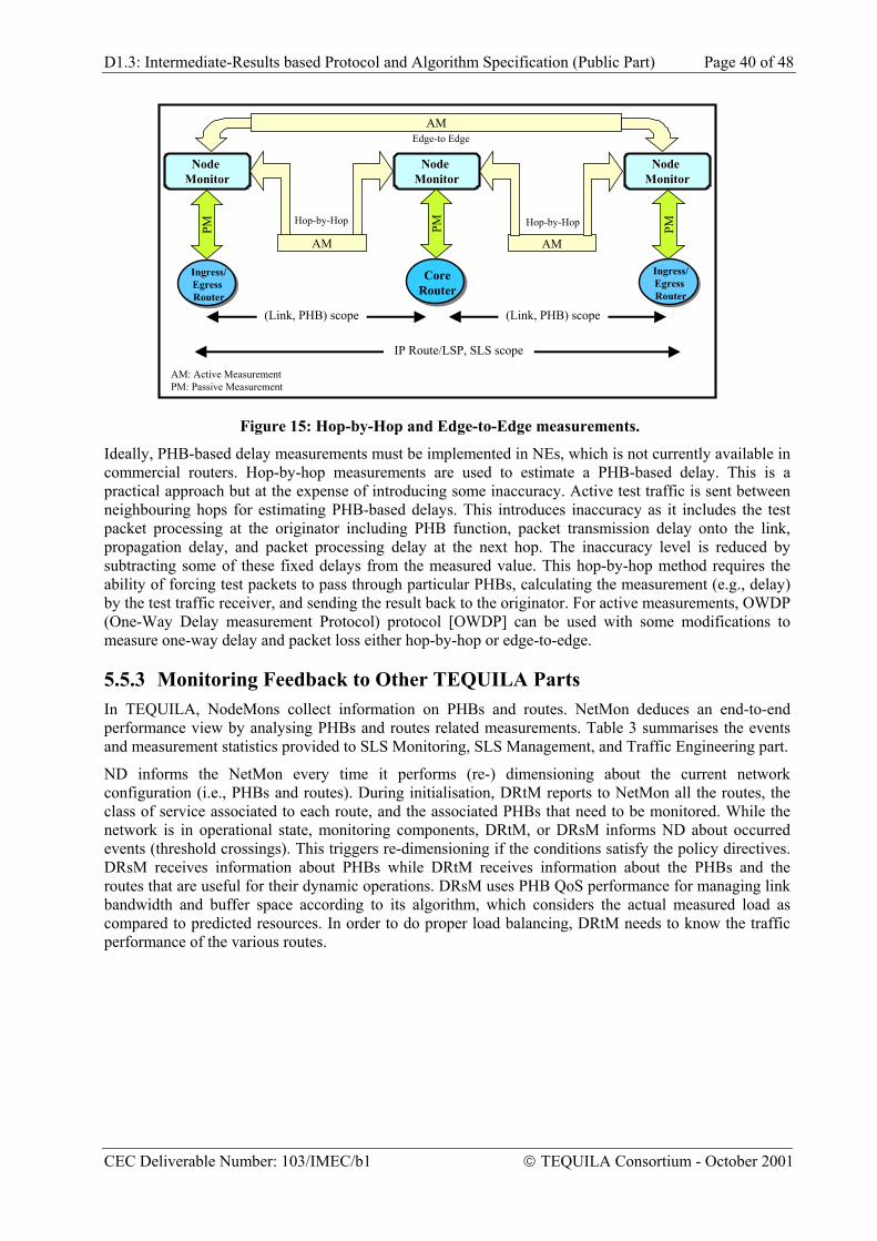
Keyword List: DiffServ, QoS-Class, QoS architecture, Bandwidth Broker, Service Management, Service Negotiation and Invocation, Protocols, Admission Control, Service Mapping and Aggregation, MPLS/IP-based Traffic Engineering, Monitoring, Measurement, Active and Passive Probes.
CEC Deliverable Number: 103/IMEC/b1 TEQUILA Consortium - October 2001
D1.3: Intermediate-Results based Protocol and Algorithm Specification (Public Part) Page 2 of 48
Project Number: IST-1999-11253-TEQUILA
Project Title: Traffic Engineering for Quality of Service in the Internet, at Large Scale
D1.3: Intermediate-Results based Protocol and Algorithm Specification (Public Part)
Editor: Pim Van Heuven
Contributors: Alcatel: Danny Goderis, S. Van den Bosch, Yves T'Joens Algosystems: Panos Georgatsos, Leonidas Georgiadis FT-R&D: Christian Jacquenet IMEC: Steven Van den Berghe, Pim Van Heuven NTUA: Eleni Mykoniati Global Crossing (Thales): Aolghasem (Hamid) Asgari, Richard Egan UCL: David Griffin UniS: George Pavlou, C.F. Cavalcanti, Panos Trimintzios
Version: Final Version
Date: 30 October 2001
Distribution: TEQUILA, CEC
Copyright by the TEQUILA Consortium
The TEQUILA Consortium consists of:
Alcatel Coordinator Belgium Algosystems S.A. Principal Contractor Greece FT-CNET Principal Contractor France IMEC Principal Contractor Belgium NTUA Principal Contractor Greece Global Crossing Principal Contractor United Kingdom UCL Principal Contractor United Kingdom TERENA Assistant Contractor The Netherlands UniS Principal Contractor United Kingdom
CEC Deliverable Number: 103/IMEC/b1 TEQUILA Consortium - October 2001
D1.3: Intermediate-Results based Protocol and Algorithm Specification (Public Part) Page 3 of 48
Executive Summary
This public part of D1.3 is a form of an extended “white paper” describing the TEQUILA rationale for QoS delivery in IP networks. The document explains the TEQUILA approach, highlights the main innovative strenghts of the project and covers Service Management, Traffic Engineering and Monitoring and Measurement, i.e. the main areas under study within the project. A TEQUILA white paper will appear in the future as a separate document.
This interim “white paper” explains the main innovative strengths of the TEQUILA project:
1. TEQUILA specifies a formal definition of a Service Level Specification (SLS) template, enabling the unambiguous definition of a value-added IP connectivity service. This enables the conveying of Quality of Service (QoS) related information for the provisioning of a guaranteed level of quality associated to the subscription of an IP service offering. This work is currently being promoted within the IETF community.
2. TEQUILA provides a holistic view for operational service and resource management and its interactions. The key aspects are the following:
- The architecture introduces a two-level approach for operational service management and negotiation, i.e. service subscription and service invocation. These two processes occur at different time scales. Subscription handles the longer term-based service requests such as VPNs, while service invocation occurs on a per-call basis, typically within the envelope of a previous subscription. The two-level approach in service management is mirrored in the resource management system. The architecture combines a longer-term off-line traffic engineering approach with a dynamic on-line handling of traffic fluctuations.
- The architecture makes a clear distinction between the customer (SLS) aware components and the resource (QoS class) aware components. The interworking is defined through the resource provisioning cycle. The Service Management system has knowledge about all customers but is agnostic for the internal network details. The Resource Management system knows about all network resources but only acts on (aggregate) QoS classes.
- Well defined interactions between the long-term, centralised off-line TE and dynamic, distributed on-line handling of traffic fluctuations for MPLS- as well as IP-based networks
The main overall result is that the architecture enables the provisioning of hard QoS guarantees to individual (multimedia) flows while still being a scalable solution. It solves the scalability problem for IP backbones by enabling a two-level approach for admission control.
3. TEQUILA proposes a scalable monitoring architecture that is able to cope with the size and the speed of the network as it evolves. This is key for providing QoS and service assurance. Monitoring of the network status plays an important role for assisting the operation of traffic engineered networks in dimensioning the network and the allocation of resources (capacity, routes, etc). The SLS monitoring architecture also provides an in-service verification of traffic and performance characteristics of the value-added IP services.
The structure of the document is as follows. Section 1 gives a short introduction to the IP QoS problem and relevant technologies. Section 2 provides a high-level overview of the TEQUILA approach and architecture. Sections 3, 4 and 5 are the main parts of the document, dealing respectively with service management, traffic engineering and monitoring and measurement.
CEC Deliverable Number: 103/IMEC/b1 TEQUILA Consortium - October 2001
D1.3: Intermediate-Results based Protocol and Algorithm Specification (Public Part) Page 4 of 48
2 THE TEQUILA APPROACH .............................................................................................................................9
2.1 RATIONALE .....................................................................................................................................................9 2.2 THE TEQUILA ARCHITECTURE .................................................................................................................10
3 SERVICE MANAGEMENT.............................................................................................................................13
3.1 INTRODUCTION .............................................................................................................................................13 3.2 A LAYERED SERVICE MODEL FOR DIFFSERV.............................................................................................13
3.2.1 Service Level Specifications ................................................................................................................14 3.2.2 Network QoS Layer..............................................................................................................................14
3.3 IP SERVICE AND RESOURCE MANAGEMENT ...............................................................................................15 3.3.1 Service Subscription ............................................................................................................................16 3.3.2 Service Invocation................................................................................................................................16 3.3.3 Traffic Forecast ...................................................................................................................................17
3.4 VOICE AND MULTIMEDIA OVER IP ILLUSTRATED .......................................................................................18 3.4.1 QoS-capable Virtual Private Networks ...............................................................................................18 3.4.2 Connecting Trunking Gateways..........................................................................................................19
3.5 A PROPOSAL FOR A SERVICE NEGOTIATION PROTOCOL: SRNP ...............................................................20 3.6 SUMMARY .....................................................................................................................................................21
4.1 INTRODUCTION .............................................................................................................................................22 4.2 A FUNCTIONAL MODEL FOR QOS.................................................................................................................22
Table 2: Formal Definition of a DiffServ QoS Class ................................................................................ 15
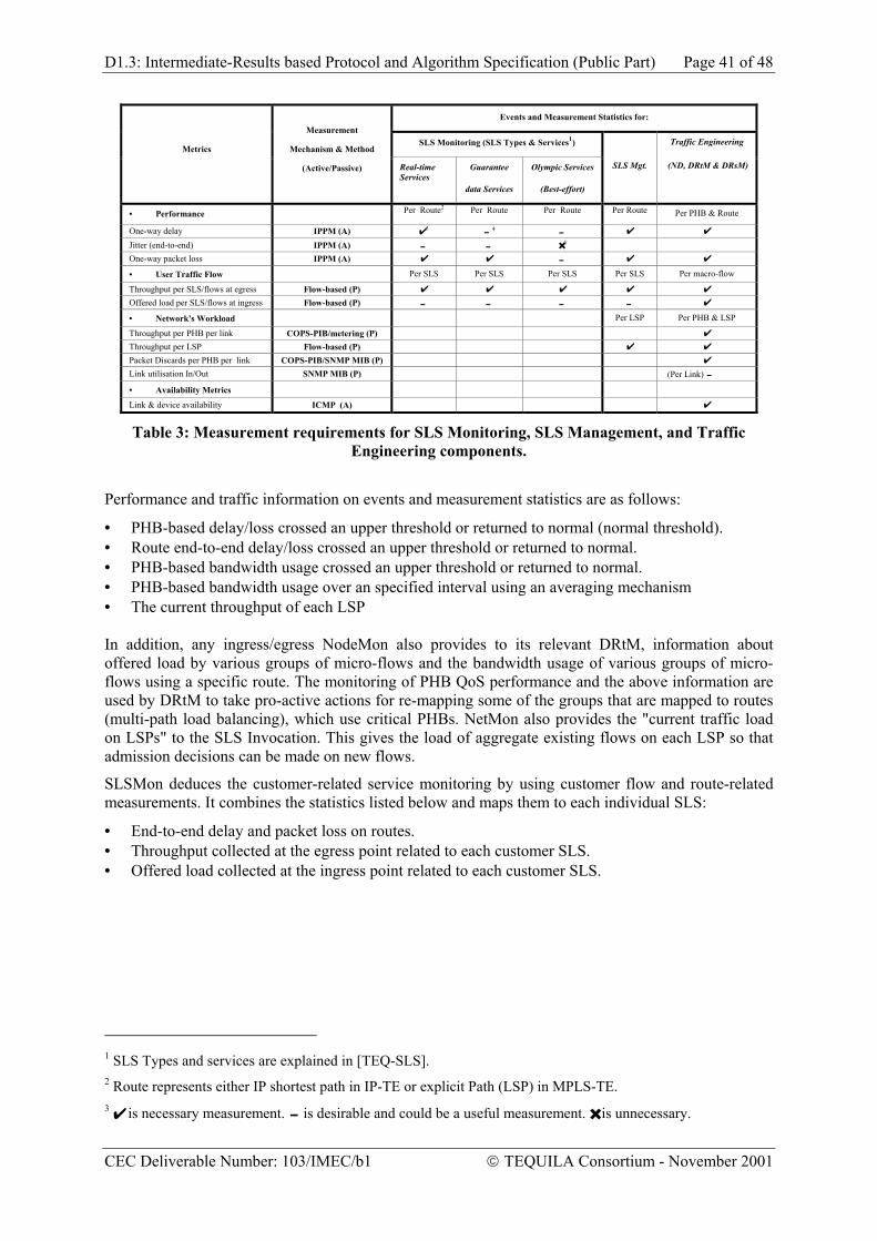
Table 3: Measurement requirements for SLS Monitoring, SLS Management, and Traffic Engineering components. ....................................................................................................................................... 41
CEC Deliverable Number: 103/IMEC/b1 TEQUILA Consortium - October 2001
D1.3: Intermediate-Results based Protocol and Algorithm Specification (Public Part) Page 7 of 48
1 INTRODUCTION Today the Internet attempts to deliver traffic as soon as possible within the limits of its abilities, but without any guarantees related to throughput, delay, inter-packet delay variation (jitter) and packet loss. So far this so-called best-effort forwarding paradigm has worked well because most IP applications are low-priority and low-bandwidth data applications with high tolerance on delay and delay-variation. Value-added IP services however, like Voice over IP (VoIP) and other multimedia applications, require stringent Quality of Service (QoS) guarantees end-to-end. Therefore, the key challenge for Next Generation Networks is to extend IP-based networks with scalable, multi-service QoS capabilities, while still providing the key advantages of IP that made the Internet possible. On these multi-service networks, operators will have to honour complex Service Level Agreements (SLAs), acknowledging different types of traffic in terms of bandwidth requirements, delay and other QoS parameters.
Within the Internet Engineering Task Force (IETF) several IP QoS technologies have been proposed. Integrated Services (IntServ) was the first proposal [RFC 1633], based on per-flow resource reservation and admission control, i.e. the Resource reSerVation (RSVP) signalling Protocol (RSVP) [RFC 2205]. IntServ is perfectly capable to provide QoS guarantees to individual applications. However, its main disadvantage is that the required per-flow state information and QoS treatment in the core IP network pose severe scalability problems. These problems led to the development of the Differentiated Services architecture [RFC 2475], which allows for flow aggregation in order to deal with the scalability issues.
Differentiated Services (DiffServ) is based on the marking of IP packets with priority information, the so-called Differentiated Services Code Point (DSCP), which is a 6-bit encoded field of the Differentiated Services (DS) byte of an IP header [RFC 2474]. DiffServ capable routers implement different packet forwarding behaviours, called Per Hop Behaviours (PHB), for distinct traffic types based on the DSCP-value in the IP packet header. This differential treatment of aggregate packet streams, i.e. on a per DSCP basis, makes DiffServ routers scalable, even at Gigabit link rates. The DiffServ technology maintains scalability in the core routers by pushing major complexity to the edges of the network and also to the management plane.
DiffServ is clearly a promising technology; however to deliver real-time multimedia services on DiffServ-based IP networks still requires a substantial amount of further research and development.
• The DiffServ architecture offers the network operator a number of elementary QoS building blocks, including the PHBs and the Traffic Conditioning Block (TCB). The way PHBs should be concatenated to emulate Virtual Leased Lines (VLLs), for example, is not part of DiffServ as it has been developed to-date.
• Although the IETF is currently defining the notion of DiffServ edge-to-edge packet behaviours, i.e. Per Domain Behaviours (PDBs) [RFC 3086], the concept of service classes and the definition of IP transport services remains vague.
• DiffServ provides service differentiation for aggregate IP packet streams by implementing different PHBs for different DSCP values. However it is unclear how QoS guarantees can be committed to e.g. individual multimedia services such as voice and video streams. Especially the required trade-off between scalability and per-multimedia-flow resource reservation and admission control is an open research issue.
Network management plays a key role in provisioning value-added IP services over DiffServ networks. Every router must be configured so that sufficient resources are available to support the SLAs that have been contractually agreed between a customer and a service provider. In addition, the overall network must be configured according to the expected traffic demand. Both individual router and overall network configuration (the latter in terms of MPLS paths and/or IP routing strategies) emanate from contracted SLSs and the associated expected traffic demand. SLSs are negotiated and invoked through service management functions. The DiffServ architecture recognises the need for combined service and network management functions through the Bandwidth Broker (BB) [RFC 2638]. Despite this, very little work has been carried out to date towards a detailed decomposition of a BB.
CEC Deliverable Number: 103/IMEC/b1 TEQUILA Consortium - October 2001
D1.3: Intermediate-Results based Protocol and Algorithm Specification (Public Part) Page 8 of 48
TEQUILA (Traffic Engineering for Quality of service in the Internet at Large) addresses key remaining research issues in the DiffServ architecture. Its primary goal is to provide an integrated management and control architecture and associated algorithms and protocols for providing end-to-end Quality of Service in DiffServ-based IP networks [TEQ-01]. This architecture can be thought as a detailed decomposition of a Bandwidth Broker although its functionality goes a lot further than that envisaged in [RFC 2638], addressing essential additional aspects for operating DiffServ networks. TEQUILA addresses both Service and Resource Management aspects while MPLS and IP-based techniques for traffic engineering are considered. A monitoring and measurement architecture is also addressed, being a key aspect for QoS delivery and service assurance.
The structure of this document is as follows.
Section 2 presents the TEQUILA approach, including a brief rationale and the proposed functional architecture for providing QoS and supporting value-added services in IP networks. It provides a holistic view of the QoS problem space.
Section 3 discusses the Service Management aspects. It proposes a layered service model for DiffServ, a clear definition of an IP transport service and a two-layered approach for service negotation and admission (control).
Section 4 proposes a service-driven traffic engineering approach for both MPLS and IP-based networks
Section 5 outlines the key role of monitoring and measurement techniques for providing QoS and service assurance.
CEC Deliverable Number: 103/IMEC/b1 TEQUILA Consortium - October 2001
D1.3: Intermediate-Results based Protocol and Algorithm Specification (Public Part) Page 9 of 48
2 THE TEQUILA APPROACH
2.1 Rationale Here we provide a brief rationale behind the TEQUILA research work and prepare the ground for the functional decomposition presented in the next section. We introduce first the context of the work and associated fundamental assumptions so that the necessity and value of the TEQUILA approach and solutions become evident. An extended rationale will be part of the forthcoming TEQUILA white paper.
The telephone network and service have contributed to major social and economic developments in the last 120 years and continue to do so today. Key characteristics of the telephone service have been its very high availability, reliability and guaranteed quality of service. As the Internet evolves towards the multi-service network of the future and becomes essential fabric of the Information Society, we are looking at IP services with availability, reliability and QoS similar to the telephone service. This is much more difficult to achieve, due to the packet-switched nature of IP and the associated statistical multiplexing characteristics but, more important, due to the wide range of possible services and the unpredictability of user behaviour.
Let’s remember briefly how the telephone network is operated in order to achieve the above QoS characteristics. Users first subscribe to and then invoke the service. A user’s behaviour can be statistically estimated in terms of both call arrival requests and call holding times. Based on users’ subscriptions, Erlang calculus can be used to dimension the link connecting the local exchange to the core network so that call-blocking probability is small. Resources, i.e. a physical circuit, are dynamically allocated to a call request through signalling. Core network switches scale to a very large number of calls because all the underlying connections are of the same type, i.e. 64Kbps channels; in addition, resources are granted to each connection in a hard fashion, without statistical multiplexing.
An obvious approach towards a packet-based multi-service network with similar QoS characteristics is that of dynamic resource allocation per call and associated connection(s) through signalling. This was the approach for both Broadband ISDN (B-ISDN) / Asynchronous Transfer Mode (ATM) emanating from the telecommunications world and IP Integrated Services (IntServ) from the IETF. In both architectures, there exist service classes such as Constant Bit Rate (CBR), Real-time Variable Bit Rate (rt-VBR) (in ATM) and Guaranteed Service (in IntServ) to cater for the needs of real-time services (e.g. telephony), in addition to service classes for less critical applications. As already discussed in the previous section, such approaches do not scale because of the large number of virtual circuits or flows with individual QoS characteristics in core switches/routers. Note that the problem of scalability is typically mentioned only in the context of IntServ but holds also for ATM.
In network architectures such as IntServ and ATM, Connection Admission Control (CAC) at every node during flow / connection establishment estimates availability of requested resources. A particularly difficult issue is network dimensioning for minimisation of call-blocking probability. The ACTS REFORM project, a precursor of IST TEQUILA, investigated this issue in the context of ATM networks [Georg99]. The approach to achieve this target was to introduce subscription to discrete ATM QoS-classes, which is very similar to the current concept of SLSs. Based on the subscriptions, predicted usage based both on expected user behaviour and feedback from monitoring led to the estimation of traffic demands. This allowed to subsequently dimension the network in order to minimise call-blocking probability and achieve high availability and QoS.
As mentioned in the introduction, given the scalability problems of IntServ, DiffServ is the emerging IP QoS technology. Scalability is achieved through a limited number of service classes identified through a DSCP value in each packet. The maximum set of service classes are 14: 1 high priority class with quantitative guarantees (Expedited Fowarding); 4 medium classes with qualitative guarantees and 3 subdivisions in each (Assured Forwarding 1-4 i.e. 4*3=12 in total) and 1 class with no guarantees at all (Best Effort as in today’s Internet). Most providers intend to support a smaller set than that.
CEC Deliverable Number: 103/IMEC/b1 TEQUILA Consortium - October 2001
D1.3: Intermediate-Results based Protocol and Algorithm Specification (Public Part) Page 10 of 48
While in IntServ/ATM network dimensioning and traffic engineering are important for minimising call-blocking probability, in DiffServ they are essential for achieving QoS for the subscribed services in the first place: admitting more service instances that the network can support will result in deteriorating many currently active services, while in contrast, in IntServ/ATM some of these service instances would simply have not been admitted. This is a consequence of the fact that there are no explicit resources allocated to each call. Instead, the network needs to be carefully dimensioned and flows should be carefully admitted at the edge, making sure that the resources for a particular high-quality class will not be exhausted. In summary, subscriptions to SLSs leading to expected traffic demands, based on the behaviour of user estimation, history of SLS usage and monitoring data, are essential in order to dimension and traffic engineer a DiffServ network to meet the demands of the contracted SLSs.
Before we proceed to the discussion of the functional architecture and the reasoning behind this particular decomposition, it is worth mentioning another key assumption. We are assuming that demand for IP-based services is bigger than the available resources in the core (wholesaler) or access (Internet Service Provider – ISP) networks. In other words, a best-effort service model with no priority classes and massive overprovisioning is not a feasible solution for IP QoS-based services. This assumption is certainly valid now and will probably be for quite a long time in access networks and over most interdomain links. Even if overprovisioning becomes a feasible solution in the core network, part of the projected solution is still valid: traffic engineering and monitoring will still be required in order to make network utilisation as even as possible, delaying the point in which a particular usage threshold will be crossed, necessitating the introduction of additional physical resources.
In summary, we take the standpoint of a service provider for IP QoS-based services (wholesaler or ISP). We assume that bandwidth is a precious resource and we aim towards a solution for operating DiffServ networks by estimating traffic demand through subscriptions to SLSs and traffic engineering our network accordingly. In that way we honour the QoS requirements of contracted SLSs. In addition, we do so efficiently in order we maximise the amount of both unpredicted service invocations we can accept (either without or beyond SLS limits) and the amount of best-effort traffic we can carry in our network. Charging issues are orthogonal and not considered. Support for the collection of accounting information per invoked SLS and subsequent charging is available through monitoring.
Finally, some non-functional requirements. The control and data plane aspects will operate in routers that should be considered closed boxes, their only points of interaction being the management and control interfaces. The proposed solution should have minimal impact in terms of required additional resources within DiffServ routers and changes to control plane protocols. The management plane aspects will operate outside the router network and can be more easily changed but this requires significant investment. An approach in which the management plane functionality can be flexibly modified and extended through policies is desirable. This also holds for the control plane aspects that should be parametrisable through the routers’ management interfaces.
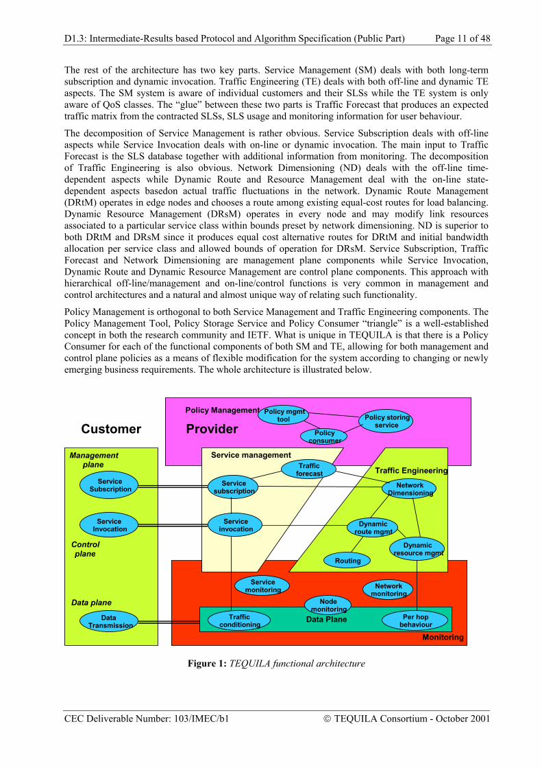
2.2 The TEQUILA Architecture TEQUILA has developed a high-level functional architecture according to the context, rationale and requirements detailed above. The architecture is illustrated in Figure 1 and includes management, control and data-plane functionality. The QoS architecture shows the basic interactions between the provider and the customer, i.e. service subscription, service invocation and data-transmission. The customer may be a company, another (peer) network provider, an application service provider or a residential user.
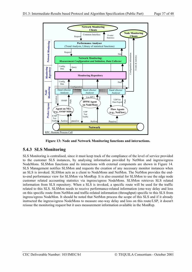
The data plane aspects are dictated by the DiffServ architecture and include Traffic Conditioning in the edge nodes, with incoming traffic policed and conditioned accordingly, and forwarding according to the Per-Hop Behaviour or service class in every network node. The next aspect close to the data plane is monitoring, which includes node monitoring, overall network monitoring and service or SLS monitoring. Monitoring functionality is used by the other parts of the architecture as detailed later in this document.
CEC Deliverable Number: 103/IMEC/b1 TEQUILA Consortium - October 2001
D1.3: Intermediate-Results based Protocol and Algorithm Specification (Public Part) Page 11 of 48
The rest of the architecture has two key parts. Service Management (SM) deals with both long-term subscription and dynamic invocation. Traffic Engineering (TE) deals with both off-line and dynamic TE aspects. The SM system is aware of individual customers and their SLSs while the TE system is only aware of QoS classes. The “glue” between these two parts is Traffic Forecast that produces an expected traffic matrix from the contracted SLSs, SLS usage and monitoring information for user behaviour.
The decomposition of Service Management is rather obvious. Service Subscription deals with off-line aspects while Service Invocation deals with on-line or dynamic invocation. The main input to Traffic Forecast is the SLS database together with additional information from monitoring. The decomposition of Traffic Engineering is also obvious. Network Dimensioning (ND) deals with the off-line time-dependent aspects while Dynamic Route and Resource Management deal with the on-line state-dependent aspects basedon actual traffic fluctuations in the network. Dynamic Route Management (DRtM) operates in edge nodes and chooses a route among existing equal-cost routes for load balancing. Dynamic Resource Management (DRsM) operates in every node and may modify link resources associated to a particular service class within bounds preset by network dimensioning. ND is superior to both DRtM and DRsM since it produces equal cost alternative routes for DRtM and initial bandwidth allocation per service class and allowed bounds of operation for DRsM. Service Subscription, Traffic Forecast and Network Dimensioning are management plane components while Service Invocation, Dynamic Route and Dynamic Resource Management are control plane components. This approach with hierarchical off-line/management and on-line/control functions is very common in management and control architectures and a natural and almost unique way of relating such functionality.
Policy Management is orthogonal to both Service Management and Traffic Engineering components. The Policy Management Tool, Policy Storage Service and Policy Consumer “triangle” is a well-established concept in both the research community and IETF. What is unique in TEQUILA is that there is a Policy Consumer for each of the functional components of both SM and TE, allowing for both management and control plane policies as a means of flexible modification for the system according to changing or newly emerging business requirements. The whole architecture is illustrated below.
Service management Traffic Engineering
Data Plane
Monitoring
Policy Management
Policy consumer
Policy mgmt tool
Servicesubscription
Serviceinvocation
Trafficforecast
Dynamicresource mgmt
Dynamic route mgmt
Routing
Per hop behaviour Traffic
conditioning
NetworkDimensioning
Policy storingservice
Node monitoring
Service Subscription
Service Invocation
Data Transmission
Customer
Management plane
Control plane
Data plane
Provider
Network monitoring
Servicemonitoring
Figure 1: TEQUILA functional architecture
CEC Deliverable Number: 103/IMEC/b1 TEQUILA Consortium - October 2001
D1.3: Intermediate-Results based Protocol and Algorithm Specification (Public Part) Page 12 of 48
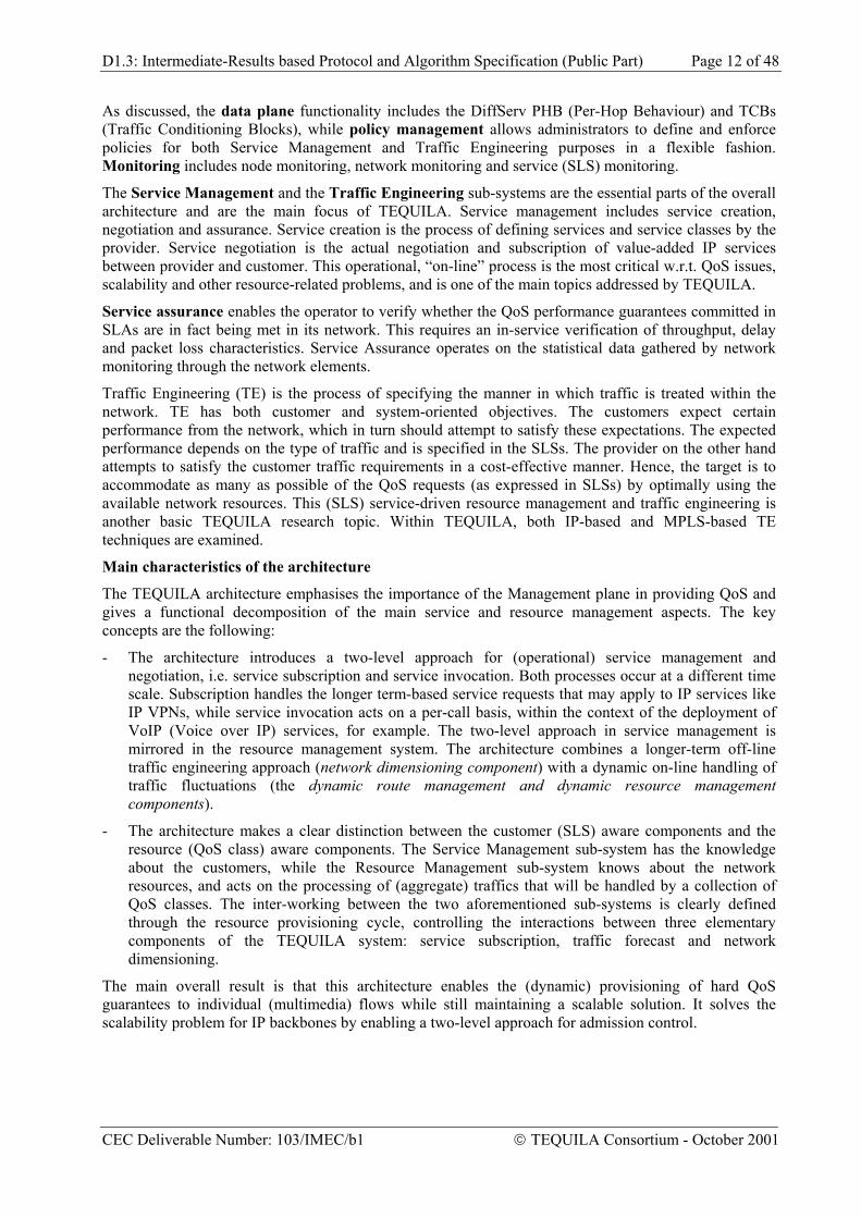
As discussed, the data plane functionality includes the DiffServ PHB (Per-Hop Behaviour) and TCBs (Traffic Conditioning Blocks), while policy management allows administrators to define and enforce policies for both Service Management and Traffic Engineering purposes in a flexible fashion. Monitoring includes node monitoring, network monitoring and service (SLS) monitoring.
The Service Management and the Traffic Engineering sub-systems are the essential parts of the overall architecture and are the main focus of TEQUILA. Service management includes service creation, negotiation and assurance. Service creation is the process of defining services and service classes by the provider. Service negotiation is the actual negotiation and subscription of value-added IP services between provider and customer. This operational, “on-line” process is the most critical w.r.t. QoS issues, scalability and other resource-related problems, and is one of the main topics addressed by TEQUILA.
Service assurance enables the operator to verify whether the QoS performance guarantees committed in SLAs are in fact being met in its network. This requires an in-service verification of throughput, delay and packet loss characteristics. Service Assurance operates on the statistical data gathered by network monitoring through the network elements.
Traffic Engineering (TE) is the process of specifying the manner in which traffic is treated within the network. TE has both customer and system-oriented objectives. The customers expect certain performance from the network, which in turn should attempt to satisfy these expectations. The expected performance depends on the type of traffic and is specified in the SLSs. The provider on the other hand attempts to satisfy the customer traffic requirements in a cost-effective manner. Hence, the target is to accommodate as many as possible of the QoS requests (as expressed in SLSs) by optimally using the available network resources. This (SLS) service-driven resource management and traffic engineering is another basic TEQUILA research topic. Within TEQUILA, both IP-based and MPLS-based TE techniques are examined.
Main characteristics of the architecture
The TEQUILA architecture emphasises the importance of the Management plane in providing QoS and gives a functional decomposition of the main service and resource management aspects. The key concepts are the following:
- The architecture introduces a two-level approach for (operational) service management and negotiation, i.e. service subscription and service invocation. Both processes occur at a different time scale. Subscription handles the longer term-based service requests that may apply to IP services like IP VPNs, while service invocation acts on a per-call basis, within the context of the deployment of VoIP (Voice over IP) services, for example. The two-level approach in service management is mirrored in the resource management system. The architecture combines a longer-term off-line traffic engineering approach (network dimensioning component) with a dynamic on-line handling of traffic fluctuations (the dynamic route management and dynamic resource management components).
- The architecture makes a clear distinction between the customer (SLS) aware components and the resource (QoS class) aware components. The Service Management sub-system has the knowledge about the customers, while the Resource Management sub-system knows about the network resources, and acts on the processing of (aggregate) traffics that will be handled by a collection of QoS classes. The inter-working between the two aforementioned sub-systems is clearly defined through the resource provisioning cycle, controlling the interactions between three elementary components of the TEQUILA system: service subscription, traffic forecast and network dimensioning.
The main overall result is that this architecture enables the (dynamic) provisioning of hard QoS guarantees to individual (multimedia) flows while still maintaining a scalable solution. It solves the scalability problem for IP backbones by enabling a two-level approach for admission control.
CEC Deliverable Number: 103/IMEC/b1 TEQUILA Consortium - October 2001
D1.3: Intermediate-Results based Protocol and Algorithm Specification (Public Part) Page 13 of 48
3 SERVICE MANAGEMENT
3.1 Introduction This section concentrates on the Service Management aspects of the TEQUILA architecture and is structured as follows. In subsection 3.2 we propose a layered service model for DiffServ and a clear concept of an IP transport service and QoS classes. Subsection 3.3 is the main section and outlines service aspectis of the TEQUILA functional model. The architecture introduces a two-phase approach for service negation, i.e. service subscription followed by service invocation. The architecture also specifies the interworking between service and resource management based on the concept of the resource provisioning cycle. Subsection 3.4 illustrates the ideas by two working scenarios, i.e. a corporate IP VPN and an NGN architecture where an IP backbone connects a number of Trunking Gateways.
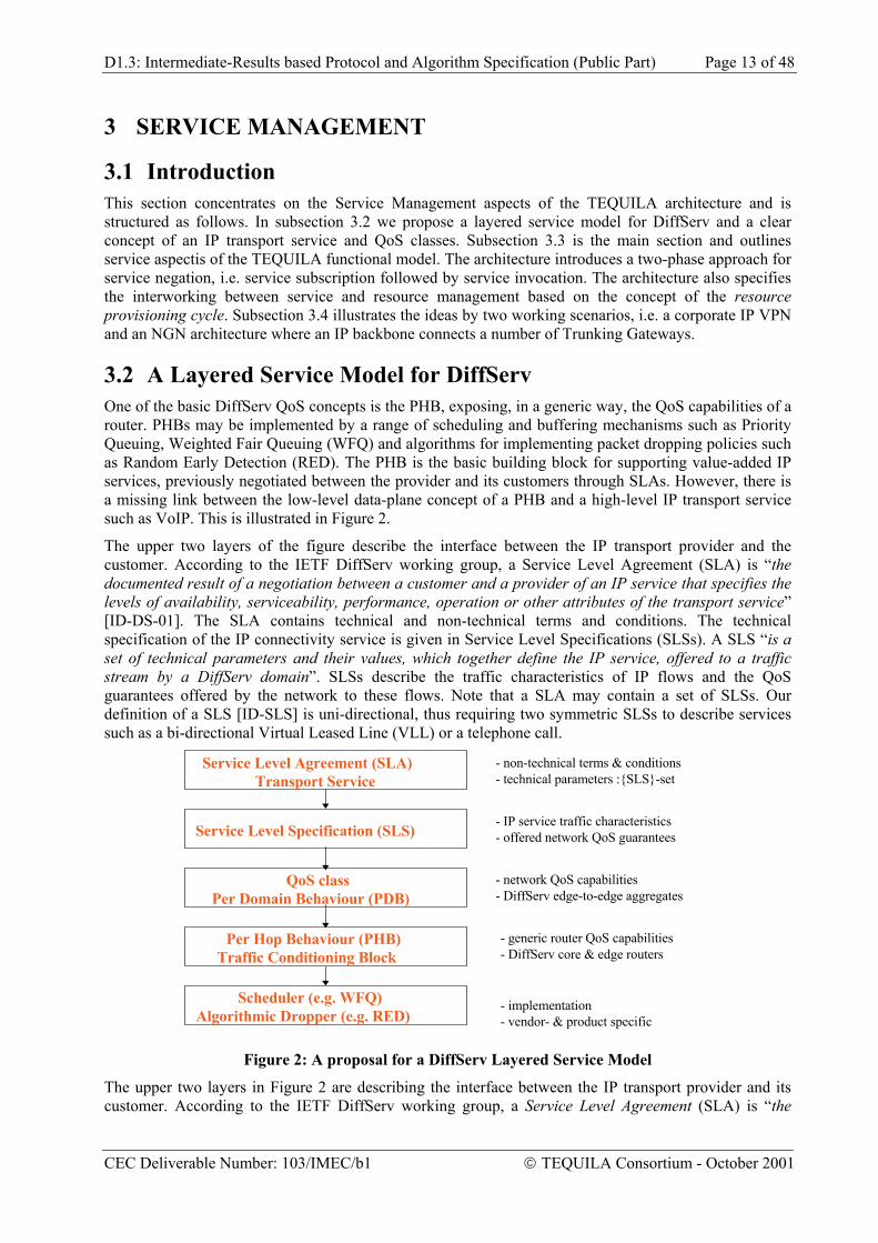
3.2 A Layered Service Model for DiffServ One of the basic DiffServ QoS concepts is the PHB, exposing, in a generic way, the QoS capabilities of a router. PHBs may be implemented by a range of scheduling and buffering mechanisms such as Priority Queuing, Weighted Fair Queuing (WFQ) and algorithms for implementing packet dropping policies such as Random Early Detection (RED). The PHB is the basic building block for supporting value-added IP services, previously negotiated between the provider and its customers through SLAs. However, there is a missing link between the low-level data-plane concept of a PHB and a high-level IP transport service such as VoIP. This is illustrated in Figure 2.
The upper two layers of the figure describe the interface between the IP transport provider and the customer. According to the IETF DiffServ working group, a Service Level Agreement (SLA) is “the documented result of a negotiation between a customer and a provider of an IP service that specifies the levels of availability, serviceability, performance, operation or other attributes of the transport service” [ID-DS-01]. The SLA contains technical and non-technical terms and conditions. The technical specification of the IP connectivity service is given in Service Level Specifications (SLSs). A SLS “is a set of technical parameters and their values, which together define the IP service, offered to a traffic stream by a DiffServ domain”. SLSs describe the traffic characteristics of IP flows and the QoS guarantees offered by the network to these flows. Note that a SLA may contain a set of SLSs. Our definition of a SLS [ID-SLS] is uni-directional, thus requiring two symmetric SLSs to describe services such as a bi-directional Virtual Leased Line (VLL) or a telephone call.
Figure 2: A proposal for a DiffServ Layered Service Model
The upper two layers in Figure 2 are describing the interface between the IP transport provider and its customer. According to the IETF DiffServ working group, a Service Level Agreement (SLA) is “the
CEC Deliverable Number: 103/IMEC/b1 TEQUILA Consortium - October 2001
D1.3: Intermediate-Results based Protocol and Algorithm Specification (Public Part) Page 14 of 48
documented result of a negotiation between a customer and a provider of an IP service that specifies the levels of availability, serviceability, performance, operation or other attributes of the transport service” [ID-DS]. The SLA contains technical and non-technical terms and conditions. The technical specification of the IP connectivity service is given in Service Level Specifications (SLSs). An SLS “is a set of technical parameters and their values, which together define the IP service, offered to a traffic stream by a DiffServ domain”. SLSs describe the traffic characteristics of IP flows and the QoS guarantees offered by the network to these flows. Remark that a SLA may contain a set of SLSs. As an SLS is by definition uni-directional, the description of e.g. a bi-directional Virtual Leased Line (VLL) or phone call requires two SLSs.
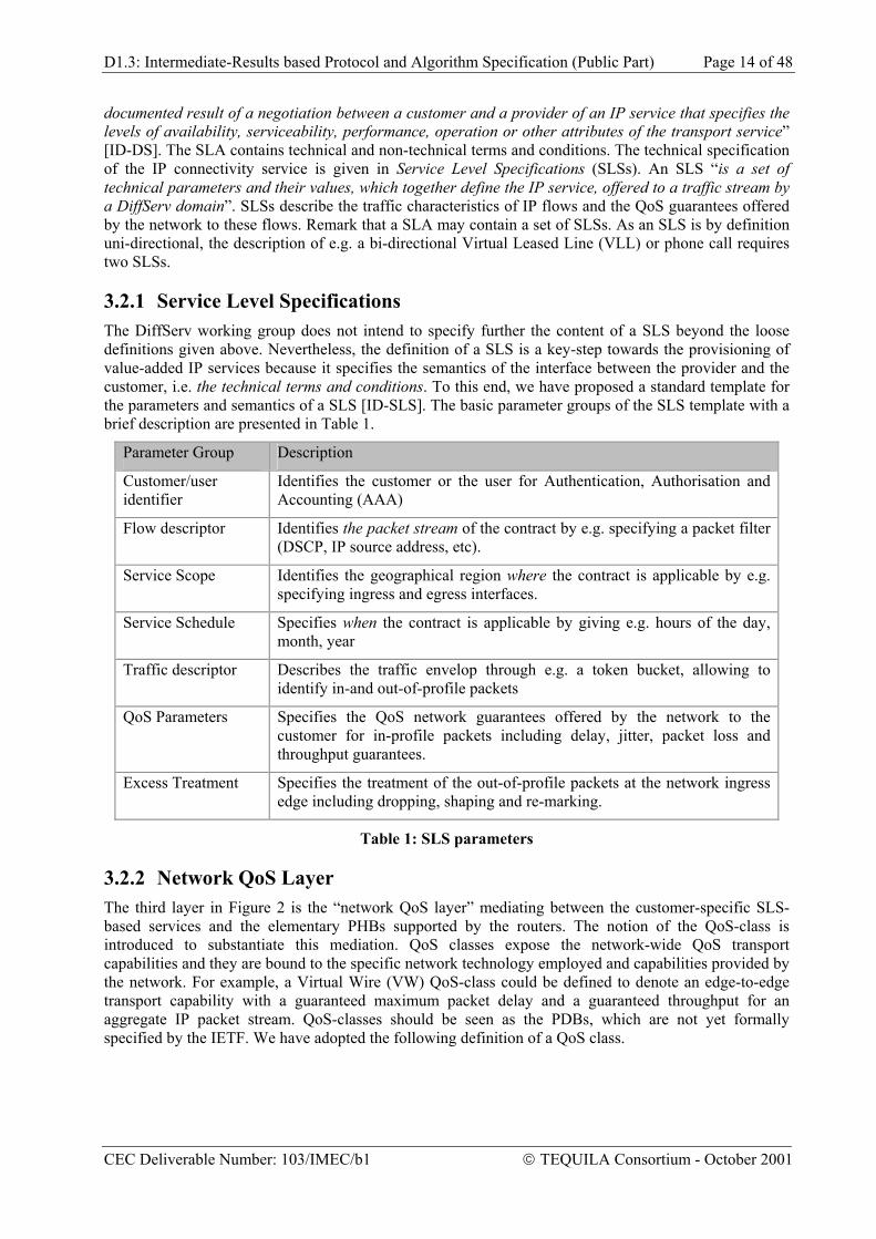
3.2.1 Service Level Specifications The DiffServ working group does not intend to specify further the content of a SLS beyond the loose definitions given above. Nevertheless, the definition of a SLS is a key-step towards the provisioning of value-added IP services because it specifies the semantics of the interface between the provider and the customer, i.e. the technical terms and conditions. To this end, we have proposed a standard template for the parameters and semantics of a SLS [ID-SLS]. The basic parameter groups of the SLS template with a brief description are presented in Table 1.
Parameter Group Description
Customer/user identifier
Identifies the customer or the user for Authentication, Authorisation and Accounting (AAA)
Flow descriptor Identifies the packet stream of the contract by e.g. specifying a packet filter (DSCP, IP source address, etc).
Service Scope Identifies the geographical region where the contract is applicable by e.g. specifying ingress and egress interfaces.
Service Schedule Specifies when the contract is applicable by giving e.g. hours of the day, month, year
Traffic descriptor Describes the traffic envelop through e.g. a token bucket, allowing to identify in-and out-of-profile packets
QoS Parameters Specifies the QoS network guarantees offered by the network to the customer for in-profile packets including delay, jitter, packet loss and throughput guarantees.
Excess Treatment Specifies the treatment of the out-of-profile packets at the network ingress edge including dropping, shaping and re-marking.
Table 1: SLS parameters
3.2.2 Network QoS Layer The third layer in Figure 2 is the “network QoS layer” mediating between the customer-specific SLS-based services and the elementary PHBs supported by the routers. The notion of the QoS-class is introduced to substantiate this mediation. QoS classes expose the network-wide QoS transport capabilities and they are bound to the specific network technology employed and capabilities provided by the network. For example, a Virtual Wire (VW) QoS-class could be defined to denote an edge-to-edge transport capability with a guaranteed maximum packet delay and a guaranteed throughput for an aggregate IP packet stream. QoS-classes should be seen as the PDBs, which are not yet formally specified by the IETF. We have adopted the following definition of a QoS class.
CEC Deliverable Number: 103/IMEC/b1 TEQUILA Consortium - October 2001
D1.3: Intermediate-Results based Protocol and Algorithm Specification (Public Part) Page 15 of 48
Parameter Comments Ordered Aggregate
The allowed values are: Expedited Forwarding (EF), Assured Forwarding 1-4 (AF1, AF2, AF3, AF4), Best Effort (BE)
Delay The delay is the maximum edge-to-edge delay that the in-profile packets of a certain IP stream should experience. It is a continuous parameter that may be worst case (deterministic) or percentile (probabilistic).
Packet Loss
The packet loss is the upper bound of the edge-to-edge packet loss probability that in-profile profile packets of an IP stream should have.
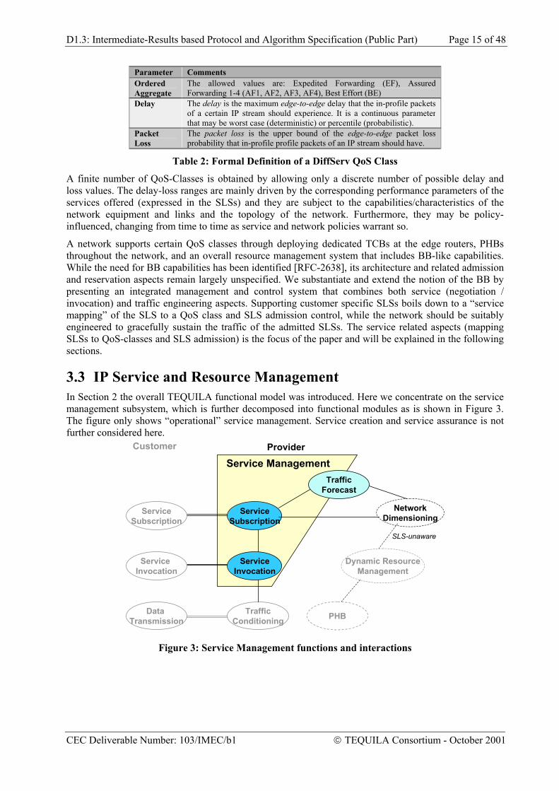
Table 2: Formal Definition of a DiffServ QoS Class
A finite number of QoS-Classes is obtained by allowing only a discrete number of possible delay and loss values. The delay-loss ranges are mainly driven by the corresponding performance parameters of the services offered (expressed in the SLSs) and they are subject to the capabilities/characteristics of the network equipment and links and the topology of the network. Furthermore, they may be policy-influenced, changing from time to time as service and network policies warrant so.
A network supports certain QoS classes through deploying dedicated TCBs at the edge routers, PHBs throughout the network, and an overall resource management system that includes BB-like capabilities. While the need for BB capabilities has been identified [RFC-2638], its architecture and related admission and reservation aspects remain largely unspecified. We substantiate and extend the notion of the BB by presenting an integrated management and control system that combines both service (negotiation / invocation) and traffic engineering aspects. Supporting customer specific SLSs boils down to a “service mapping” of the SLS to a QoS class and SLS admission control, while the network should be suitably engineered to gracefully sustain the traffic of the admitted SLSs. The service related aspects (mapping SLSs to QoS-classes and SLS admission) is the focus of the paper and will be explained in the following sections.
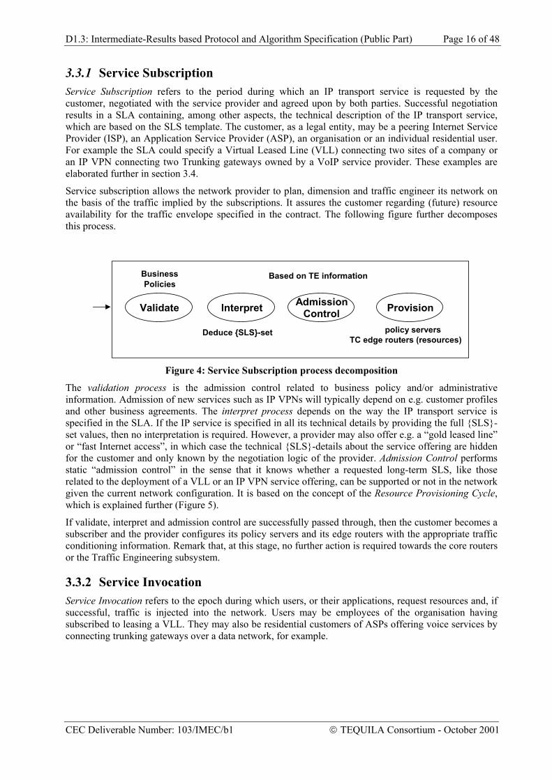
3.3 IP Service and Resource Management In Section 2 the overall TEQUILA functional model was introduced. Here we concentrate on the service management subsystem, which is further decomposed into functional modules as is shown in Figure 3. The figure only shows “operational” service management. Service creation and service assurance is not further considered here.
NetworkDimensioning
ServiceSubscription
ServiceInvocation
TrafficForecast
TrafficConditioning
ServiceSubscription
Service Invocation
Data Transmission
Customer Provider
Dynamic ResourceManagement
SLS-unaware
PHB
Service Management
Figure 3: Service Management functions and interactions
CEC Deliverable Number: 103/IMEC/b1 TEQUILA Consortium - October 2001
D1.3: Intermediate-Results based Protocol and Algorithm Specification (Public Part) Page 16 of 48
3.3.1 Service Subscription Service Subscription refers to the period during which an IP transport service is requested by the customer, negotiated with the service provider and agreed upon by both parties. Successful negotiation results in a SLA containing, among other aspects, the technical description of the IP transport service, which are based on the SLS template. The customer, as a legal entity, may be a peering Internet Service Provider (ISP), an Application Service Provider (ASP), an organisation or an individual residential user. For example the SLA could specify a Virtual Leased Line (VLL) connecting two sites of a company or an IP VPN connecting two Trunking gateways owned by a VoIP service provider. These examples are elaborated further in section 3.4.
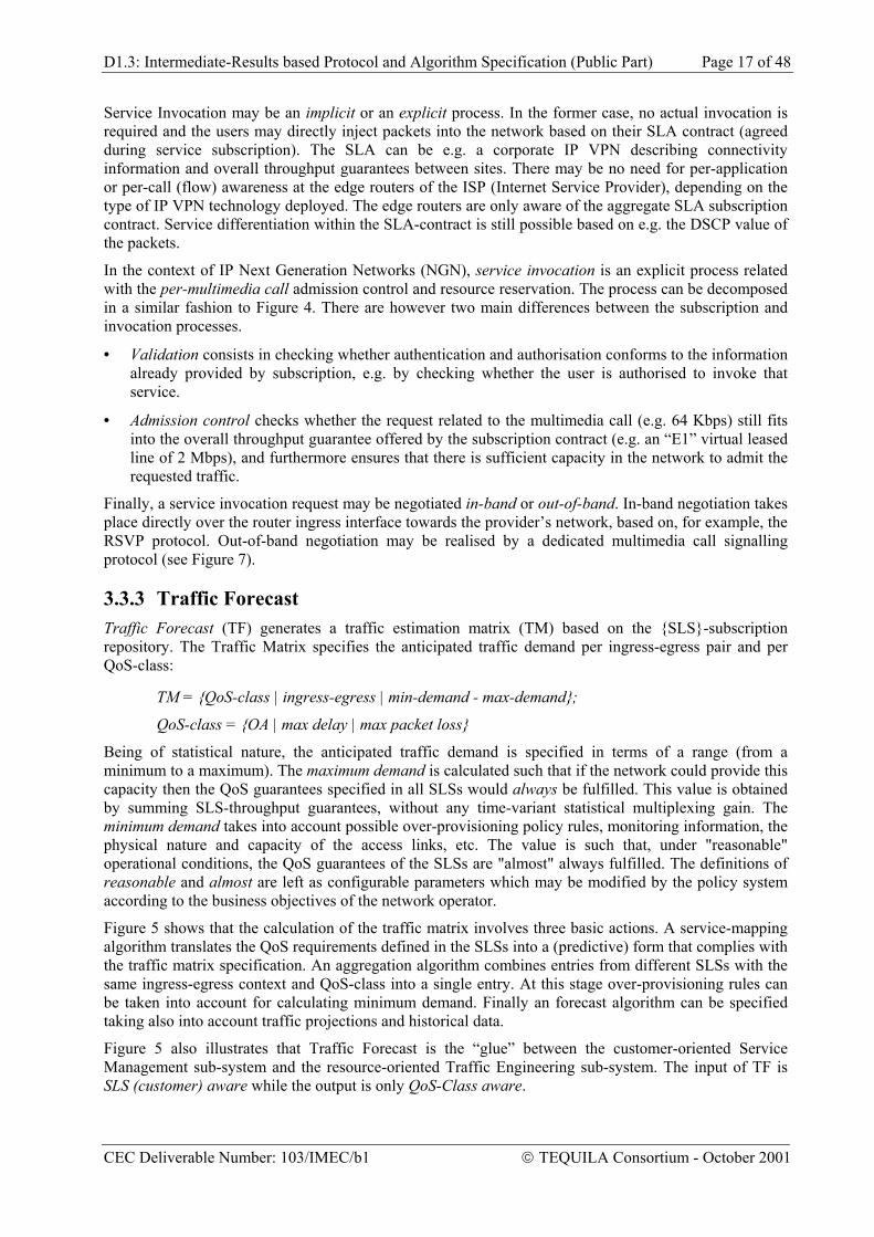
Service subscription allows the network provider to plan, dimension and traffic engineer its network on the basis of the traffic implied by the subscriptions. It assures the customer regarding (future) resource availability for the traffic envelope specified in the contract. The following figure further decomposes this process.
Deduce {SLS}-set
Validate Interpret AdmissionControl Provision
policy serversTC edge routers (resources)
Based on TE informationBusinessPolicies
Figure 4: Service Subscription process decomposition
The validation process is the admission control related to business policy and/or administrative information. Admission of new services such as IP VPNs will typically depend on e.g. customer profiles and other business agreements. The interpret process depends on the way the IP transport service is specified in the SLA. If the IP service is specified in all its technical details by providing the full {SLS}-set values, then no interpretation is required. However, a provider may also offer e.g. a “gold leased line” or “fast Internet access”, in which case the technical {SLS}-details about the service offering are hidden for the customer and only known by the negotiation logic of the provider. Admission Control performs static “admission control” in the sense that it knows whether a requested long-term SLS, like those related to the deployment of a VLL or an IP VPN service offering, can be supported or not in the network given the current network configuration. It is based on the concept of the Resource Provisioning Cycle, which is explained further (Figure 5).
If validate, interpret and admission control are successfully passed through, then the customer becomes a subscriber and the provider configures its policy servers and its edge routers with the appropriate traffic conditioning information. Remark that, at this stage, no further action is required towards the core routers or the Traffic Engineering subsystem.
3.3.2 Service Invocation Service Invocation refers to the epoch during which users, or their applications, request resources and, if successful, traffic is injected into the network. Users may be employees of the organisation having subscribed to leasing a VLL. They may also be residential customers of ASPs offering voice services by connecting trunking gateways over a data network, for example.
CEC Deliverable Number: 103/IMEC/b1 TEQUILA Consortium - October 2001
D1.3: Intermediate-Results based Protocol and Algorithm Specification (Public Part) Page 17 of 48
Service Invocation may be an implicit or an explicit process. In the former case, no actual invocation is required and the users may directly inject packets into the network based on their SLA contract (agreed during service subscription). The SLA can be e.g. a corporate IP VPN describing connectivity information and overall throughput guarantees between sites. There may be no need for per-application or per-call (flow) awareness at the edge routers of the ISP (Internet Service Provider), depending on the type of IP VPN technology deployed. The edge routers are only aware of the aggregate SLA subscription contract. Service differentiation within the SLA-contract is still possible based on e.g. the DSCP value of the packets.
In the context of IP Next Generation Networks (NGN), service invocation is an explicit process related with the per-multimedia call admission control and resource reservation. The process can be decomposed in a similar fashion to Figure 4. There are however two main differences between the subscription and invocation processes.
• Validation consists in checking whether authentication and authorisation conforms to the information already provided by subscription, e.g. by checking whether the user is authorised to invoke that service.
• Admission control checks whether the request related to the multimedia call (e.g. 64 Kbps) still fits into the overall throughput guarantee offered by the subscription contract (e.g. an “E1” virtual leased line of 2 Mbps), and furthermore ensures that there is sufficient capacity in the network to admit the requested traffic.
Finally, a service invocation request may be negotiated in-band or out-of-band. In-band negotiation takes place directly over the router ingress interface towards the provider’s network, based on, for example, the RSVP protocol. Out-of-band negotiation may be realised by a dedicated multimedia call signalling protocol (see Figure 7).
3.3.3 Traffic Forecast Traffic Forecast (TF) generates a traffic estimation matrix (TM) based on the {SLS}-subscription repository. The Traffic Matrix specifies the anticipated traffic demand per ingress-egress pair and per QoS-class:
Being of statistical nature, the anticipated traffic demand is specified in terms of a range (from a minimum to a maximum). The maximum demand is calculated such that if the network could provide this capacity then the QoS guarantees specified in all SLSs would always be fulfilled. This value is obtained by summing SLS-throughput guarantees, without any time-variant statistical multiplexing gain. The minimum demand takes into account possible over-provisioning policy rules, monitoring information, the physical nature and capacity of the access links, etc. The value is such that, under "reasonable" operational conditions, the QoS guarantees of the SLSs are "almost" always fulfilled. The definitions of reasonable and almost are left as configurable parameters which may be modified by the policy system according to the business objectives of the network operator.
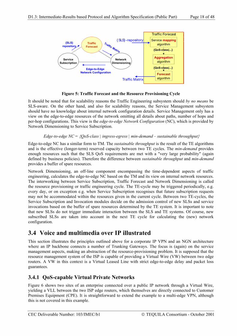
Figure 5 shows that the calculation of the traffic matrix involves three basic actions. A service-mapping algorithm translates the QoS requirements defined in the SLSs into a (predictive) form that complies with the traffic matrix specification. An aggregation algorithm combines entries from different SLSs with the same ingress-egress context and QoS-class into a single entry. At this stage over-provisioning rules can be taken into account for calculating minimum demand. Finally an forecast algorithm can be specified taking also into account traffic projections and historical data.
Figure 5 also illustrates that Traffic Forecast is the “glue” between the customer-oriented Service Management sub-system and the resource-oriented Traffic Engineering sub-system. The input of TF is SLS (customer) aware while the output is only QoS-Class aware.
CEC Deliverable Number: 103/IMEC/b1 TEQUILA Consortium - October 2001
D1.3: Intermediate-Results based Protocol and Algorithm Specification (Public Part) Page 18 of 48
Network Dimensioning
TrafficForecast
ServiceSubscription
Edge-to-Edge Network Configuration
Traffic Matrix
{SLS}repository
algorithm
Servicealgorithm
{QoS-class|...}
algorithm
{ SLS} -repository
Traffic Matrix
{QoS-class|...}
Traffic Forecast
Forecast
mapping
Aggregation
Figure 5: Traffic Forecast and the Resource Provisioning Cycle
It should be noted that for scalability reasons the Traffic Engineering subsystem should by no means be SLS-aware. On the other hand, and also for scalability reasons, the Service Management subsystem should have no knowledge about internal network configuration details. Service Management only has a view on the edge-to-edge resources of the network omitting all details about paths, number of hops and per-hop configurations. This view is the edge-to-edge Network Configuration (NC), which is provided by Network Dimensioning to Service Subscription.
Edge-to-edge NC has a similar form to TM. The sustainable throughput is the result of the TE algorithms and is the effective (longer-term) reserved capacity between two TE cycles. The min-demand provides enough resources such that the SLS QoS requirements are met with a "very large probability" (again defined by business policies). Therefore the difference between sustainable throughput and min-demand provides a buffer of spare resources.
Network Dimensioning, an off-line component encompassing the time-dependent aspects of traffic engineering, calculates the edge-to-edge NC based on the TM and its view on internal network resources. The interworking between Service Subscription, Traffic Forecast and Network Dimensioning is called the resource provisioning or traffic engineering cycle. The TE-cycle may be triggered periodically, e.g. every day, or on exception e.g. when Service Subscription recognises that future subscription requests may not be accommodated within the resources given in the current cycle. Between two TE-cycles, the Service Subscription and Invocation modules decide on the admission control of new SLSs and service invocations based on the buffer of spare resources determined by the TE system. It is important to note that new SLSs do not trigger immediate interaction between the SLS and TE systems. Of course, new subscribed SLSs are taken into account in the next TE cycle for calculating the (new) network configuration.
3.4 Voice and multimedia over IP illustrated This section illustrates the principles outlined above for a corporate IP VPN and an NGN architecture where an IP backbone connects a number of Trunking Gateways. The focus is (again) on the service management aspects, making an abstraction of the resource-provisioning problem. It is supposed that the resource management system of the ISP is capable of providing a Virtual Wire (VW) between two edge routers. A VW in this context is a Virtual Leased Line with strict edge-to-edge delay and packet loss guarantees.
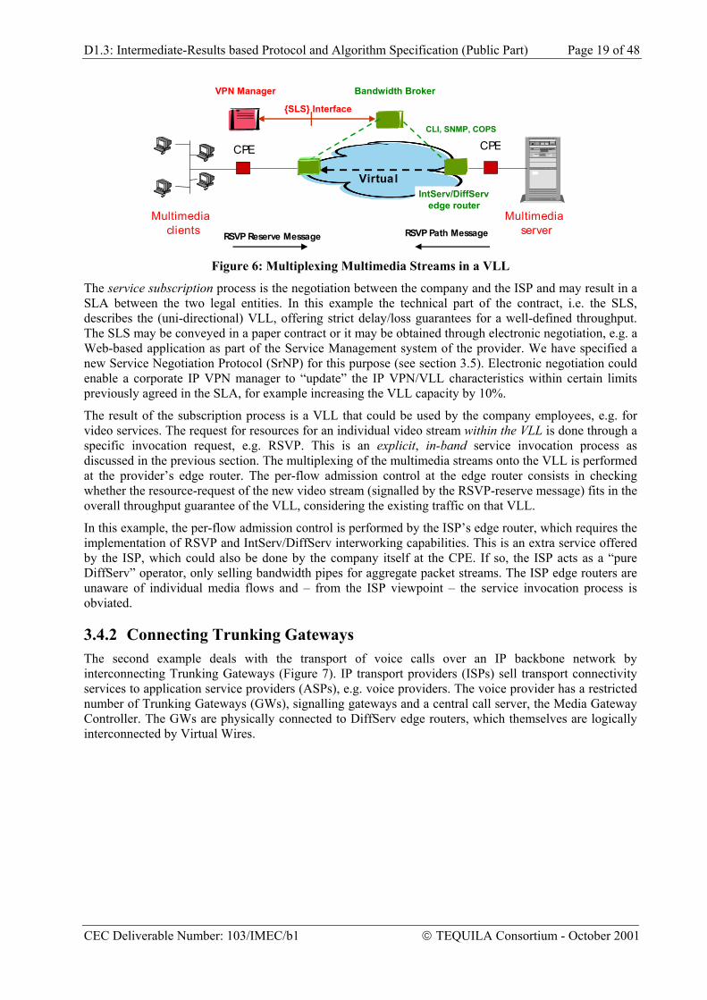
3.4.1 QoS-capable Virtual Private Networks Figure 6 shows two sites of an enterprise connected over a public IP network through a Virtual Wire, yielding a VLL between the two ISP edge routers, which themselves are directly connected to Customer Premises Equipment (CPE). It is straightforward to extend the example to a multi-edge VPN, although this is not covered in this example.
CEC Deliverable Number: 103/IMEC/b1 TEQUILA Consortium - October 2001
D1.3: Intermediate-Results based Protocol and Algorithm Specification (Public Part) Page 19 of 48
IP
Bandwidth Broker
Virtual
CPE CPE
IntServ/DiffServedge router
RSVP Reserve Message RSVP Path Message
CLI, SNMP, COPS
VPN Manager
{SLS} Interface
Multimediaclients
Multimediaserver
Figure 6: Multiplexing Multimedia Streams in a VLL
The service subscription process is the negotiation between the company and the ISP and may result in a SLA between the two legal entities. In this example the technical part of the contract, i.e. the SLS, describes the (uni-directional) VLL, offering strict delay/loss guarantees for a well-defined throughput. The SLS may be conveyed in a paper contract or it may be obtained through electronic negotiation, e.g. a Web-based application as part of the Service Management system of the provider. We have specified a new Service Negotiation Protocol (SrNP) for this purpose (see section 3.5). Electronic negotiation could enable a corporate IP VPN manager to “update” the IP VPN/VLL characteristics within certain limits previously agreed in the SLA, for example increasing the VLL capacity by 10%.
The result of the subscription process is a VLL that could be used by the company employees, e.g. for video services. The request for resources for an individual video stream within the VLL is done through a specific invocation request, e.g. RSVP. This is an explicit, in-band service invocation process as discussed in the previous section. The multiplexing of the multimedia streams onto the VLL is performed at the provider’s edge router. The per-flow admission control at the edge router consists in checking whether the resource-request of the new video stream (signalled by the RSVP-reserve message) fits in the overall throughput guarantee of the VLL, considering the existing traffic on that VLL.
In this example, the per-flow admission control is performed by the ISP’s edge router, which requires the implementation of RSVP and IntServ/DiffServ interworking capabilities. This is an extra service offered by the ISP, which could also be done by the company itself at the CPE. If so, the ISP acts as a “pure DiffServ” operator, only selling bandwidth pipes for aggregate packet streams. The ISP edge routers are unaware of individual media flows and – from the ISP viewpoint – the service invocation process is obviated.
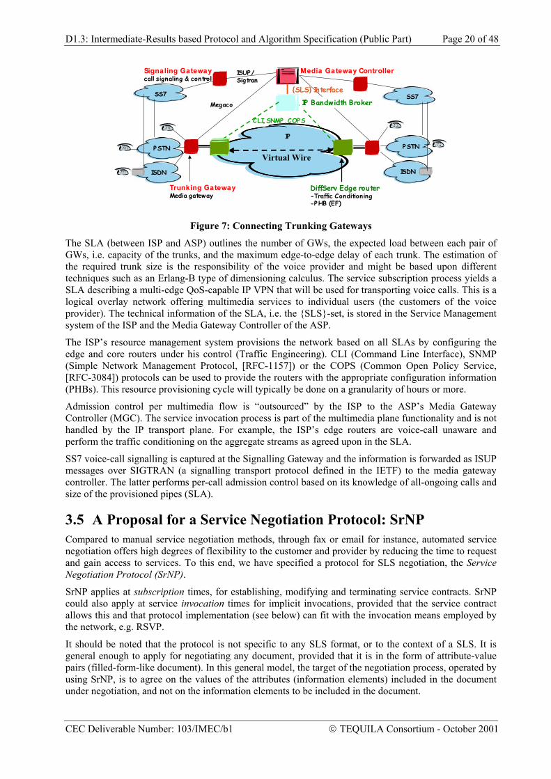
3.4.2 Connecting Trunking Gateways The second example deals with the transport of voice calls over an IP backbone network by interconnecting Trunking Gateways (Figure 7). IP transport providers (ISPs) sell transport connectivity services to application service providers (ASPs), e.g. voice providers. The voice provider has a restricted number of Trunking Gateways (GWs), signalling gateways and a central call server, the Media Gateway Controller. The GWs are physically connected to DiffServ edge routers, which themselves are logically interconnected by Virtual Wires.
CEC Deliverable Number: 103/IMEC/b1 TEQUILA Consortium - October 2001
D1.3: Intermediate-Results based Protocol and Algorithm Specification (Public Part) Page 20 of 48
The SLA (between ISP and ASP) outlines the number of GWs, the expected load between each pair of GWs, i.e. capacity of the trunks, and the maximum edge-to-edge delay of each trunk. The estimation of the required trunk size is the responsibility of the voice provider and might be based upon different techniques such as an Erlang-B type of dimensioning calculus. The service subscription process yields a SLA describing a multi-edge QoS-capable IP VPN that will be used for transporting voice calls. This is a logical overlay network offering multimedia services to individual users (the customers of the voice provider). The technical information of the SLA, i.e. the {SLS}-set, is stored in the Service Management system of the ISP and the Media Gateway Controller of the ASP.
The ISP’s resource management system provisions the network based on all SLAs by configuring the edge and core routers under his control (Traffic Engineering). CLI (Command Line Interface), SNMP (Simple Network Management Protocol, [RFC-1157]) or the COPS (Common Open Policy Service, [RFC-3084]) protocols can be used to provide the routers with the appropriate configuration information (PHBs). This resource provisioning cycle will typically be done on a granularity of hours or more.
Admission control per multimedia flow is “outsourced” by the ISP to the ASP’s Media Gateway Controller (MGC). The service invocation process is part of the multimedia plane functionality and is not handled by the IP transport plane. For example, the ISP’s edge routers are voice-call unaware and perform the traffic conditioning on the aggregate streams as agreed upon in the SLA.
SS7 voice-call signalling is captured at the Signalling Gateway and the information is forwarded as ISUP messages over SIGTRAN (a signalling transport protocol defined in the IETF) to the media gateway controller. The latter performs per-call admission control based on its knowledge of all-ongoing calls and size of the provisioned pipes (SLA).
3.5 A Proposal for a Service Negotiation Protocol: SrNP Compared to manual service negotiation methods, through fax or email for instance, automated service negotiation offers high degrees of flexibility to the customer and provider by reducing the time to request and gain access to services. To this end, we have specified a protocol for SLS negotiation, the Service Negotiation Protocol (SrNP).
SrNP applies at subscription times, for establishing, modifying and terminating service contracts. SrNP could also apply at service invocation times for implicit invocations, provided that the service contract allows this and that protocol implementation (see below) can fit with the invocation means employed by the network, e.g. RSVP.
It should be noted that the protocol is not specific to any SLS format, or to the context of a SLS. It is general enough to apply for negotiating any document, provided that it is in the form of attribute-value pairs (filled-form-like document). In this general model, the target of the negotiation process, operated by using SrNP, is to agree on the values of the attributes (information elements) included in the document under negotiation, and not on the information elements to be included in the document.
CEC Deliverable Number: 103/IMEC/b1 TEQUILA Consortium - October 2001
D1.3: Intermediate-Results based Protocol and Algorithm Specification (Public Part) Page 21 of 48
In the above context, SrNP provides for appropriate messages and procedures required for pursuing an agreement, thus offering the necessary primitives required to operate the particular negotiation logic (responsible for determining the terms and conditions for establishing an agreement).
SrNP is session-oriented and adopts a client-server, dialogue-based (half-duplex) approach. Specifically, SrNP operates as follows. The client issues proposals and the server responds by issuing revisions (indicating alternatives on client’s proposal) or an agreed proposal (agreement on the last sent proposal by the client). The protocol concludes the negotiation process when the server responds with an agreed proposal and the client accepts it, or when either party rejects the other party’s response. To ensure graceful termination, the protocol utilises a response timer for guaranteeing that a party cannot wait forever to receive a response from the other party.
SrNP also offers the features of ‘take it or leave it’ and ‘please wait’. One party (the client or the server) may designate one of its responses as being its last word (last proposal, last revision), meaning that the other party must respond with a definite answer (accept or reject). The protocol allows for the server to hold the proposal i.e. to postpone its response to the client’s proposal (e.g. should the server negotiation logic sees that an agreement is likely to be reached in the near future). In this case an explicit confirmation by the client is required (accept to hold, specifying also the details of the contact point to resume the negotiation process).
Figure 8 depicts alternative protocol stacks for realising SrNP. SrNP messages could be encoded in ASCII, BER/TLVs or XML as convenient for the stack used. Note also that it could be possible to encapsulate SrNP messages in widely deployed protocols such as RSVP (by defining new TLVs) and COPS (by specifying a new client-type). The latter is required when SrNP is to be used at invocation times.
It should be noted that the semantics and format of the document under negotiation are transparent to the protocol itself, although in this instance we assume the SLS template specified in [ID-SLS].
Currently there are two implementations of SrNP; one based directly on TCP/IP and the other on HTTP. In both implementations, the SrNP messages as well as the SLA and the revised alternatives were encoded in XML.
TCP/IP
HTTP,SMTP,IIOP
ebXML MS
SrNP
Encapsulation in RSVP, COPS
Figure 8: SrNP Protocol Stacks
3.6 Summary In this section we addressed the Service Management aspects of the TEQUILA architecture. We started from a layered service model from DiffServ and continued with a detailed description of the proposed SLSs. We then discussed service subscription, service invocation, traffic forecast and the concept of the Resource Provisioning Cycle. We then presented two examples: QoS-capable Virtual Private Networks and Connected Trunking Gateways. We finally presented the proposed Service Negotiation Protocol (SrNP). A key aspect of the Service Management architecture is that it is aware of individual customer SLSs. This is unavoidable but despite this, the architecture exhibits high scalability since only the management plane Service Subscription component needs to be aware of the complete set of SLSs. The control plane Service Invocation component operating at edge routers needs to be configured to know all the SLSs to be invoked at the particular edge node. This increases relatively the complexity of edge routers but the core network remains unaware of individual SLSs and only aware of QoS-classes as detailed in the next section.
CEC Deliverable Number: 103/IMEC/b1 TEQUILA Consortium - October 2001
D1.3: Intermediate-Results based Protocol and Algorithm Specification (Public Part) Page 22 of 48
4 TRAFFIC ENGINEERING
4.1 Introduction In TEQUILA we have produced a framework for Service Level Specifications (SLSs) as described in section 3, we have designed an integrated management and control architecture [TEQ-01] and we are currently investigating both MPLS- and IP-based techniques for traffic engineering. In this section we present, techniques for network dimensioning, dynamic route and dynamic resource management, contrasting MPLS and IP-based approaches.
The rest of this section has the following structure. In subsection 4.2 we present a functional architecture for supporting quality of service in IP differentiated services; presenting briefly all its aspects but concentrating on the architectural decomposition of the traffic engineering part. In section 4.3 we present techniques for network dimensioning, in section 4.4 techniques for dynamic route management and in section 4.5 techniques for dynamic resource management. We finally conclude with a brief summary in section 4.6.
4.2 A functional model for QoS In the service management section we have described the TEQUILA functional model from a service management point of view. In the next section we will look at the funcional model again this time from a Traffic Engineering point of view.
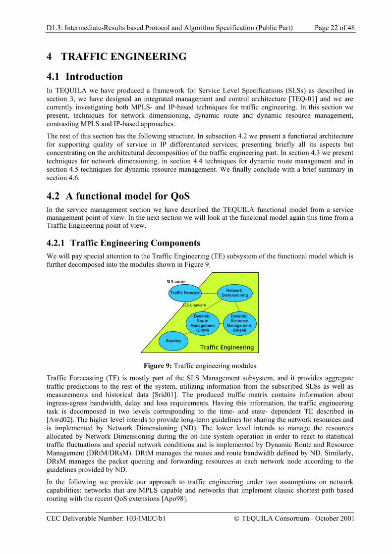
4.2.1 Traffic Engineering Components We will pay special attention to the Traffic Engineering (TE) subsystem of the functional model which is further decomposed into the modules shown in Figure 9.
Network Dimensioning
Dynamic Route
Management(DRtM)
Dynamic Resource
Management (DRsM)
Traffic Forecast
SLS aware
SLS unaware
Traffic EngineeringRouting
Network Dimensioning
Dynamic Route
Management(DRtM)
Dynamic Resource
Management (DRsM)
Traffic Forecast
SLS aware
SLS unaware
Traffic EngineeringRouting
Figure 9: Traffic engineering modules
Traffic Forecasting (TF) is mostly part of the SLS Management subsystem, and it provides aggregate traffic predictions to the rest of the system, utilizing information from the subscribed SLSs as well as measurements and historical data [Srid01]. The produced traffic matrix contains information about ingress-egress bandwidth, delay and loss requirements. Having this information, the traffic engineering task is decomposed in two levels corresponding to the time- and state- dependent TE described in [Awd02]. The higher level intends to provide long-term guidelines for sharing the network resources and is implemented by Network Dimensioning (ND). The lower level intends to manage the resources allocated by Network Dimensioning during the on-line system operation in order to react to statistical traffic fluctuations and special network conditions and is implemented by Dynamic Route and Resource Management (DRtM/DRsM). DRtM manages the routes and route bandwidth defined by ND. Similarly, DRsM manages the packet queuing and forwarding resources at each network node according to the guidelines provided by ND.
In the following we provide our approach to traffic engineering under two assumptions on network capabilities: networks that are MPLS capable and networks that implement classic shortest-path based routing with the recent QoS extensions [Apo98].
CEC Deliverable Number: 103/IMEC/b1 TEQUILA Consortium - October 2001
D1.3: Intermediate-Results based Protocol and Algorithm Specification (Public Part) Page 23 of 48
4.3 Network Dimensioning
4.3.1 MPLS-based Approach The MPLS approach to Network Dimensioning utilizes the set-up of explicitly routed paths without bandwidth reservation. This is done in order to provide guidelines to DRtM and DRsM on how to best accommodate the predicted traffic.
The entries of the traffic matrix are the traffic trunks [Li98]. Each trunk is the aggregation of a set of traffic flows characterized by the same ingress and egress nodes and performance requirements. Aggregating flows into trunks results in fewer entries thus increased scalability [Awd99]. In the multi-class setting we use in this work, the traffic class (called QoS-class in the remainder of this document) of the trunk is defined by the Ordered Aggregate (OA) [Blak98] bandwidth, maximum delay and loss probability requirements.
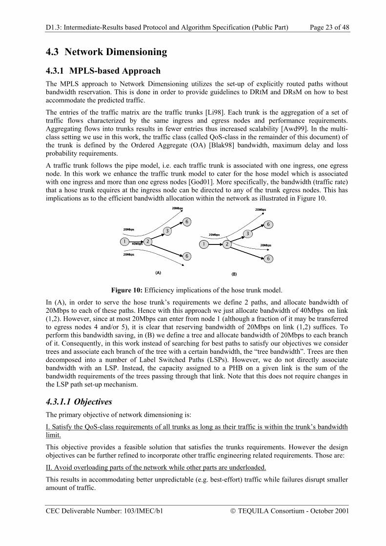
A traffic trunk follows the pipe model, i.e. each traffic trunk is associated with one ingress, one egress node. In this work we enhance the traffic trunk model to cater for the hose model which is associated with one ingress and more than one egress nodes [God01]. More specifically, the bandwidth (traffic rate) that a hose trunk requires at the ingress node can be directed to any of the trunk egress nodes. This has implications as to the efficient bandwidth allocation within the network as illustrated in Figure 10.
1
3
2
6
6
20Mbps
20Mbps
20Mbps
1
3
2
6
6
20Mbps
20Mbps
20Mbps
40Mbps
(A) (B)
1
3
2
6
6
20Mbps
20Mbps
20Mbps
1
3
2
6
6
20Mbps
20Mbps
20Mbps
1
3
2
6
6
20Mbps
20Mbps
20Mbps
40Mbps1
3
2
6
6
20Mbps
20Mbps
20Mbps
40Mbps
(A) (B)
Figure 10: Efficiency implications of the hose trunk model.
In (A), in order to serve the hose trunk’s requirements we define 2 paths, and allocate bandwidth of 20Mbps to each of these paths. Hence with this approach we just allocate bandwidth of 40Mbps on link (1,2). However, since at most 20Mbps can enter from node 1 (although a fraction of it may be transferred to egress nodes 4 and/or 5), it is clear that reserving bandwidth of 20Mbps on link (1,2) suffices. To perform this bandwidth saving, in (B) we define a tree and allocate bandwidth of 20Mbps to each branch of it. Consequently, in this work instead of searching for best paths to satisfy our objectives we consider trees and associate each branch of the tree with a certain bandwidth, the “tree bandwidth”. Trees are then decomposed into a number of Label Switched Paths (LSPs). However, we do not directly associate bandwidth with an LSP. Instead, the capacity assigned to a PHB on a given link is the sum of the bandwidth requirements of the trees passing through that link. Note that this does not require changes in the LSP path set-up mechanism.
4.3.1.1 Objectives The primary objective of network dimensioning is:
I. Satisfy the QoS-class requirements of all trunks as long as their traffic is within the trunk’s bandwidth limit.
This objective provides a feasible solution that satisfies the trunks requirements. However the design objectives can be further refined to incorporate other traffic engineering related requirements. Those are:
II. Avoid overloading parts of the network while other parts are underloaded.
This results in accommodating better unpredictable (e.g. best-effort) traffic while failures disrupt smaller amount of traffic.
CEC Deliverable Number: 103/IMEC/b1 TEQUILA Consortium - October 2001
D1.3: Intermediate-Results based Protocol and Algorithm Specification (Public Part) Page 24 of 48
Minimize the overall network cost.
With each link l and a given OA, we associate a cost function f(x), where x is the bandwidth allocated to the OA. This cost function may represent the link utilization but it may also be a function determined by administrative policies. We assume that f(x) is convex. Objective II above can be associated with the following optimization criteria:
)max(min lElF
∈ (1)
∑∈ El
lFmin (2)
The first criterion can be further refined to a lexicographic optimization problem [Geo01], where the optimal solution is not determined only by the “worst” loaded link but from the whole vector of link loads. The second criterion attempts to maintain a low overall network cost. It is possible to define a compromise between the two criteria as follows:
( )∑∈ El
nlFmin , n (3) 1≥
When n = 1 the formula is reduced to (2), when n = ∞ to (1).
The above optimization problem has as constraints the end-to-end delay and loss requirements of each trunk. It turns out that incorporating these constraints into the optimization problem one can use gradient projection algorithms [Ber92] to solve the optimization problem in (3). At each iteration of the algorithm, minimum weight paths or trees (depending on the traffic model) are sought. Moreover, additional additive constraints on the paths (trees) must be considered due to the end-to-end QoS constrains. The problem of finding routes satisfying these constraints is NP-complete. Given that this is only a part of the problem we are addressing, we can make a simplification and transform these constraints to a number of hop constraints. This can be done by assuming that we have a worst-case delay bound for each PHB on every link as well as a bound on the loss probability (note that these bounds are relatively easy to obtain for certain schedulers). By considering the end-to-end delay and packet loss probability as the sum of the per-link per-PHB and packet loss probabilities, it is possible to translate this end-to-end constraint into a bound on the path (tree) hop-count. As a result of this simplification, the minimum cost path (under the hop-count constraint) algorithm becomes of polynomial complexity. However, for the host traffic trunk model, one has to implement a minimum weight tree algorithm; this problem is well known to be NP complete and hence we must rely on heuristics. In any case, the choice of translating the end-to-end QoS requirements into hop-count constraints still simplifies the heuristics that are to be employed. Note that since ND provides directives within which DRtM and DRsM should operate, an exact optimization is not critical at this point.
An additional issue arises by the need to define paths or trees for each of the defined QoS classes. There are two alternative approaches to handle this problem. One is to optimize over all the QoS-classes at once. The other alternative is to solve a series of optimization problems by staring from the one which has the greatest priority, and reducing the resources consumed by this QoS-class. The QoS-class priority is a policy-based decision.
As a result of the solution to the optimization problem, a number of trees with associated tree bandwidths are determined for each ingress node and each QoS class. These trees are downloaded to the DRtMs responsible for the given ingress node. In addition, the bandwidth of each link PHB that is required to carry the tree traffic is calculated and downloaded to the corresponding DRsMs. In addition ND may specify the minimum and maximum values by which the actual bandwidth allocated to a PHB by DRsM during the on-line operation, may deviate from its nominal required value.
CEC Deliverable Number: 103/IMEC/b1 TEQUILA Consortium - October 2001
D1.3: Intermediate-Results based Protocol and Algorithm Specification (Public Part) Page 25 of 48
4.3.2 IP-based Approach The IP-based traffic engineering approach is attempting to accommodate the traffic requirements of the traffic trunks entering the network by appropriately specifying the operational parameters of the standard IP intra-domain routing protocol, namely OSPF [RFC 2328]. The operational parameters refer mainly to link costs and hashing mechanism based on which the OSPF shortest path routes are determined. Hence, in the IP-based traffic engineering approach,
• Link weights determine the traffic routes for the various traffic trunks.
• The routes and the traffic load of each of the traffic trunks determine the link loads.
The link loads and the cost functions associated with each link load determine the system cost associated with the particular choice of a link.
4.3.2.1 Objectives The objective optimisation problem of IP-based network dimensioning can be formulated as follows.
Determine the link weighs so that the overall system cost is minimized.
At the outset, the constraint of having to specify the routes based on shortest paths imposes restrictions of the route design that are not present in the MPLS approach. Therefore, one expects that in general the MPLS-based optimisation can achieve smaller system cost than the IP-based approach. However, in [Wan99] it was shown that if the system cost is the maximum link load, then the OSPF weights can be determined so that the resulting system cost is the same as the one that would be achieved by the MPLS approach. The algorithm in [Wan99] requires that the routers employ Equal Cost Multi Path (ECMP), i.e. each router performs load balancing on routes that have equal cost to a given destination. The parameters for load balancing are defined based on the bandwidth associated with each route by through the solution of the optimization problem.
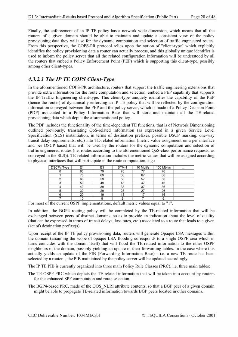
There are two obstacles to the above-mentioned approach to IP-traffic engineering.
First, it is required that the ECMP load balancing is performed based on the route bandwidths determined by the solution to the optimisation problem. Some type of weighted round robin schedulers can achieve this requirement fairly easily, if packets are allowed to arrive out of order to the destination. However, if packets-in-order is a requirement, then some kind of hash function on flow identification has to be performed [Tha00], [Hop00]. Therefore the hash function has to be designed based on the determined route bandwidths. This requires either a priori knowledge of related statistics, or the development of sophisticated hash functions. In addition, is should be ensured that the hash mechanisms employed at each router are consistent. In fact, placing the restriction that load balancing should be achieved by splitting the load equally renders the OSPF approach sub-optimal [For00].
Second, even assuming the ECMP capability and the availability of appropriate hash functions, the inclusion of QoS constraints other than bandwidth in the above formulation places strict constraints on the IP-based approach. Consider for example placing hop-constraints on the traffic trunk routes. In the example in , if the links have capacity 1, the only possible solution for the traffic load brought by trunks A and B is the one shown. Of course, this can be achieved with the IP-approach by defining appropriately the link costs so that the costs of paths (4, 5, 6) and (4, 6) are the same, and by routing explicitly Trunks A and B on the paths shown. However, this is in effect the MPLS approach. In the general case, specifying routes in this manner will cause more overhead than the MPLS approach, since routing will be based on flow ids IDs rather than label switching.
CEC Deliverable Number: 103/IMEC/b1 TEQUILA Consortium - October 2001
D1.3: Intermediate-Results based Protocol and Algorithm Specification (Public Part) Page 26 of 48
Trunk A
Trunk B
•Trunk A: max hop-count 3, bandwidth 1•Trunk B: max hop-count 3, bandwidth 1•All link capacities are equal to 1
1
2
4
5
36
Figure 11: An example of traffic trunk routing
While the discussion above shows that the IP-based approach may require complicated ECMP load balancing and can be sub-optimal in certain cases, it has the advantage that it is readily implementable based on the widely available OSPF protocol and it scales better than MPLS. Moreover, studies have shown [For00] that in certain networks the performance of the IP-based approach with simple ECMP load balancing is not far from the MPLS approach [For00]. If the proposed QoS related extensions to OSPF are implemented [Apo98], then some of the above-mentioned issues may be resolved.
In the model we consider in this work, we have to also take into account the traffic trunk hose model. As discussed above, bandwidth efficiency can be achieved in such a model if with each traffic hose there is at least one associated tree containing all the egress nodes of the hose, and having as source the hose ingress node. With the IP-approach, the tree associated with the defined traffic hoses can be naturally defined as follows. Once the link weights have been defined, the shortest path tree, , from an ingress node to all egress nodes can be defined. For each of the traffic hoses entering the network from the given ingress node, the associated tree is the sub-tree of that contains all the egress nodes of the hose. Having defined the hose trees, the link loads can now be determined and the system cost function can be calculated. A heuristic using some of the ideas in [For00] is then used to modify the link costs in such a manner so that the system cost is improved. The heuristic is in effect a local search technique, whereby the links whose weights are modified are the links which emanate from the same node as the link with the largest cost function.
iSi
iS
The algorithm is applied successively for each of the PHBs defined in the system. Hence, for each of the defined PHBs, different weights are assigned on each link. These weights are downloaded to the routers and are used to populate the forwarding tables, one for each of the defined PHBs. In addition, the algorithm provides the link bandwidth allocated to each of the PHBs. This information is downloaded to Dynamic Resource Management which configures the routers.
4.3.2.2 Overview The Internet is a collection of IP networks that are organized into autonomous systems (AS), where an AS is a domain that is managed by a fully identified administrative entity, which is in charge of managing the routers and the transmission resources of such domains, and is also responsible for the definition of the routing policies that will be enforced by the routers of the AS, by means of the activation of dynamic routing protocols.
CEC Deliverable Number: 103/IMEC/b1 TEQUILA Consortium - October 2001
D1.3: Intermediate-Results based Protocol and Algorithm Specification (Public Part) Page 27 of 48
From this very generic perspective, IP traffic engineering should at least rely upon the (possibly enhanced) characteristics of existing IP routing protocols exclusively, not only because there are many regions of the Internet where routers are not MPLS-enabled, but also because an IP traffic engineering policy should be largely inspired by the routing policies that are enforced within domains (by means of activating protocols such as OSPF and IS-IS) and between domains, as far as the network reachability information that is conveyed by the BGP4 protocol is concerned. It is therefore a primary goal of the TEQUILA project to fully benefit from the implicit traffic engineering capabilities of these routing protocols.
The IP traffic engineering approach of the TEQUILA system basically relies upon:
• The activation of the Open Shortest Path First (OSPF) protocol within the domain. In addition to the basic features of this link state protocol, it is assumed that most of (if not all) of the OSPF routers will have the capability to generate opaque Link State Advertisement (LSA) messages that will be used to convey traffic engineering-related information within the domain, so that the Shortest Path First (SPF) algorithm takes this information into account for the dynamic computation of traffic engineered routes,
• The activation of the Border Gateway Protocol, version 4 (BGP4) to exchange network reachability information between domains. In addition to the basic features of this path vector routing protocol, a specific attribute has been specified to convey traffic engineering-related information between domains, so that the BGP4 route selection process might be influenced by this information accordingly,
• A global scheme for providing routers with the appropriate traffic engineering-related information, so that a global IP traffic engineering policy might be enforced accordingly. While there are several protocol candidates to convey the traffic engineering-related information (namely a Command Line Interface (CLI) kind of language, the Simple Network Management Protocol (SNMP) or the Common Open Policy Service Protocol (COPS), this scheme is based upon the use of the Common Open Policy Service (COPS) protocol that will be used in Provisioning mode (COPS-PR). The choice of this protocol has been motivated by the following reasons:
The dynamic enforcement of an IP traffic engineering policy relies upon specific configuration information that will be used by the routers to compute and select the traffic engineered routes which will comply with the QoS requirements that have been expressed by a customer towards a provider, and that have been dynamically negotiated between both parties. This configuration information (which can be expressed in terms of DiffServ Code Point (DSCP) encoding, metric value assignment on a per interface and per DSCP basis, Per Hop Behaviour configuration information) is by definition very sensitive, and it therefore requires to be conveyed over a reliable transport mode. As such, COPS-PR relies upon the establishment of a Transmission Control Protocol (TCP) connection between the routers and the server that will dynamically store, maintain and update the IP TE policy provisioning data,
Furthermore, the introduction of a high level of automation in the actual provisioning of IP TE policy data implies the use of a stateful protocol that will provide the appropriate dynamics, hence alleviating the need of complex configuration tasks for the network managers. From this perspective, the COPS-PR machinery relies upon request and decision states which are shared between the routers and the policy server, and it allows the policy server to push configuration information towards the routers,
It is also required that the IP TE policy server might be able to send unsolicited decision messages towards the routers, whenever there are changes in the definition of the IP TE policy (modification of metric values on a per-DSCP basis, for example). From this perspective, the COPS-PR protocol is the only protocol that supports that kind of capability amongst the aforementioned candidate protocols,
CEC Deliverable Number: 103/IMEC/b1 TEQUILA Consortium - October 2001
D1.3: Intermediate-Results based Protocol and Algorithm Specification (Public Part) Page 28 of 48
Finally, the enforcement of an IP TE policy has a network wide dimension, which means that all the routers of a given domain should be able to maintain and update a consistent view of the policy provisioning data they will use for the dynamic computation and selection of traffic engineered routes. From this perspective, the COPS-PR protocol relies upon the notion of "client-type" which explicitly identifies the policy provisioning data a router can actually process, and this globally unique identifier is used to inform the policy server that all the related configuration information will be understood by all the routers that embed a Policy Enforcement Point (PEP) which is supporting this client-type, possibly among other client-types.
4.3.2.3 The IP TE COPS Client-Type In the aforementioned COPS-PR architecture, routers that support the traffic engineering extensions that provide extra information for the route computation and selection, embed a PEP capability that supports the IP Traffic Engineering client-type. This client-type uniquely identifies the capability of the PEP (hence the router) of dynamically enforcing an IP TE policy that will be reflected by the configuration information conveyed between the PEP and the policy server, which is made of a Policy Decision Point (PDP) associated to a Policy Information Base that will store and maintain all the TE-related provisioning data which depict the aforementioned policy.
The PDP includes the functionality of the time-dependent TE functions, that is of Network Dimensioning outlined previously, translating QoS-related information (as expressed in a given Service Level Specification (SLS) instantiation, in terms of destination prefixes, possible DSCP marking, one-way transit delay requirements, etc.) into TE-related information (metric value assignment on a per interface and per DSCP basis) that will be used by the routers for the dynamic computation and selection of traffic engineered routes (i.e. routes according to the aforementioned QoS-class performance requests, as conveyed in the SLS)). TE-related information includes the metric values that will be assigned according to physical interfaces that will participate in the route computation, e.g.:
For most of the current OSPF implementations, default metric values equal to "1".
In addition, the BGP4 routing policy will be completed by the TE-related information that will be exchanged between peers of distinct domains, so as to provide an indication about the level of quality (that can be expressed in terms of transit delays, loss rates, etc.) associated to a route that leads to a given (set of) destination prefixe(s).
Upon receipt of the IP TE policy provisioning data, routers will generate Opaque LSA messages within the domain (assuming the scope of opaque LSA flooding corresponds to a single OSPF area which in turns coincides with the domain itself) that will flood the TE-related information to the other OSPF neighbours of the domain, possibly yielding an update of their forwarding tables. In the case where this actually yields an update of the FIB (Forwarding Information Base) - i.e. a new TE route has been selected by a router -, the PIB maintained by the policy server will be updated accordingly.
The IP TE PIB is currently organized into three main Policy Rule Classes (PRC), i.e. three main tables:
The TE-OSPF PRC which depicts the TE-related information that will be taken into account by routers for the enhanced SPF computation and route selection,
The BGP4-based PRC, made of the QOS_NLRI attribute contents, so that a BGP peer of a given domain might be able to propagate TE-related information towards BGP peers located in other domains,
CEC Deliverable Number: 103/IMEC/b1 TEQUILA Consortium - October 2001
D1.3: Intermediate-Results based Protocol and Algorithm Specification (Public Part) Page 29 of 48
The TE route information PRC, which is made of the TE routes that have been selected by the routers for conveying traffic according to a level of quality that has been depicted in a (set of) SLS instances. This table therefore ensures the overall consistency between what's actually stored in the routers and the policy server.
4.3.2.4 OSPF Extensions The traffic engineering extensions of the OSPF protocol that are taken into account by the routers basically consist of two main TLV - the router (for identification purposes) TLV and the link TLV. The Link TLV itself contains a collection of sub-TLV that aim at depicting different kinds of TE-related information - namely, a TE metric (that could be assigned on a per interface basis), as well as information related to the bandwidth of a transmission link an OSPF participating interface is attached to - the maximum bandwidth that is available (e.g. the physical capacity of the link), the amount of reservable bandwidth, the amount of (currently) unreserved bandwidth, etc.
4.3.3 Inter-domain TE Issues Providing end-to-end quality of service is probably one of the most important challenges of the Internet, not only because of the massive development of value-added IP service offerings, but also because of the various QoS policies that are currently deployed and enforced within an autonomous system, and which may well differ from one AS (Autonomous System) to another.
For almost the last decade, value-added IP service offerings have been deployed over the Internet, thus yielding a dramatic development of the specification effort, as far as quality of service in IP networks is concerned. Nevertheless, providing end-to-end quality of service by crossing administrative domains still remains an issue, mainly because:
QoS policies may dramatically differ from one service provider to another,
The enforcement of a specific QoS policy may also differ from one domain to another, although the definition of a set of basic and common quality of service indicators may be shared between the service providers.
Activate the BGP4 protocol for exchanging reachability information between autonomous systems has been a must for many years, and, from this standpoint, the BGP4 protocol appears to be a privileged vector for conveying information related to the enforcement of end-to-end QoS policies.
The TEQUILA approach consists in conveying this indication in a specific BGP4 attribute, named the QOS_NLRI attribute, which will be transmitted in BGP UPDATE messages. The contents of this attribute can be valued according to basic policies that consist in redistributing the OSPF-based TE routes into BGP, hence providing some hints about the time to reach a prefix destination located in the AS from where the corresponding route is announced to the outside world, for example.
The QOS_NLRI attribute is structured in a way that systematically associates a destination prefix to a (set of) QoS information, so that the BGP route selection process can be influenced accordingly. Therefore, a given BGP peer will have the ability to announce routes that are QoS specific, hence the selection of traffic engineered paths across domains. As an example, the matching conditions expressed in the QOS_NLRI attribute can provide the following indication:
• "Route to network N1 experiences a 120 ms one-way transit delay".
• "Route to network N2 is appropriate for EF-marked datagrams".
CEC Deliverable Number: 103/IMEC/b1 TEQUILA Consortium - October 2001
D1.3: Intermediate-Results based Protocol and Algorithm Specification (Public Part) Page 30 of 48
4.4 Dynamic Route Management
4.4.1 MPLS-based Approach In the MPLS approach, the Dynamic Route Management (DRtM) component is a distributed component located at the edge routers, responsible for managing the routing processes in the network according to the guidelines provided by Network Dimensioning. This amounts to:
• Setting up traffic forwarding parameters at the ingress node, so that incoming traffic is routed to LSPs according to the bandwidth determined by Network Dimensioning.
• Modifying the routing of traffic according to feedback received from Network Monitoring
• Issuing alarms/warnings to Network Dimensioning in case available capacity cannot be found to accommodate new connection requests
During initialization, Network Dimensioning provides DRtM the set of (hose) traffic trunks, T which are to be managed with DRtM. The common characteristic of this set of traffic trunks is that they all have as ingress node the node for which the given DRtM is responsible. With each traffic trunk T∈T the following information is provided:
• The set of trees to which traffic belonging to TS T is to be routed, as well as the bandwidth of each of these trees (the bandwidth of a tree is the bandwidth allocated to each of the links of the tree).
• The PHB treatment of traffic belonging to T
• The end-to-end delay and loss probability (upper bound) of traffic belonging to T
DRtM also requests from Network Monitoring statistics about the load incurred by various groups of "addresses". This statistical information is used by DRtM to allocate address groups to each of the traffic trunk trees, according to the bandwidth assigned to these trees. Based on this allocation, the LSP forwarding table at the ingress router is populated.
During system operation Network Monitoring informs DRtM about the QoS performance (end-to-end delay, loss probability and used bandwidth) of the traffic routed through the LSPs managed by DRtM. In addition, Network Monitoring informs DRtM about the QoS performance of the network PHBs used by the managed LSPs.
The monitoring of PHB QoS performance is used by DRtM to take proactive measures. Specifically, DRtM may avoid routing traffic to LSPs using the PHBs whose QoS performance in terms of delay and loss probability becomes critical, even though end-to-end performance deterioration on these LSPs may not have been observed. Hence actions at this stage attempt to avoid the deterioration of end-to-end QoS metrics and in addition help in relieving the load on the congested PHB.
The monitoring of LSP QoS performance is used by DRtM to take reactive measures. Specifically, DRtM will avoid traffic routing on LSPs whose QoS performance is already critical. However, some end-to-end QoS performance deterioration may have occurred at this point.
Based on the information received by Network Monitoring, DRtM may reassign some of the address groups to the various managed trees and hence update the LSP forwarding table at the ingress router. During this process, mechanisms are employed to ensure that during reassignment the packets-in-order condition is satisfied. If appropriate LSPs for the reassignment cannot be found, DRtM issues alarms to Network Dimensioning, which in turn may take more global actions in order to relieve the congestion.
CEC Deliverable Number: 103/IMEC/b1 TEQUILA Consortium - October 2001
D1.3: Intermediate-Results based Protocol and Algorithm Specification (Public Part) Page 31 of 48
4.4.2 IP-based Approach The DRtM component in the IP-based TE approach is centralized and much closer tied-up to ND. Its main objective is to update link metrics during the on-line system operation in order to adjust to traffic fluctuations. Since a small change in the weight of a link may lead to a large number of route changes and hence to a large amount of load shifting at various parts of the network, it is required that DRtM has a global network view. This is the reason we chose to implement DRtM as a centralized component.
The deployment of load-sensitive change of the link metrics is hampered by the overhead imposed by the link-state update propagation, leading to significant route flapping, since paths are selected based on “out-of-date” information. In some cases it is possible to overcome this problem, by updating the costs only for long-lived flows [Shai99]. Though this approach works well, it has the drawback that it is very difficult to draw the line between long- and short-lived flows; in addition, it requires the use of pre-computed paths (e.g. LSPs) for the short-lived flows. Our main research concern on this issue of dynamically adjusting the link costs is on the definition of heuristics that, based on thresholds on link loads, drive to route adjustments without causing excessive route flapping. This work is still ongoing and it is mainly based on experimentation.
4.5 Dynamic Resource Management One of the requirements of QoS provisioning is a means for logically or physically partitioning network resources so that different traffic types do not interfere to the extent that they degrade the performance of each other. Resource partitioning, on the other hand, may mean that the network is inefficiently utilized if the width of the allocated partitions is not in accordance with the requirements of the actual load. In this case, resources allocated to one traffic type may exceed demand while insufficient resources are available for another traffic type where the allocated resources have been underestimated. This may result in higher than expected blocking or dropping rates for the other traffic types, which impacts their performance, and hence the delivered QoS. For this reason it is desirable to dynamically manage resource partitioning.
Dynamic Resource Management (DRsM) has distributed functionality, with an instance attached to each router. In both MPLS and IP TE approaches, it aims at ensuring that link capacity is appropriately distributed between the PHBs sharing a link by appropriately setting buffer and scheduling parameters according to ND directives, constraints and rules. Specifically, DRsM receives estimates of required resources for each PHB in terms of minimum and maximum bandwidth to be allocated to that PHB, a minimum bandwidth to be allocated in time of congestion (competition from the other PHBs) together with the maximum delay and packet drop probability to be experienced by packets using that PHB. Through these parameters ND specifies an acceptable operational range for the PHB's bandwidth, which has been calculated, based on the traffic forecasts it has received from the SLS Management system. Within the bounds of this margin, DRsM is free to dynamically manage resource reservations (i.e., the effective resources required to cope with unexpected SLS invocations, for example). Compared to ND, DRsM operates on a relatively short time-scale (order of minutes).
DRsM triggers ND when network/traffic conditions are such that its algorithms are no longer able to operate effectively, e.g. due to excessive high priority traffic, link partitioning is causing lower priority/best effort traffic to be throttled. DRsM may issue over- or under-load alarms to ND respectively if the higher margin is closely approached, or if the PHB's rate has been below the lower margin for a predetermined time.
In its simplest form the DRsM is responsible for tracking the utilization of a PHB through the services of a Monitoring system, which is capable of issuing alarms when defined thresholds on PHB rate have been crossed. When lower thresholds are crossed, Monitoring triggers DRsM and the PHB is considered to be under-utilized. DRsM should reduce the allocated bandwidth to allow other PHBs to be allocated additional link resources should they require them. If the PHB is overloaded and the upper threshold has been crossed then the bandwidth should be increased if sufficient link capacity is available.
CEC Deliverable Number: 103/IMEC/b1 TEQUILA Consortium - October 2001
D1.3: Intermediate-Results based Protocol and Algorithm Specification (Public Part) Page 32 of 48
While this illustrates the role of DRsM in managing a single PHB/queue, the complete task of DRsM is to manage the resources of all the PHBs defined on a link by distributing bandwidth and buffer space among them. DRsM distributes spare link capacity between the PHBs when the sum of the demands is less than the link capacity. When the sum of the demands is greater than the link capacity DRsM will allocate the minimum congestion bandwidth to each PHB and distribute the remaining link capacity in proportion to the demands of each PHB.
4.6 Summary In this section we addressed the Traffic Engineering aspects of the TEQUILA architecture. We considered first Network Dimensioning, which starts from the traffic matrix produced from Traffic Forecast and produces network configurations and routing strategies to deal with the expected traffic demand in MPLS and IP-based networks. We detailed both the objectives of the optimisation problem and the top-level algorithmic approach. A detailed overview of the IP TE approach was included. We then discussed Dynamic Route Management issues for both MPLS and IP and then Dynamic Resource Management issues that are common in both the MPLS and IP approaches. A key aspect of the Traffic Engineering subsystem is its scalability due to the fact that is only aware of a limited number of QoS classes instead of individual SLSs.
CEC Deliverable Number: 103/IMEC/b1 TEQUILA Consortium - October 2001
D1.3: Intermediate-Results based Protocol and Algorithm Specification (Public Part) Page 33 of 48
5 MONITORING AND MEASUREMENT ARCHITECTURE
5.1 Introduction Monitoring and measurement architectures are becoming increasingly important for providing QoS and service assurance. The Internet has been delivering single class best-effort IP service without traffic and performance guarantees. The measurement functions in current best-effort networks mostly have a diagnostic role. They evaluate the current status of the network, or analyse the network behaviour during a certain time period, and report their findings to a management system. The measurement information is normally collected per-traffic flow basis for accounting and per-link basis mainly for diagnostic purposes. When adding traffic engineering to the network, the algorithms used will need an overview of the network status for their dynamic reactions. The measurement functionality that delivers this status is viewed as operational measurements.
Traffic forwarded in QoS-enabled networks (i.e. IP networks that are composed of DiffServ-capable routers that process traffic according to a QoS policy) might encounter a differentiation into several service types/classes. As the network attempts to offer several service types (e.g., real-time, best-effort services, etc. [D1.1]) by employing traffic engineering mechanisms, service monitoring is becoming increasingly important for providing end-to-end QoS and service assurance. Therefore, monitoring no longer has only diagnostic role but also it turns into an important tool for assisting the network operation and providing service auditing for both traditional and value-added services. In addition, traffic belonging to each service type has certain requirements and exhibits certain behaviour. Having only a single measurement result is not adequate for explaining all traffic belonging to different service types. It should be noted that, in best-effort networks, a single measurement (e.g., round-trip/one-way delay) is performed between a given source-destination pair irrespective of different traffic flows sent between these end-points. Therefore in QoS-enabled networks, measurement information needs to be collected in finer granularity e.g., per service type.
The monitoring part of this document is organised as follows. Section 5.2 describes some requirements that need to be taken into account when developing a monitoring architecture for use in traffic engineered IP networks. Section 5.3 briefly describes the monitoring and measurement requirements in TEQUILA. Monitoring and measurement architecture designed within the context of the TEQUILA project, the monitoring components and their relationship with other functional components are explained in section 5.4. In section 5.5, it is proposed how the measurements at the node, network, and service levels should be performed. Section 5.5.3 specifies the monitoring feedback required by other components of TEQUILA system. Section 5.6 explains the scalability issues for such an architecture. Section 5.7 concludes and addresses the ongoing work of monitoring and measurement in TEQUILA.
5.2 Monitoring Requirements for Traffic-Engineered Networks and Customer Services
Traffic engineering is achieved through capacity and routing management [PRIN-TE]. These two are realised with the calculation, selection and installation of a set of routes and queue management parameters, throughout the network in order to accommodate as many customer requests as possible, while at the same time satisfying their QoS requirements and optimising the use of network resources. The traffic engineering functions require observing the state of the network through a monitoring system and applying control actions to drive the network to a desired state. This can be accomplished reactively by taking actions in response to the current state of the network, or pro-actively by using forecasting techniques to anticipate future trends and applying action to prevent any undesirable future conditions. Hybrid reactive and proactive approaches are also possible. Ideally, control actions should involve the modification of: traffic management parameters, parameters associated with routing, and constraints associated with resources [RFC 2702].
CEC Deliverable Number: 103/IMEC/b1 TEQUILA Consortium - October 2001
D1.3: Intermediate-Results based Protocol and Algorithm Specification (Public Part) Page 34 of 48
Monitoring and measurement determines the operational state of a network and can assist the traffic engineering algorithms in the optimisation and dimensioning of the network by providing feedback data about the status of network resources. This data can be used by traffic engineering mechanisms to automatically react and adaptively optimise network performance. Consequently, monitoring not only has diagnostic role but also it has pro-active/reactive operational role. In addition, measurement can also provide information about the resource usage and the quality of offered services. As a result, monitoring architecture should provide information for:
• Assisting traffic engineering in allocating resources (e.g., to queues and paths over which routes will be established) efficiently and effectively. The capability to obtain statistics at the QoS-enabled route level is so important that it should be considered an essential requirement for traffic engineering.
• Assisting traffic engineering in dimensioning the network for any short or long term changes required in the network configuration set-up. This is extremely helpful for pro-active control of the network.
• Verifying whether the QoS performance guarantees (negotiated between a customer and a provider) committed in Service Level Specifications (SLSs) is in fact being met. This requires an in-service verification of traffic and performance characteristics per customer service. SLS is a set of technical parameters and their values, which together define the service, offered to a traffic stream by a DiffServ domain. SLSs can differ depending on the type of services offered and different SLS types have different QoS indicators that require processing of different types of information [TEQ-SLS], [SLS-FRAME].
5.3 Monitoring & Measurement Requirements in TEQUILA In TEQUILA, the following parts and components are interested in the measurement information:
• The SLS Management part including: • Traffic Forecast for optimising the forecasted traffic related to SLS instances as a basis for long-
term network configuration. Monitoring is also to provide analysed traffic and performance information for long-term planning in order to optimise the network and to avoid undesirable network conditions. The analysed information might include traffic growth patterns and congestion issues.
• SLS Invocation that may use current SLS loads for SLS admission control of new flows. • The Traffic Engineering part including:
• ND for calculating a new dimensioning of the resources if any part of the network is not able to meet performance objectives.
• DRtM for taking appropriate engineering actions on setting up new routes, modifying existing routes, load-balancing among routes, and re-routing of traffic for optimisation purposes or work around congestion.
• DRsM for performing node-level optimisations on resource reservations (bandwidth assignment and buffer management) to combat localised congestion. It should be noted that Traffic Engineering components operate in different time scales ranging from weeks through days for ND, or hours through minutes for DRtM, and minutes through seconds for DRsM.
• Policy Management part for getting notifications, triggering events which signal the enforcement of specific policies, or the inability to enforce a policy (policy run-time conflicts) which trigger alarms to the administrator.
• The SLS Monitoring component of the Monitoring part for monitoring the continuity and quality of services, auditing services, and reporting.
5.4 TEQUILA's Monitoring & Measurement Architecture The monitoring architecture of TEQUILA includes the following components:
1. Node Monitoring (NodeMon) responsible for node related measurements
CEC Deliverable Number: 103/IMEC/b1 TEQUILA Consortium - October 2001
D1.3: Intermediate-Results based Protocol and Algorithm Specification (Public Part) Page 35 of 48
2. Network Monitoring (NetMon) responsible for edge-to-edge performance monitoring and any required network-wide post-processing based on statistical functions
3. SLS Monitoring (SLSMon) responsible for customer related service monitoring
4. Monitoring Repository (MonRep) for storing configuration information and measurement data
5. Monitoring GUI (MonGUI) for displaying measurement results.
TEQUILA's Monitoring part, its components, interfaces to other components, the interface technologies and protocols are shown in Figure 12. The next sections explain the monitoring components and their functions.
PolicyMgt.
Monitoring Part in TEQUILAMonitoring Part in TEQUILA
DRsMDRsM
IP-TEMIP-TEM
Traffic Engineering
NetMon &NodeMon
NetMon &NodeMon
NodeMon
Node Monitoring
Node Node MonitoringMonitoring
Node Monitoring
Node Node MonitoringMonitoring
Node Monitoring
Node Node MonitoringMonitoring
Network MonitoringNetwork Network
MonitoringMonitoring
SLS Monitoring
SLS SLS MonitoringMonitoring
MonitoringMonitoringGUIGUI
CORBA interface
Human Interface
NodeMons
SLSMon
Data-basefor
MonRep
Data-basefor
MonRep
Inte
rfac
esIn
terf
aces
Monitoring Monitoring RepositoryRepository
NetMon
SLS Mgt.Including
TF & SLS Repository
SLSMon
TEQUILATEQUILAPartsParts
Data PlaneData Plane
DataTransmission
Path
Generic ALSNMP/etc.
SQL
CORBA
MPLSND/DRtM
MPLSND/DRtM
Ingress/Egress Router
CoreRouter
Ingress/Egress Router
Figure 12: TEQUILA Monitoring Architecture and its interactions with other parts.
In general, the monitoring functions are split into four phases:
Request: Every component that requires monitoring information must register to one of the NodeMon, NetMon, or SLSMon requesting monitoring actions by indicating what measurement data it wants to be notified about.
Configuration: NetMon will decide which NodeMons are needed to be at the basis of any measurements and it configures them. SLSMon performs some configurations on NodeMons located at ingress/egress points.
Execution: NodeMons perform the measurements on basis of these configurations. Other available data such as metering information may also be used. NodeMons also perform some basic measurement processing. NetMon/SLSMon will further aggregate and process NodeMon measurements if it is necessary.
Reporting and exception: The analysed measured data and events are sent back to the registered components.
CEC Deliverable Number: 103/IMEC/b1 TEQUILA Consortium - October 2001
D1.3: Intermediate-Results based Protocol and Algorithm Specification (Public Part) Page 36 of 48
5.4.1 Node Monitoring A diverse variety of measurement data is needed in order to perform network and customer service performance and traffic monitoring. The variety of data, the necessary processing and the magnitude of the raw data make a distributed data collection system more practical. Processing and aggregating the raw data into accurate and reliable statistics and reducing the amount of data near its source in order to transmit the data efficiently to the components of the system is key to automating the dynamic operation of the network. Hence, the Node Monitoring is distributed across the network i.e., one per Network Element (NE).
NodeMon allows other components to request monitoring and measurement actions. NodeMon includes the following functions: Configuration and Monitoring function handles registration requests and initiates measurements on NEs for both diagnostic and operational monitoring and sets thresholds. NodeMons receives the configuration information with entries that each defines a variable, polling/sampling period, and threshold parameters. A local Data Collector (Reader) collects measurement results from either meters/probes located at NEs or active monitoring agents. A probe is a generic term for a dedicated machine or a software agent that measures data moving through the network or injects test traffic in the stream to take its measurements. Probes present the data they collect in a variety of ways. The job of data collector is to regularise and re-abstracts various types of measured data in a structural way. A Local Performance Analyser performs some short-term basic evaluation of results such as averaging. It also performs threshold crossing detection and notification. The process data is passed to the components and it is also stored in the monitoring data store (part of MonRep).
5.4.2 Network Monitoring Network Monitoring is in general, centralised and it utilises network-wide information collected by NodeMons. NetMon instructs the NodeMons to measure the performance and traffic parameters and builds a physical and logical network view (i.e., the view of the routes that have been established over the network) based on measurement information collected for links, nodes, PHBs, and route statistics. NetMon includes the following functions: Configuration and Monitoring function handles monitoring registration requests and configures the NodeMons including threshold setting. NetMon needs to know the network logical configuration, which changes as the ND re-dimensions the network or DRtM re-routes the traffic to alleviate congestion. Data Collector accesses MonRep to get measurement data and may notify other components about threshold crossing detected by NodeMons if necessary. Performance Analyser aggregates and performs longer-term in-depth statistical analysis on measurement data including trend analysis. The data produced by such analysis is stored in the monitoring repository and the appropriate processed data is forwarded to the interested components. NodeMon and NetMon functions and their interactions are shown in Figure 13.
CEC Deliverable Number: 103/IMEC/b1 TEQUILA Consortium - October 2001
D1.3: Intermediate-Results based Protocol and Algorithm Specification (Public Part) Page 37 of 48
Network Monitoring:Measurement Configuration and Initiation, Data Collector
Performance AnalyserPerformance Analyser(Trend Analysis, Library of statistical functions)
Mon
itori
ngM
onito
ring
Rep
osito
ryR
epos
itory Ev
ents
& st
atis
tics
Figure 13: Node and Network Monitoring functions and interactions.
5.4.3 SLS Monitoring SLS Monitoring is centralised, since it must keep track of the compliance of the level of service provided to the customer SLS instances, by analysing information provided by NetMon and ingress/egress NodeMons. SLSMon functions and its interactions with external components are shown in Figure 14. SLS Management notifies SLSMon and requests the creation of any necessary monitor instances when an SLS is invoked. SLSMon acts as a client to NodeMons and NetMon. The NetMon provides the end-to-end performance view for SLSMon via MonRep. It is also essential for SLSMon to use the edge node customer related accounting statistics via ingress/egress NodeMons. SLSMon retrieves SLS related information from SLS repository. When a SLS is invoked, a specific route will be used for the traffic related to this SLS. SLSMon needs to receive performance-related information (one-way delay and loss on this specific route from NetMon and traffic-related information (throughput) specific to this SLS from ingress/egress NodeMon. It should be noted that NetMon process the scope of this SLS and if it already instructed the ingress/egress NodeMons to measure one-way delay and loss on this route/LSP, it doesn't reissue the monitoring request but it uses measurement information available in the MonRep.
CEC Deliverable Number: 103/IMEC/b1 TEQUILA Consortium - October 2001
D1.3: Intermediate-Results based Protocol and Algorithm Specification (Public Part) Page 38 of 48
SLSMon includes the following functions as shown in Figure 14: Configuration and Monitoring function handles activation/deactivation process issued by SLS Subscription/Invocation, configures and activates the ingress/egress NodeMons by accessing to the SLS repository. A Data Collector accesses MonRep for measurement results collected by ingress/egress NodeMons and NetMon and combines the data for each individual SLS. Each contracted SLS's performance and traffic related values are checked against measurement data through a Contract Checker of SLS Manager to determine whether any violations occur and then generate reports. SLS Manager is also responsible to activate the Report Generator. Necessary Reports are provided to both the customer and the management. The measured service level values and the result from Contract Checker are stored in the MonRep. It should be noted that in the case of hose model [D1.1], monitoring performs measurements (e.g., one-way delay) between hose ingress and each of its egress nodes. It is SLSMon task to get these individual measurements and find e.g., the worse case of these one-way delays as the one-way delay experienced by the hose.
Activation/Deactivation
SLS MonitoringSLS Monitoring
Action tobe taken6
SLSSubscription/
Invocation
SLSRepository
Data Collector & Aggregator
SLS Manager Including
Contract CheckerManagement Report
Customer ReportReport Generator
TrafficForecast
Configuration & Monitoring1
2
3 4
7
9
10
11
12
13
14
I/E Node MonitoringI/E Node I/E Node
MonitoringMonitoringNetwork
MonitoringNetwork Network
MonitoringMonitoring
SLSMonStore
Monitoring Repository
NodeMon/NetMon Store
Arrows show the request/data flow and numbers show the order of tasks.
8
5
QueryData
Figure 14: SLS Monitoring functions and interactions.
5.4.4 Monitoring Repository and Monitoring GUI The MonRep consists of two major parts for data cataloguing, a "data store" having a database functionality for storing the possibly large amounts of data for monitoring components and an "information store" for storing smaller amounts of configuration type information. Measurement data is stored in a "data store" for possible later analysis via the GUI, or performance analysers. Information about active monitoring processes together with any other required configuration information is stored in the monitoring "information store".
MonGUI presents a user interface allowing human operators to request graphical views of monitoring statistics extracted from the monitoring data store. It also exposes an interface to allow other components to request display of statistics. MonGUI might be used in a Network Operations Centre.
CEC Deliverable Number: 103/IMEC/b1 TEQUILA Consortium - October 2001
D1.3: Intermediate-Results based Protocol and Algorithm Specification (Public Part) Page 39 of 48
5.5 Node, Network, & Service Level Measurements
5.5.1 Measurement Methods and Measurement Data Typically for a monitoring architecture, there are two types of methods to perform measurements. Active measurements inject test traffic into networks based on a scheduled sampling in order to observe network behaviour. Normally, active measurement tools require co-operation from both end-points of the measurement and they need to have a continuous session as long as the active measurement is required between two nodes. In addition and specifically in the case of measuring one-way delay, both end-points require to be synchronised. Therefore, the deployment of Network Time Protocol (NTP) [RFC 1305], Global Positioning System (GPS) or CDMA receivers for synchronisation of end-points is required. It should be noted that NTP accuracy depends on the network conditions and it could provide poor level of precision. GPS provides high precision but its deployment makes it an expensive solution.
In contrast, passive measurements observe actual traffic without injecting extra traffic into the network. While passive measurement does not require co-operation from end-points, it requires continuous collection of data and must monitor the full load on the link, which can be problematic on high-speed links. In both cases, the quality of analysed information depends on the granularity and integrity of collected data.
Monitoring can occur at different levels of abstraction. Measurements can be used to derive packet level, application level, user/customer level, traffic aggregate level, node level, and network wide level characteristics. In traffic engineered networks, the monitoring occurs at the network layer for deriving all above characteristics except packet and application level characteristics. These include performance related measurements such as one-way delay, one-way packet delay variation (jitter), and one-way packet loss, and traffic related measurements such as the traffic load, and throughput.
5.5.2 Engineering Aspects TEQUILA uses an object-oriented approach for monitoring architecture. The monitoring architecture is realised as a set of Java classes. The monitoring architecture defines a set of CORBA (Common Object Request Broker Architecture) interfaces to internal monitoring components for communicating with one another and to external components. All of the CORBA interfaces are implemented using the Java 2 platform. Measurement results are passed to NodeMons via a Generic Adaptation Layer (GAL), and NEs use COPS (Common Open Policy Service [RFC 2748], [RFC 3084]), SNMP (Simple Network Management Protocol, [RFC 1157]), etc. to communicate with the GAL.
Two types of routers are used in the testbeds: commercial (Cisco) and PC-based (Linux) routers. For passive measurements such as throughput, load and packet discards, MIBs (Management Information Bases), PIBs (Policy Information Bases), and metering information from traffic conditioners (whichever is possible) are used to poll the data. The availability of required passive measurements is limited in commercial routers. Cisco routers collect byte counts for physical network interfaces and virtual interfaces using MIB-2 [RFC 1213]. In Cisco routers, LSPs are represented as logical interfaces or tunnel interfaces at the head-end routers. Therefore, data derived from the ingress router of each LSP has an interface definition in MIB-2 that can be used by ingress/egress NodeMon. Packet forwarding data is available for LSPs at the intermediate routers by using the Command Line Interface (CLI). Linux routers are configured to provide any required per-PHB and per IP route/LSP passive measurements.
Two approaches can be taken for performing performance measurements. The measurements are carried out either between two edge nodes for edge-to-edge measurements or between two neighbouring nodes for hop-by-hop measurements in order to determine the status of the attached links and associated queues, schedulers, etc. In TEQUILA, edge-to-edge and hop-by-hop approaches are used for performing active measurements. Figure 15 shows both approaches and their purposes.
CEC Deliverable Number: 103/IMEC/b1 TEQUILA Consortium - October 2001
D1.3: Intermediate-Results based Protocol and Algorithm Specification (Public Part) Page 40 of 48
Edge-to Edge
Hop-by-HopHop-by-HopPM
AM
IP Route/LSP, SLS scope
(Link, PHB) scope (Link, PHB) scope
AM: Active MeasurementPM: Passive Measurement
Node Node MonitorMonitor
Node Node MonitorMonitor
Node Node MonitorMonitor
AMAM
PM PM
Ingress/Egress Router
CoreRouter
Ingress/Egress Router
Figure 15: Hop-by-Hop and Edge-to-Edge measurements.
Ideally, PHB-based delay measurements must be implemented in NEs, which is not currently available in commercial routers. Hop-by-hop measurements are used to estimate a PHB-based delay. This is a practical approach but at the expense of introducing some inaccuracy. Active test traffic is sent between neighbouring hops for estimating PHB-based delays. This introduces inaccuracy as it includes the test packet processing at the originator including PHB function, packet transmission delay onto the link, propagation delay, and packet processing delay at the next hop. The inaccuracy level is reduced by subtracting some of these fixed delays from the measured value. This hop-by-hop method requires the ability of forcing test packets to pass through particular PHBs, calculating the measurement (e.g., delay) by the test traffic receiver, and sending the result back to the originator. For active measurements, OWDP (One-Way Delay measurement Protocol) protocol [OWDP] can be used with some modifications to measure one-way delay and packet loss either hop-by-hop or edge-to-edge.
5.5.3 Monitoring Feedback to Other TEQUILA Parts In TEQUILA, NodeMons collect information on PHBs and routes. NetMon deduces an end-to-end performance view by analysing PHBs and routes related measurements. Table 3 summarises the events and measurement statistics provided to SLS Monitoring, SLS Management, and Traffic Engineering part.
ND informs the NetMon every time it performs (re-) dimensioning about the current network configuration (i.e., PHBs and routes). During initialisation, DRtM reports to NetMon all the routes, the class of service associated to each route, and the associated PHBs that need to be monitored. While the network is in operational state, monitoring components, DRtM, or DRsM informs ND about occurred events (threshold crossings). This triggers re-dimensioning if the conditions satisfy the policy directives. DRsM receives information about PHBs while DRtM receives information about the PHBs and the routes that are useful for their dynamic operations. DRsM uses PHB QoS performance for managing link bandwidth and buffer space according to its algorithm, which considers the actual measured load as compared to predicted resources. In order to do proper load balancing, DRtM needs to know the traffic performance of the various routes.
CEC Deliverable Number: 103/IMEC/b1 TEQUILA Consortium - October 2001
D1.3: Intermediate-Results based Protocol and Algorithm Specification (Public Part) Page 41 of 48
Events and Measurement Statistics for:
SLS Monitoring (SLS Types & Services1)
Metrics
Measurement
Mechanism & Method
(Active/Passive) Real-time Services
Guarantee
data Services
Olympic Services
(Best-effort)
SLS Mgt.
Traffic Engineering
(ND, DRtM & DRsM)
• Performance Per Route2 Per Route Per Route Per Route Per PHB & Route
• User Traffic Flow Per SLS Per SLS Per SLS Per SLS Per macro-flow
Throughput per SLS/flows at egress Flow-based (P) ✔ ✔ ✔ ✔ ✔ Offered load per SLS/flows at ingress Flow-based (P) 0 0 0 0 ✔
• Network's Workload Per LSP Per PHB & LSP
Throughput per PHB per link COPS-PIB/metering (P) ✔ Throughput per LSP Flow-based (P) ✔ ✔ Packet Discards per PHB per link COPS-PIB/SNMP MIB (P) ✔ Link utilisation In/Out SNMP MIB (P) (Per Link) 0
• Availability Metrics
Link & device availability ICMP (A) ✔
Table 3: Measurement requirements for SLS Monitoring, SLS Management, and Traffic Engineering components.
Performance and traffic information on events and measurement statistics are as follows:
• PHB-based delay/loss crossed an upper threshold or returned to normal (normal threshold). • Route end-to-end delay/loss crossed an upper threshold or returned to normal. • PHB-based bandwidth usage crossed an upper threshold or returned to normal. • PHB-based bandwidth usage over an specified interval using an averaging mechanism • The current throughput of each LSP In addition, any ingress/egress NodeMon also provides to its relevant DRtM, information about offered load by various groups of micro-flows and the bandwidth usage of various groups of micro-flows using a specific route. The monitoring of PHB QoS performance and the above information are used by DRtM to take pro-active actions for re-mapping some of the groups that are mapped to routes (multi-path load balancing), which use critical PHBs. NetMon also provides the "current traffic load on LSPs" to the SLS Invocation. This gives the load of aggregate existing flows on each LSP so that admission decisions can be made on new flows.
SLSMon deduces the customer-related service monitoring by using customer flow and route-related measurements. It combines the statistics listed below and maps them to each individual SLS:
• End-to-end delay and packet loss on routes. • Throughput collected at the egress point related to each customer SLS. • Offered load collected at the ingress point related to each customer SLS.
1 SLS Types and services are explained in [TEQ-SLS]. 2 Route represents either IP shortest path in IP-TE or explicit Path (LSP) in MPLS-TE. 3 ✔ is necessary measurement. 0is desirable and could be a useful measurement. ✖ is unnecessary.
CEC Deliverable Number: 103/IMEC/b1 TEQUILA Consortium - November 2001
D1.3: Intermediate-Results based Protocol and Algorithm Specification (Public Part) Page 42 of 48
It should be noted that throughput is defined as the bits per second at which user-traffic is delivered by the network. The offered load is the user traffic in bits per second that the network is supposed to deliver after applying traffic conditioning functions specified in the SLS. Each SLS might have guaranteed throughput and an absolute bound on loss and delay necessary to deliver an acceptable service. As an example, three parameters might be specified in SLS for packet loss: a maximum loss rate of "L" that is not exceeded for percentages of "P" of intervals of length "T" (e.g., L=0.1, P=99%, T=5 minutes). The throughput and the absolute bounds are verified and checked against the above statistical measurements by the Contract Checker of SLS Monitoring. The SLS-related measurement information is also used by Traffic Forecast. The Traffic Matrix resulted from service mapping and aggregation is used by a Traffic Forecast Algorithm in order to determine an optimised (regression) Traffic Matrix by using SLSMon as well as NetMon information. As it was discussed, collecting SLS and finer-grain macro-level flow-based statistics at every ingress point are required. This could introduce additional overhead for routers. In addition, significant processing power might be required for NodeMons located at ingress/egress points as they need to provide traffic or performance related measurements for macro-flows, routes and PHBs using flow based, IPPM-based, and MIB-based probes whereas core NodeMons only provides active and passive PHB related measurements.
NodeMon notifies the Policy consumer about the specified event to trigger certain policy-based actions on policy enforcement. It also notifies the Policy consumer about a registered event, which indicates inability to enforce a certain policy.
5.6 Scalability of Monitoring Architecture A scalable and easily configurable architecture for performing a wide range of monitoring tasks is required. Monitoring large-scale traffic engineered networks requires mechanisms for data collection, data aggregation, data analysis, and providing feedback results. In addition, a diverse variety of measurement data is needed in order to perform network and customer service performance and traffic monitoring. The amount of measurement data will be increased in QoS-enabled networks where a number of nodes (and queues per node) and a large numbers of routes providing different QoS level service need to be monitored. Hence, the monitoring architecture must be able to scale with the size (in terms of number of routers and importance of the mesh) and the speed (in terms of bandwidth) of the network as it evolves. In order to have a scalable solution for such architecture, we propose the following approaches:
I. Defining the monitoring process granularity In a DiffServ environment, the measurement methodology must be aware of different service types. Traffic engineered networks rely upon the use of classical IP routing protocols for the establishment of IP routes (shortest paths), as well as the use of the Multi-Protocol Label Switching (MPLS) technique [8], for the establishment of Label Switch Paths (LSP) that are expected to comply with the QoS requirements specified by the customers. IP routes/explicit paths allow control over routing of traffic flows requiring specific QoS within a domain. IP engineered routes/LSP tunnels are used to carry aggregate user traffic belonging to several SLSs having similar performance requirements. In addition, traffic engineering algorithms do not need to operate at small scale of individual packets as collecting packet-level micro-flow related statistics would be prohibitively expensive and unnecessary. Instead, observation must be performed over all packets but statistics are gathered at the aggregated macro-flow level. Hence, the monitoring process functions based on the configured classes of service handling of the data streams and the scope of offered services between ingress and egress points. That is, the measurement methodology functions at the level of Per Hub Behaviours (PHB) and traffic-engineered IP routes/LSPs for data gathering.
II. Distributing the data collection system
CEC Deliverable Number: 103/IMEC/b1 TEQUILA Consortium - November 2001
D1.3: Intermediate-Results based Protocol and Algorithm Specification (Public Part) Page 43 of 48
To support the dynamic operation of the network, the monitoring architecture must be able to capture the operational status of the network without degrading network performance and without generating a large amount of data. The variety of data, the magnitude of the raw data and the necessary processing close to the measurement source make a distributed data collection system more practical i.e., one monitoring node per network element. The distributed monitoring nodes must have low impact on the performance of any router involved in monitoring and must have minimal effect on network bandwidth.
III. Minimising the measurement transmission overhead by processing the raw data close to the source
Processing and aggregating the raw data into accurate and reliable statistics and reducing the amount of data near its source in order to transmit the data efficiently to the traffic engineering entities is key to automating the dynamic operation of the network. The monitoring system should provide automatic threshold detection by using notification of events as well as processed measurement information. Therefore, two forms of measurement data can be considered: event notification and statistics:
Events: Event notification method can be employed to reduce a large amount of data frequently passed from monitoring nodes to traffic engineering functional entities. The granularity of event notifications can be defined for PHBs and IP routes/LSPs. Basic raw measurement data is taken in short-time scales from variables in the measurement probes. The measurement data is compared with two previously configured thresholds (the upper mark and the normal mark). If the measurement data is found to cross the upper threshold value, the relevant functional entity is informed. Depending on the measurement time-scales, event notification might be postponed on instantaneous upper threshold crossings until successive/frequent threshold crossings are observed and realised that the problem persisted for a specified time interval. This method is to insure that transient spikes do not contribute to changes unless they occur frequently. Upon event notification on upper threshold crossing, further triggers are not delivered until the measurement data returns to normal when the relevant component is notified. Threshold detection implies real-time asynchronous notification of the events that the traffic engineering algorithms needs to react to these events.
Statistics: The measurement data can be aggregated by monitoring nodes into summarising
statistics in order to have a scalable system. Summarisation is usually done by integrating the measurement data over a pre-specified period. The granularity of summarisation periods must be suitably chosen based on the requirements of the interested management functional entity. The granularity of statistics range from PHB and route level for traffic engineering functions to the aggregated flow levels for customer service monitoring. Statistics should be provided in near real-time.
IV. Using aggregate performance measurements combined with per SLS traffic measurements The granularity of measurements can be related to SLSs since every SLS might not need to be monitored in the same way. Ideally, an SLS belonging to a premium class might need measurement results with higher frequency. Monitoring SLSs at different levels of granularity using different sampling frequencies make the monitoring architecture far more complex. Instead, monitoring every customer SLS is scalable and feasible provided aggregate network performance measurements (e.g., delay, loss, jitter) are used combined with per SLS ingress/egress traffic measurements (e.g., throughput). As several SLSs may use a single IP route/LSP, single performance monitoring action is enough to satisfy the requirement of these SLSs. As an example, injecting test traffic from an ingress point toward an egress point on a specific route for measuring one-way delay can satisfy the requirement of multiple SLSs using this same route.
V. Edge-to-edge vs Hop-by-hop measurements The scope of measurements is an important aspect of monitoring architecture. Two approaches can be taken for performing performance measurements: edge-to-edge and hop-by-hop measurements.
CEC Deliverable Number: 103/IMEC/b1 TEQUILA Consortium - November 2001
D1.3: Intermediate-Results based Protocol and Algorithm Specification (Public Part) Page 44 of 48
Monitoring scalability could be a serious concern with MPLS-TE approach. That is, if a full mesh virtual network is in-place, an order of θ(N2) unidirectional LSPs needs to be monitored where N is the number of ingress nodes. It is even worse that the θ(N2) order for LSPs may not be enough because multiple routes are sometimes used for load sharing or multiple services using different LSPs offered between an ingress-egress pair. In large MPLS networks, monitoring of all LSPs edge-to-edge could affect the reliability of the monitoring system that might not scale well due to the fact of having a huge number of LSPs in the network where each ingress node might need to inject test traffic to its associated routes. In addition, it might not be able to provide timely results too. Hence, LSP monitoring is scalable and feasible if only a number of LSPs are selected for edge-to edge measurements based on some criteria/policy decisions. The edge-to-edge approach provides edge-to-edge measurement results. The hop-by-hop approach might overcome this scalability problem by adding the hop-by-hop results and calculating an edge-to-edge result. As multiple routes may be related to a single PHB by sharing a physical link, a single test traffic sent to quantify the behaviour of a given PHB satisfies the performance monitoring requirements of these routes using that link. This results in significant reduction of test traffic in the network. With the hop-by-hop method, the status of every individual link will be known, but inaccuracy will be introduced due to the non-synchronised individual hop-by-hop measurements and concatenating these discrete measurements to estimate per-route edge-to-edge measurement values. Depending on the type of SLS that has been subscribed by the customers, this method may be appropriate for estimating the performance measurements of routes used for low profile traffic (e.g., best-effort). VI. Controlling the amount of test traffic injected into the network The amount of test traffic generated by active measurements methods will be increased in QoS-enabled networks where several PHBs per node and large numbers of routes need to be monitored. There are the following requirements for test traffic:
1. The test traffic load should be small compared to the load on the connection under test. If not, then the test traffic will affect the performance and the measurement does not show the real environment.
2. The sampling intervals should be small enough to study fluctuations in the performance of the network.
3. As the network changes over time, the amount and type of test traffic should be configurable.
4. The measurements should be randomly distributed to prevent synchronisation of events as described in the IP Performance Metrics (IPPM) recommendation [RFC 2330] by using a pseudo-random Poisson sampling rate.
It should be noted that the first two requirements must be as complementary as possible. That is, smaller time intervals means more test traffic, but more test traffic means a higher load on the network. A trade-off between these two requirements needs to be made. The amount of test traffic (traffic load and packet rate) on each network link, sent to measure one-way delay and packet loss during a specified time interval, will depend on the number of IP routes/LSPs crossing the link (in the case of edge-to-edge measurements), the number PHBs attached to the link interface, the number of different test packet sizes used for route and PHB related measurements, the length of these packets, and the statistical average of sampling intervals used. Practically, the test traffic should not exceed e.g., 1% of the total bandwidth that is available in the network.
CEC Deliverable Number: 103/IMEC/b1 TEQUILA Consortium - November 2001
D1.3: Intermediate-Results based Protocol and Algorithm Specification (Public Part) Page 45 of 48
5.7 Summary Engineering large IP networks introduces fundamental challenges that stem from the dynamic nature of user behaviour. Careful engineering of the network is important, since network dimensioning and routing management have significant implications on resource efficiency and user performance [Awd02]. =We propose a monitoring and measurement architecture for node, traffic-engineered network, and service monitoring. This is aimed at facilitating route calculation and optimisation, user service auditing, and traffic forecasting. We also present scalable methodologies for event monitoring and measurement statistics to be used for network operation and in-service verification of traffic and performance characteristics of offered services. Our on-going work focuses on the TEQUILA system implementation and examines the practical effectiveness of monitoring specifically on traffic engineering algorithms and traffic forecasting in both simulation and testbeds environments. This is to provide the analysis of the measured traffic to interested parties, observe their automatic reactions, and assess their performance. This also enables us to investigate the scalability of the monitoring architecture in real-time data processing and notification of the events and statistics according to the current state of the network.
CEC Deliverable Number: 103/IMEC/b1 TEQUILA Consortium - November 2001
D1.3: Intermediate-Results based Protocol and Algorithm Specification (Public Part) Page 46 of 48
6 REFERENCES [Apo98] G. Apostolopoulos et al. “QoS Routing Mechanisms and OSPF Extensions”, RFC
2676, Experimental, August 1999
[Awd99] D. Awduche et al. “Requirements for Traffic Engineering over MLPS”, RFC 2702, Informational, September 1999
[Awd02] D. Awduche, A. Chiu, A. Elwalid, I. Widjaja, X. Xiao, "Overview and Principles of Internet Traffic Engineering", draft-ietf-tewg-principles-01.txt, Expires April 2002.
[Ber92] D. Bertsekas and R. Gallager, Data Networks, Prentice Hall, 1992
[Blak98] S. Blake et al. “An Architecture for Differentiated Services”, RFC 2475, Informational, December 1998.
[D1.1] D. Goderis (ed.), "Functional Architecture and Top Level Design", TEQUILA Deliverable D1.1, September 2000, available at: http://www.ist-tequila.org/.
[DIFFSERV] S. Blake, D. Black, et al., "An Architecture for Differentiated Services", RFC-2475, Informational, December 1998.
[DIFF-MPLS] P. Trimintzios, I. Andrikopoulos, G. Pavlou, et al., "A Management and Control Architecture for Providing IP Differentiated Services in MPLS-based Networks", IEEE Communications Magazine, vol. 39, No. 5, pp. 80-88, May 2001.
[FRAME-QOS] P. Trimintzios, I. Andrikopoulos, G. Pavlou, et al., "An architectural Framework for Providing QoS in IP Differentiated Services Networks", IM2001, Seattle, WA USA, May 2001, http://www.ist-tequila.org/.
[For00] B. Fortz and M. Thorup, "Internet Traffic Engineering by Optimizing OSPF Weights”, in Proc. IEEE INFOCOM, Israel, March 2000
[Geo01] L. Georgiadis et al. “Lexicographically Optimal Balanced Networks”, to appear in Proc. IEEE INFOCOM, Alaska, April 2001
[Georg99] P. Georgatsos et al. “Technology Interoperation in ATM Networks: the REFORM System”, IEEE Communications, Vol. 37, No. 5, pp. 112-118, IEEE, May 1999
[God01] D. Goderis et al. “Service Level Specification Semantics and Parameters”, Internet draft – work in progress, March 2001, see: www.ist-tequila.org/sls.html
[Hop00] C. Hopps, "Analysis of an Equal -Cost Multi-Path Algorithm," RFC 2992, November 2000
[ID-DS] New Terminology for Diffserv. Dan Grossman (2001); draft-ietf-diffserv-new-terms-04.txt
[ID-SLS] Service Level Specification Semantics and Parameters. <draft-tequila-sls-00.txt> D. Goderis et all (2000). Work in progress: http://www.ist-tequila.org/
[Li98] T. Li and Y. Rekhter, “A Provider Architecture for Differentiated Services and Traffic Engineering (PASTE)”, RFC 2430, Informational, October 1998
[RFC 2328] J. Moy. “OSPF Version 2”, RFC 2328, Standards Track, April 1998
[Nich99] K. Nichols, V. Jacobson and L. Zhang “A Two-bit Differentiated Services Architecture for the Internet”, RFC 2638, Informational, July 1999
[OWDP02] S. Shalunov, B. Teitelbaum, M. Zekauskas, "A One-way Delay Measurement Protocol", Internet Draft, Expires: April 2002, http://www.ietf.org/internet-drafts/draft-ietf-ippm-owdp-03.txt
[PRIN-TE] D. Awduche et al. “Overview and Principles of Internet Traffic Engineering”, Internet Draft, Expires: November 2001, draft-ietf-tewg-principles-00.txt.
CEC Deliverable Number: 103/IMEC/b1 TEQUILA Consortium - November 2001
D1.3: Intermediate-Results based Protocol and Algorithm Specification (Public Part) Page 47 of 48
[RFC 1305] David L. Mills, "Network Time Protocol (Version 3) Specification, Implementation", RFC-1305, March 1992.
[RFC 1157] J. Case, M. Fedor, M. Schoffstall, J. Davin, "A Simple Network Management Protocol (SNMP)", RFC-1157, May 1990.
[RFC 1213] K. McCloghrie, M. Rose, "Management Information Base for Network Management of TCP/IP-based internets: MIB-II ", RFC-1213, March 1991.
[RFC 1633] Integrated Services in the Internet Architecture: an overview R. Braden et al. IETF RFC 1633 (1994)
[RFC 2205] Resource Reservation Protocol – Version 1 Functional Specification R. Braden et al. IETF RFC 2205 (1997)
[RFC 2330] V. Paxson, G. Almes, J. Mahdavi, and M. Mathis, "Framework for IP Performance Metrics", RFC-2330, May 1998.
[RFC 2638] A Two-bit Differentiated Services Architecture for the Internet. K.Nichols, V. Jacobson, L. Zhang (199)
[RFC 2702] D. Awduche, J. Malcolm, J. Agogbua, M. O'Dell, J. McManus, "Requirements for Traffic Engineering Over MPLS", RFC-2702, Informational, September 1999.
[RFC 2474] Definition of the Differentiated Services Field (DS-Field) in the IPv4 and IPv6 Headers", K.Nichols, S. Blake, F. Baker, D. Black (1998)
[RFC 2475] An architecture for Differentiated Services. S. Blake et al. IETF RFC 2475 (1998)
[RFC 2748] D. Durham Ed., J. Boyle, R. Cohen, S. Herzog, R. Rajan, A. Sastry, "The COPS (Common Open Policy Service) Protocol", RFC-2748, January 2000.
[RFC 3031] E. Rosen, A. Viswanathan, R. Callon, "Multiprotocol Label Switching Architecture", FRC-3031, January 2001.
[RFC 3084] K. Chan, J. Seligson, D. Durham, S. Gai, K. McCloghrie, S. Herzog, F. Reichmeyer, R. Yavatkar, A. Smith "COPS Usage for Policy Provisioning (COPS-PR)", RFC-3084, March 2001.
[RFC 3086] Definition of Differentiated Services Per Domain Behaviours and Rules for their Specification. K. Nichols, B. Carpenter (2001)
[RONDO] James L. Alberi, Ta Chen, et al., "Using Real-Time Measurements in Support of Real-Time Network Management", RIPE-NCC PAM2001, Amsterdam April 2001, http://www.ripe.net/pam2001/program.html.
[Ros01] E. Rosen, A. Viswanathan, and R. Callon, “Multi-Protocol Label Switching Architecture”, RFC 3031, Standards Track, January 2001
[Shai99] A. Shaikh et al. “Load-Sensitive Routing of Long-Lived IP Flows”, in Proc. ACM SIG-COMM, Cambridge, MA, September, 1999
[SLS-FRAME] Y. T'Joens et al, Service Level Specification and Usage Framework, Internet Draft: draft-manyfolks-sls-framework-00.txt, http://www.ist-tequila.org/.
[Srid01] A. Sridharan et al. “On the Impact of Aggregation on the Performance of Traffic Aware Routing”, in Proc. IEEE INFOCOM, Alaska, 2001
[Tha00] D. Thaler and C. Hopps, “Multipath Issues in Unicast and Multicast”, RFC 2991, Informational, November 2000
[TEQ-01] A Management and Control Architecture for Providing IP Differentiated Services in MPLS-based Networks. P. Trimintzios et all, IEEE Communication Magazine May 2001
CEC Deliverable Number: 103/IMEC/b1 TEQUILA Consortium - November 2001
D1.3: Intermediate-Results based Protocol and Algorithm Specification (Public Part) Page 48 of 48
[TEQ-02] Engineering the Multi-Service Interent: MPLS and IP-based Techniques. P. Trimintzios et all, Proc. of IEEE International Conference on Telecommunications (ICT 2001), Romania, Bucharest, June 4-7, 2001.
[TEQ-SLS] D. Goderis et al, "Service Level Specification Semantics, Parameters, and Negotiation Requirements", Internet Draft: draft-tequila-sls-01.txt, http://www.ist-tequila.org/.
[TMF] TeleManagement Forum: www.tmforum.org
[Wan99] Y. Wang and L. Zhang, “On the routing equivalence of OSPF and MPLS for IP traffic engineering” Bell Labs Technical Memorandum, May 1999
CEC Deliverable Number: 103/IMEC/b1 TEQUILA Consortium - November 2001