ANASTACIA has received funding from the European Union’s Horizon 2020 research and innovation programme under Grant Agreement N° 731558 and from the Swiss State Secretariat for Education, Research and Innovation. This document only reflects the ANASTACIA Consortium’s view. The European Commission is not responsible for any use that may be made of the information it contains. D2.1 Policy-based Definition and Policy for Orchestration Initial Report This deliverable presents the first results of ANASTACIA Task 2.1, which aims to analyse and define the security policy models for the ANASTACIA framework. The document includes the initial policy models to deal with the main security requirements of the identified use cases Distribution level PU Contractual date 31.12.2017 [M12] Delivery date 27.12.2017 [M12] WP / Task WP2 / T2.1 WP Leader UMU Authors Alejandro Molina Zarca, Jorge Bernal Bernabé, Antonio Skarmeta (UMU). EC Project Officer Carmen Ifrim [email protected]Project Coordinator Softeco Sismat SpA Stefano Bianchi Via De Marini 1, 16149 Genova – Italy +39 0106026368 [email protected]Project website www.anastacia-h2020.eu
Transcript
ANASTACIA has received funding from the European Union’s Horizon 2020 research and innovation programme under Grant Agreement N° 731558
and from the Swiss State Secretariat for Education, Research and Innovation. This document only reflects the ANASTACIA Consortium’s view.
The European Commission is not responsible for any use that may be made of the information it contains.
D2.1 Policy-based Definition and Policy for Orchestration Initial Report This deliverable presents the first results of ANASTACIA Task 2.1, which aims to analyse and define the security policy models for the ANASTACIA framework. The document includes the initial policy models to deal with the main security requirements of the identified use cases
Distribution level PU
Contractual date 31.12.2017 [M12]
Delivery date 27.12.2017 [M12]
WP / Task WP2 / T2.1
WP Leader UMU
Authors Alejandro Molina Zarca, Jorge Bernal Bernabé, Antonio Skarmeta (UMU).
PUBLIC SUMMARY ............................................................................................................................................. 5
1.1 Aims of the document ....................................................................................................................... 6
1.2 Applicable and reference documents ............................................................................................... 6
1.3 Revision History ................................................................................................................................. 7
1.4 Acronyms and Definitions ................................................................................................................. 7
2 State Of The Art: Policy models and solutions .......................................................................................... 9
Figure 8: Info model ........................................................................................................................................ 17
Figure 9: Geometric model .............................................................................................................................. 18
Figure 10: Information Sub-Model 1 ............................................................................................................... 20
Figure 11: Information Sub-Model 2 ............................................................................................................... 20
Figure 41: IoTHoneyNet Type .......................................................................................................................... 43
Figure 42: ioT HoneyNet Type elements ......................................................................................................... 44
Figure 43:HoneyPot type ................................................................................................................................. 45
Table 2: HSPL Field - Object combination........................................................................................................ 28
Page 5 of 58
PUBLIC SUMMARY This deliverable describes the initial design and definitions of the security policies for the ANASTACIA framework. The design and modelling start from a study of the state of art about current techniques, technologies and policy languages as well as the relationship between them. That study serves as baseline to gather a set of base policy models and feasible ideas applicable over the framework. After that, the document exposes a short overview of the ANASTACIA architecture in order to provide the reader a global vision of the policy-based framework, facilitating the comprehension of the following sections, which are focused on the definition of the security policy models.
Regarding the policy model’s definition, this document exposes how ANASTACIA will adopt the two-level policy definition approach; the first high-level policy language aims to simplify the task of non-technical users, whereas the second one is a richer and more powerful policy language, but still independent of the subjacent layers. For each level, it has been exposed the main components of the design and how it is possible to use the models to specify the security policies. The main security policies applicable over the main identified IoT and MEC scenarios have been identified too. In this regard, the document provides the most relevant policy models, including access control, channel protection, filtering, anonymity and operational security policies.
Finally, the document provides, as examples, two different instantiations of the security policies to some particular scenarios, by applying the previous defined policy models. The instantiations are scoped in IoT building scenario, corresponding to the isolation of a compromised sensor, and the definition of a channel protection policy as a countermeasure.
Page 6 of 58
1 INTRODUCTION
1.1 AIMS OF THE DOCUMENT
This document is part of ANASTACIA WP2 “Security and Trust by Design Enablers” which aims to analyse and provide formal definition of interoperable security policies for SDNs and IoT. WP2 also aims to: provide and analysis of attack threats and mitigation measures for SDNs and IoT-enabled scenarios; perform an analysis and formal definition of privacy risk models; provide a set of secure software development guidelines and procedures.
Concretely, this deliverable is scoped in Task 2.1 of WP2, which aims to analyse and describe the existing proposals for policy modelling and policy orchestration in order to devise innovative declarative interoperable policy models that can be afterwards evaluated and enforced in NFV, IoT and SDN architectures. Policy models defined herein will serve as input for the Security Enforcement Manager (SEC) defined in the scope of WP3 for policy analysis and enforcement. Existing models and languages will be adapted and extended to consider context and changes in the environment during interoperation. ANASTACIA will consider and model diverse types of security policies, such as authentication, authorization, filtering, channel protection and forwarding.
Task 2.1 is also providing an authorization model based on capabilities tokens and the policies to manage the access control to device’s features and services, including the definition of contextual rights delegation, fine-grained access control rights, and mechanisms to preserve privacy and personal information.
The main goal of this particular deliverable is to provide the security policy models required to deal with the security aspects demanded in the scope of ANASTACIA project.
This document is structured as follows: Section 2 provides a state of the art of current policy models, techniques and related solutions. Section 3 gives an overview of the ANASTACIA architecture, contextualizing the policy models in the ANASTACIA framework and explaining the advantages of applying a policy-based security management approach. Section 4 is the core of the deliverable, since it defines the security policy models at both high-level and medium-level of abstractions. Section 5 delves into the Policy Refinement and Enforcement Processes, needed to translate the high-level policy intents or “desires” to specific configurations enforceable in the underneath infrastructure (either physical or virtual system). Finally, Section 6 provides two different instantiations of the security policies to some particular scenarios, by applying the previous defined policy models
1.2 APPLICABLE AND REFERENCE DOCUMENTS
This document refers to the following documents:
ANASTACIA project deliverable D1.3 “Initial Architecture Design”. Ruben Trapero et al. September 2017.
ANASTACIA Grant Agreement N°731558 – Annex I (Part A) – Description of Action
ANASTACIA Consortium Agreement v1.0 – December 6th 2016
0.1 04.10.2017 Alejandro Molina Zarca and Jorge Bernal Bernabé (UMU)
Skeleton of expected contents
0.2 13.11.2017 Alejandro Molina Zarca (UMU)
First set of inputs in different sections.
0.3 4.12.2017 Alejandro Molina Zarca and Jorge Bernal Bernabé, Antonio Skarmeta
Major contribution in section 4.
Additional inputs across the whole document.
0.4 11.12.2017 Alejandro Molina Zarca and Jorge Bernal Bernabé, Antonio Skarmeta (UMU)
Contribution in section 5 about policy enforcement
Added section 6 about the policy instantiation in Use cases
0.5 15.12.2017 Alejandro Molina Zarca and Jorge Bernal Bernabé (UMU)
Accomplished general improvement and contributions in the document across the different sections.
Final version, ready for internal review
0.6 19.12.2017 Aalto University Internal review performed by Aalto University.
1.0 20.12.2017 Alejandro Molina Zarca and Jorge Bernal Bernabé (UMU)
Addressed comments and suggestions from the internal review.
1.4 ACRONYMS AND DEFINITIONS
Acronym Meaning
BMS Building Management Systems
CIM Common Information Model
CPS Cyber Physical System
CRUD Create, Read, Update, and Delete
Page 8 of 58
Acronym Meaning
DSPS Dynamic Security and Privacy Seal
HSPL High-level Security Policy Language
IoT Internet of Things
MANO Management and Orchestration
MEC Mobile (Multi-access) Edge Computing
NFV Network Function Virtualization
NSF Network Security Functions
PDP Policy Decision Point
PEP Policy Enforcement Point
PSA Personal Security Application
SDL System Description Language
SDN Software Defined Networking
SEC Security Enforcement Manager
SPL Security Policy Language (SPL)
Page 9 of 58
2 STATE OF THE ART: POLICY MODELS AND SOLUTIONS This section presents a state of the art for security policies and main related technologies. Here it will be illustrated the main identified security policy languages, focusing on the main concepts. Also, it will be described the relationship between them from our point of view.
2.1 XCIM-SDL/SPL
Common Information Model (CIM) [1] is the main DMTF standard that provides a common definition of management-related information independent of any specification. The model defines concepts for authorization, authentication, delegation, filtering, and obligation policies. However, for an information model to be useful, it has to be mapped into some specification. And for this purpose, CIM models are not suitable by themselves, due to the huge amount of classes which is compound.
xCIM High-level Security Policy Language (SPL) defined in [2] allows to the administrator the definition of security policies using a friendly language, near to the spoken English. It also has an internal format which is a language for formal modelling and low-level abstraction that is oriented to developers.
xCIM System Description Language (SDL) is a sub-model that represents the medium level abstraction representation for system description. Whereas xCIM Security Policy Language (SPL) is a sub-model of CIM that represents the medium/low level abstraction representation for security policies. Both have been used in the scope of POSITIF [8] and DESEREC [9] European projects.
The main features of the xCIM-SPL are the following ones:
Based on the CIM Policy Model and CIM User-Security Model. The xCIM-SPL is based on CIM, including only relevant classes of the model as well as some extended classes.
Filtering, authentication, authorization, channel protection and operational policies. Currently, xCIM-SPL supports these five policy types, but the language is easily extensible.
Composed of an XML schema for each type of security policy. The xCIM-SPL is composed of five independent XML schemas (one for each policy type).
The link between xCIM-SPL and SDL elements is done using the internal format. Since both SPL and SDL instances are defined in internal format, this link is directly achieved using the internal format.
2.1.1 CIM to XML
To build automatically the XML schema from any CIM version, the authors designed an automatic transformation.
The main design principles identified as part of this mapping process were:
Every CIM class generates a new XML element.
Every CIM generalization (inheritance) generates the declaration of a new XML extension element.
Every CIM key property generates a new XML ‘<key>’ (or ‘<unique>’) element, which allows the unique identification of each XML element (i.e. CIM instance).
Every CIM association is expressed in XML as entry references; this is the most suitable general-purpose mechanism currently available.
A single XML database will host no more than one CIM implementation, and therefore the namespace is the same for all CIM instances stored in this database.
Page 10 of 58
Figure 1: xCIM Class Diagram
2.1.2 Policy refinement and manipulation
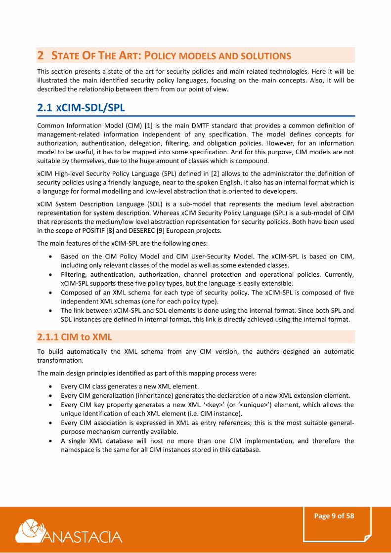
The refinement consists in a translation from the high-level specification to low-level rules specified by a language based CIM-Policy Information Model (i.e. xCIM-SPL or internal format). The tools for policy refinement and manipulation provide a Policy Console and a Policy Translation Service which permit the definition and refinement of high-level rules. These tools reduce the errors and permit additional checks. Regarding the translation process, Figure 2: Policy Refinement shows how the process is based on the direct transformation of the SPL elements to xCIM-SPL elements. Due to the lack of information provided by the natural human concepts, the authors use templates to fill the required information, generating finally the final xCIM-SPL result. The tasks Transform and Complete showed in the figure, are deployed by XML Style Sheets (XSL) transformation because all documents (i.e. templates, xCIM-SPL definitions and SPL definition) are represented by XML.
Page 11 of 58
Figure 2: Policy Refinement
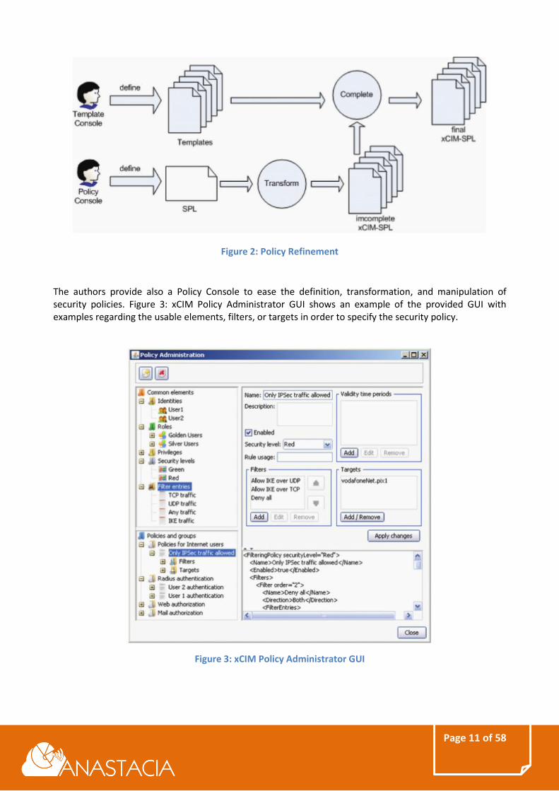
The authors provide also a Policy Console to ease the definition, transformation, and manipulation of security policies. Figure 3: xCIM Policy Administrator GUI shows an example of the provided GUI with examples regarding the usable elements, filters, or targets in order to specify the security policy.
Figure 3: xCIM Policy Administrator GUI
Page 12 of 58
2.2 SECURED - HSPL/MSPL
High-level Security Policy Language (HSPL) and the Medium-level Security Policy Language (MSPL) are two abstractions defined within the European project SECURED to specify the security policy.
2.2.1 HSPL
High-level Security Policy (HSPL) [3][4] is a policy language suitable for expressing the general protection requirements of typical non-technical end-users, such as “do not permit access to illegal content” or “block access to peer-to-peer networks”, generally following this form:
HSPL policies may be also presented as sets of constrained natural language sentences that could be directly selected by the users. The basic idea of this point will be to model the HSPL by using the Model-View-Controller (MVC) paradigm. By following this approach, the structure of a HSPL statement is the model, the set of sentences, expressed by using natural language, is the view (HSPL view) and the transformations (i.e. the representation from HSPL view to HSPL) are performed by the controller. In what follows, different kind of HSPL examples are given:
HSPL Example
Alice is not authorized to access Internet traffic
(type of content, {illegal websites})
HSPL Template Example
Bob enables basic parental control
HSPL View Example
Allow Internet traffic from 20:00 to 22:00 tz GMT+1 for Alice
Alice is authorized to access Internet traffic
(time period, {20:00-22:00 GMT+1})
2.2.2 MSPL
While HSPL is a high-level policy abstraction, the Medium-level Security Policy Language (MSPL) [3][4] is the policy abstraction used for expressing specific configurations in a device-independent format. That is, an abstract language with statements related to the typical actions performed by various security controls (e.g. matching patterns against packet headers, keeping track of connection status, identifying the MIME type of a payload), but expressed in a generic syntax. PSA (Personal Security Application) is the component within the SECURED project architecture which actually processes the network traffic. It is responsible to enforce a security policy as specified by the user.
Page 13 of 58
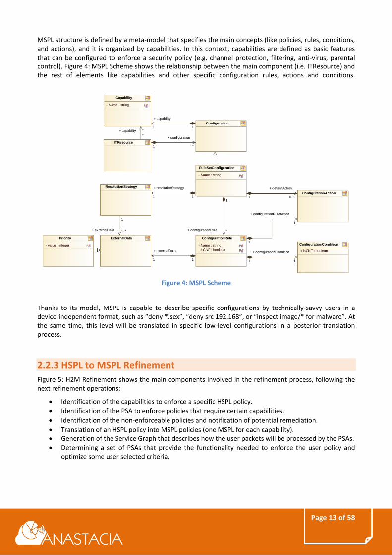
MSPL structure is defined by a meta-model that specifies the main concepts (like policies, rules, conditions, and actions), and it is organized by capabilities. In this context, capabilities are defined as basic features that can be configured to enforce a security policy (e.g. channel protection, filtering, anti-virus, parental control). Figure 4: MSPL Scheme shows the relationship between the main component (i.e. ITResource) and the rest of elements like capabilities and other specific configuration rules, actions and conditions.
Figure 4: MSPL Scheme
Thanks to its model, MSPL is capable to describe specific configurations by technically-savvy users in a device-independent format, such as “deny *.sex”, “deny src 192.168”, or “inspect image/* for malware”. At the same time, this level will be translated in specific low-level configurations in a posterior translation process.
2.2.3 HSPL to MSPL Refinement
Figure 5: H2M Refinement shows the main components involved in the refinement process, following the next refinement operations:
Identification of the capabilities to enforce a specific HSPL policy.
Identification of the PSA to enforce policies that require certain capabilities.
Identification of the non-enforceable policies and notification of potential remediation.
Translation of an HSPL policy into MSPL policies (one MSPL for each capability).
Generation of the Service Graph that describes how the user packets will be processed by the PSAs.
Determining a set of PSAs that provide the functionality needed to enforce the user policy and optimize some user selected criteria.
Page 14 of 58
Figure 5: H2M Refinement
2.2.4 MSPL to low-level configuration refinement
Since MSPL is still device-independent, it must be translated into a specific security configuration for a specific PSA. Figure 6: M2L Refinement shows the main interconnections in order to achieve that goal, invoking the M2L module for each PSA. To support a wide set of low-level security controls, the translation must be designed to be multi-device (e.g. netfilter/iptables or PF for a stateful firewall). The proposed approach develops the M2L translation module (with related API) which takes as input MSPL statements, identifies the set of security controls of the PSA and invokes the related M2L plugin(s) to generate the specific configuration. Each M2L plugin must contain the logic to perform the translation for a specific security control implementation.
Page 15 of 58
Figure 6: M2L Refinement
2.3 INFORMATION MODEL OF NETWORK SECURITY FUNCTIONS
CAPABILITIES
Based on flexibility, high level of abstraction, automation, and scalability, a set of abstract and vendor-neutral capabilities with standard interfaces is needed together with a model of capabilities that allows to unambiguously determine what Network Security Functions (NSFs) can do in terms of security policy enforcement.
Furthermore, when an unknown threat (e.g., zero-day exploits, unknown malware, and APTs) is reported by a network security device, new capabilities may be created, and/or existing capabilities may be updated. These new capabilities may be sent to and stored in a centralized repository, or stored separately in a local repository. In either cases, a standard interface is needed during this automated update process.
There are two types of Interfaces to Network Security Functions (I2NSF) [5]:
Interface between I2NSF clients and a security controller.
Interface between NSFs.
Page 16 of 58
Figure 7: I2NSF Interfaces
In defining the capabilities of an NSF, the “Event-Condition-Action” (ECA) policy rule set model is used, and it consist of:
An Event is defined as the occurrence of an important change in the system being managed, and/or in the environment of the system being managed.
A Condition is a set of attributes, features, and/or values that are to be compared with a set of known attributes, features, and/or values in order to make a decision.
NSFs provide security functions by executing various Actions.
2.3.1 Information Model
An information model will be developed in order to describe in an abstract and vendor-independent manner all the aspects related to the capabilities of NSFs. The I2NSF capability interface is in charge of controlling and managing the NSFs by means of the information about the capabilities each NSF owns. This is done using the following approach:
The user of the capability interface selects the set of capabilities required to meet the needs of the application.
A management entity uses the information model to match chosen capabilities to NSFs, independent of vendor.
A management entity takes the above information and creates or uses vendor-specific data models to install the NSFs identified by the chosen capabilities.
Control and monitoring can then begin.
The capability interface is used for advertising, creating, selecting, and managing a set of specific security capabilities independently from the type and vendor of device that contains the NSF.
Page 17 of 58
Figure 8: Info model
This model assumes that another, generic, information model for defining ECA policy rules (which includes a specific one for the CA part of ECA policy rules) exists outside of I2NSF, and these Capabilities are modelled as metadata.
The external ECA Information Model supplies at least a set of objects that represent a generic ECA Policy Rule, and a set of objects that represent Events, Conditions, and Actions that can be aggregated by the generic ECA Policy Rule. It is assumed that the external ECA Information Model has the ability to aggregate metadata. Capabilities are then sub-classed from an appropriate class in the external Metadata Information Model; this enables the ECA objects to use the existing aggregation between them and Metadata to add Metadata to the appropriate ECA objects.
2.3.2 Capabilities for security policy enforcement
Security Capabilities are intended to describe the potentiality that Network Security Functions (NSFs) have for security policy enforcement purposes. Therefore, Security Capabilities are represented as abstract functionalities that an NSF owns in terms of enforcement actions, conditions that determine the packet(s) or traffic on which the actions should be enforced, and other mechanisms that the NSF uses to determine the actions to enforce. That is, the Security Capabilities model defines without any ambiguity the things a function can do in term of security policy enforcement.
The Capability Model has been designed to support at least capability matching, i.e., to identify the NSFs in a catalogue that can perform the operations required to enforce a high-level policy.
2.3.2.1 The CA Policy Model
The goal is to build a model of security capabilities that allow automatic management of virtualized systems, where intelligent components can properly identify and manage NSFs, and allow NSFs to properly declare their functionality so that they can be used in the correct way.
2.3.2.2 Geometric model of CA Policies
Policies are specified by means of a set of rules in the “if condition then action'' format. Rules reformed by a condition clause and an action clause. All the actions available to the security function are well known and organized in an action set A.
For filtering controls, the enforceable actions are Allow and Deny, thus A={Allow,Deny}. For channel protection controls, they may be informally written as “enforce confidentiality'', “enforce data authentication and integrity'', and “enforce confidentiality and data authentication and integrity''. However, these actions need to be instantiated to the technology used, for instance AH-transport mode and ESP-transport mode (and combinations thereof) are a more precise and univocal definition of channel
Page 18 of 58
protection actions. In this scope, the conditions are typed predicates concerning a given selector. A selector describes the values that a protocol field may take, e.g. the IP source selector refers to the IP source field in the IP header. A condition on a given selector matches a packet if the value of the field referred to by the selector belongs to the condition. To consider conditions in different selectors, the decision space is extended using the Cartesian product because distinct selectors refer to different fields, possibly from different protocol headers.
Unfortunately, not all its subsets are valid condition clauses: only hyper-rectangles or union of hyper-rectangles (as they are Cartesian product of conditions) are valid. This is an intrinsic constraint of the policy languages as they specify rules by defining a condition for each selector. Languages that allow specification of conditions as relations over more fields are modelled by the geometric model, as more complex geometric shapes determined by the equations.
Geometric model example
The conditions are s1 <= S1 (read as s1 subset of or equal to S1) and s2 <= S2 (s1 of or equal to S2), both s1 and s2 match the packet x1, while only s2 matches x2.
Figure 9: Geometric model
Page 19 of 58
2.3.2.3 Condition Types
The authors categorize the types of selectors in exact-match, range-based, regex-based, and custom-match.
Exact-match example
proto = tcp, udp (protocol type field equals to TCP or UDP)
proto != tcp (protocol type field different from TCP)
2.3.2.4 Model of Capabilities for Policy Specification and Enforcement Purposes
Capabilities can be used for two purposes: describing generic security functions, and describing specific products. With the term generic network security function (GNSF), we denote known classes of security functions. The idea is to have generic components whose behaviour is as well understood as for the network components (i.e., a switch is a switch and we know to use it even if it may have some vendor-specific functions). These generic functions can be substituted by any product that owns the required capability at instantiation time.
Authors found the common features and defined a set of generic NSFs, including packet filter, URL filter, HTTP filter, VPN gateway, anti-virus, anti-malware, content filter, monitoring, and anonymity proxy that will be described in a data model TBD.
Capabilities are defined by a 4-tuple (Ac; Cc; RSc; Dc):
(Ac; Cc; RSc; Dc) <= (XAC; XCC; XRSC; XDC)= K
where XAC is the set of all the supported actions, Ac <= XAC is a set of actions that determine the actions actually available at the NSF N, XCC is set of all the supported conditions types, Cc <= XCC is the set of conditions actually available at the NSF N, XRSC is the set of all the supported resolutions strategies, RSc <= XRSC is the set of resolution strategies that can be used to solve conflicts of multiple matching rules at the NSF N, XDC={F} U XAC, is the set of all the existing actions plus a dummy symbol F, a placeholder value that can be used to indicate that the default action can be freely selected by the policy editor and Dc <= XDC.
Dc may be {F}, to indicate that the default action can be freely selected by the policy editor, thus it can vary in every policy It can also be an explicit action {a<=XAC} to indicate that the default action is fixed and the policy editor will not have the possibility to choose it.
2.3.2.5 Information Sub-Model for Network Security
The purpose of the Network Security Information Sub-Model is to define how network traffic is defined and determine if one or more network security features need to be applied to the traffic or not.
Figure 10: Information Sub-Model 1
Figure 10: Information Sub-Model 1, illustrates the ECAPolicyRule, along with the Event, Condition, and Action Objects. The Network Security Sub-Model defines security-specific ECA policy rules, as well as Events, Conditions, and Actions.
Figure 11: Information Sub-Model 2
Page 21 of 58
I2NSF Policy Rule example (in pseudo code)
IF <event-clause> is TRUE
IF <condition-clause> is TRUE
THEN execute <action-clause>
END-IF
END-IF
2.4 POLICY MODELS RELATIONSHIP
Figure 12: Policy Models Relationship shows the relationship between the illustrated proposals. As can be shown, from our point of view, HSPL/MSPL extends and improve the idea exposed on xCIM-SPL/SDL of two level of device-independent languages and a lower dependent one. On the other hand, I2NSF IETF group reuses and extends the capability concept on the I2SNF Framework.
Figure 12: Policy Models Relationship
Framework for Interface to Network Security is described on draft draft-ietf-i2nsf-framework-04 [5] and defines a reference model for I2NSF. A model of a Security Capabilities is presented on draft-baspez-i2nsf-capabilities-00 [6], and draft-xia-i2nsf-capability-interface-im-06 [11]is focused on the capability interface of NSFs proposing an information model for network security functions management. The last two drafts are merged on draft-xibassnez-i2nsf-capability-00 [7].
Page 22 of 58
3 ANASTACIA ARCHITECTURE OVERVIEW The ANASTACIA system model is structured as a set of layers that provide a broad view of the framework and stand out its integration within IoT infrastructures. ANASTACIA is envisioned as a framework integrated on top of an IoT infrastructure where IoT devices, physical and virtual network elements interact in the Data Plane. On top of that, the Control Plane manages the computing, storage, and networking resources in the Data Plane by leveraging SDN controllers, NFV orchestration platforms, and IoT controllers.
Errore. L'origine riferimento non è stata trovata. represents the high-level view of the ANASTACIA ramework, which extends the ANASTACIA system model by expanding the functions of the ANASTACIA core. The Autonomic Plane includes the components that provide the ANASTACIA framework with its intelligence and dynamic behaviour. This plane can be divided into three sub-planes, which carry out specific activities within the framework:
The Security Orchestrator Plane organizes the resources that support the Enforcement Plane, carrying out activities such as the transformation of security properties to configuration rules and aligning the security policies defined by the security interpreter with the provisioning of relevant security mechanisms. It has the whole vision of the underlying infrastructure and the resources and interfaces available at the Security Enforcement Plane.
The Security Enforcement Plane connects the ANASTACIA core with the IoT Platform (Data and Control planes), managing the interactions among objects and components for the enforcement of the security policy defined at the User Plane. This plane supports the enforcement of configurations and reactions triggered by the Security Orchestrator Plane, in order to preserve the expected security level. At this plane, the agents that support the monitoring of IoT devices or the enforcement of reactions are instantiated, either if they are operating on remote or directly attached to the device.
The Monitoring and Reaction Plane connects to the IoT Platform through the Security Enforcement Plane in order to collect security-focused information related to the system behaviour. At this plane, intelligent data-driven automated and contextual monitoring of activities at embedded devices, legacy systems and IoT devices by retrieving signals, event logs, traces, heartbeats signals, status reports or operational information. This plane also evaluates the fulfilment of the security policy by checking security models or threats signatures, detecting anomalies and creating reactions to mitigate such anomalies, in terms or reconfigurations and alerts to system administrators.
Additionally, on top of the architecture, the User Plane and the Seal Management Plane interact with the Autonomic plane:
The User Plane includes interfaces, applications and tools that help system administrators to manage the IoT platform through the ANASTACIA framework. For example, at this plane system admins are able to edit the security policies that govern the underlying IoT platform.
The Seal Management Plane is in charge of providing users with a real-time indicator of the overall security level.
Page 23 of 58
Figure 13: High level ANASTACIA framework
The next step of the methodology comprises the definition of the detailed architecture. The high level architecture can be used to identify the main activities to be carried out by the ANASTACIA framework, which is used to identify the specific components that are part of every identified plane. By analysing the use cases reported in D1.2 we can identify five main activities to be supported by the platform:
Security policy set-up activity. This is the initial process triggered once a security policy has been defined by the user. In this process the policy has to be configured in the platform in order to be enforced. The interpretation of the security policy claims, the configurations required to monitor the security controls associated to a policy or the definition of thresholds to identify policy violations, are some activities carried out by this process.
Security policy orchestration activity. Once the policy has been defined, it is necessary to enforce the controls specified within the policy. To orchestrate the selected IoT/SDN/NFV-based security enablers, appropriate interactions with the relevant management modules are required.
Security monitoring activity. In this process the monitoring information is extracted from the devices through monitoring agents and according to the security controls interpreted from the security policy. In this activity, the monitoring data is filtered and aggregated in order to carry out its analysis and the detection of anomalies.
Security reaction activity. In this process the detected anomalies are evaluated to design counter measures in order to mitigate the effects of attacks and potential threats.
Dynamic security and privacy seal creation activity. In this process, relevant information about detected threats, monitored information is evaluated to create a seal that determine the level of security guaranteed/offered by an IoT platform.
Section 4 describes every process in detail, including components involved, conditions and sequence details. We can match activities to these planes and identify sub activities that determine the components.
Page 24 of 58
The Security policy set-up activity requires the following components:
An Editor at the User plane that can be used by the User/System admin to set the Security policy to be enforced in the IoT platform.
An Interpreter in the Security Orchestration Plane that will transform the Security policy (closer to a human readable policy) to a machine readable policy that is able to represent lower configurations parameters.
A Security Enabler Provider in the Security Orchestration Plane, that is able to identify the security enablers which can provide specific security capabilities, so to meet the security policies requirements.
A Security orchestrator in the Security Orchestration Plane is responsible for selecting the security enablers to be used in the policy refinement process and configuring the Monitoring and Reaction Plane according to the security policy to enforce.
The Security policy orchestration activity requires the following components:
A Security orchestrator that has the whole vision of the subjacent infrastructure and is able to trigger the enforcement of the defined policies using the corresponding configurations or tasks obtained during the policy refinement process.
The elements contained in the Security Enforcement Plane, including the IoT controllers, NVF orchestrators, SDN controllers and, in general, all the elements enabling the configuration of the resources offered by the IoT devices and the physical/virtual network elements in the underlying infrastructure, as shown in Errore. L'origine riferimento non è stata trovata..
The Security monitoring activity requires the following components:
A set of Monitoring Agents interfacing between the Monitoring and Reaction Plane and the Security Enforcement Plane. These agents are responsible for retrieving monitoring Data from the devices.
A Monitoring module in the Monitoring and Reaction Plane that filter and process monitoring data received from IoT devices. To this end, this module would require several subcomponents:
o A Data Filtering and pre-processing. This component will filter the raw monitoring data received from agents, carrying out an initial pre-processing of the received information in order to be correctly analysed. The filtering activity will be carried out based on the initial configuration received from the Security Orchestrator during the Security policy set-up.
o A Data Analysis that will analyse the filtered monitoring data to detect potential threats or ongoing attacks. This component is supported by a set of Attack signatures that keep track of the latest attacks and their signatures in order to identify them.
The Security reaction activity requires the following components:
A Reaction module in the Monitoring and Reaction Plane that receive the detected threats and attacks and create the countermeasures that react to them. This module would require several subcomponents:
o A Security Model Analysis, which is configured during the Security Policy Set-up with the Security Models available at the IoT platform. The security models determine the set of possible actions that can be carried out at the IoT platform, and will determine the reactions that can be deployed in the IoT platform. These security models are related to the configurations created by the Policy Interpreter, as will be described Section Errore. L'origine riferimento non è stata trovata..
o A Verdict and Decision Support System that, according to the available Security Model and according to a set of pre-configured reactions, is able to determine the most suitable countermeasure to mitigate the detected attack/threat.
o A Mitigation Action Service that transforms the proposed countermeasures to a format that is suitable to be implemented by the Security Orchestrator.
Page 25 of 58
o A Security Alert Service that notifies the User/System Admin about the alerts, events or countermeasures found for a specific threat/attack. This model is compatible with the User/System admin supporting the reaction module, for example, to choose one specific countermeasure or to give permissions to apply it.
The Dynamic security and privacy seal creation activity takes place at the Seal Manager and requires information from the Monitoring and Reaction Plane. The Seal Manager includes the following components:
A Dynamic Security and Privacy Seal, in charge of analysing the system and creating the seal that determines the current security level offered by the platform.
A Dynamic Security and Privacy Seal User Interface that is used by the User/System admin to visualize the current status of the IoT platform.
Mapping these identified components to the planes of the high level architecture results in the detailed ANASTACIA architecture represented in Figure 14. The diagram shows also the relationship between components.
Figure 14: ANASTACIA architecture
The following sections will describe in detail the processes implemented by the ANASTACIA framework related with the security policies.
Page 26 of 58
4 SECURITY POLICY MODELS It is envisaged that ANASTACIA framework will reuse and extends the security policy models from the European SECURED project, relaying also on capability concept. It will inherit, extend and adapt HSPL, MSPL and capabilities in order to comply with the ANASTACIA framework objectives.
The High-level Security Policy Language (HSPL) and the Medium-level Security Policy Language (MSPL) are two policy languages defined within the European SECURED project to specify security policies. HSPL is the policy language suitable for expressing the general protection requirements of typical non-technical end-users, such as “do not permit access to illegal content” or “block access to peer-to-peer networks”. MSPL is an abstract language with statements related to the typical actions performed by various security controls but expressed independent of the final devices, it means, expresses specific configurations by technically-savvy users in a device-independent format, such as “deny *.sex”, “deny src 192.168”, or “inspect image/* for malware”.
Both policy languages are based on XML and are focused on the capability concept. A capability denotes any kind of security functionality that can be provided by a Personal Security Application (PSA). A PSA implements some security controls, generally, by a software module, e.g. filtering, logging or authentication. Specifically, the model includes capabilities like authorization, authentication, data protection and general security.
4.1 HIGH-LEVEL SECURITY POLICY LANGUAGE (HSPL)
The High-level security policy language (HSPL) is a security policy language with a high level of abstraction which allows to model security policies in an independent way of the subjacent technology, being this a key feature for the framework, allowing multiple implementations and possible enforcement points for a same high-level policy. This point of abstraction also provides other important features such as allowing a non-technical end-user to specify general protection requirements without a deep knowledge of the lower layers of the system.
Since the main idea of the HSPL is to define high level policies capable to model security requirements which indicates who is allowed or not to apply some action over some element under some conditions, the HSPL structure was defined in SECURED project as:
Where the sbj indicates the subject, who aims to perform some action over the element, act represents
the action to be carried out by the subject, the obj indicates the element or resource where will be apply the action and finally, a set of fields and values which indicates some conditions about the action in the security requirement.
4.1.1 Subject
Considering the nature of the present project, the following subjects capable of requesting security requirements have been considered:
Specific user, e.g. Alice.
User group, e.g. Administrators.
Specific device/VNF, e.g. Sensor-A.
Device/VNF group, e.g. 1st floor sensors.
Page 27 of 58
4.1.2 Action
For the scope of ANASTACIA, a subset of actions provided by the SECURED HSPL has been considered, which will allow the modelling of security policies capable of enforcing the main security requirements identified in the use cases:
Authorized/No Authorized to access: Indicates if the subject will be able to access or not to some element or resource.
Enable: Action which activates some element or resource.
Reduce: apply bandwidth limitation.
Protect confidentiality: To guarantee communication´s confidentiality.
Protect integrity: To guarantee communication´s integrity.
Protect confidentiality integrity: To guarantee communication´s confidentiality and integrity.
4.1.3 Object
As for the element or resource where the action will be performed, a subset of the SECURED HSPL objects has been selected. The objects correspond to the main use cases of the ANASTACIA project are:
Internet traffic: The traffic beyond the own network
DNS traffic: Traffic related with domain name resolution system.
Intranet traffic: The traffic of the own network.
All traffic: Whatever traffic
Resource: The element/object where the action is performed.
IDS, IPS: Intrusion detection system and intrusion prevention system.
Bandwidth: The rate of data transfer, measured in bits per second.
DDos attack protection: Protection against distributed denegation of service attack.
4.1.4 Field condition
The field conditions establish the constraints about the action to perform. HSPL defines several kinds of conditions as:
Time: To specify timing conditions, e.g. the security requirement duration.
Specific URL: Concrete URL or website.
Type of content: Specific content affected by the policy, e.g. social networks.
Traffic target: Specific traffic affected by the policy e.g. Sensor´s A traffic.
Bandwidth value: The bandwidth rate.
Resource value: The specific resource.
4.1.5 Combining HSPL components
This section exposes how the HSPL components, which are, subject, action, object and condition fields can be combined to build a complete HSPL policy. Table 1: HSPL Action - Object combination
shows the combination among the actions and the possible objects for the HSPL applied on the ANASTACIA framework.
Page 28 of 58
Action/Object
Inte
rnet
tra
ffic
DN
S tr
affi
c
Intr
anet
tra
ffic
All
traf
fic
Re
sou
rce
IDS,
IPS
Ban
dw
idth
DD
os
atta
ck p
rote
ctio
n
Authorized/No Authorized to access
Enable
Reduce
Protect confidentiality
Protect integrity
Protect confidentiality integrity
Table 1: HSPL Action - Object combination
Table 2: HSPL Field - Object combination shows the possible combinations of the conditional fields and objects for the HSPL components in ANASTACIA framework.
Field/Object
Inte
rnet
tra
ffic
DN
S tr
affi
c
Intr
ane
t tr
affi
c
All
traf
fic
Re
sou
rce
IDS,
IPS
Ban
dw
idth
DD
os
atta
ck p
rote
ctio
n
Time
Specific URL
Type of content
Traffic Target
Bandwidth value
Resource value
Table 2: HSPL Field - Object combination
Page 29 of 58
4.1.6 HSPL example
According to the exposed combinations of the components for the HSPL in previous sections, here is shown a simple example (the real one is modelled on XML) corresponding to the sentence “Alice will does not have Internet access from 20:00 to 22:00”:
Alice is not authorized to access Internet traffic (time period, {08:00-18:00 GMT+1})
The previous sentence is modelled in XML as the following, specifying the subject and the identification of the HSPL as attributes of the XML element.
Figure 15: HSPL example, indicates that Alice, as a subject, is authorized to access, as an action, Internet traffic, as an object, during a certain period of time as a condition field. As can be shown, this level only expresses a security requirement without any technical or deeper specific implementation information.
4.2 MEDIUM-LEVEL SECURITY POLICY LANGUAGE (MSPL)
The Medium-level security policy language (MSPL) is a security policy language with a medium level of abstraction. It is still independent on the subjacent technology, but closer to it than an HSPL one. This exposes in a general way a set of actions suitable by the most common applicable security controls e.g. ALLOW or DENY IP_ADDRESS sentences, which is also interesting for technical users.
Regarding the structure of MSPL, the main representative components which compound the medium level language could be ITResource, Capability and Configuration.
4.2.1 ITResource
Represents a piece of software or hardware capable to applying the enforcement of the security policy (thereinafter Security Enabler). Each ITResource implements some capabilities which allow it to enforce security configurations. For instance, a Security Enabler with filtering capabilities must be able to be configured indicating the source or destination of the affected traffic, but since MSPL offers a medium level of abstraction, the configuration will be not yet specific for a final device.
Page 30 of 58
4.2.2 Capabilities
The concept of capability exposes a kind of security functionality which must be provided by a piece of software or hardware (Security Enabler). For instance, if the ANASTACIA framework offers a Security Enabler capable of performing filtering actions, it must implement a filtering capability and must be ready to be configured with the most common filtering fields, e.g. source address, destination address and so on. Among the capabilities specified for the SECURED project, it has been selected and extended the following as the main relevant options to the ANASTACIA framework:
AUTHORISE_ACCESS_RESOURCE
AUTHENTICATION
ANONIMITY
FILTERING_L7
FILTERING_L4
TIMING
TRAFFIC_INSPECTION_L7
NETWORK_TRAFFIC_ANALYSIS
D_DOS_ATTACK_PROTECTION
PROTECTION_CONFIDENTIALITY
PROTECTION_INTEGRITY
DTLS_PROTOCOL
REDUCE_BANDWIDTH
IOT_CONTROL
4.2.3 Configuration
The configuration element denotes an abstract set of configuration settings, which are independent to the final Security Enablers. In specific, a configuration is composed by a set of configuration rules and a configuration action. On the other hand, a configuration rule can contain a configuration rule action and a configuration condition. Since different capabilities can require distinct kind of configuration, SECURED built a hierarchical approach. In the ANASTACIA framework will be contemplate as relevant the following:
PacketFilterCondition: able to represent fields related with filtering i.e. source address, source port…
TimeCondition: specifies relevant fields for timing e.g. Week day.
ApplicationLayerCondition: providing useful fields for the application layer like URL or the http method.
Figure 16: MSPL Scheme, shows the relationship among the main MSPL components. As can be observed, the ITResource represents the Security Enabler where will be possible to apply a configuration. This configuration will contain the capability or capabilities required by the policy and a set of rules compounding the policy enforcement configuration. The rule set will contain configuration rules and these will provide configuration rule actions and conditions. The configuration rule actions expose the action to perform e.g. FilteringAction, specifying the action type. On the other hand, the configuration conditions represent conditions for the actions e.g. The address which will be affected by the action.
Page 31 of 58
Figure 16: MSPL Scheme
Next section provides an example providing the XML code where can be observed in a practical way an instantiation of the main diagram elements.
4.2.5 MSPL Example
According to the exposed components for the MSPL, here is shown a simply example corresponding to the following HSPL sentence:
Alice is not authorized to access Internet traffic (time period, {08:00-18:00 GMT+1})
The process of how is obtained a MSPL policy will be explained along the document. At this point we only will focus on the MSPL definition for the specified example.
As can be observed in Figure 17: MSPL Example, the ITResource is representing a Security Enabler with capabilities of timing and filtering since is necessary to filter the Alice´s traffic in a specific range of time. The configuration then is focused on to allow by default the Alice´s traffic but stablish a configuration rule which deny the traffic in a specific time condition which is set in the concrete time range.
4.3 SECURITY POLICY MODELS DEFINITION
This section illustrates the policy models for High-level Security Policy Language and Medium-level Security Policy Language adapted and extended to the ANASTACIA framework.
4.3.1 HSPL
The HSPL model is compounded by several complex types. Following will be explained the most relevant model components. For deep information, the reader can consult the source, exposed in the 1.2 section.
The main complex type for the HSPL policy model is the hspl itself, which, as can be observed in Figure 18: HSPL Complex Type, is composed by an action, an object and fields complex type, including the subject as attribute of the type.
Action is a simple string type constrained to specific values for the SECURED scope. Figure 19: Action Simple Type, shows the most relevant actions applicable to the ANASTACIA framework according to the main identified policies.
Regarding the object type, it consists in a simple string type like the previous one, but this, Figure 20: Object Simple Type shows the string restriction for main values related with the ANASTACIA framework.
Finally, the fields type is a complex type composed in turn by a sequence of other complex types which provides to the field more accuracy specifying the policy.
Figure 21: Fields Complex Type illustrates the main components for the fields complex type. The time period is a complex type which allows to specify a time interval specifying days and time hours. The traffic target, specific URL, type content and resource values are complex types conformed by a sequence of simple string types. Finally, the values for the bandwidth limitation policies can be set through the downlink and uplink attributes of the main element.
4.3.2 MSPL
In the same way as HSPL, the Medium-level Security Policy language is also composed by different complex types, but this time, the main component is not an MSPL policy. Figure 22: ITResource element shows the main element for a MSPL policy. The ITResource represents a Security Enabler, so it is defined by a ITResourceConfiguration type.
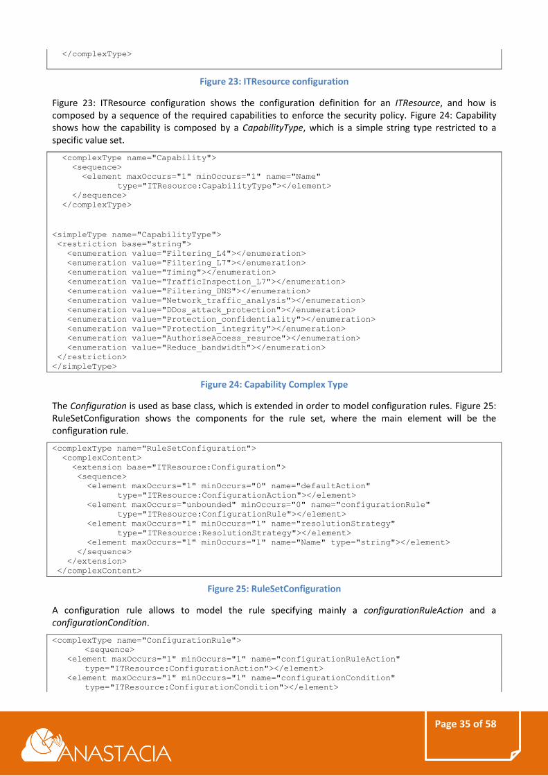
Figure 23: ITResource configuration shows the configuration definition for an ITResource, and how is composed by a sequence of the required capabilities to enforce the security policy. Figure 24: Capability shows how the capability is composed by a CapabilityType, which is a simple string type restricted to a specific value set.
The Configuration is used as base class, which is extended in order to model configuration rules. Figure 25: RuleSetConfiguration shows the components for the rule set, where the main element will be the configuration rule.
Extending the configurations, capabilities and configuration conditions exposed in Figure 23: ITResource configuration, Figure 24: Capability Complex Type and Figure 26: ConfigurationRule as base models, SECURED defines several configurations and capabilities which inherit to these models providing more accuracy to define different kind of policies. The following section exposes the security policy model definition regarding the main identified policies on ANASTACIA framework.
4.3.2.1 Access control Policy
Regarding the access control policy, have been modelled two different kind of policies, these are, authentication policies and authorization policies.
4.3.2.1.1 Authentication
In order to represent authentication policies, our model has extended the capability definition, the configuration rule actions as well as the action type.
Figure 27: Authentication illustrates how the model is extended in order to represent the new capability for authentication and a new specific action, which provides an enumeration to determine whether the
Page 37 of 58
authentication will be required or not. To determine the specific endpoint against the authentication, the model allows reusing filtering conditions, specifically the destination port and address. Besides, the application layer condition can be used to specify proper configurations at higher level such as the specific protocol, the URL or the method.
4.3.2.1.2 Authorization policy
In this case, the authorization policy is reusing an existing capability, but it extends the actions and the action types.
Figure 28: Authorization shows the selected capability for authorization purposes which corresponds with the AuthoriseAccess_resource capability. The configuration rule action has been extended, creating the AuthorizationAction which provides a AuthorizationActionType where it is possible to specify a restricted set of actions, capable to model if the subject will be able or not to access to the specified resource. To model the resource information, the configuration condition can be extended to a filtering configuration condition as well as it is happening for authentication policies, indicating all the information regarding the endpoint who requires authorization.
4.3.2.2 Filtering Policy
In order to model a Filtering policy, Figure 29:FilteringConfigurationCondition shows how the base configuration condition is extended, allowing to establish specific packet filter conditions, timing or application layer conditions.
The packet filter condition, as can be observed in Figure 30: PacketFilterCondition, enables the modelling of packet filtering related fields, as well as, the source address of the packet, the destination address, source and destination ports, the direction of the connection establishment, the interface and the protocol type.
The Application layer condition, showed in Figure 31: Application Layer Condition, exposes several fields related with the application layer, that is, fields related with the level four and upper in the OSI stack, as can be the URL, the specific HTTP method, the file extension as well as the mime type.
Regarding the capability, the base model is also extended like it is happening with the conditions. In this case, the extension provides fields in order to model the kind of filtering which will be performed by the security policy. Specifically, the filtering capability is extending the ChannelAuthorizationCapability which in turn extends the AuthorizationCapability which finally extends the base Capability model.
Using specific filtering configuration conditions and capability fields, the user is able to model filtering policies according to different purposes, protocols and so on. On the other hand, the filtering action delegates in a filtering action type which relies in a simple string type.
4.3.2.3 Channel Protection Policy
To model channel protection policies, the configuration condition is extended by DataProtectionCondition, which uses the packet filter condition to define the endpoints involved in the channel protection. In this case, the modelling related to the channel protection itself is reached through the extension of the configuration action base.
Figure 33: Data Protection Action shows the main components for a data protection action, these are, the technology involved described as string, the technology action parameters and a sequence of technology action security properties. The TechnologyActionSecurityProperty is extended for channel protection highlighting the Confidentiality complex type which extends it enabling to model fields like the encryption algorithm, the key size or the mode. The technology action parameter is showed in Figure 34: Action Parameters exposing the composition of this complex type, which provides several necessary fields for a security channel establishment, as can be, the key exchange among others.
The key exchange parameter allows to specify in a simply string data format a key exchange action, the hash algorithm to use, the symmetric encryption algorithm as well as the authentication type. The AdditionalNetworkConfigurationParameters can be extended depending on the specific purpose, to stablish
Page 40 of 58
concrete parameters for the network as the network address, the network mask, the DNS server and so on. On the other hand, the authentication parameters allow the user to model important information for the authentication process as the Pre-Shared Key value or path, the certificate for the Certification Authority or the public key information, this is, all necessary data to carry on an authentication process using certificates or shared keys.
Regarding the TechnologySpecificParameter, it specifies the technology will be used for the channel protection, this is, the base class is extended like in the previous cases in order to model the specific technologies using for instance the TLS_VPN_TechnologyParameter or TLS_SSL_TechnologyParameter.
Figure 35: TLS_VPN Technology Parameter shows the main relevant fields in order to apply a VPN policy, as can be the peer port to use, the level four protocol used through the VPN, as well as the virtual IP addresses. Since ANASTACIA framework is mostly IoT related, it is important to be able to model channel protection policies related with the IoT domain. To this aim, the model has been extended in order to allow the definition of Datagram Transport Layer Security (DTLS).
Figure 36: DTLS Technology Parameter shows the new capability defined as DTLS_protocol as well as the new technology parameter DTLSTechnologyParameter which is extending the most complete channel protection model, providing all the necessary fields in order to represent the security channel information.
Page 41 of 58
4.3.2.4 Anonymity Policy
Anonymity policies can be modelled through an extension of an operational policy (see Operational policies), starting from the EnableAction.
Inheriting from the EnableAction, the model allows to enable or disable an anonymity policy for the subject specified in the HSPL policy. At the same way in the previous cases, it is possible to extend the configuration condition, using a filtering configuration condition to be able to specify detailed information regarding the subject and the destination like the source address, port and application level information.
4.3.2.5 Operational policies
Beyond the basic security areas policies, the model provides a basic way to specify operational policies, these are those capable to specify operational actions like concrete deployments or configurations.
Figure 38: Operational Policy shows the EnableAction definition which extends the ConfigurationAction base, and is allowing to indicate an EnableActionType where it is possible to specify if the action is enabling or disabling the policy through a Boolean attribute and the resource where the action will be performed. Extending this main idea have been modelled IoT specific security operational policies like IoT control policies and Virtual IoT Honey Net policies.
Page 42 of 58
4.3.2.5.1 IoT control
To be able to model specific actions over the IoT domain devices, the policy model has been extended with a new capability and different IoT actions. This kind of actions will provide different options in order to interact with the IoT devices like could be, the power management, the IoT security management, or even firmware operations. Figure 39: IoT control capability shows the new enumerator value for the capability extension, this is, the IoT_control capability, as well as an example of configuration rule action extension, this is, the PowerMgmtAction which provides different action types like the ability of turn off or reset the IoT device.
<simpleType name="CapabilityType">
<restriction base="string">
<enumeration value="IoT_control"></enumeration>
</restriction>
</simpleType>
<complexType name="PowerMgmtAction">
<complexContent>
<extension base="ITResource:ConfigurationAction">
<sequence>
<element name="PowerMgmtActionType"
type="ITResource:PowerMgmtActionType" />
</sequence>
</extension>
</complexContent>
</complexType>
<simpleType name="PowerMgmtActionType">
<restriction base="string">
<enumeration value="OFF"></enumeration>
<enumeration value="RESET"></enumeration>
</restriction>
</simpleType>
Figure 39: IoT control capability
4.3.2.5.2 Virtual IoT Honey Net
The virtual IoT Honey Net will allow to specify a policy which will be able to model an IoT Virtual Honey Net deployment and configuration by replicating a real physical one. This model relies on the HoneyNet description language [10], that has been adapted and extended to cope with IoT scenarios. Figure 40: VIoT Honey Net shows an example of the model to represent the policy. In this case, the capability is still the IoT_control but the action is being extended as VIoTHoneyNetAction. That action intends to provide the specific action type VIoTHoneyNetActionType that will be performed and the physical IoT infrastructure ioTHoneyNet to replicate. Currently, these actions are DEPLOY, RESET or REMOVE.
Regarding the ioTHoneyNet, Figure 40: VIoT Honey Net shows how this kind of element responds to a specific type. This specific type has been conceived extending the base model defined by the authors of “Technology Independent Honeynet Description language” (see references). Figure 41: IoTHoneyNet Type illustrates the main composition of the complex type, where it is possible to specify not only a sequence of honey pots, even the description of the honey net, the net type and the routers and gateways if necessary.
Figure 42: ioT HoneyNet Type elements shows the definition for each element of the ioTHoneyNetType, excluding the ioTHoneyPot which will be illustrated later. In the figure, it is possible to see how the netType can be modelled using the network name/description and an identifier. To model the router, we can specify the name, a sequence of interfaces and routes, even the operating system. The interfaces in turn are composed by the name, mac address, ip address, an identifier, and the network to which it belongs. On the other hand, the route allows to define the next hop in order to reach a destination. Finally, we could define a gateway in similar way of the router specification.
In order to model the ioTHoneyPot, the honeyPotType was extended as can be seen in Figure 43:HoneyPot type. The base honey pot allows to specify similar values as in the router case, including the software specification of the honey pot (e.g. Apache) while in the IoT casesome relevant specific information has
Page 45 of 58
been added to the base scheme,, such as the model of the IoT device, its physical location, and the sequence of available resources.
The model of the IoT device will correspond with the name of the specific hardware model (e.g. “WISMOTE”). The physical location will allow to specify the (x,y,z) location in 3D coordinates and finally, the resources can be selected from a specific list of the most common IoT resources (e.g. TEMPERATURE, HUMIDITY...). Using this model scheme as a base, in the future, it will be possible to specify the main components of the physical IoT infrastructure.
Page 46 of 58
5 POLICY REFINEMENT AND ENFORCEMENT PROCESS Regarding the policy refinement workflow, it is envisaged the following behaviour; the Policy Interpreter will perform two separated refinement processes, offering two well differentiated APIs. Firstly, a refinement process from High-level Security Language (HSPL) to Medium-level security Policy Language (MSPL). This functionality will correspond to h2mservice API. Secondly, it will perform a translation from Medium-level Security Policy Language (MSPL) to lower level configurations. This functionality will correspond to m2lservice API.
5.1 HSPL MSPL REFINEMENT
Figure 44: HSPL Refinement shows the main workflow where the h2mservice API receives the HSPL policies, performing the refinement in order to generate the MSPL policies. Since the refinement process could require relevant information from the current system status as well as specific Security Enabler knowledge, the figure illustrates additional information inputs. As output of the process, it could generate the correspondent MSPL policies or even a report of non-enforceability if there are not possibilities to enforce the specified policy according to the system information and the security enabler provider information.
Figure 44: HSPL Refinement
The system information could provide relevant data about the status of the system such as:
1. Matching between identifiers and IP addresses. 2. Current deployed policies. 3. Current Infrastructure/architecture deployment information. 4. Current IoT Infrastructure/architecture deployment information. 5. Available resources to deploy.
On the other hand, the Security Enablers information could provide data regarding the available Security Enablers capable to enforce specific capabilities. Figure 45: HSPL Refinement Diagram shows the envisaged workflow for the HSPL to MSPL refinement which corresponds with the following action points:
1. The user will define the HSPL policy using a Policy Editor Tool. 2. The Policy Interpreter receives a refinement request, including the defined HSPL policy. 3. The Policy Interpreter identifies the main capabilities of the policy, for instance, if the HSPL is a
filtering policy, the Policy Interpreter will identify FILTERING as the main capability. 4. The Policy Interpreter will request from the Security Enabler Provider to provide the list of Security
Enablers capable to enforce the security policy using the identified capabilities.
Page 47 of 58
5. The Security Enabler Provider obtains the information regarding the Security Enablers from the Security Enabler repository.
6. The Security Enabler Provider will populate a Security Enabler list which will include the Security Enablers capable to provide the specified capabilities.
7. The Security Enabler Provider will provide the Security Enablers information to the Policy Interpreter.
8. The Policy Interpreter will perform a non-enforceability analysis of the HSPL policies against the Security Enablers provided.
9. If it is not possible to determine a viable policy enforcement, the Policy Interpreter generates a non-enforceable analysis report.
10. If the security policy can be enforced, the HSPL will be refined into MSPL policy or policies, taking into account each capability.
11. If there was any problem or system restriction during the refinement, the Policy Interpreter will provide a non-enforceability analysis report.
12. The refined policy will be uploaded to the Security Policy Repository. 13. The refined policy will be sent to the Security Orchestrator in order to start the deliberating
process.
Figure 45: HSPL Refinement Diagram
Regarding the h2mservice API, in order to facilitate the HSPL policy specified in the provided model, the input could consist of a JSON formatted file including the xml, e.g.:
Figure 46: h2mservice input example, shows how could be embedded the HSPL model onto the JSON file. Finally, when the refinement process has been finished successfully, the h2mservice API could to provide an output aligned with the received input, in format terms.
Page 48 of 58
{
“output”:{
“MSPL”: ["<?xml…<ITResource></ITResource>…],
}
}
Figure 47: h2mservice API output example
Figure 47: h2mservice API output example, shows how could be included the MSPL policy codified in xml onto the output JSON file.
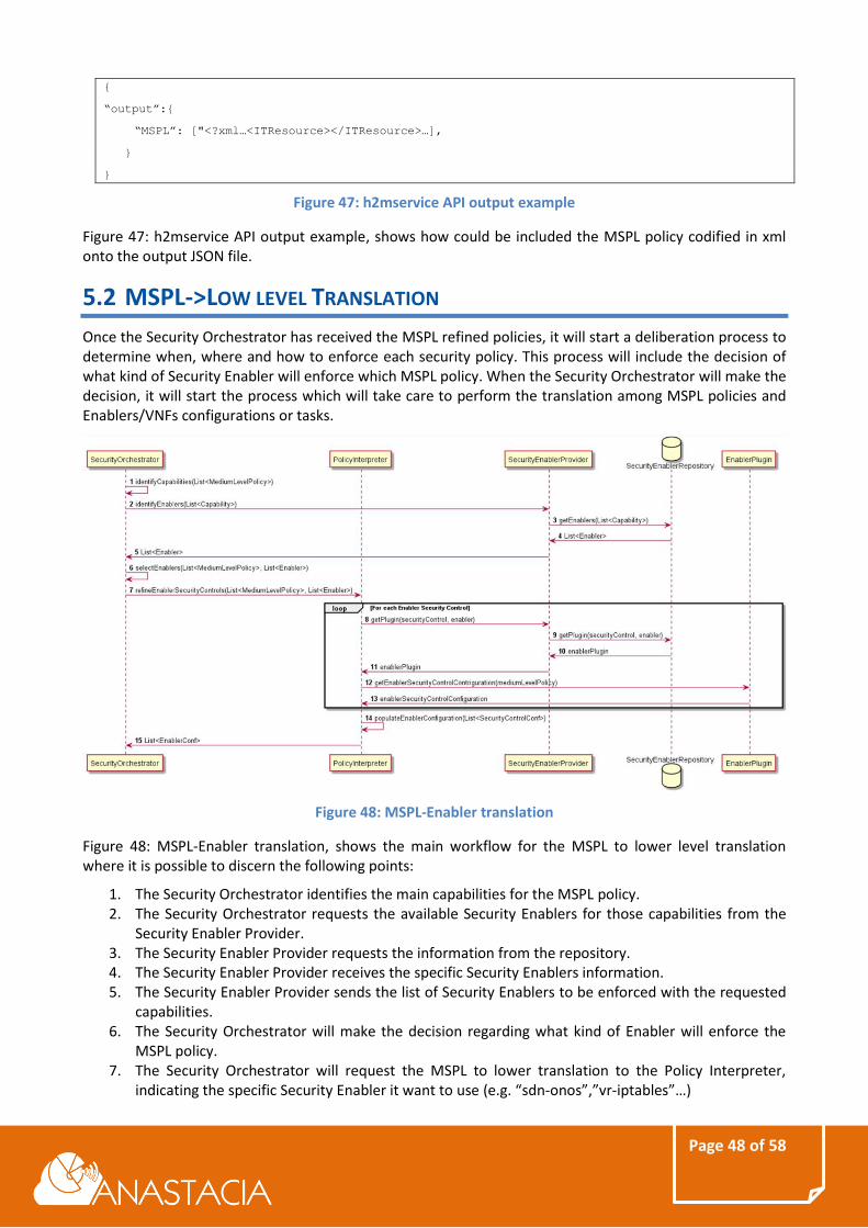
5.2 MSPL->LOW LEVEL TRANSLATION
Once the Security Orchestrator has received the MSPL refined policies, it will start a deliberation process to determine when, where and how to enforce each security policy. This process will include the decision of what kind of Security Enabler will enforce which MSPL policy. When the Security Orchestrator will make the decision, it will start the process which will take care to perform the translation among MSPL policies and Enablers/VNFs configurations or tasks.
Figure 48: MSPL-Enabler translation
Figure 48: MSPL-Enabler translation, shows the main workflow for the MSPL to lower level translation where it is possible to discern the following points:
1. The Security Orchestrator identifies the main capabilities for the MSPL policy. 2. The Security Orchestrator requests the available Security Enablers for those capabilities from the
Security Enabler Provider. 3. The Security Enabler Provider requests the information from the repository. 4. The Security Enabler Provider receives the specific Security Enablers information. 5. The Security Enabler Provider sends the list of Security Enablers to be enforced with the requested
capabilities. 6. The Security Orchestrator will make the decision regarding what kind of Enabler will enforce the
MSPL policy. 7. The Security Orchestrator will request the MSPL to lower translation to the Policy Interpreter,
indicating the specific Security Enabler it want to use (e.g. “sdn-onos”,”vr-iptables”…)
Page 49 of 58
8. The Policy Interpreter will receive the request and solicits a proper plugin in order to perform the translation to the Security Enabler Provider.
9. The Security Enabler Provider requests the plugin to the repository. 10. The Security Enabler Provider obtains the specific plugin. 11. The Policy Interpreter receives the plugin software. 12. The Policy Interpreter executes the plugin software, indicating the MSPL policy to translate. 13. When the plugin translation process finishes, the Policy Interpreter obtains the final
configurations/tasks. 14. The Policy Interpreter prepares the configuration/tasks to be sent. 15. The Security Orchestrator receives the final configuration/tasks to be enforced.
Regarding the m2lservice API, in order to facilitate the MSPL policy specified in the provided model, the input could consist on a JSON formatted file including the xml and the specific plugin to use, e.g.:
At the same way, once the process has been finished, the output could follow the same scheme. Figure 50: m2lservice API output, shows an example of output for the m2lservice API, in specific, illustrating an example for iptables plugin.
The following section will provide more information regarding the Security Enabler Plugins.
5.2.1 Security Enabler Plugin
A Security Enabler Plugin, inheriting and extending the concept from the SECURED project, is a piece of software which will define well-known callable methods which will take in charge to perform the translation among the MSPL policy and the specific configuration or task. The main goal of this plugin approach is to provide a plugin repository where the developers can contribute with their own plugins and solutions. Actually, it is envisaged the same policy could be enforced using different plugins. For instance, the same filtering policy can be enforced through SDN using different plugins for each SDN controllers, or by using a virtual router and configuring IPTABLES as firewall.
Inside of ANASTACIA scope, it is envisaged to provide the following plugins, in order to be able to enforce the main identified security policies:
Page 50 of 58
1. SDN ONOS Plugin: It will take in charge the MSPL policy translation onto a set of rules understandable by the ONOS controller.
2. SDN ODL Plugin: It will take in charge the MSPL policy translation onto a set of rules understandable by the OpenDayLight controller.
3. IPTABLES Plugin: It will be able to translate the MSPL policy onto iptables rules. 4. OpenWRT Plugin: It will be in charge to generate OpenWRT router configuration from an MSPL
policy. 5. Quagga Plugin: It will be in charge to generate Quagga router configuration from an MSPL policy. 6. Open Virtual Switch Plugin: It will generate OVS rules according to the specified policy. 7. PfSense Plugin: It will take in charge to generate the PfSense firewall configuration. 8. SNORT Plugin: It will translate the MSPL policy onto a SNORT monitoring rules. 9. DTLS/TLS Proxy Plugin: It will obtain the proxy configuration for DTLS/TLS secure connections. 10. VPN Plugin: It will generate the OpenVPN configuration from the secure policies parameters. 11. Kippo Plugin: It will perform the translation from MSPL to Kippo honeypot. 12. Cooja Plugin: It will translate the physical IoT system model provided to a Cooja virtual one. 13. vAAA XACML Plugin: It will generate the required configuration for the AAA infrastructure from the
MSPL policy. 14. Data Aggregator Proxy Plugin: It will translate the security policy to a configuration of a data
aggregator proxy in order to provide pseudonimity. 15. IoT Control Plugin: This plugin will be in charge of translating the operational IoT security policies
to the specific IoT Controller rules.
Page 51 of 58
6 USE CASE: SECURITY POLICY ENFORCEMENT IN IOT BUILDING
SCENARIOS
6.1 ISOLATING A COMPROMISED SENSOR
SensorA has reported to send the last 3-months average temperature values around 21 °C. A man-in-the-middle attacker (either by wire or wirelessly), introduces tampered temperature values which reports 10 °C periodically to the IoT Service Application. This attack type in BMS targets produces long term financial impact, due to the imagery loss in reaching the set-point. The attack is detected properly and identified, therefore now a policy must be applied to isolate SensorA from the rest of the BMS systems for a time period until further investigation takes place.
Figure 51: IoT Device Isolation
IoT Service Application (Context broker) will receive abnormal values from SensorA. Therefore, Reaction Module will be notified by Monitoring module. The Reaction Module will generate a reaction and will notify the orchestrator and the administrator, which could make the decision to apply different policies or directly act over the infrastructure to solve the incident. In this case we will suppose the Administrator has decided to apply the following security policies:
“SensorA is not authorized to access all traffic”
“SensorA must be disabled”
Figure 52: Policies to apply in natural language
Page 52 of 58
Figure 52: Policies to apply in natural language, shows the selected policies in natural language. These natural policy specification notations, can be represented in two different policies defined in HSPL, as defined as follows:
<hspl_list>
<hspl id="SensorA-1" subject="SensorA">
<action>no_authorise_access</action>
<objectH>AllTraffic</objectH>
<capabilities>
<capability_list>Filtering_L3</capability_list>
</capabilities>
</hspl>
<hspl id="SensorA-2" subject="SensorA">
<action>enable</action>
<objectH>resource</objectH>
<fields>
<tns:resource_values>
<tns:name_resources>PowerOff</tns:name_resources>
</tns:resource_values>
</fields>
<capabilities>
<capability_list>IoT_Control</capability_list>
</capabilities>
</hspl>
</hspl_list>
Figure 53: Use case HSPL example
As can be seen in Figure 53: Use case HSPL example, we are specifying two different high-level policies one for each sentence, having both as subject the “SensorA”. The first one specifies “no_authorize_access” as action for the object “AllTraffic” using as capability the “FilteringL3”. This means that the subject will cannot access to the network and will be used network filtering to achieve it. The second one specifies the subject must activate the “PowerOff” resource using the “IoT_Control” capability. It means that the device must power off itself through an IoT control message.
Once the HSPL policies are defined, the Policy Interpreter will receive them and will proceed with the refinement process, starting by identifying the capabilities. This case will correspond to filtering capability and IoT control capability. The Policy Interpreter then retrieves a list of enablers capable to enforcing them (i.e. SDN Enabler, IoT Controller Enabler) and will realize an early non-enforceable analysis report. If the policies are enforceable, could be generated the following MSPL policies for the specified capabilities:
Figure 54: Use case MSPL filtering example shows the instantiation example of the filtering MSPL policy, whereby a “FilteeringCapability” indicates as action “DENY” for all traffic whose source address corresponds with the “SensorA” ip address. Complementing this security policy, it was defined the second one, which in MSPL could look like following:
Figure 55: Use case MSPL IoT control example, Illustrates how the “PowerMgmtAction” is being instantiated, and how it was set to the value “OFF. Also, it is possible to see how the filtering model is being reused to specify the IoT device source address over which the action will be performed.
Page 54 of 58
6.2 RE-BOOTSTRAPPING
Related to the previous use case, when an attacker performs a man-in-the-middle attack between the IoT device and the IoT Application Service, the administrator decides to improve the security between them using a secure channel like Datagram Transport Layer Security (DTLS), in order to protect the communication. DTLS is a security protocol based on Transport Layer Security (TLS) that provides secure communications using as subjacent layer datagram protocols.
Figure 56: DTLS Enforcement
In this case, we will suppose the administrator has selected the following high-level policies in order to represent a secure bidirectional communication between the IoT device and the IoT Application Service:
“SensorA protects all traffic (traffic target, {IoTAppService})”
“IoTAppService protects all traffic (traffic target, {SensorA})”
Figure 57: Channel protection policies close to natural language
These notations could be expressed as two different HSPL policies, actually, Figure 58:HSPL channel protection example, shows an example of channel protection high-level security policy, where can be observed how the first policy has been modelled, indicating that, the subject “SensorA” must take the action “prot_conf” (protects confidentiality) over “AllTraffic” for the target “IoTAppService” using the capability “DTLS_protocol”. This is, the IoT device “SensorA” must use DTLS protocol when it wants to communicate with the IoT Application Service. On the other hand, the second policy will be modelled at the same way, just inverting the subject and the traffic target elements.
<hspl_list>
<hspl id="SensorA-1" subject="SensorA">
<action>prot_conf</action>
<objectH>AllTraffic</objectH>
<fields>
<traffic_target>
<target_name>"IoTAppService"</target_name>
</traffic_target>
</fields>
<capabilities>
Page 55 of 58
<capability_list>DTLS_protocol</capability_list>
</capabilities>
</hspl>
</hspl_list>
Figure 58:HSPL channel protection example
Once the HSPL policies are defined, the Policy Interpreter will start the policy refinement process, providing as a result an MSPL policy like the following one:
Figure 59: MSPL DTLS channel protection example, illustrates an instantiation of MSPL channel protection security policy using DTLS protocol. In this case the configuration contains as capability
Page 56 of 58
“EncryptionCapability”, and the instantiation is specifying the use of DTLS as “DTLS_TechnologyParameter” from the local endpoint “SensorA” to the remote end-point “IoTAppService”. The specific technology security properties also have been modelled, indicating “AES” as an encryption algorithm with a key size of “128” bits and “CCM” mode. As integrity algorithm “sha1” has been selected and the authentication will be based on “pre-shared key”.
Page 57 of 58
7 CONCLUSIONS This document has detailed the main security policy models to define the policies envisaged in the ANASTACIA framework. To accomplish this aim, this document has reviewed the current state of art regarding the techniques, technologies and policy languages, establishing a relationship between them. This study has served as baseline to grasp ideas and reuse extended modelling concepts such as the two-level security policies, the capabilities and the policy refinement. The present document exposes how to adapt and evolve these concepts in order to apply them over the ANASTACIA framework. Thus, the models and processes have been extended in order to cope with the main identified security policies for the main scenarios being addressed in ANASTACIA project.
The document has also provided real policy examples for an IoT building management system scenario. In this regard, it has been instantiated different security policies for distinct purposes such as IoT device isolation, which comprises operational and filtering policies, as well as channel protection use case, which involves a channel protection policy over several infrastructure elements.
It should be noticed that this deliverable has provided the foundations for the policy modelling. Nonetheless, this design might be extended, evolved as the project evolves. Possible modifications and extensions would be included in upcoming ANASTACIA deliverables, mainly in the scope of WP2.
Page 58 of 58
8 REFERENCES
[1] Common Information Model (CIM), DMTF Standard.
[2] Jorge Bernal Bernabe, Juan M. Marin Perez, Jose M. Alcaraz Calero, Jesus D. Jimenez Re, Felix J.
Garcia Clemente, Gregorio Martinez Perez, Antonio F. Gomez Skarmeta, “Security Policy
Specification”, Network and Traffic Engineering in Emerging Distributed Computing Applications,
IGI Global, pp. 66-93, 2012.
[3] SECURED EU FP7 project, deliverable D4.1: Policy specification.
[4] SECURED EU FP7 project, deliverable D4.2: Policy transformation and optimization techniques.
[5] Diego Lopez et al. I2NSF Framework: Capabilities, interfaces and framework. Internet-Draft, IETF.
May 2017. I2NSF Working Group
[6] Basile et al. Model of Security Capabilities for Network Security Functions.. Internet-Draft , IETF.
January 2017.
[7] L. Xia et al. Information Model of NSFs Capabilities. Internet-Draft, IETF. December 2017.
[8] Policy-Based Security Tools and Framework (POSITIF), EU project, FP6, IST-2002-002314
[9] Dependable Security by Enhanced Reconfigurability (DESEREC), IST-2004-026600, EU project,
Framework Programme 6
[10] HoneyNet description language: W. Fan, D. Fernández and V. A. Villagrá, "Technology
independent honeynet description language," 2015 3rd International Conference on Model-
Driven Engineering and Software Development (MODELSWARD), Angers, 2015, pp. 303-311.
[11] L. Xia et al. “Information Model of Interface to Network Security Functions Capability Interface”.