38
D2011 Project CEA-IRSN Results Alain MILLARD, Frédéric DELERUYELLE Gyeongju, Korea, April 20-23, 2009 Task A - STEPS 0/1
| Date post: | 21-Dec-2015 |
| Category: |
Documents |
| View: | 214 times |
| Download: | 1 times |

D2011 Project
CEA-IRSN Results
Alain MILLARD, Frédéric DELERUYELLE
Gyeongju, Korea, April 20-23, 2009
Task A - STEPS 0/1

Contents
• Step 0 – New theoretical model– Drying test results
• Step 1– Hypothesis– Preliminary results
• Conclusion

Step 0
• Model used previously :
– Pg = Patm
– No vapor diffusion (Richard’s approximation)
– Intrinsic permeability :
– Relative permeability :
– Adopted values : K0 = 2. 10-20 m2 λ’ = 0.68
0
03
2
2
3
0
1
1
KK
SSk llrl
'1
'
11
2
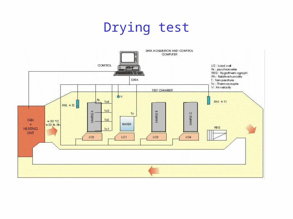
Drying test

ResultsK0 = 2.0 10-20 m2, Hr = 33%
Water content profiles
Change in mass with time

New theoretical model
Total water mass balance : 0)(
WWtm
vlw
Liquid mass flux : pSkTKW llrll
wl )(
)(
Constant gaz pressure hypothesis : pg = patm
Vapor mass flux : pDSTRΜW vvag
vv
Vapor pressure :
TRMpTpp
l
vcvsv exp)(
pDTDW lvpvTv =>

New theoretical model
scmDTT
pp
D vag
atmva /,217.0 2
0
88.1
Vapor diffusivity in air :
New adopted values : K0 = 1. 10-19 m2 λ’ = 0.4

New resultsK0 = 1.0 10-19 m2, Hr = 33%
Water content profiles
Change in mass with time

Step 1 – VE Experiment Phases 0,1
0102030405060708090
100
RH
[%
]
Applied RH
Mean of the RH of tunnelsensorsRH of outcoming air
Section SA3
In flow
RH-out
Water pan 1SA1
SB1 SC1SA2 SD1 SE
SC2 SB2SD2 SA4
SA3
Rear doors
Out flow
RH-outRH-in RH-1 RH-2
Water Pan 2
RH-in
Instrum ented section:SA : M in i P ie zo m e tersSB : H um id ity se ns orsSC : T D RsSD : Exten so m e te rsSE : G e oe le ctric
Forward doors
Legend :
R H-n : hyg ro m e te rRH-rRH-l
10 m
7 m
1,50 m
1,00 m
0,65 m
0,65 m
0,60 m
0,60 m
0,60 m
0,60 m
1,00 m
0,65 m
0,65 m
1,50 m
Phase 1

Step 1 – Hypothesis
• 2D plane strain model• Isotropic properties• Isotropic in-situ stresses• Constant temperature T=15°C• Same models and properties as for Step 0 • Influence of boundary conditions in tunnel• Phases 0 and 1 : calculation over 2120 days

Mesh
130 m

Initial and boundary conditions
σ = -3.2MPa, Pl = 1.21MPa
Pl = Hr (t)
or exchange
U . n = 0
Φl . n = 0
σ (0) and Pl (0)
affine in z
Sl (0) = 1
φ (0) = 0.16

Hr(t) in the tunnel
prescribed
Mean in SA3
Mean in tunnel

Exchange bc in the tunnel
► Inside the tunnel : nq hhext
rr)(
► Identification of α on the mean evaporated water mass
from the water pans :
● From 08/09/2003 to 28/01/2004 : Δm = 686.5 g
● Use of mean hrext
(t) in SA3 => α = 7.143 10-6 Kg/m2/s
-6000
-5000
-4000
-3000
-2000
-1000
0
18/0
7/02
03/0
2/03
22/0
8/03
09/0
3/04
25/0
9/04
13/0
4/05
30/1
0/05
18/0
5/06
04/1
2/06
Time [days from VE start]
Wat
er lo
st in
eac
h p
an [
gra
ms]
0
10
20
30
40
50
60
70
80
90
100WaterPan-1WaterPan-2

Base case
• No vapor diffusion
• K0 = 2. 10-20 m2 λ’ = 0.68
• Prescribed mean hr in the tunnel
• E = 6000 MPa

Extracted water masskg

Relative humidity – SB1
0,67 m
0,90 m
1,00 m
1,15 m
1.40 m

Relative humidity – SB2

Relative displacement – SD1mm

Relative displacement – SD2mm

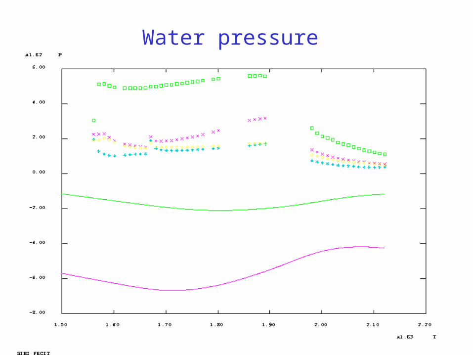
Water pressure kPa

Initial water pressure
-1000
-800
-600
-400
-200
0
200
400
600
800
1000
0.65 1.15 1.65 2.15 2.65
Distance from MT center [m]
pw
[k
Pa
]
28/07/2002 (horizontal)
28/07/2002 (45º)
28/07/2002 (vertical)
2 MPa
-12 MPa
0.

Variant 1
• Vapor diffusion accounted for
• K0 = 1. 10-19 m2 λ’ = 0.4
• Prescribed mean Hr in the tunnel
• E = 6000 MPa

Extracted water mass

Relative humidity – SB1

Relative humidity – SB2

Relative displacement – SD1

Relative displacement – SD2
Water pressure

Variant 2
• Vapor diffusion accounted for
• K0 = 1. 10-19 m2 λ’ = 0.4
• Exchange boundary condition in the tunnel• E = 1000 MPa

Extracted water mass

Relative humidity – SB1

Relative humidity – SB2

Relative displacement – SD1

Relative displacement – SD2

Water pressure

Conclusions
• Step 0 :– Accounting for vapor diffusion in a simplified way– Results similar to other teams
• Step 1 : – Preliminary results– Best results using vapor diffusion and exchange
condition– Over-estimated extracted water mass– Reduced rock stiffness

Thank you for your attention


