FP7-FCH-JU-2011-1 -303422 1 MATHRYCE Material Testing and Recommendations for Hydrogen Components under fatigue Deliverable D2.5 Existing codes and standards – First update Nature Report Dissemination PU D2.5 Existing codes and standards – First update Comparison of fatigue life in hydrogen gas according to different standards for a selected case study Foreseen submission date Project Month 21 Actual submission date Project Month 36 Author(s) Jader FURTADO – Air Liquide Takuya MATSUMOTO – Air Liquide Olivier BARDOUX– Air Liquide Béatrice FUSTER – Air Liquide Paolo BORTOT – TenarisDalmine Gianluca BASSANINI – TenarisDalmine Randy DEY – CCS Laurent BRIOTTET – CEA Version number for EC V1 Doc ID Code MATHRYCE_D2.5 Contract Start Date 2012-10-01 Duration 36 months Project Applicant CEA - LITEN FCH Joint Undertaking Collaborative Project Project funded by the European Commission
Transcript
FP7-FCH-JU-2011-1 -303422
1
MATHRYCE Material Testing and Recommendations for Hydrogen Components
under fatigue
Deliverable D2.5 Existing codes and standards – First update
Nature Report
Dissemination PU
D2.5 Existing codes and standards – First update Comparison of fatigue life in hydrogen gas according to different standards for a
selected case study
Foreseen submission date Project Month 21
Actual submission date Project Month 36
Author(s)
Jader FURTADO – Air Liquide Takuya MATSUMOTO – Air Liquide Olivier BARDOUX– Air Liquide Béatrice FUSTER – Air Liquide Paolo BORTOT – TenarisDalmine Gianluca BASSANINI – TenarisDalmine Randy DEY – CCS Laurent BRIOTTET – CEA
Version number for EC V1
Doc ID Code
MATHRYCE_D2.5
Contract Start Date 2012-10-01
Duration 36 months
Project Applicant CEA - LITEN
FCH Joint Undertaking Collaborative Project
Project funded by the European Commission
2
D2.5 – Existing codes and standards – First update Comparison of fatigue life in hydrogen gas according to different standards for a selected case study
Project Number FP7- FCH JU – 2011 – 1 - 303422
Project Acronym MATHRYCE
Title Material Testing and Recommendations for Hydrogen Components under fatigue
Deliverable N° D2.5
Due Date Project Month 21
Delivery Date Project Month 36
EXECUTIVE SUMMARY
In the present deliverable a comparison of a steel cylinder design, based on a selected case study, was carried out according to different international standards. Static design as well fatigue lives were compared using European EN13445, American ASME PVP Section VIII Divisions 2 and 3, and Japanese KHKS 0220 codes and standards. Design against hydrogen embrittlement was also investigated. The following conclusions can be made:
The effect of H2 on fatigue design life is not taken into account in codes ASME VIII Div.2, EN 13445 and KHKS 0220 codes. The only code that treats the accelerating effect of H2 on fatigue is ASME VIII Div.3 through its KD-10 article, which requires fatigue life assessment for seamless pressure vessels operating above 41 MPa H2 gas pressure, to be obtained by a fracture mechanics approach. In the case of cylinders used in this design exercise, they were designed for a MAWP of 28 MPa, therefore the application of KD-10 article is not mandatory;
KHKS 0220 does not consider the effect of hydrogen on fatigue design, but requires the use of fracture mechanics approach to assess crack propagation and LBB for ultra-high pressure devices, i.e. around 100 MPa;
Fracture mechanics analysis takes a central role as a tool to assess LBB in ASME VIII Div.3 and KHKS 0220. However, in EN13445 and ASME Section VIII Div.2 the use of fracture mechanics and LBB assessment are not considered;
Regarding fatigue analysis according to ASME VIII Div.2, EN 13445 and KHKS 0220, the differences in allowable cycles are due to differences in codes assessment methods. Despite these differences, the R effect in the determination of allowable cycles is important. High R value (R=0.5 and constant pmax) has almost no impact in the fatigue life of the cylinder. Although the effect of pmax was not calculated, it is known that it has an important effect on fatigue life and should be also verified.
Document Control
Title: D2.5 – Existing codes and standards – First update
Comparison of fatigue life in hydrogen gas according to different standards for a selected case study
Project: MATHRYCE
Type: Report Dissemination PU
The information contained in this report is subject to change without notice and should not be construed as a commitment by any members of the MATHRYCE Consortium. The MATHRYCE Consortium assumes no responsibility for the use or inability to use any procedure, protocol, which might be described in this report. The information is provided without any warranty of any kind and the MATHRYCE Consortium expressly disclaims all implied warranties, including but not limited to the implied warranties of merchantability and fitness for a particular use.
3
D2.5 – Existing codes and standards – First update Comparison of fatigue life in hydrogen gas according to different standards for a selected case study
Table of contents
1 REMINDER OF THE PROJECT MAIN OBJECTIVES ......................................................................................... 4
10 LIMITS OF EXISTING STANDARDS ................................................................................................................. 20
a) DBA is encouraged ..................................................................................................................................... 20 a) Restricted to some materials, e.g. ductile steels and steel castings and non-destructive testing requirements, such as accessibility to critical regions ......................................................................................... 20
D2.5 – Existing codes and standards – First update Comparison of fatigue life in hydrogen gas according to different standards for a selected case study
1 REMINDER OF THE PROJECT MAIN OBJECTIVES
The main objectives of the MATHRYCE project are centered on the development and dissemination for standardization of a methodology for the design of hydrogen high pressure metallic vessels and for their lifetime assessment that takes into account hydrogen-enhanced fatigue. This needs to be achieved without requiring full scale component testing under hydrogen as this is not practicable considering the expected lifecycle and equipment size. The project therefore targets the justification of an approach where lifetime assessment results from combining the hydraulic cycling performance of the component with the appropriate knowledge of the performance of the metallic material in hydrogen under cyclic loading.
This will be validated by comparing the lifetime prediction of a component calculated from the lab-scale tests to that obtained from large scale component tests. The analysis of the results, based on numerical simulations as well as on the scientific knowledge of the possible hydrogen embrittlement mechanisms, will allow to assess or to modify the proposed design methodology.
Once the testing method as well as the associated design methodology is validated, specific recommendations will be proposed for implementations in international standards.
To summarize, the main outcomes of the MATHRYCE project will be:
- The development of a reliable testing method to characterize materials exposed to hydrogen-enhanced fatigue,
- The experimental implementation of this testing approach, generating extensive characterization (microstructural and mechanical) of metallic materials for hydrogen service,
- The definition of a methodology for the design of metallic components exposed to hydrogen enhanced fatigue and for the assessment of their service lifetime; this methodology being liable to be recognized for pressure equipment regulation,
- The dissemination of this methodology, as a proposed approach for standardization,
- The dissemination of prioritized recommendations for implementations in international standards.
5
D2.5 – Existing codes and standards – First update Comparison of fatigue life in hydrogen gas according to different standards for a selected case study
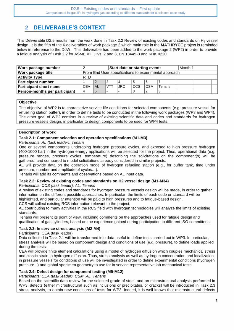
2 DELIVERABLE’S CONTEXT
This Deliverable D2.5 results from the work done in Task 2.2 Review of existing codes and standards on H2 vessel design. It is the fifth of the 6 deliverables of work package 2 which main role in the MATHRYCE project is reminded below in reference to the DoW. This deliverable has been added to the work package 2 (WP2) in order to provide a fatigue analysis of Task 2.2 for ASME VIII Divs. 2 and 3, EN 13445-3 and KHK 0220.
Work package number 2 Start date or starting event: Month 1
Work package title From End User specifications to experimental approach
Activity Type RTD
Participant number 1 2 3 4 5 6 7
Participant short name CEA AL VTT JRC CCS CSM Tenaris
Person-months per participant 4 5 - - 3 2 3
Objective
The objective of WP2 is to characterize service life conditions for selected components (e.g. pressure vessel for refuelling station buffer), in order to define tests to be conducted in the following work packages (WP3 and WP4). The other goal of WP2 consists in a review of existing scientific data and codes and standards for hydrogen pressure vessels design, in particular to design components to be used for WP4 tests.
Description of work
Task 2.1: Component selection and operation specifications (M1-M3) Participants: AL (task leader), Tenaris One or several components undergoing hydrogen pressure cycles, and exposed to high pressure hydrogen (400-1000 bar) in the hydrogen energy applications will be selected for the project. Thus, operational data (e.g. pressure ranges, pressure cycles, temperature) describing the solicitations on the component(s) will be gathered, and compared to model solicitations already considered in similar projects. AL will provide data on the operation mode of hydrogen refueling station (e.g., for buffer tank, time under pressure, number and amplitude of cycles…). Tenaris will add its comments and observations based on AL input data.
Task 2.2: Review of existing codes and standards on H2 vessel design (M1-M34) Participants: CCS (task leader), AL, Tenaris A review of existing codes and standards for hydrogen pressure vessels design will be made, in order to gather information on the different possible approaches. In particular, the limits of each code or standard will be highlighted, and particular attention will be paid to high pressures and to fatigue-based design. CCS will collect existing RCS information relevant to the project. AL contributing to many activities in the RCS field with hydrogen technologies will analyze the limits of existing standards. Tenaris will present its point of view, including comments on the approaches used for fatigue design and qualification of gas cylinders, based on the experience gained during participation to different ISO committees.
Task 2.3: In service stress analysis (M2-M4) Participants: CEA (task leader) Data collected in Task 2.1 will be transformed into data useful to define tests carried out in WP3. In particular, stress analysis will be based on component design and conditions of use (e.g. pressure), to define loads applied during the tests. CEA will provide finite element calculations using a model of hydrogen diffusion which couples mechanical stress and plastic strain to hydrogen diffusion. Thus, stress analysis as well as hydrogen concentration and localization in pressure vessels for conditions of use will be investigated in order to define experimental conditions (hydrogen pressure...) and global specimen geometry to use for in service representative lab mechanical tests.
Task 2.4: Defect design for component testing (M9-M12) Participants: CEA (task leader), CSM, AL, Tenaris Based on the scientific data review for the selected grade of steel, and on microstructural analysis performed in WP3, defects (either microstructural such as inclusions or precipitates, or cracks) will be introduced in Task 2.3 stress analysis, to obtain new conditions of tests for WP3. Indeed, it is well known that microstructural defects
6
D2.5 – Existing codes and standards – First update Comparison of fatigue life in hydrogen gas according to different standards for a selected case study
can play the role of stress concentrators, and initiate cracks in the presence of H2. In addition, stress analysis will be performed on components to be tested in WP4, with several sizes of defects. As in Task 2.3, CEA will provide finite element calculations to analyze stress and hydrogen distribution in pressure vessels including defects (microstructural...). The size of the defects will be defined using the microstructural characterization performed by CSM in the task 3.2. Thus, specimen geometries and experimental conditions for representative lab-scale mechanical tests will be defined. Two sizes of components will be tested, a small one (10 to 30 l) and a full scale one. The small size components will have to be representative of damages (initiation and crack growth) occurring in real size component while it allows to test in parallel numerous pressure vessels. CEA will also design a new specimen geometry for disk pressure tests including notches designed upon data collected in WT2.3. The purpose is to obtain a stress field at the notch tip close to that existing ahead of a crack in a pressure vessel during service. Finite element calculations will be used to realize such a design. If this goal is achieved, this should provide a quite simple mechanical test for studying hydrogen enhanced fatigue with a hydrogen cyclic charging. Such test would have the advantage to test the material under cycling hydrogen pressure whereas the other tests are carried out at a constant pressure. AL will also follow the designing of this new specimen for disk pressure test to make sure that it is easy enough to implement for industrial purpose. CSM will contribute to the stress analysis, by FEA, of components including defects. In particular the activity will have a twofold aim. On the one hand the stress analysis will aim to define stress concentration factors deriving from the presence of defects as inclusions or microstructural defects. The results of the microstructural characterization performed in WP3 will supply the input information on possible defects shape and dimensions to be considered in the activity. On the other hand a devoted stress analysis will be performed in order to define suitable dimensions for defect to be manufactured on components for full scale hydraulic tests planned in WP4. Tenaris will give its feedback on possible imperfections and/or microstructural heterogeneities which can be found in a pressure vessel below the typical NDT detection limit
Deliverables (month of delivery, Leader, Nature, Dissemination level)
D2.1 Operational data AL, R, CO, M3 D2.2 Existing codes and standards CCS, R, PU, M7 D2.3 Stress analysis CEA, R, CO, M4 D2.4 Defect design CEA, R, CO, M12 D2.5 Existing codes and standards – first update CEA, R, PU, M21 D2.6 Existing codes and standards – final update CEA, R, PU, M34
7
D2.5 – Existing codes and standards – First update Comparison of fatigue life in hydrogen gas according to different standards for a selected case study
3 Overview
This Deliverable D2.5 results from the work done in Task 2.2 Review of existing codes and standards on H2 vessel design. This deliverable was added to work package 2 (WP2) in order to provide a quantitative fatigue analysis of Task 2.2 for codes ASME VIII Divs. 2 and 3, EN 13445-3 and KHK 0220. The design of pressure vessels is usually carried out according to two design methodologies, e.g., design by formulae (DBF) or design by analysis (DBA). The latter is being encouraged by some national codes as the design can be verified through a detailed analysis of the structure behavior under loading conditions [1]. In the case of hydrogen refueling stations, the hydrogen buffer must be checked against the possibility of hydrogen-enhanced fatigue, a mechanical damage caused by hydrogen pressure cycling during the refueling of onboard vehicles’ hydrogen tanks [2-5]. Steel cylinders used for the containment of high pressure gas are designed as per EN 1964-1 standard [6], replaced by ISO 9809-1 [7], which requires the minimum number of 12,000 cycles at test pressure, where test pressure is 1.5 times the working pressure (420 bar). Since Rm (UTS) of the steel used for the cylinder manufacturing is less than 950 MPa, this material is considered compatible with hydrogen; therefore the same fatigue life is expected in H2 gas and in inert environment [8]. To design a pressure vessel against fatigue failure, as pointed out by Maddox [9], design codes rely on S-N curves in conjunction with Miner’s rule to assess variable amplitude loading. However, hydrogen-enhanced fatigue is still not fully addressed and is the aim of this report. We are interested in knowing how some national codes could deal with this fatigue design feature. Four pressure vessel codes and standards were addressed
1. ASME PVP Section VIII Div. 2 [10] 2. ASME PVP Section VIII Div. 3 [11], art. KD-10 [12]; 3. EN 13445-3 [13]; 4. KHKS 0220 [14].
The fatigue analysis was carried out through design by analysis (DBA), and the fracture mechanics approach was also used according to prescriptions given in ASME Section VIII, Div. 3 of the PVP code and KHK 0220 standard. The aim of D2.5 report is then to compare the fatigue life calculation of a hydrogen buffer according to these codes and standards for the selected case study.
4 Pressure vessel geometry and loading conditions
For this case study a pressure vessel, with a double neck, was used with material and dimensions given in Table 1. Table 1. Pressure vessel specifications and mechanical properties of the constitutive materials Pressure vessel description Mechanical
properties Vessel characteristics
OD (mm)
Min WT (mm)
Length (m)
Steel grade Rm
(MPa) Min Rp0,2
(MPa) MAWP (bar)
WP (bar)
220 9.1 1.3 34CrMo4 780890 600 280 280
Fatigue life was calculated for a 20-279 bar pressure range, corresponding to R-ratio equal to 0.07, and R equal to 0.50 (139.5 – 279 bar). The stress amplitude of all cycles was kept constant.
8
D2.5 – Existing codes and standards – First update Comparison of fatigue life in hydrogen gas according to different standards for a selected case study
5 ASME Section VIII, Div. 2 fatigue assessment
Calculations were carried out according to ASME VIII Div.2, Ed 2013 [10]. The static stress calculation was used to obtain the MAWP, while fatigue calculation was done according to ASME VIII Div.2 Part 5 (Design by Analysis), based on stress categorization with definition of membrane, bending and possible stress peaks. Figure 1 shows the block diagram of design calculation as per ASME Section VIII Div. 2. It has to be noted that, for this design case, ASME section VIII Div. 2 should be used since the requirements of art. KD-10 in ASME Section VIII Div. 3 are mandatory only when the MAWP exceeds 41 MPa.
5.1 Static calculations
Material elastic properties are required for static calculation. Since the 34CrMo4 steel is not available in the ASME code, it was decided to reference the ASME material SA 372 Gr.J Cl.70, which is similar in chemical composition, but using the mechanical properties declared for the 34CrMo4 steel as given in Table 1. The static calculation showed that, for a 9.1 mm minimum WT, the MAWP was 27.9 MPa, which is consistent with EN 1964-1 [6] calculation (withdrawn in 2010) and ISO 9809-1 [7]. Linear static analysis with stress categorization was carried out according to procedure shown in Figure 2, and a finite element analysis (FEA) was carried out as shown in Figure 3 in order to identify membrane, bending and critical stress locations.
Figure 1: A possible route of design against fatigue as per ASME Section VIII Div.2
9
D2.5 – Existing codes and standards – First update Comparison of fatigue life in hydrogen gas according to different standards for a selected case study
Figure 2: Procedure for stress categorization according to ASME Section VIII, Div.2
Figure 3 : Stress categorization lines (SCL) passing through the nodal location at which stresses
are higher
A complete 3D model of the vessel with tetrahedral solid elements was used [15] and Erreur ! Source du renvoi introuvable. shows the von Mises stresses in the vessel at the maximum pressure of 27.9 MPa.
10
D2.5 – Existing codes and standards – First update Comparison of fatigue life in hydrogen gas according to different standards for a selected case study
5.2 Fatigue calculations
No fatigue strength reduction factor was considered in the calculation since no welds are present. The fatigue curve to use in fatigue analysis is reported in Annex 3.F of ASME VIII Div.2. The design number of cycles N was computed according to:
𝑁 = 10𝑋 [1]
𝑥 =𝐶1+𝐶3𝑌+𝐶5𝑌2+𝐶7𝑌3+𝐶9𝑌4+𝐶11𝑌5
1+𝐶2𝑌+𝐶4𝑌2+𝐶6𝑌3+𝐶8𝑌4+𝐶10𝑌5 [2]
𝑌 = ((𝑆𝑎
𝐶𝑢𝑠) (
𝐸𝐹𝐶
𝐸𝑇)) [3]
based on the calculated Sa, derived from stress categorization and equivalent stress range as given in section 5.5.3 of the standard. The coefficients Ci depend on the materials used and are given in Table 3-F.2 of the standard. The resulting number of cycles was N = 1,851,566 cycles for R-ratio equal to 0.07. A similar calculation was performed for R-ratio equal to 0.5.
Figure 4. Von Mises stress on cylinder at MAWP
11
D2.5 – Existing codes and standards – First update Comparison of fatigue life in hydrogen gas according to different standards for a selected case study
The fatigue design methodology based on ASME Section VIII Div.3 [11] is given in Figure 4. Calculations were carried out according to ASME VIII Div.3, art. KD-10 Ed. 2013 [12]. In this case only, fatigue calculation was carried out according to the rules given in article KD-10, where a fracture mechanics approach is required. Art. KD-10 references stress intensity factors solutions given in API579-1/ASME FFS1 [16]. The solution “KCSCLE1 - Cylinder surface crack, longitudinal direction - semi elliptical shape, internal pressure”, was selected for this calculation. Such stress intensity factor solution is valid up to a crack depth equal to 80% of the WT. Fatigue crack growth ratio (FCGR) should be experimentally determined for the R-ratio of interest. Since FCGR data were not available for the investigated steel at the required MAWP (maximum allowable wall pressure), they were estimated from data given in [17] at R=0.1. For a SCM 435 (Cr-Mo) steel, the authors provide FCGR in air as:
𝑑𝑎
𝑑𝑁= 3.48(10)−12(𝛥𝛫)3.07 [4]
Authors also provide a coefficient to correct FCGR depending on the H2 gas pressure. This acceleration factor is given by equation 5 and can be correlated with FGGR in air through equation 5:
𝜂 = 7.12(𝑝)0.34 [5] where:
𝜂 =(
𝑑𝑎
𝑑𝑁)
𝐻2
(𝑑𝑎
𝑑𝑁)
𝑎𝑖𝑟
[6]
Based on the previous equations, a FCGR curve was estimated for a 280 bar H2 gas pressure:
𝑑𝑎
𝑑𝑁= 8(10)−11(𝛥𝛫)3.07 [7]
Art. KD-10 also requires to experimentally determine the threshold stress intensity factor for crack propagation according to ASTM E1681 [18]. In the present case, fracture toughness data obtained under rising load experimental conditions were available. It is well known that such data are lower compared to crack arrest threshold conditions [18]. Data from [1] indicated a lower bound KIH = 64 MPa*m1/2 which was used in the present calculation. The assumed initial crack depth was 0.00 mm with an aspect ratio a/2c = 1/3 as prescribed by art. KD-10. The prescribed allowable number of cycles is the lesser of:
half the number of cycles to propagate the crack from initial size to the critical crack depth.
the number of cycles to propagate a crack from the initial size to the allowable crack size. The allowable crack depth is the lesser of 25% of the section thickness or 25% of the critical crack depth, with the latter calculated using the FAD (Failure assessment diagram) concept (see section 9.4.3 of API 579).
12
D2.5 – Existing codes and standards – First update Comparison of fatigue life in hydrogen gas according to different standards for a selected case study
The resulting FAD is shown in Figure 5, where it is clear that all the crack growth increments fall within the acceptable region without intersecting the limit curve. The resulting number of cycles was N=4,500 cycles.
Figure 4 : A possible route of design against fatigue according to ASME Section VIII Div.3
Figure 5 : FAD for the investigated cylinder including crack growth increment
Acceptable region
Unacceptable region
13
D2.5 – Existing codes and standards – First update Comparison of fatigue life in hydrogen gas according to different standards for a selected case study
7 EN 13445 fatigue assessment
Figure 6 shows schematically the design methodology proposed by the European standard EN13445 [13]. If the pressure component is expected to be subject in service to less than 500 pressure cycles, it is not required to check the design against fatigue damage. In our case study, the investigated steel cylinder requires a fatigue analysis. EN13445 proposes two alternatives for such calculations, a simplified route according to clause 17 or a detailed fatigue analysis prescribed by clause 18 of the standard. Similarly to the static calculations as per ASME VIII Div.2 code, static calculation was used to obtain the MAWP. However, the allowable number of fatigue cycles was obtained through the detailed fatigue analysis route, and the fatigue check according to the simplified assessment methodology.
Figure 6 : A possible route to fatigue design analysis as per EN 13445-3 [13].
7.1 Static calculations
The material elastic properties required for static calculation are provided in Tables 1 and 2 for the Cr-Mo steel used for the manufacturing of the selected pressure vessel. Finite element analysis was performed in the same way as in Section 6. Steel chemical composition was in accordance with EN 10083-1. Table 2 : Mechanical properties of 34CrMo4 Material: 34CrMo4 (EN10083-1)
Temperatures °C -50 to +20 50 Modulus of elasticity MPa 201000 201000 Yield stress, Rp0.2/T MPa 600 600 Tensile stress, Rm/20 MPa 780 890 Allowable stress (f) MPa 325 325 Density Kg/dm
3 7.85 7.85
Poisson’s ratio 0.3 0.3
14
D2.5 – Existing codes and standards – First update Comparison of fatigue life in hydrogen gas according to different standards for a selected case study
The allowable stress (f) was calculated according to EN13445-3 following Equation 8:
𝑓 = 𝑚𝑖𝑛 (𝑅𝑝0.2/𝑇
1.5;
𝑅𝑚/20
2.4) [8]
In order to carry out the static stress analysis it was chosen also to use the calculation route with stress categorization. The stress categories and limits of stress intensity are in accordance with [C2], Table 3 – Illustration of assessment criteria (Table C.3 of EN 13445-3). Allowable stress is divided in:
Primary general membrane stress (Pm): Pm ≤ S
Primary local membrane stress (PL): PL ≤ 1.5*S
Primary local membrane (PL) + primary local bending (Pb): (PL+PB) ≤ 1.5*S
D2.5 – Existing codes and standards – First update Comparison of fatigue life in hydrogen gas according to different standards for a selected case study
7.2 Fatigue calculations
According to EN13445-3 Paragraph 18.7, the assessment of fatigue analysis on seamless components
is based on effective equivalent stress, f, and the same loading conditions defined in Section 4 were employed. These effective equivalent total stresses can be evaluated either from structural stresses or from total stresses: From structural stress:
𝛥𝜎𝑓 = 𝐾𝑓 ∗ 𝛥𝜎𝑒𝑞,𝑠𝑡𝑟𝑢𝑐𝑡 [9]
From total stress:
𝛥𝜎𝑓 = 𝐾𝑓 ∗ 𝛥𝜎𝑒𝑞,𝑡𝑜𝑡𝑎𝑙 [10]
Since a detailed stress analysis is performed, the evaluation from total stress is used. The effective stress concentration factor Kf is given by:
𝐾𝑓 = 1 + (1.5(𝐾𝑡−1)
1+0.5𝑚𝑎𝑥{1;𝐾𝑡𝛥𝜎𝑒𝑞,𝑠𝑡𝑟𝑢𝑐𝑡
𝛥𝜎𝐷}) [11]
𝑓𝑢 = 𝑓𝑠 ∗ 𝑓𝑒 ∗ 𝑓𝑚 ∗ 𝑓𝑡 [12]
𝑁 = (4.6∗104
∆𝜎𝑓
𝑓𝑢−0.63∗𝑅𝑚+11.5
)
2
[13]
𝑁 = (4.6∗104
∆𝜎𝑅−0.63∗𝑅𝑚+11.5)
2
[14]
Where eq,struct is the structural equivalent stress range corrected to account for plasticity correction according to Para. 18.8. The fatigue check is based on the equivalent stress range and for a multi-axial stress state, on the maximum variation in time of the principal stresses. The components stresses and categorized primary + secondary stresses, for all load cases, are extracted from SOLIDWORKS database and used as input for EN13445-3 fatigue procedure as described at Paragraph 18.11. The Stress Categorization Line (SCLs) considered for primary + secondary stress categorization are passing through the nodal locations at which fatigue damage is given in Figure 3. The resulting number of cycles was N=173,551 cycles for R-ratio equal to 0.07, and N=1.0 x10⁸ cycles for R-ratio equal to 0.50.
16
D2.5 – Existing codes and standards – First update Comparison of fatigue life in hydrogen gas according to different standards for a selected case study
8 KHK S0220 fatigue assessment
The Japanese code KHKS 0220 is applied to the design of components used for the containment of ultra-high pressure gas, excluding hydrogen. The design methodology for fatigue is presented in Figure
7. It allows carrying out the fatigue analysis as per ASME VIII Div.2 and EN 13445-3, but it is coupled with a damage tolerance analysis, and needs leak before break (LBB) assessment and crack growth analysis based on fracture mechanics. This later analysis is similar to the one established by the ASME VIII Div.3, art. KD10 code case, which is required to address high pressure hydrogen containment higher than 41 MPa.
Figure 7 : Fatigue design methodology according to KHKS 0220 code and corresponding code sections
8.1 Static and fatigue calculations
In the KHK S0220 code, in order to address the design of ultra-high pressure facilities (around 100 MPa), the safety factor (f) used in the calculation of sound wall thickness and maximum allowed pressure was dropped from 4 to 2.4, similarly to code ASME VIII Div.2 and EN13445, and the design by formula was replaced by the design by analysis. The maximum allowed pressure is determined through the equation:
𝑃𝑎𝑙𝑙 = (1
𝑓)
(𝑆𝑦+𝑆𝑢)
2 [15]
where Pall is the maximum allowable pressure, f is the safety factor, Sy is the yield strength, Su the ultimate tensile stress (or Rm).
17
D2.5 – Existing codes and standards – First update Comparison of fatigue life in hydrogen gas according to different standards for a selected case study
The sound wall thickness is determined through the equation:
𝑡𝑟 = (𝐷𝑖
2) {𝑒𝑥𝑝 [
√3𝑓𝑃
(𝑆𝑦+𝑆𝑢)] − 1} [16]
where tr is the minimum thickness required for the design pressure P Fatigue analysis in KHK S0220 needs the determination of stress amplitude, which is given by equation 17:
𝑆𝑎𝑙𝑡 =𝐾2
𝐾2−1(𝑃𝑢 − 𝑃𝑙) [17]
where: Salt is the stress amplitude, K is the diameter ratio, Pu is the maximum working pressure and Pl is the minimum working pressure. Equation 17 is further corrected to account for temperature and surface finishing effect.
𝑆𝑎𝑙𝑡′ = 𝑆𝑎𝑙𝑡 (
𝐸
𝐸𝑑) 𝛼 [18]
where: E/Ed is the ratio of modulus of elasticity, which depends on material and working temperature, α is the stress concentration factor due to surface roughness (Rz). If Rz is less than 3.2 µm, α is taken as unity. For these working conditions E/Ed=1.020, which gives S’alt equal to 181.1 MPa. For this corrected stress range amplitude, the number of allowable cycles of 255,714 cycles was determined from a design S-N fatigue curve of ferritic steel with tensile strength less than 895 MPa at RT.
LBB criteria assessment The LBB criteria are satisfied if equations 19 and 20 are fulfilled. This LBB analysis shall ensure that in the case of a through thickness crack growth the rupture will be preceded by leakage and no burst of the vessel will occur. Two conditions are required to fulfill such requirement:
𝐾𝐼 < 𝐾𝐼𝐶 [19]
0.2𝑡 < (𝐾𝐼𝐶
𝑆𝑦)
2
[20]
where KI is the stress intensity factor at the tip of a specified defect type present in the component; KIC is the plain strain fracture toughness. KI is calculated for crack depth equal to 0.8t (t is the vessel thickness) for the semi-elliptical defect shown in Figure 9. The approach is similar to the one proposed by ASME VIII Div.3, art. KD-10 code case, described earlier in Section 7.
Figure 8 : Semi-elliptical defect schematic
18
D2.5 – Existing codes and standards – First update Comparison of fatigue life in hydrogen gas according to different standards for a selected case study
KI is determined through Equation 21 and the shape factor (Q) is equal to 1.74 following Equation 22.
𝐾𝐼 = [(𝐴0 + 𝐴𝑝)𝐺0 + 𝐴1𝐺1 + 𝐴2𝐺2 + 𝐴3𝐺3]√𝜋𝑎
𝑄 [21]
𝑄 = 1 + 4.593 (𝑎
𝑙)
1.65
[22]
where: A0 ~ A3: coefficients Ap: pressure on crack surface (= 28 MPa) Q: parameter on crack shape G0 ~ G3: free surface correction factor a/l: aspect ratio (= 1/3) a: crack depth (= 0.8t) l: crack length (= 2c) c: half crack length For the calculation of Ai coefficients, the stress distribution s is approximated by Equation 23.
𝜎 = 𝐴0 + 𝐴1 (𝑥
𝑎) + 𝐴2 (
𝑥
𝑎)
2
+ 𝐴3 (𝑥
𝑎)
3
[23]
Where: x is the distance from the surface (0≤x≤a). If the stress is only generated by pressure and K is in the range of 1.2≤K≤3, stress distribution is approximated by Equation 24.
𝜎 = 𝐴0′ + 𝐴1
′ (𝑥
𝑡) + 𝐴2
′ (𝑥
𝑡)
2
+ 𝐴3′ (
𝑥
𝑡)
3
[24]
Fatigue crack growth analysis It was based on paper of Yamabe et al [17] from Kyushu University, used also for the calculation of ASME VIII Div.3 KD-10. It was assumed that the initial crack growth was 0.500 mm, imposed by the KHK S0220 code, as the minimum size detectable by non-destructive techniques. The same propagation equations were used. The number of fatigue cycles in high pressure hydrogen was found to be 2,581 cycles.
19
D2.5 – Existing codes and standards – First update Comparison of fatigue life in hydrogen gas according to different standards for a selected case study
9 Discussion
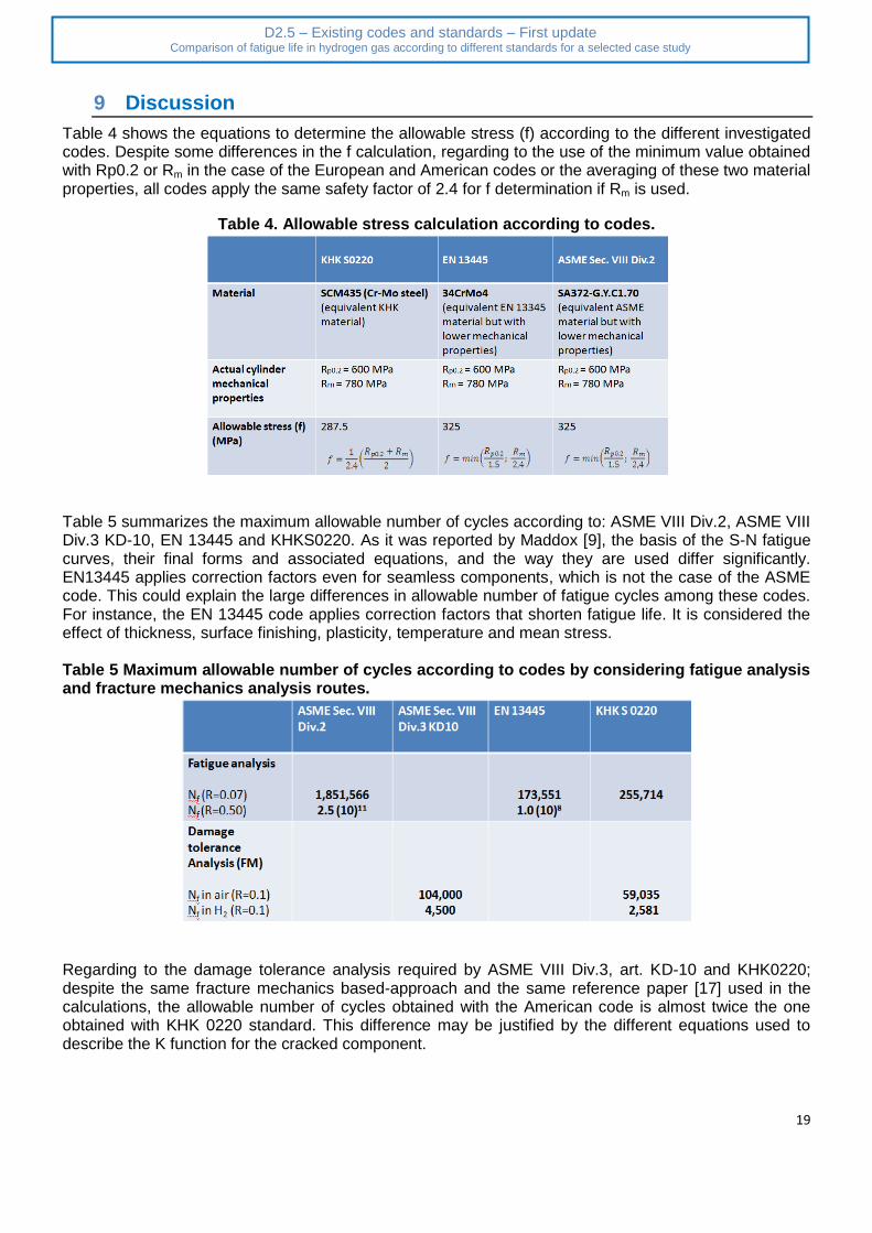
Table 4 shows the equations to determine the allowable stress (f) according to the different investigated codes. Despite some differences in the f calculation, regarding to the use of the minimum value obtained with Rp0.2 or Rm in the case of the European and American codes or the averaging of these two material properties, all codes apply the same safety factor of 2.4 for f determination if Rm is used.
Table 4. Allowable stress calculation according to codes.
Table 5 summarizes the maximum allowable number of cycles according to: ASME VIII Div.2, ASME VIII Div.3 KD-10, EN 13445 and KHKS0220. As it was reported by Maddox [9], the basis of the S-N fatigue curves, their final forms and associated equations, and the way they are used differ significantly. EN13445 applies correction factors even for seamless components, which is not the case of the ASME code. This could explain the large differences in allowable number of fatigue cycles among these codes. For instance, the EN 13445 code applies correction factors that shorten fatigue life. It is considered the effect of thickness, surface finishing, plasticity, temperature and mean stress. Table 5 Maximum allowable number of cycles according to codes by considering fatigue analysis and fracture mechanics analysis routes.
Regarding to the damage tolerance analysis required by ASME VIII Div.3, art. KD-10 and KHK0220; despite the same fracture mechanics based-approach and the same reference paper [17] used in the calculations, the allowable number of cycles obtained with the American code is almost twice the one obtained with KHK 0220 standard. This difference may be justified by the different equations used to describe the K function for the cracked component.
20
D2.5 – Existing codes and standards – First update Comparison of fatigue life in hydrogen gas according to different standards for a selected case study
10 Limits of existing standards
Table 6 shows the advantages and drawbacks of the analyzed standards. For the design of pressure vessels for the containment of high pressure hydrogen, only ASME VIII Div.3, through the KD-10 code case article addresses the embrittling effect of hydrogen with the deterioration of its mechanical properties. Other codes don’t do it. Table 6. Advantages and drawbacks of analyzed codes and standards
Code H2 fatigue design method
Advantages Drawbacks
ASME VIII Div.2 [2], [10] a) Based on S-N curves
a) Simple method a) It does not address hydrogen embrittlement effect on fatigue
ASME VIII Div.3, art. KD-10 [11], [12]
a) Damage tolerance analysis required: LBB and FCG assessments
a) Address specifically high pressure hydrogen applications for non welded vessels from P≥41 MPa, and 17 MPa for welded vessels
b) Classical lab scale tests, but under H2
a) FCG (fatigue crack growth) is overestimated for low ∆K [20]
b) For this class of Cr-Mo steels the KIH at constant load is higher than KIH obtained at rising loading [20]
c) Testing frequency (f) is low (f=0.1 Hz), the amount of required tests is high (3 tests per heat), and the cracking propagation measuring device is subjected to signal drifts during testing
EN13445 [1], [2], [13] a) DBA is encouraged
b) Fatigue analysis is based on S-N curves
a) It is very flexible, allows for any combination of actions, such as imposed pressures, forces, displacements and imposed temperatures, any geometries and geometrical details
a) Restricted to some materials, e.g. ductile steels and steel castings and non-destructive testing requirements, such as accessibility to critical regions
b) It does not address hydrogen embrittlement effect on fatigue
KHK 0220 [14], [17] a) DBA required b) Fatigue analysis is
based on S-N curves
c) Damage tolerance
a) Classical lab scale tests, but under H2
a) Vessel design still needs previous approval by KHK 0220
b) It does not
21
D2.5 – Existing codes and standards – First update Comparison of fatigue life in hydrogen gas according to different standards for a selected case study
analysis required: LBB and fatigue crack propagation assessments
d) Full scale tests under H2 pressure required
address hydrogen embrittlement effect on fatigue
11 Conclusion
A fatigue analysis was carried out, on the cylinder geometry used during the project, following codes: ASME VIII Div.2, ASME VIII Div.3, EN 13445 and KHKS 0220. The following observations can be made:
The effect of H2 on fatigue design life is not taken into account in codes ASME VIII Div.2, EN 13445 and KHKS 0220 codes. The only code that treats the accelerating effect of H2 on fatigue is ASME VIII Div.3 through its KD-10 article, which requires fatigue life assessment for seamless pressure vessels operating above 41 MPa H2 gas pressure, to be obtained by a fracture mechanics approach. In the case of cylinders used in this design exercise, they were designed for a MAWP of 28 MPa, therefore the application of KD-10 article is not mandatory;
KHKS 0220 does not consider the effect of hydrogen on fatigue design, but requires the use of fracture mechanics approach to assess crack propagation and LBB for ultra-high pressure devices, i.e. around 100 MPa;
Fracture mechanics analysis takes a central role as a tool to assess LBB in ASME VIII Div.3 and KHKS 0220. However, in EN13445 and ASME Section VIII Div.2 the use of fracture mechanics and LBB assessment are not considered;
Regarding to fatigue analysis according to ASME VIII Div.2, EN 13445 and KHKS 0220, the differences in allowable cycles are due to differences in codes assessment methods. Despite these differences, the R effect in the determination of allowable cycles is important. High R value (R=0.5) has almost no impact in the fatigue life of the cylinder. Although the effect of pmax was not calculated, it is know that it has an important effect of fatigue life and should be also verified.
22
D2.5 – Existing codes and standards – First update Comparison of fatigue life in hydrogen gas according to different standards for a selected case study
12 References
[1] Zeman, J. L., Pressure Vessel Design-The Direct Route, Elsevier, Amsterdam, 2003
[2] Murakami Y, Matsuoka S, Kondo Y, Nishimura S. Mechanism of Hydrogen Embrittlement and Guide for Fatigue Design. 3, Yokendo Ltd., Tokyo, Japan (in Japanese); 2012.
[3] Gangloff, R., Somerday B.P., Gaseous hydrogen embrittlement of materials in energy technologies, Vol. 1, Woodhead Publishing 2012.
[4] Macadre A, Artamonov M,Matsuoka S, Furtado J. Effects of hydrogen pressure and test frequency on fatigue crack growth properties of Ni-Cr-Mo steel candidate for a storage cylinder of a 70MPa hydrogen filling station. Engineering FractureMechanics 2011; 78: 3196-3211.
[5] Briottet L, Moro I, Escot M, Furtado J, Bortot P, Tamponi GM, Solin J, Odemer G, Blanc C, Andrieu E. Fatigue crack initiation and growth in a CrMo steel under hydrogen pressure. International Journal of Hydrogen Energy 2015.
[6] EN1964-1 Transportable gas cylinders. Specification for the design and construction of refillable transportable seamless steel gas cylinders of water capacities from 0,5 litre up to and including 150 litres. Cylinders made of seamless steel with an Rm value of less than 1100 MPa.
[7] ISO9801-1 Gas cylinders-Refillable seamless steel gas cylinders-Design, construction and testing-Part 1: Quenched and tempered steel cylinders with tensile strength less than 1100 MPa.
[8] NF EN ISO 11114-4. Transportable gas cylinders - Compatibility of cylinder and valve materials with gas contents-Part 4: Test methods for selecting metallic materials resistant to hydrogen embrittlement, AFNOR Association Française de Normalisation, Paris, France, 2006.
[9] Maddox, S., Comparison of the ASME, BS and CEN fatigue design rules for pressure vessels, TWI, Cambridge, UK. Internet access on 14/06/2013, www.twi.co.uk.
[10] ASME Section VIII Div. 2, 2015
[11] ASME Section VIII Div. 3, 2015
[12] ASME, Article KD-10. Special requirements for vessels in high pressure gaseous hydrogen transport and storage service. ASME Sec. VIII, Div. 3, ASME, NY; 2015.
[13] EN 13445-3 Unfired pressure vessels – Part 3: Design, 2014.
[14] KHK S 0220, 2010, KHK Standard for Pressure Equipments containing Ultra High Pressure Gas, The High Pressure Gas Safety Institute of Japan.
[15] Solid Works Simulation, 2013
[16] API 579 – ASME FFS-1, 2007.
[17] Junichiro Yamabe, Hisatake Itoga, Tohru Awane, Hisao Matsunaga, Shigeru Hamada and Saburo Matsuoka, Fatigue Life and leak before break assessments of Cr-Mo steel pressure vessels with high pressure gaseous hydrogen, PVP2014-28604
[18] ASTM E1681-03 - Standard test method for determining threshold stress intensity factor for environment-assisted cracking of metallic materials. Annual Book of ASTM Standards, ASTM International,West Conshohocken, PA.
[19] Nibur, Kevin A.; Somerday, Brian P.; Marchi, Chris San; Foulk, James W.; Dadfarnia, Mohsen; Sofronis, Petros, The Relationship Between Crack-Tip Strain and Subcritical Cracking Thresholds for Steels in High-Pressure Hydrogen Gas, Metallurgical and Materials Transactions A, Volume 44, Issue 1, pp.248-269.
[20] Somerday, Brian; Measurements of Subcritical Cracking Thresholds and Fatigue Crack Growth Rates for Steels in H2 Gas, Mathryce project meeting,, Joint Research Center, Petten, Netherlands, October, 10, 2014.