» Zone Offroad Products • 491 W. Garfield Ave., Coldwater, MI 49036 • 888.998.ZONE • www.zoneoffroad.COM Read and understand all instructions and warnings prior to installation of product and operation of vehicle. Zone Offroad Products recommends this system be installed by a professional technician. In addition to these instructions, profes- sional knowledge of disassembly/ reassembly procedures and post installation checks must be known. Minimum tool requirements include the following: Assorted metric and standard wrenches, hammer, hydraulic floor jack and a set of jack stands. See the "Special Tools Required" section for additional tools needed to complete this installation properly and safely. » PRODUCT SAFETY WARNING Certain Zone Suspension Products are intended to improve off-road performance. Modifying your vehicle for off-road use may result in the vehicle handling differently than a factory equipped vehicle. Extreme care must be used to prevent loss of control or vehicle rollover. Failure to drive your modified vehicle safely may result in serious injury or death. Zone Offroad Products does not recom- mend the combined use of suspension lifts, body lifts, or other lifting devices. You should never operate your modified vehicle under the influence of alcohol or drugs. Always drive your modified vehicle at re- duced speeds to ensure your ability to control your vehicle under all driving conditions. Always wear your seat belt. » TECHNICAL SUPPORT www.zoneoffroad.com may have additional information about this product including the lat- est instructions, videos, photos, etc. Send an e-mail to [email protected]detailing your issue for a quick response. 888.998.ZONE Call to speak directly with Zone tech support. » PRE-INSTALLATION NOTES 1. Special literature required: OE Service Manual for model/year of vehicle. Refer to manual for proper disassembly/reassembly procedures of OE and related components. 2. Adhere to recommendations when replacement fasteners, retainers and keepers are called out in the OE manual. 3. Larger rim and tire combinations may increase leverage on suspension, steering, and related components. When selecting combinations larger than OE, consider the ad- ditional stress you could be inducing on the OE and related components. 4. Post suspension system vehicles may experience drive line vibrations. Angles may require tuning, slider on shaft may require replacement, shafts may need to be length- ened or trued, and U-joints may need to be replaced. 5. Secure and properly block vehicle prior to installation of Zone Offroad Products. Al- ways wear safety glasses when using power tools. 6. If installation is to be performed without a hoist, Zone Offroad Products recommends rear alterations first. 7. Due to payload options and initial ride height variances, the amount of lift is a base fig- ure. Final ride height dimensions may vary in accordance to original vehicle attitude. Always measure the attitude prior to beginning installation. Difficulty Level easy 1 2 3 4 5 difficult Estimated installation: 8 hours Tire/Wheel Fitment -6" system: 37x12.50x17 w/ 4-1/2" Backspacing -6" system: 37 x 12.50 x 20 w/ 4-1/2"~5" Backspacing -4" system: 35 x 12.50x17 w/ 4-1/2" Backspacing -4" system: 35 x 12.50 x 20 w/ 4-1/2"~5" Backspacing -Stock 20 rims can be reinstalled with stock tire size -Stock 17" rims cannot be rein- stalled after installation Other Notes: You cannot install this kit in con- junction with a spacer kit to get 8 inches of lift. It will not work. rev021318 D2612 Installation Instructions 2012-2017 Dodge 1500 4wd 4" and 6" Suspension Systems
Transcript
»Zone Offroad Products • 491 W. Garfield Ave., Coldwater, MI 49036 • 888.998.ZONE • www.zoneoffroad.com
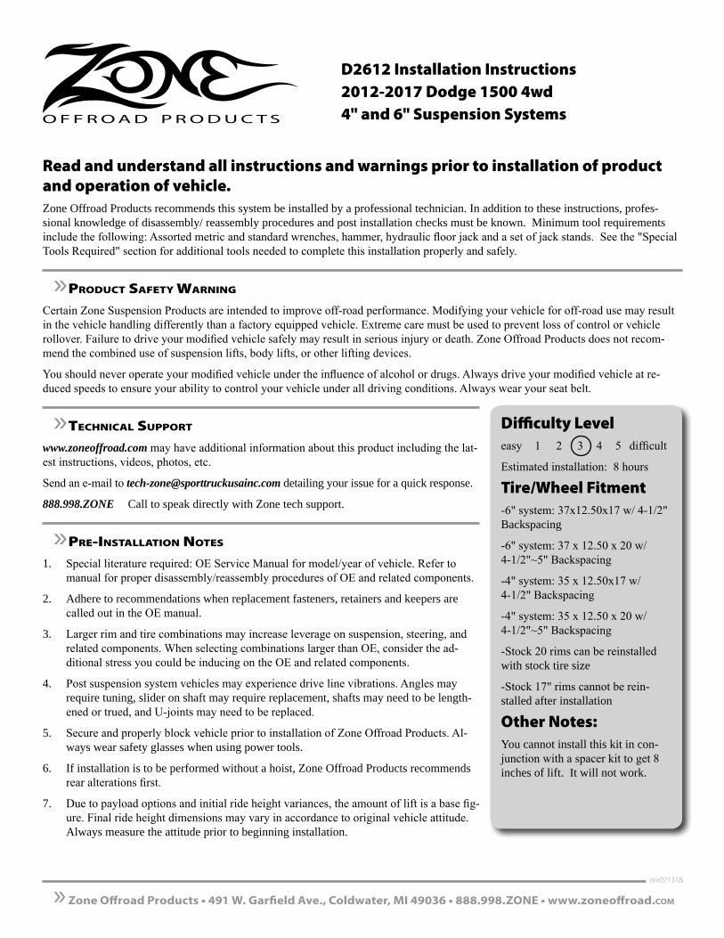
Read and understand all instructions and warnings prior to installation of product and operation of vehicle.Zone Offroad Products recommends this system be installed by a professional technician. In addition to these instructions, profes-sional knowledge of disassembly/ reassembly procedures and post installation checks must be known. Minimum tool requirements include the following: Assorted metric and standard wrenches, hammer, hydraulic floor jack and a set of jack stands. See the "Special Tools Required" section for additional tools needed to complete this installation properly and safely.
»Product Safety Warning
Certain Zone Suspension Products are intended to improve off-road performance. Modifying your vehicle for off-road use may result in the vehicle handling differently than a factory equipped vehicle. Extreme care must be used to prevent loss of control or vehicle rollover. Failure to drive your modified vehicle safely may result in serious injury or death. Zone Offroad Products does not recom-mend the combined use of suspension lifts, body lifts, or other lifting devices.
You should never operate your modified vehicle under the influence of alcohol or drugs. Always drive your modified vehicle at re-duced speeds to ensure your ability to control your vehicle under all driving conditions. Always wear your seat belt.
»technical SuPPort
www.zoneoffroad.com may have additional information about this product including the lat-est instructions, videos, photos, etc.
Send an e-mail to [email protected] detailing your issue for a quick response.
888.998.ZONE Call to speak directly with Zone tech support.
»Pre-inStallation noteS
1. Special literature required: OE Service Manual for model/year of vehicle. Refer to manual for proper disassembly/reassembly procedures of OE and related components.
2. Adhere to recommendations when replacement fasteners, retainers and keepers are called out in the OE manual.
3. Larger rim and tire combinations may increase leverage on suspension, steering, and related components. When selecting combinations larger than OE, consider the ad-ditional stress you could be inducing on the OE and related components.
4. Post suspension system vehicles may experience drive line vibrations. Angles may require tuning, slider on shaft may require replacement, shafts may need to be length-ened or trued, and U-joints may need to be replaced.
5. Secure and properly block vehicle prior to installation of Zone Offroad Products. Al-ways wear safety glasses when using power tools.
6. If installation is to be performed without a hoist, Zone Offroad Products recommends rear alterations first.
7. Due to payload options and initial ride height variances, the amount of lift is a base fig-ure. Final ride height dimensions may vary in accordance to original vehicle attitude. Always measure the attitude prior to beginning installation.
-6" system: 37 x 12.50 x 20 w/ 4-1/2"~5" Backspacing
-4" system: 35 x 12.50x17 w/ 4-1/2" Backspacing
-4" system: 35 x 12.50 x 20 w/ 4-1/2"~5" Backspacing
-Stock 20 rims can be reinstalled with stock tire size
-Stock 17" rims cannot be rein-stalled after installation
Other Notes:You cannot install this kit in con-junction with a spacer kit to get 8 inches of lift. It will not work.
rev021318
D2612 Installation Instructions2012-2017 Dodge 1500 4wd4" and 6" Suspension Systems
D2612 Installation - pg. 2
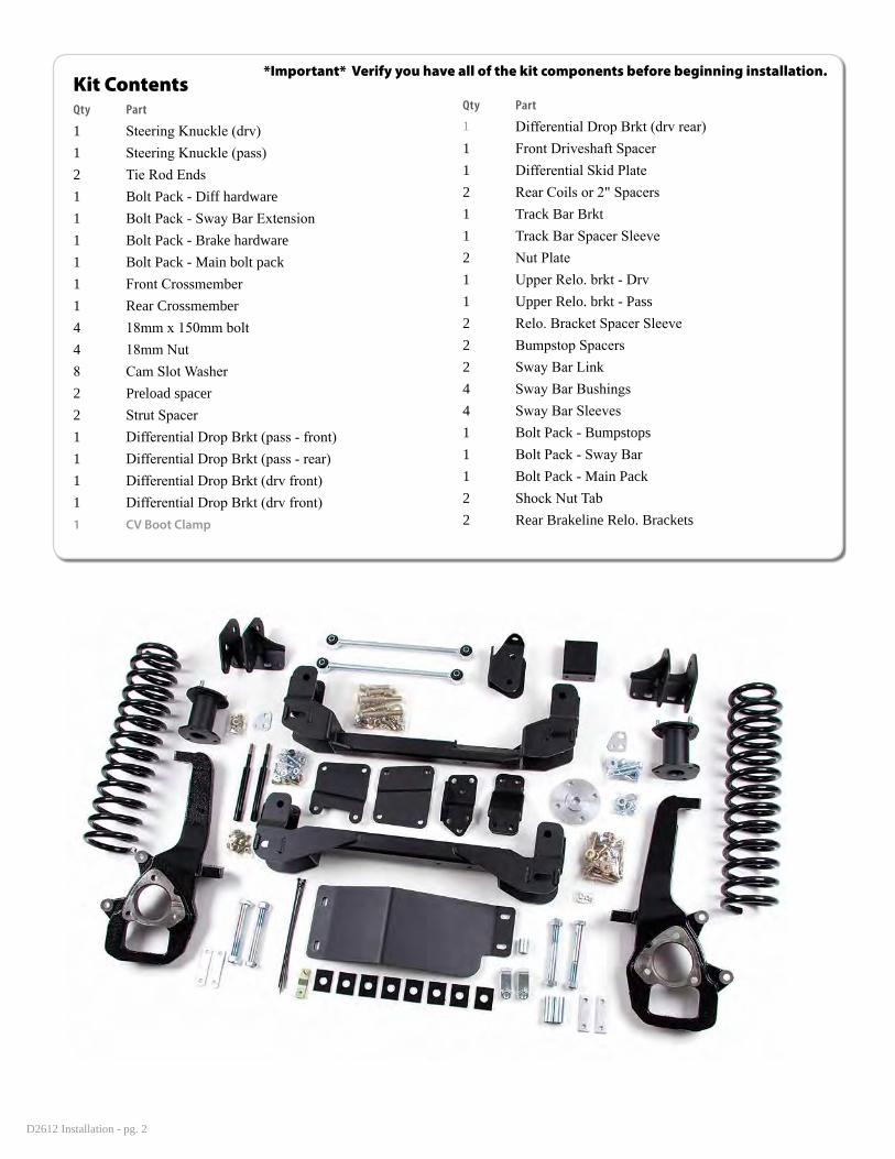
Kit ContentsQty Part
1 Steering Knuckle (drv)1 Steering Knuckle (pass)2 Tie Rod Ends1 Bolt Pack - Diff hardware1 Bolt Pack - Sway Bar Extension1 Bolt Pack - Brake hardware1 Bolt Pack - Main bolt pack1 Front Crossmember 1 Rear Crossmember 4 18mm x 150mm bolt4 18mm Nut8 Cam Slot Washer2 Preload spacer2 Strut Spacer1 Differential Drop Brkt (pass - front)1 Differential Drop Brkt (pass - rear)1 Differential Drop Brkt (drv front)1 Differential Drop Brkt (drv front)1 CV Boot Clamp
Qty Part
1 Differential Drop Brkt (drv rear)1 Front Driveshaft Spacer1 Differential Skid Plate 2 Rear Coils or 2" Spacers 1 Track Bar Brkt1 Track Bar Spacer Sleeve2 Nut Plate1 Upper Relo. brkt - Drv1 Upper Relo. brkt - Pass2 Relo. Bracket Spacer Sleeve2 Bumpstop Spacers2 Sway Bar Link 4 Sway Bar Bushings4 Sway Bar Sleeves1 Bolt Pack - Bumpstops1 Bolt Pack - Sway Bar1 Bolt Pack - Main Pack2 Shock Nut Tab2 Rear Brakeline Relo. Brackets
*Important* Verify you have all of the kit components before beginning installation.
D2612 Installation - pg. 3
PRE-INSTALLATION NOTES• The factory service manual specifically states that striking the knuckle to loosen the ball joints or tie rod ends is prohibited. Striking the aluminum knuckle can damage it. A special puller tool #8677 (or equivalent ball joint tool) is recommended to be used to separate these components from the knuckle.
• On some vehicles an exhaust modification will be required to clear the front driveshaft in its new, lower position.
PRE-INSTALLATION MEASUREMENTS Measure from the center of the wheel up to the bottom edge of the wheel opening
LF______ RF______ LR______ RR______
INSTALLATION INSTRUCTIONS
»front inStallation
1. Park the vehicle on a clean, flat surface and block the rear wheels for safety.
2. Raise the front of the vehicle and support with jack stands under the frame rails.
3. Remove the wheels.
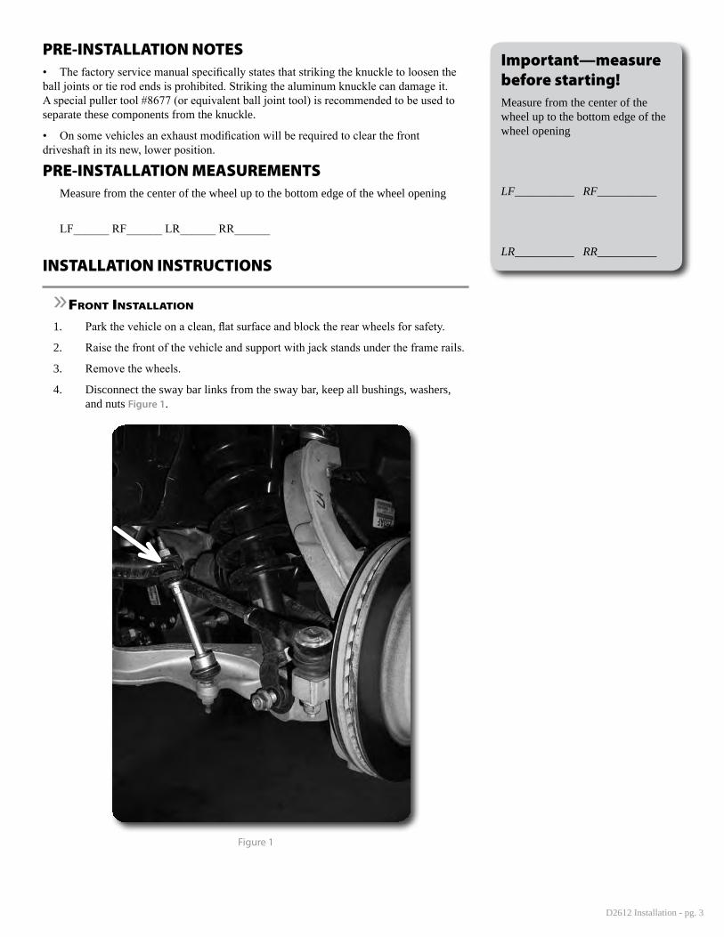
4. Disconnect the sway bar links from the sway bar, keep all bushings, washers, and nuts Figure 1.
Figure 1
Important—measure before starting!Measure from the center of the wheel up to the bottom edge of the wheel opening
LF__________ RF__________
LR__________ RR__________
D2612 Installation - pg. 4
5. Remove and discard the factory front skid plate, if equipped.
6. Disconnect the tie rod ends from the steering knuckles. Remove and retain the mounting nuts. Use the appropriate puller to separate the tie rod end from the steering knuckle. Take care not to damage the tie rod end.
7. Disconnect the ABS brake line at the frame. Remove it from any retaining clips.
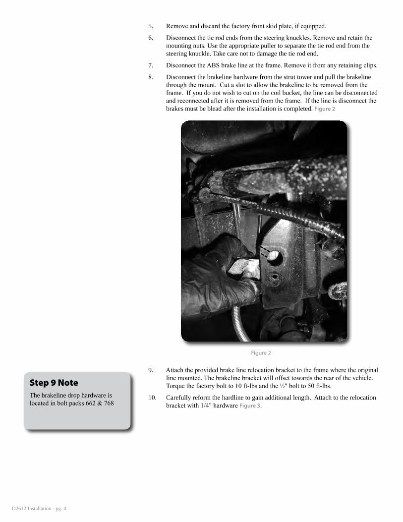
8. Disconnect the brakeline hardware from the strut tower and pull the brakeline through the mount. Cut a slot to allow the brakeline to be removed from the frame. If you do not wish to cut on the coil bucket, the line can be disconnected and reconnected after it is removed from the frame. If the line is disconnect the brakes must be blead after the installation is completed. Figure 2
Figure 2
9. Attach the provided brake line relocation bracket to the frame where the original line mounted. The brakeline bracket will offset towards the rear of the vehicle. Torque the factory bolt to 10 ft-lbs and the ½" bolt to 50 ft-lbs.
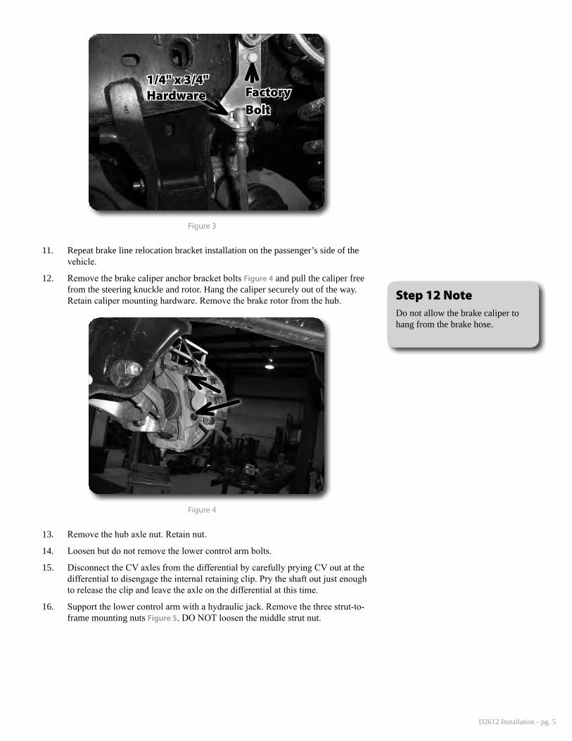
10. Carefully reform the hardline to gain additional length. Attach to the relocation bracket with 1/4" hardware Figure 3.
Step 9 NoteThe brakeline drop hardware is located in bolt packs 662 & 768
D2612 Installation - pg. 5
1/4" x 3/4" Hardware Factory
Bolt
Figure 3
11. Repeat brake line relocation bracket installation on the passenger’s side of the vehicle.
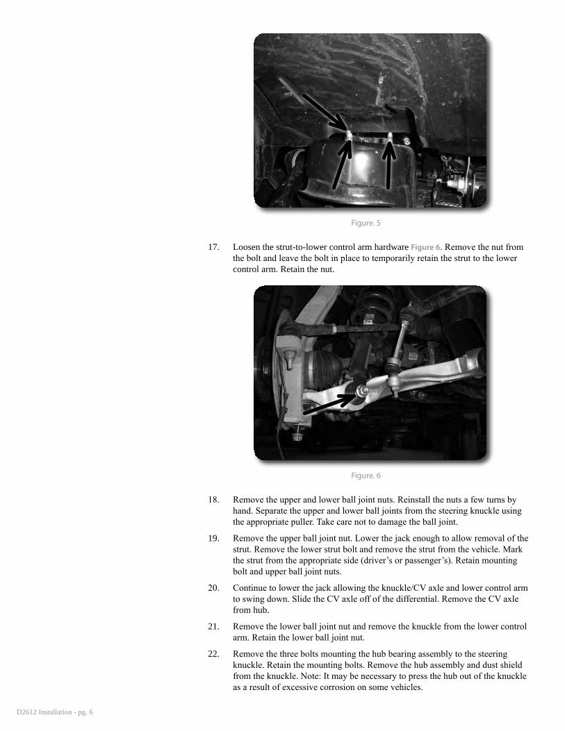
12. Remove the brake caliper anchor bracket bolts Figure 4 and pull the caliper free from the steering knuckle and rotor. Hang the caliper securely out of the way. Retain caliper mounting hardware. Remove the brake rotor from the hub.
Figure 4
13. Remove the hub axle nut. Retain nut.
14. Loosen but do not remove the lower control arm bolts.
15. Disconnect the CV axles from the differential by carefully prying CV out at the differential to disengage the internal retaining clip. Pry the shaft out just enough to release the clip and leave the axle on the differential at this time.
16. Support the lower control arm with a hydraulic jack. Remove the three strut-to-frame mounting nuts Figure 5. DO NOT loosen the middle strut nut.
Step 12 NoteDo not allow the brake caliper to hang from the brake hose.
D2612 Installation - pg. 6
Figure. 5
17. Loosen the strut-to-lower control arm hardware Figure 6. Remove the nut from the bolt and leave the bolt in place to temporarily retain the strut to the lower control arm. Retain the nut.
Figure. 6
18. Remove the upper and lower ball joint nuts. Reinstall the nuts a few turns by hand. Separate the upper and lower ball joints from the steering knuckle using the appropriate puller. Take care not to damage the ball joint.
19. Remove the upper ball joint nut. Lower the jack enough to allow removal of the strut. Remove the lower strut bolt and remove the strut from the vehicle. Mark the strut from the appropriate side (driver’s or passenger’s). Retain mounting bolt and upper ball joint nuts.
20. Continue to lower the jack allowing the knuckle/CV axle and lower control arm to swing down. Slide the CV axle off of the differential. Remove the CV axle from hub.
21. Remove the lower ball joint nut and remove the knuckle from the lower control arm. Retain the lower ball joint nut.
22. Remove the three bolts mounting the hub bearing assembly to the steering knuckle. Retain the mounting bolts. Remove the hub assembly and dust shield from the knuckle. Note: It may be necessary to press the hub out of the knuckle as a result of excessive corrosion on some vehicles.
D2612 Installation - pg. 7
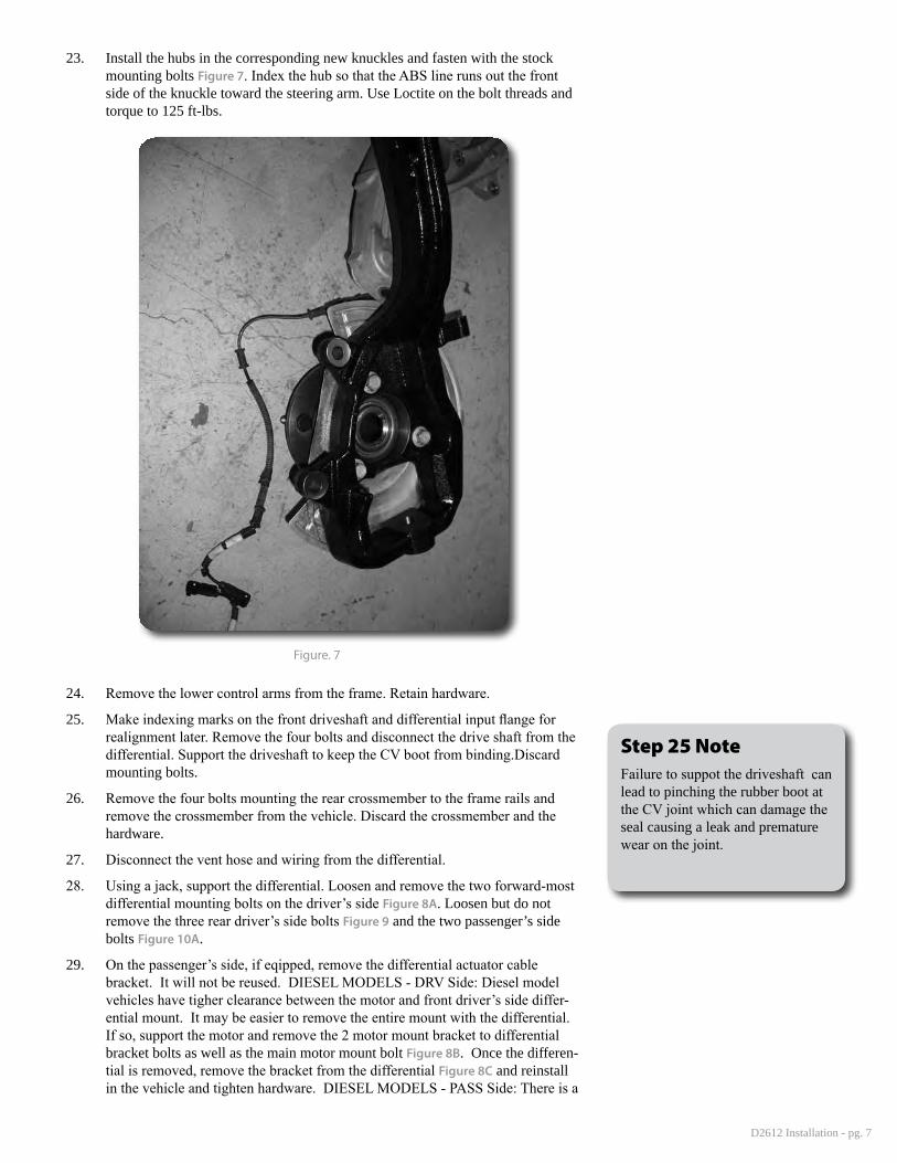
23. Install the hubs in the corresponding new knuckles and fasten with the stock mounting bolts Figure 7. Index the hub so that the ABS line runs out the front side of the knuckle toward the steering arm. Use Loctite on the bolt threads and torque to 125 ft-lbs.
Figure. 7
24. Remove the lower control arms from the frame. Retain hardware.
25. Make indexing marks on the front driveshaft and differential input flange for realignment later. Remove the four bolts and disconnect the drive shaft from the differential. Support the driveshaft to keep the CV boot from binding.Discard mounting bolts.
26. Remove the four bolts mounting the rear crossmember to the frame rails and remove the crossmember from the vehicle. Discard the crossmember and the hardware.
27. Disconnect the vent hose and wiring from the differential.
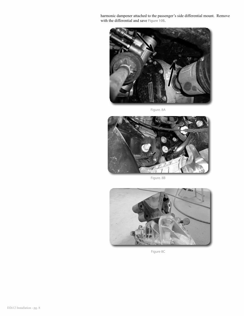
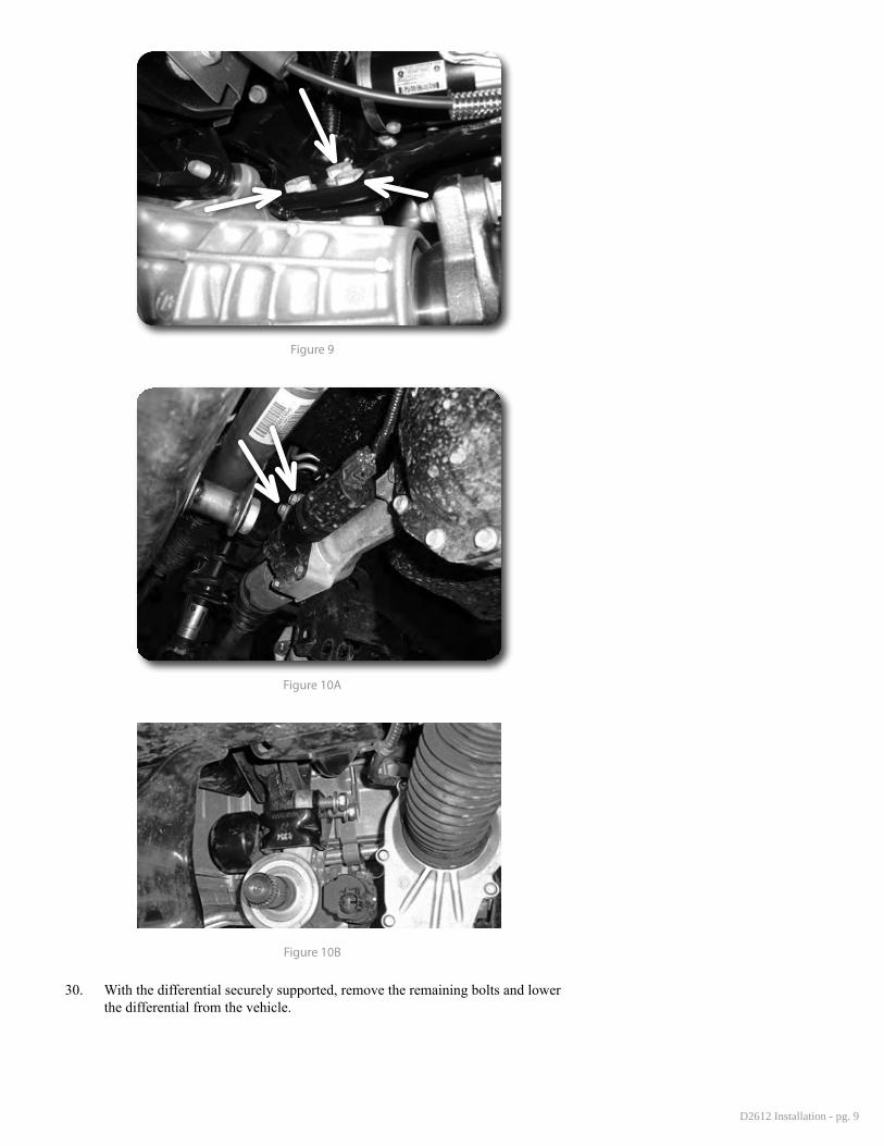
28. Using a jack, support the differential. Loosen and remove the two forward-most differential mounting bolts on the driver’s side Figure 8A. Loosen but do not remove the three rear driver’s side bolts Figure 9 and the two passenger’s side bolts Figure 10A.
29. On the passenger’s side, if eqipped, remove the differential actuator cable bracket. It will not be reused. DIESEL MODELS - DRV Side: Diesel model vehicles have tigher clearance between the motor and front driver’s side differ-ential mount. It may be easier to remove the entire mount with the differential. If so, support the motor and remove the 2 motor mount bracket to differential bracket bolts as well as the main motor mount bolt Figure 8B. Once the differen-tial is removed, remove the bracket from the differential Figure 8C and reinstall in the vehicle and tighten hardware. DIESEL MODELS - PASS Side: There is a
Step 25 NoteFailure to suppot the driveshaft can lead to pinching the rubber boot at the CV joint which can damage the seal causing a leak and premature wear on the joint.
D2612 Installation - pg. 8
harmonic dampener attached to the passenger’s side differential mount. Remove with the differential and save Figure 10B.
Figure. 8A
Figure. 8B
Figure 8C
D2612 Installation - pg. 9
Figure 9
Figure 10A
Figure 10B
30. With the differential securely supported, remove the remaining bolts and lower the differential from the vehicle.
D2612 Installation - pg. 10
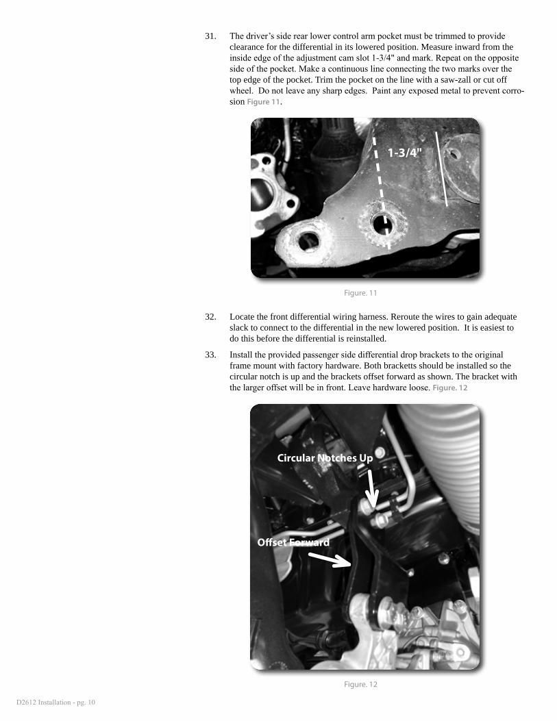
31. The driver’s side rear lower control arm pocket must be trimmed to provide clearance for the differential in its lowered position. Measure inward from the inside edge of the adjustment cam slot 1-3/4" and mark. Repeat on the opposite side of the pocket. Make a continuous line connecting the two marks over the top edge of the pocket. Trim the pocket on the line with a saw-zall or cut off wheel. Do not leave any sharp edges. Paint any exposed metal to prevent corro-sion Figure 11.
1-3/4"
Figure. 11
32. Locate the front differential wiring harness. Reroute the wires to gain adequate slack to connect to the differential in the new lowered position. It is easiest to do this before the differential is reinstalled.
33. Install the provided passenger side differential drop brackets to the original frame mount with factory hardware. Both bracketts should be installed so the circular notch is up and the brackets offset forward as shown. The bracket with the larger offset will be in front. Leave hardware loose. Figure. 12
Circular Notches Up
Offset Forward
Figure. 12
D2612 Installation - pg. 11
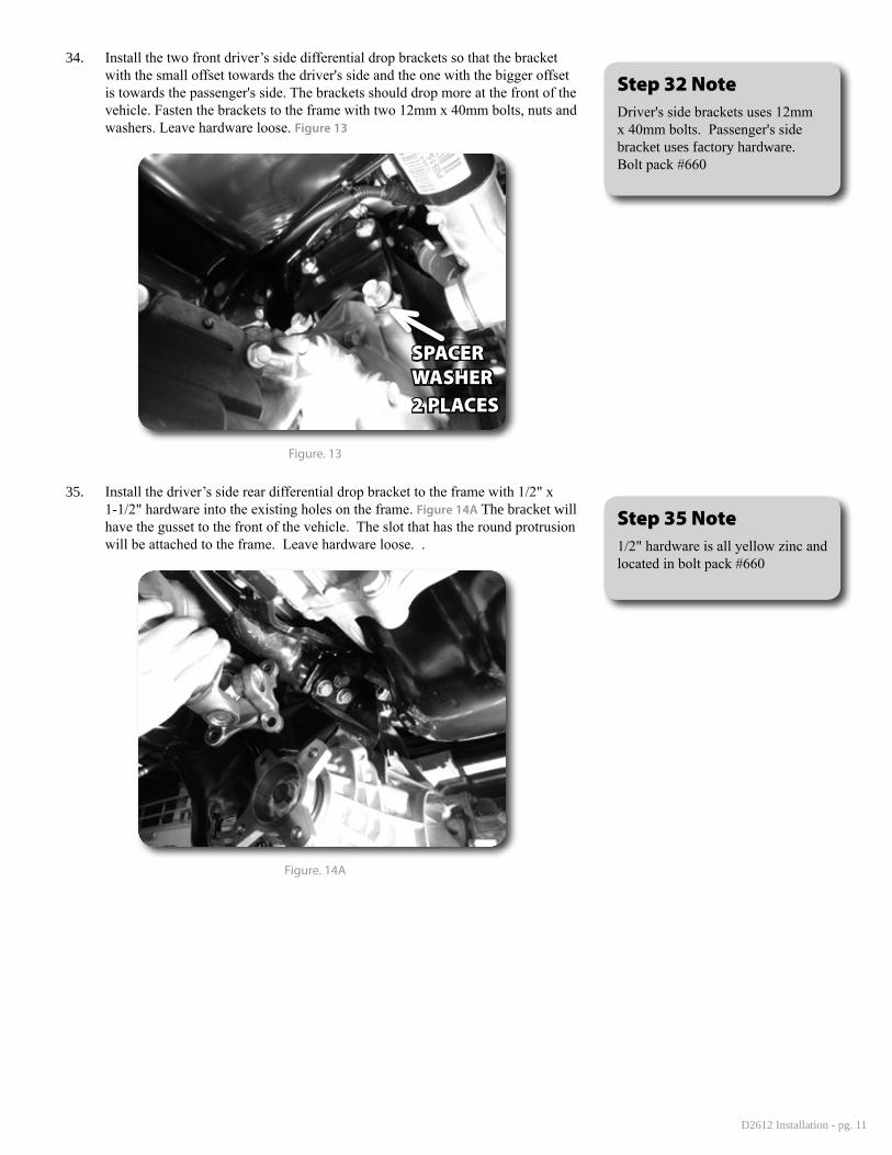
34. Install the two front driver’s side differential drop brackets so that the bracket with the small offset towards the driver's side and the one with the bigger offset is towards the passenger's side. The brackets should drop more at the front of the vehicle. Fasten the brackets to the frame with two 12mm x 40mm bolts, nuts and washers. Leave hardware loose. Figure 13
SPACER WASHER2 PLACES
Figure. 13
35. Install the driver’s side rear differential drop bracket to the frame with 1/2" x 1-1/2" hardware into the existing holes on the frame. Figure 14A The bracket will have the gusset to the front of the vehicle. The slot that has the round protrusion will be attached to the frame. Leave hardware loose. .
Figure. 14A
Step 32 NoteDriver's side brackets uses 12mm x 40mm bolts. Passenger's side bracket uses factory hardware. Bolt pack #660
Step 35 Note1/2" hardware is all yellow zinc and located in bolt pack #660
D2612 Installation - pg. 12
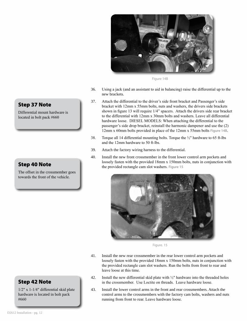
Figure 14B
36. Using a jack (and an assistant to aid in balancing) raise the differential up to the new brackets.
37. Attach the differential to the driver’s side front bracket and Passenger’s side bracket with 12mm x 55mm bolts, nuts and washers, the drivers side brackets shown in figure 13 will require 1/4” spacers. Attach the drivers side rear bracket to the differential with 12mm x 30mm bolts and washers. Leave all differential hardware loose. DIESEL MODELS: When attaching the differential to the passenger’s side drop bracket, reinstall the harmonic dampener and use the (2) 12mm x 60mm bolts provided in place of the 12mm x 55mm bolts Figure 14B.
38. Torque all 14 differential mounting bolts. Torque the ½" hardware to 65 ft-lbs and the 12mm hardware to 50 ft-lbs.
39. Attach the factory wiring harness to the differential.
40. Install the new front crossmember in the front lower control arm pockets and loosely fasten with the provided 18mm x 150mm bolts, nuts in conjunction with the provided rectangle cam slot washers. Figure 15
Figure. 15
41. Install the new rear crossmember in the rear lower control arm pockets and loosely fasten with the provided 18mm x 150mm bolts, nuts in conjunction with the provided rectangle cam slot washers. Run the bolts from front to rear and leave loose at this time.
42. Install the new differential skid plate with ½" hardware into the threaded holes in the crossmember. Use Loctite on threads. Leave hardware loose.
43. Install the lower control arms in the front and rear crossmembers. Attach the control arms to the crossmembers with the factory cam bolts, washers and nuts running from front to rear. Leave hardware loose.
Step 40 NoteThe offset in the crossmember goes towards the front of the vehicle.
Step 42 Note1/2" x 1-1/4" differential skid plate hardware is located in bolt pack #660
Step 37 NoteDifferential mount hardware is located in bolt pack #660
D2612 Installation - pg. 13
44. With the lower control arms installed, torque the 18mm crossmember mounting bolts to 220 ft-lbs. Torque the ½" differential skid plate hardware to 65 ft-lbs.
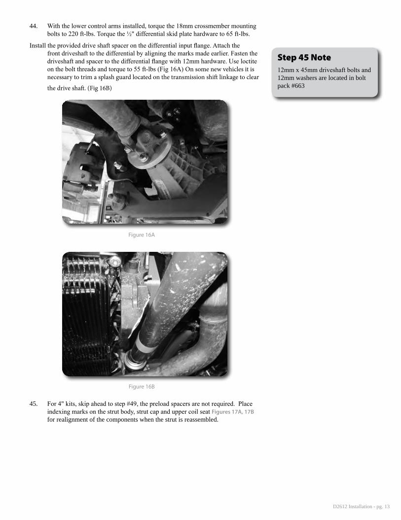
Install the provided drive shaft spacer on the differential input flange. Attach the front driveshaft to the differential by aligning the marks made earlier. Fasten the driveshaft and spacer to the differential flange with 12mm hardware. Use loctite on the bolt threads and torque to 55 ft-lbs (Fig 16A) On some new vehicles it is necessary to trim a splash guard located on the transmission shift linkage to clear
the drive shaft. (Fig 16B)
Figure 16A
Figure 16B
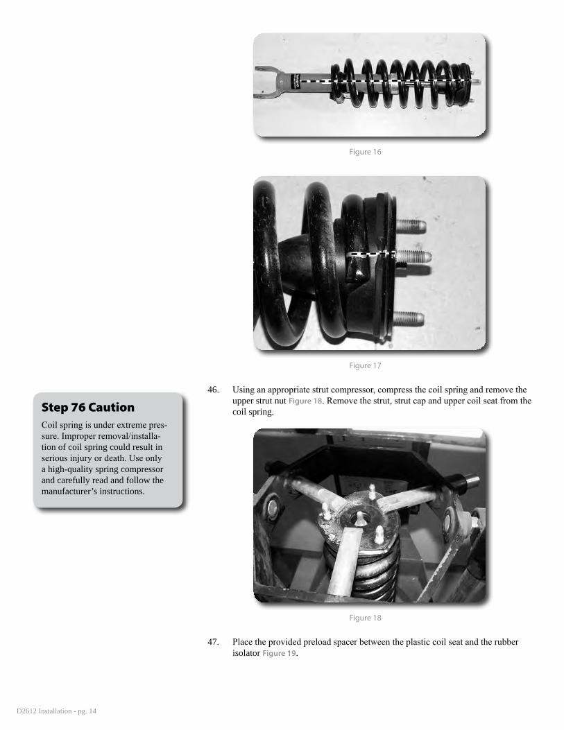
45. For 4" kits, skip ahead to step #49, the preload spacers are not required. Place indexing marks on the strut body, strut cap and upper coil seat Figures 17A, 17B for realignment of the components when the strut is reassembled.
Step 45 Note12mm x 45mm driveshaft bolts and 12mm washers are located in bolt pack #663
D2612 Installation - pg. 14
Figure 16
Figure 17
46. Using an appropriate strut compressor, compress the coil spring and remove the upper strut nut Figure 18. Remove the strut, strut cap and upper coil seat from the coil spring.
Figure 18
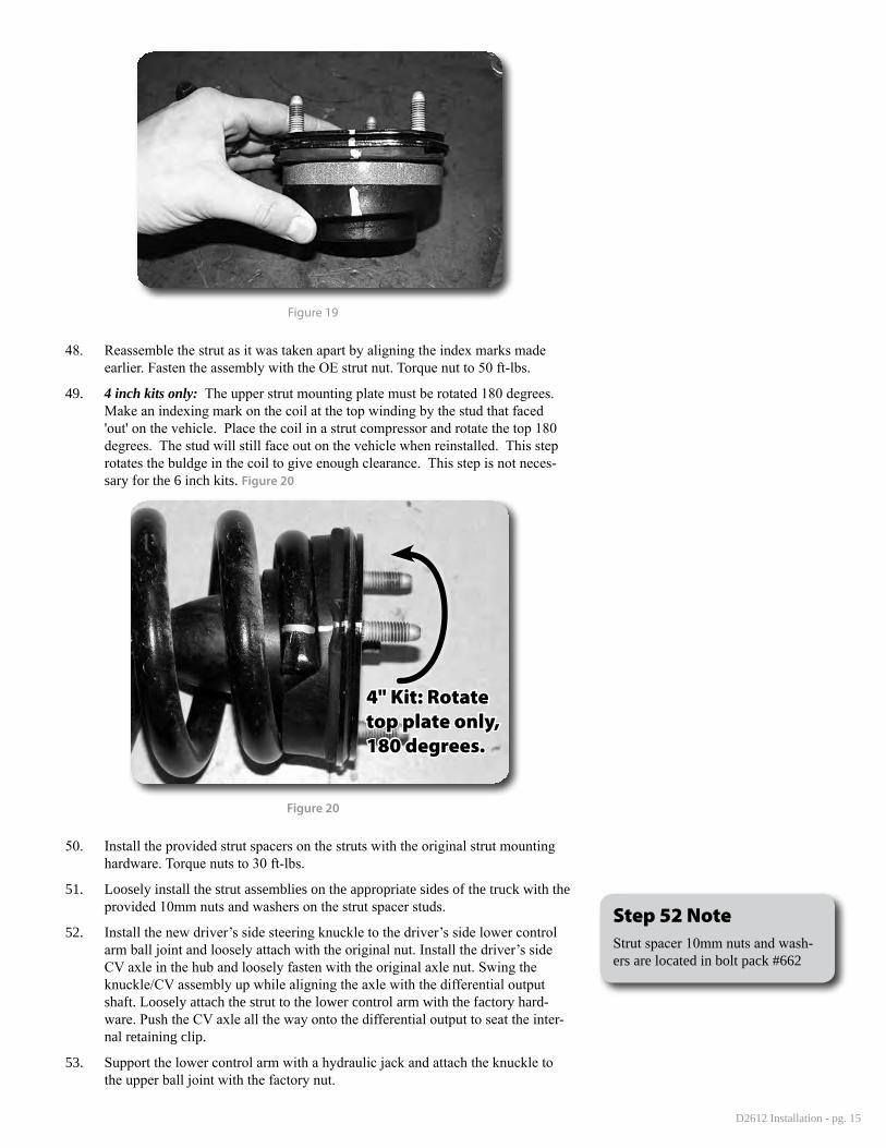
47. Place the provided preload spacer between the plastic coil seat and the rubber isolator Figure 19.
Step 76 CautionCoil spring is under extreme pres-sure. Improper removal/installa-tion of coil spring could result in serious injury or death. Use only a high-quality spring compressor and carefully read and follow the manufacturer’s instructions.
D2612 Installation - pg. 15
Figure 19
48. Reassemble the strut as it was taken apart by aligning the index marks made earlier. Fasten the assembly with the OE strut nut. Torque nut to 50 ft-lbs.
49. 4 inch kits only: The upper strut mounting plate must be rotated 180 degrees. Make an indexing mark on the coil at the top winding by the stud that faced 'out' on the vehicle. Place the coil in a strut compressor and rotate the top 180 degrees. The stud will still face out on the vehicle when reinstalled. This step rotates the buldge in the coil to give enough clearance. This step is not neces-sary for the 6 inch kits. Figure 20
4" Kit: Rotate top plate only, 180 degrees.
Figure 20
50. Install the provided strut spacers on the struts with the original strut mounting hardware. Torque nuts to 30 ft-lbs.
51. Loosely install the strut assemblies on the appropriate sides of the truck with the provided 10mm nuts and washers on the strut spacer studs.
52. Install the new driver’s side steering knuckle to the driver’s side lower control arm ball joint and loosely attach with the original nut. Install the driver’s side CV axle in the hub and loosely fasten with the original axle nut. Swing the knuckle/CV assembly up while aligning the axle with the differential output shaft. Loosely attach the strut to the lower control arm with the factory hard-ware. Push the CV axle all the way onto the differential output to seat the inter-nal retaining clip.
53. Support the lower control arm with a hydraulic jack and attach the knuckle to the upper ball joint with the factory nut.
Step 52 NoteStrut spacer 10mm nuts and wash-ers are located in bolt pack #662
D2612 Installation - pg. 16
54. Torque the upper ball joint nut to 55 ft-lbs and the lower ball joint nut to 60 ft-lbs. Torque the axle nut to 185 ft-lbs. Torque the upper strut-to-frame nuts to 30 ft-lbs.
55. Repeat knuckle/CV installation on passenger’s side.
56. Install the brake rotor and caliper on the knuckle/hub. Torque the caliper bolts to 130 ft-lbs. Use loctite on the caliper bolts.
57. Remove the factory tie rod ends. Trim 5/8" from the end of the male thread on the tie rod end. Clean up the cut edge with a flap wheel.
58. Install new tie rod ends to the new steering knuckles with OE nut. Torque to 55 ft-lbs. To seat the tie rod end, it may be necessary to pry down on the tie rod with a pry bar while tightening the nut. Secure off the jam nut.
59. Connect the ABS wire at the frame.
60. Route the brake and ABS lines around the back side of the knuckle and use zip ties to secure them out of the way of any moving or rotating parts. Make sure the lines cannot get pinched between the knuckle and the coil spring.
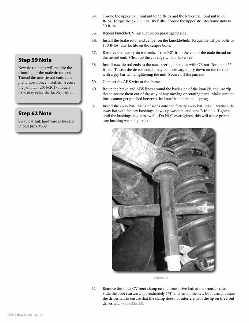
61. Install the sway bar link extensions onto the factory sway bar links. Reattach the sway bar with factory bushings, new cup washers, and new 7/16 nuts. Tighten until the bushings begin to swell - Do NOT overtighten, this will cause prema-ture bushing wear. Figure 21
Figure 21
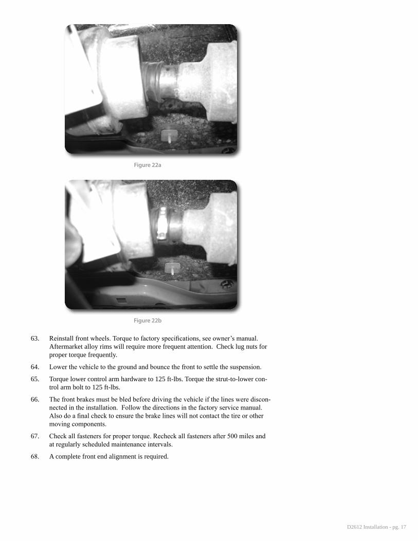
62. Remove the stock CV boot clamp on the front driveshaft at the transfer case. Slide the boot rearward approximately 1/4” and install the new boot clamp, rotate the driveshaft to ensure that the clamp does not interfere with the lip on the front driveshaft. Figure 22a, 22b
Step 59 NoteNew tie rod ends will require the trimming of the male tie rod end. Thread the new tie rod ends com-pletly down once installed. Secure the jam nut. 2016-2017 models have may reuse the facotry jam nut
Step 62 NoteSway bar link hardware is located in bolt pack #662
D2612 Installation - pg. 17
Figure 22a
Figure 22b
63. Reinstall front wheels. Torque to factory specifications, see owner’s manual. Aftermarket alloy rims will require more frequent attention. Check lug nuts for proper torque frequently.
64. Lower the vehicle to the ground and bounce the front to settle the suspension.
65. Torque lower control arm hardware to 125 ft-lbs. Torque the strut-to-lower con-trol arm bolt to 125 ft-lbs.
66. The front brakes must be bled before driving the vehicle if the lines were discon-nected in the installation. Follow the directions in the factory service manual. Also do a final check to ensure the brake lines will not contact the tire or other moving components.
67. Check all fasteners for proper torque. Recheck all fasteners after 500 miles and at regularly scheduled maintenance intervals.
68. A complete front end alignment is required.
D2612 Installation - pg. 18
»rear inStallation
69. Park the vehicle on clean, flat, and level surface. Block the front wheels for safety. Disconnect the rear trackbar from the axle before lifting the vehicle. Retain bolt and nut tab.
70. Raise the rear of the vehicle and support the frame rails with jackstands.
71. Remove the wheels.
72. Support the axle with a hydraulic jack.
73. Remove the factory shocks. Retain the mounting hardware. It is easiest to remove the upper hardware by using a long extension and a deep chrome (thin walled) 7/8"or 22mm 6 point socket. Even though the nut takes a 21mm socket, it is extremely difficult to fit it into position. We have reduced our installation time using this method. The upper hardware is replaced later in the installation with a new bolt and nut tab.
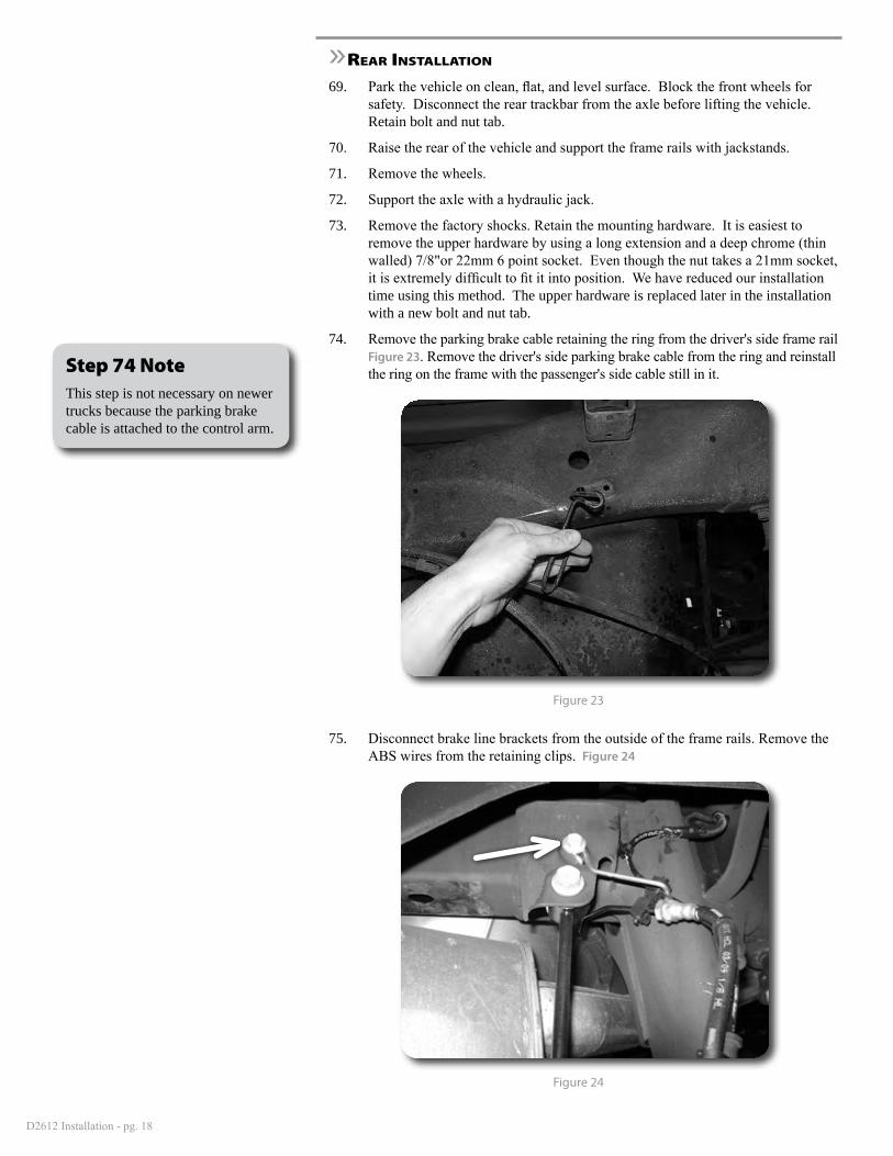
74. Remove the parking brake cable retaining the ring from the driver's side frame rail Figure 23. Remove the driver's side parking brake cable from the ring and reinstall the ring on the frame with the passenger's side cable still in it.
Figure 23
75. Disconnect brake line brackets from the outside of the frame rails. Remove the ABS wires from the retaining clips. Figure 24
Figure 24
Step 74 NoteThis step is not necessary on newer trucks because the parking brake cable is attached to the control arm.
D2612 Installation - pg. 19
76. Remove rear sway bar links, retain hardware.
77. Lower the rear axle and remove the coils, retain the rubber isolators.
78. Disconnect the upper control arm from the axle. Loosen the upper control arm bolt at the frame rail, but do not remove. Retain hardware.
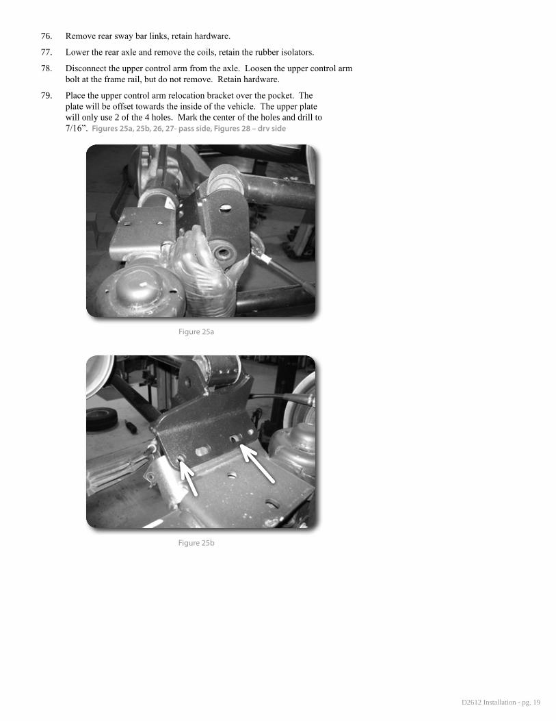
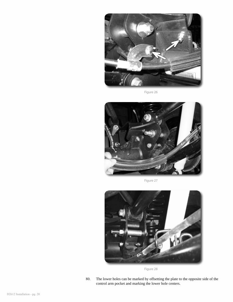
79. Place the upper control arm relocation bracket over the pocket. The plate will be offset towards the inside of the vehicle. The upper plate will only use 2 of the 4 holes. Mark the center of the holes and drill to 7/16”. Figures 25a, 25b, 26, 27- pass side, Figures 28 – drv side
Figure 25a
Figure 25b
D2612 Installation - pg. 20
Figure 26
Figure 27
Figure 28
80. The lower holes can be marked by offsetting the plate to the opposite side of the control arm pocket and marking the lower hole centers.
D2612 Installation - pg. 21
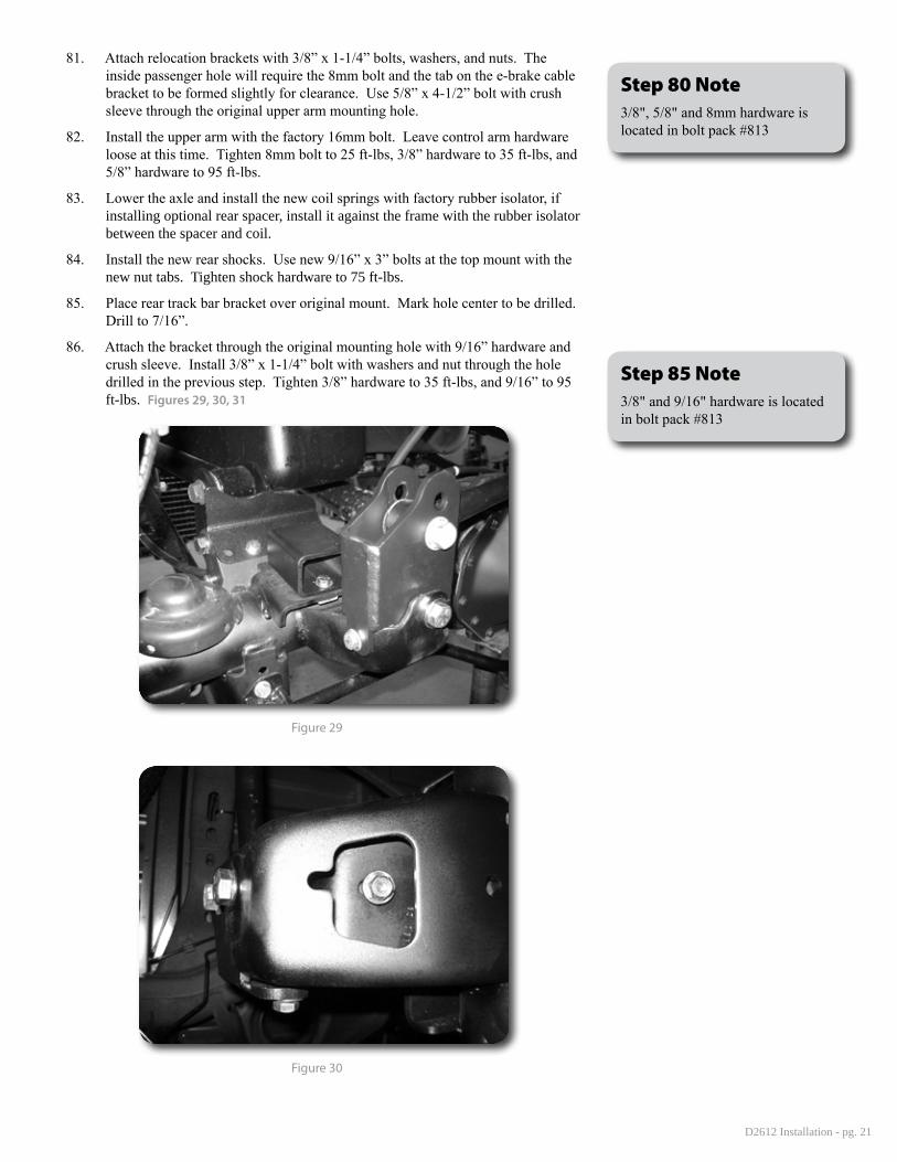
81. Attach relocation brackets with 3/8” x 1-1/4” bolts, washers, and nuts. The inside passenger hole will require the 8mm bolt and the tab on the e-brake cable bracket to be formed slightly for clearance. Use 5/8” x 4-1/2” bolt with crush sleeve through the original upper arm mounting hole.
82. Install the upper arm with the factory 16mm bolt. Leave control arm hardware loose at this time. Tighten 8mm bolt to 25 ft-lbs, 3/8” hardware to 35 ft-lbs, and 5/8” hardware to 95 ft-lbs.
83. Lower the axle and install the new coil springs with factory rubber isolator, if installing optional rear spacer, install it against the frame with the rubber isolator between the spacer and coil.
84. Install the new rear shocks. Use new 9/16” x 3” bolts at the top mount with the new nut tabs. Tighten shock hardware to 75 ft-lbs.
85. Place rear track bar bracket over original mount. Mark hole center to be drilled. Drill to 7/16”.
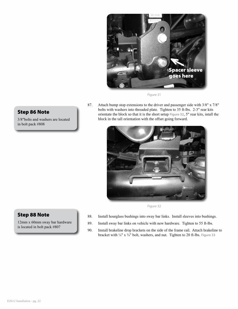
86. Attach the bracket through the original mounting hole with 9/16” hardware and crush sleeve. Install 3/8” x 1-1/4” bolt with washers and nut through the hole drilled in the previous step. Tighten 3/8” hardware to 35 ft-lbs, and 9/16” to 95 ft-lbs. Figures 29, 30, 31
Figure 29
Figure 30
Step 80 Note3/8", 5/8" and 8mm hardware is located in bolt pack #813
Step 85 Note3/8" and 9/16" hardware is located in bolt pack #813
D2612 Installation - pg. 22
Spacer sleevegoes here
Figure 31
87. Attach bump stop extensions to the driver and passenger side with 3/8" x 7/8" bolts with washers into threaded plate. Tighten to 35 ft-lbs. 2-3" rear kits orientate the block so that it is the short setup Figure 32, 5" rear kits, intall the block in the tall orientation with the offset going forward.
Figure 32
88. Install hourglass bushings into sway bar links. Install sleeves into bushings.
89. Install sway bar links on vehicle with new hardware. Tighten to 55 ft-lbs.
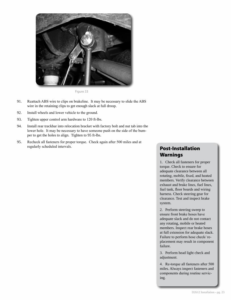
90. Install brakeline drop brackets on the side of the frame rail. Attach brakeline to bracket with ¼" x ¾" bolt, washers, and nut. Tighten to 20 ft-lbs. Figure 33
Step 86 Note3/8"bolts and washers are located in bolt pack #808
Step 88 Note12mm x 60mm sway bar hardware is located in bolt pack #807
D2612 Installation - pg. 23
Figure 33
91. Reattach ABS wire to clips on brakeline. It may be necessary to slide the ABS wire in the retaining clips to get enough slack at full droop.
92. Install wheels and lower vehicle to the ground.
93. Tighten upper control arm hardware to 120 ft-lbs.
94. Install rear trackbar into relocation bracket with factory bolt and nut tab into the lower hole. It may be necessary to have someone push on the side of the bum-per to get the holes to align. Tighten to 95 ft-lbs.
95. Recheck all fasteners for proper torque. Check again after 500 miles and at regularly scheduled intervals. Post-Installation
Warnings1. Check all fasteners for proper torque. Check to ensure for adequate clearance between all rotating, mobile, fixed, and heated members. Verify clearance between exhaust and brake lines, fuel lines, fuel tank, floor boards and wiring harness. Check steering gear for clearance. Test and inspect brake system.
2. Perform steering sweep to ensure front brake hoses have adequate slack and do not contact any rotating, mobile or heated members. Inspect rear brake hoses at full extension for adequate slack. Failure to perform hose check/ re-placement may result in component failure.
3. Perform head light check and adjustment.
4. Re-torque all fasteners after 500 miles. Always inspect fasteners and components during routine servic-ing.