Page 1
This project has received funding from the European Union’s Horizon 2020 research
and innovation programme under grant agreement No 723172, and from the Swiss
State Secretariat for Education, Research and Innovation.
D3.1 – Slice Components Design – ver. 1.0
UT, FOKUS, AALTO, Ericsson, Orange, WU, EURECOM, MI, NESIC
Document Number D3.1
Status Final Version v1.0
Work Package WP 3
Deliverable Type Report
Date of Delivery 5/August/2017
Responsible UT
Contributors FOKUS, AALTO, Ericsson, Orange, Waseda U,
EURECOM, MI, NESIC
Dissemination level PU
This document has been produced by the 5GPagoda project, funded by the Horizon 2020 Programme of the
European Community. The content presented in this document represents the views of the authors, and the
European Commission has no liability in respect of the content.
Page 2
D3.1 – Slice Components Design
5G!Pagoda Version 1.0.0 Page 2 of 103
AUTHORS
Full Name Affiliation
Akihiro Nakao University of Tokyo
Du Ping University of Tokyo
Shu Yamamoto University of Tokyo
Yoshiaki Kiriha University of Tokyo
Marius-Iulian Corici Fraunhofer FOKUS
Eleonora Cau Fraunhofer FOKUS
Fabian Eichhorn Fraunhofer FOKUS
Tarik Taleb Aalto University
Miloud Bagaa Aalto University
Ibrahim Afolabi Aalto University
Laghrissi Abdelquoddouss Aalto University
Nicklas Beijar ERICSSON
Sławomir Kukliński Orange
Tomasz Osiński Orange
Lechosław Tomaszewski Orange
Toshitaka Tsuda Waseda University
Takuro Sato Waseda University
Quang Nguyen Waseda University
Adlen Ksentini EURECOM
Sebastien Ziegler Mandat International
Kauto Satou NESIC
Masato Yamazaki NESIC
Hiroshi Takezawa NESIC
Page 3
D3.1 – Slice Components Design
5G!Pagoda Version 1.0.0 Page 3 of 103
Executive Summary
This deliverable provides the basis for the work of WP3 of the 5G!Pagoda project, which aims to define
foundation (Control Plane, Data Plane, APIs) for building customized connectivity in different virtual
network functions and components, to develop functionality which enables to control connectivity, data-
path delivery, and adaption to network function placement within a slice, to design and implementation of
a set of mechanisms which ensure the flexibility, elasticity, and reliability of the virtual control plane, and
to design and implementation of specific subscriber state information placement algorithms for the
emerging customized services.
The document begins with a comprehensive overview of the 5G!Pagoda architecture which described in
D2.1~D2.3. Subsequently, as unique and novel technologies, the lightweight control plane, the data plane
programmability and slice composition algorithms and mechanisms, are described in more detail. In section
4 (Lightweight Control Plane), a mechanism for creating customized core networks based on the definition
of a minimal lightweight core network and its further composition using micro-services is presented. In
section 5 (Data Plane Programmability), we describe a deeply programmable data plane architecture which
enables to realize an application centric end-to-end network slicing, in order to deal with various
requirements such as differentiate QoS, ultra-low latency, highly reliability, customizable security, and
massive scalability. In section 6 (Slice Composition Algorithms and Mechanisms), we present a network
slice planner, which is considered as a novel and efficient tool for both spatiotemporal simulation of mobile
service usage and a solid ground for testing algorithms, strategies and policies. Those aim to create optimal
network slices, and support different 5G verticals. Moreover, novel placement schemes for edge and core
VNF placement, mobility management, network slicing and load balancing which have proven their
efficiency as key techniques of the upcoming 5G, are discussed in more detail.
The outcomes of this document will guide the future work in 5G!Pagoda as follows:
More detailed investigation on WP3
Interaction with WP4
Implementation and validation with WP5
In fact, described frameworks and mechanisms will be integrated and deployed as 5G!Pagoda EU/Japan
coordinated testbed systems, then various validation activities will be carried out as tasks in WP5:
Integrated Testbed & Validation.
Page 4
D3.1 – Slice Components Design
5G!Pagoda Version 1.0.0 Page 4 of 103
Table of Contents
1. Introduction ....................................................................................................................... 12
1.1. Objectives .....................................................................................................................................12
1.2. Motivation and Scope ..................................................................................................................12
1.3. Relationships with other WPs ......................................................................................................13
1.4. Structure of the document...........................................................................................................13
2. Terminology ....................................................................................................................... 14
3. 5G!Pagoda Architecture ...................................................................................................... 17
3.1. Slice Architecture [defined in D2.1] .............................................................................................17
3.2. Multi-domain Orchestration Architecture [defined in D2.1] .......................................................19
3.3. Reference Architecture [defined in D2.3] ....................................................................................20
3.4. Emerging Role of MVNO ..............................................................................................................21
3.5. 5G!Pagoda Original and Unique Contributions ............................................................................22
4. Lightweight Control Plane ................................................................................................... 23
4.1. Problem Statement ......................................................................................................................24
4.1.1. Motivation ...........................................................................................................................24
4.1.2. Goals ....................................................................................................................................24
4.1.3. Key Supporting Technologies ...............................................................................................25
4.2. Core Network Decomposition ......................................................................................................28
4.2.1. Definition of micro-functions ...............................................................................................28
4.2.2. Security micro-functions ......................................................................................................30
4.2.3. Access Control ......................................................................................................................31
4.2.4. Mobility ................................................................................................................................32
4.2.5. Session Micro-Functions ......................................................................................................33
4.3. Mechanisms for Binding Micro-Functions ...................................................................................35
4.3.1. Interconnection and Routing Function ................................................................................35
4.3.2. Repository Function .............................................................................................................36
4.3.3. Dedicated protocols .............................................................................................................37
4.3.4. Shared Libraries ...................................................................................................................37
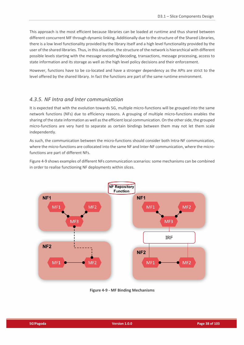
4.3.5. NF Intra and Inter communication ......................................................................................38
4.4. Interaction with the Data Plane ...................................................................................................40
4.5. Slice View Architecture ................................................................................................................40
4.6. Fraunhofer FOKUS Open5GCore Implementation .......................................................................42
Page 5
D3.1 – Slice Components Design
5G!Pagoda Version 1.0.0 Page 5 of 103
5. Data Plane Programmability ............................................................................................... 44
5.1. Requirements and Related Works ...............................................................................................44
5.1.1. Background ..........................................................................................................................44
5.1.2. Gap Analysis towards Application Centric E2E Network Slicing ..........................................45
5.1.3. Related Research Works ......................................................................................................46
5.1.4. Use Case Applications thanks to Data Plane Programmability ............................................47
5.2. Basic Programmable Data Plane Architecture .............................................................................48
5.2.1. Deeply Programmable Data Plane Architecture ..................................................................50
5.2.2. Related Work on Data Plane Programmability ....................................................................51
5.2.3. Deeply Programmable Node ................................................................................................53
5.2.4. Trailer Slicing ........................................................................................................................54
5.2.5. MEC Slicing ...........................................................................................................................55
5.2.6. Use Cases for Data Plane Programmability .........................................................................55
5.3. FLARE based Data Plane Framework............................................................................................59
5.3.1. Hardware Framework ..........................................................................................................59
5.3.2. Software Framework ...........................................................................................................60
5.3.3. eNB Slicing ...........................................................................................................................61
5.3.4. EPC Slicing ............................................................................................................................61
5.3.5. Prototype System Integration ..............................................................................................63
5.4. Control Plane Interactions ...........................................................................................................66
5.4.1. Requirements and Programmable Data Plane Improvements ............................................66
5.4.2. Control Plane Interaction Architecture ................................................................................66
5.4.3. Control Plane Interaction Design and Future Issues ............................................................68
5.5. ICN related Functions ...................................................................................................................70
5.5.1. NDN Basic Functions ............................................................................................................70
5.5.2. Additional Functions ............................................................................................................72
6. Slice Composition Algorithms & Mechanisms ~Network Slice Planning Framework~ ............ 73
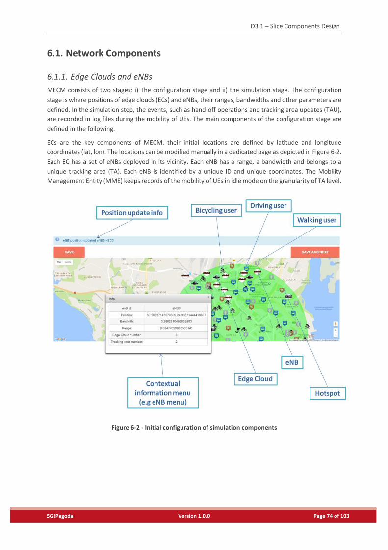
6.1. Network Components ..................................................................................................................74
6.1.1. Edge Clouds and eNBs .........................................................................................................74
6.1.2. Tracking Area and Tracking Area Updates ...........................................................................75
6.1.3. VNFs and VMs Flavours .......................................................................................................75
6.2. Mobility Management and Service Usage ...................................................................................76
6.2.1. UE Mobility ..........................................................................................................................76
Page 6
D3.1 – Slice Components Design
5G!Pagoda Version 1.0.0 Page 6 of 103
6.2.2. Mobility Management .........................................................................................................76
6.2.3. Service Usage .......................................................................................................................88
6.3. Inputs and Outputs ......................................................................................................................89
6.3.1. Settings and Parameters ......................................................................................................89
6.3.2. Logs ......................................................................................................................................89
6.4. Network Function Placement Strategies......................................................................................90
6.4.1. Least Used Host ...................................................................................................................90
6.4.2. Predictive Placement ...........................................................................................................90
6.4.3. Advanced Predictive Placement ..........................................................................................90
6.4.4. Edge and core VNF Placement .............................................................................................91
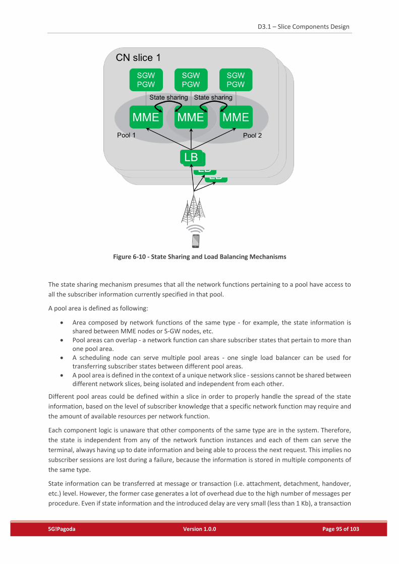
6.4.5. Dynamic State Sharing and Load Balancing Mechanisms ....................................................94
6.4.6. Optimal Slices driven VNF Placement ..................................................................................97
7. Concluding Remarks ........................................................................................................... 99
Page 7
D3.1 – Slice Components Design
5G!Pagoda Version 1.0.0 Page 7 of 103
List of Tables
Table 1 - List of Acronyms .....................................................................................................................10
Table 2 - Terms defined in this document. ...........................................................................................14
Table 3 - Security Micro-Functions .......................................................................................................30
Table 4 - Access Control Micro-Functions .............................................................................................32
Table 5 - Mobility Micro-Functions .......................................................................................................32
Table 6 - Session Micro-Functions ........................................................................................................33
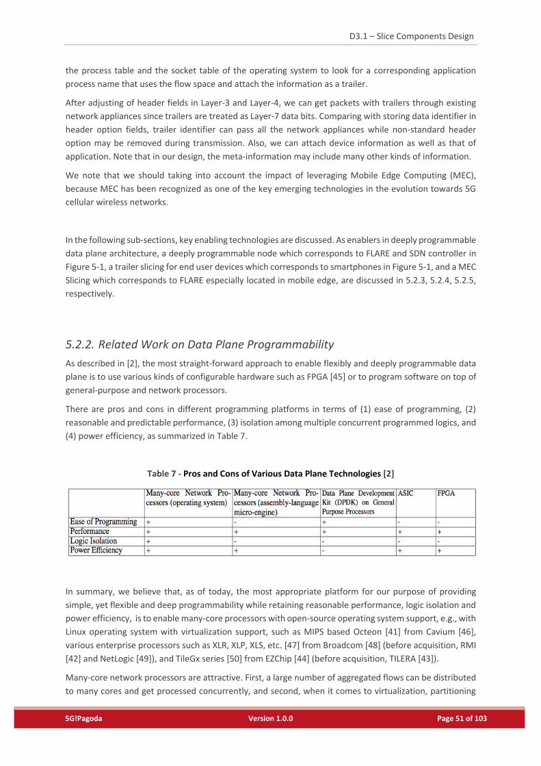
Table 7 - Pros and Cons of Various Data Plane Technologies [2] ..........................................................51
Table 8 – Example of mobility management feature of different network slices ................................83
Page 8
D3.1 – Slice Components Design
5G!Pagoda Version 1.0.0 Page 8 of 103
List of Figures
Figure 3-1 - Slice Template (Blueprint) .................................................................................................17
Figure 3-2 - End-to-End Network Slicing Framework ............................................................................18
Figure 3-3 - End-to-End Network Slice Architecture .............................................................................18
Figure 3-4 - Life-Cycle Orchestration Capability in Multi-Domain Environment ..................................19
Figure 3-5 - End-to-End Network Slice Architecture .............................................................................20
Figure 3-6 - Value added Services provided by Mobile Virtual Network Operators (MVNO) ..............21
Figure 4-1 - Example of a composed customized control plane ...........................................................23
Figure 4-2 - Functional approach ..........................................................................................................24
Figure 4-3 - Overall C-IoT EPS overview ................................................................................................27
Figure 4-4 - Core Network Decomposition ...........................................................................................29
Figure 4-5 - Interconnection and Routing Function (IRF) binding mechanism .....................................35
Figure 4-6 - Repository Function binding mechanism ..........................................................................36
Figure 4-7 - Dedicated protocols binding mechanism ..........................................................................37
Figure 4-8 - Shared Libraries binding mechanism .................................................................................37
Figure 4-9 - MF Binding Mechanisms ....................................................................................................38
Figure 4-10 - A dedicated slice perspective ..........................................................................................40
Figure 4-11 - Open5GCore, the lightweight version .............................................................................42
Figure 5-1 - Deeply Programmable Data Plane Architecture [3] ..........................................................50
Figure 5-2 - Parallel processing of packet flows in Lagopus data plane [9] ..........................................53
Figure 5-3 - Programmable Node Architecture [10] .............................................................................53
Figure 5-4 - Architecture of Application-Specific MEC Optimization [4] .............................................55
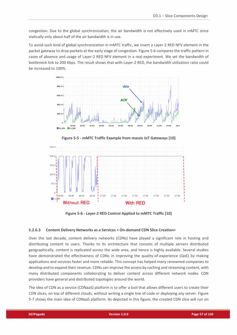
Figure 5-5 - mMTC Traffic Example from massic IoT Gateways [10] ....................................................57
Figure 5-6 - Layer-2 RED Control Applied to mMTC Traffic [10] ...........................................................57
Figure 5-7 - CDNaaS Platform Concept [10] ..........................................................................................58
Figure 5-8 - Use-cases of CDNaaS Platform [10] ...................................................................................58
Figure 5-9 - FLARE Hardware Architecture ...........................................................................................60
Figure 5-10 - FLARE Software Suite .......................................................................................................60
Figure 5-11 - eNB Slicing Configuration ................................................................................................61
Figure 5-12 - EPC Slicing Configuration [9] ...........................................................................................62
Figure 5-13 - Prototype System: Multiple MVNOs on top of Single Hardware ....................................63
Figure 5-14 - Prototype System Configuration .....................................................................................64
Figure 5-15 - Prototype System for ITU-T FG-IMT2020 Workshop & Demo Day .................................65
Page 9
D3.1 – Slice Components Design
5G!Pagoda Version 1.0.0 Page 9 of 103
Figure 5-16 - Proposed Architecture .....................................................................................................66
Figure 5-17 - End to End Slice vs Sub-slicing .........................................................................................67
Figure 5-18 - Sharing of a DP slice by two CP slices ..............................................................................67
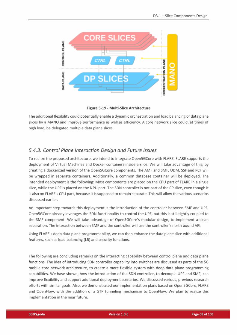
Figure 5-19 - Multi-Slice Architecture ...................................................................................................68
Figure 5-20 - Basic functions in NDN node ...........................................................................................70
Figure 5-21 - NDN Packet structure ......................................................................................................71
Figure 6-1 - NSP Framework .................................................................................................................73
Figure 6-2 - Initial configuration of simulation components ................................................................74
Figure 6-3 - Internal architecture of MMSC (Mobility Management Slice Component) ......................85
Figure 6-4 - Service-oriented architecture of MMSC ............................................................................87
Figure 6-5 - MMSC split between Common and Dedicated Slices ........................................................87
Figure 6-6 - APPA Algorithm .................................................................................................................91
Figure 6-7 - Tree Topology for VNF Placement close to Edge...............................................................92
Figure 6-8 - Basic Algorithm for Placing VNFs at Edge ..........................................................................93
Figure 6-9 - Algorithm for Placing VNFs at Edge, Moving Several Lower Priority VNFs........................93
Figure 6-10 - State Sharing and Load Balancing Mechanisms ..............................................................95
Page 10
D3.1 – Slice Components Design
5G!Pagoda Version 1.0.0 Page 10 of 103
Abbreviations
Throughout this document, the following acronyms, listed in Table 1, are used.
Table 1 - List of Acronyms
Abbreviations Original terms
3GPP The 3rd Generation Partnership Project
5G system The 5th Generation of Mobile Communications System
5GMF The 5th Generation Mobile Communications Promotion Forum
5GPPP The 5th Generation Infrastructure Public Private Partnership
B2B2C Business to Business to Consumer
CDN Contents delivery network
CDNaaS CDN as a Service
FANTASTIC-5G Flexible Air iNTerfAce for Scalable service delivery wiThin wIreless
Communication networks of the 5th Generation
FG IMT-2020 The Focus Group on network aspects of IMT-2020
IaaS Infrastructure as a Service
IMT International Mobile Telecommunications
IoT Internet of Things
ITU-T International Telecommunication Union Telecommunication Standardization
Sector
MEC Mobile Edge Computing
METIS-II Mobile and wireless communications Enablers for Twenty-twenty (2020)
Information Society-II
NFVI Network Function Virtualisation Infrastructures
NGMN Next Generation Mobile Network Alliance
RAN Radio access network
SDN Software Defined Networking
Page 11
D3.1 – Slice Components Design
5G!Pagoda Version 1.0.0 Page 11 of 103
SDO Standards Development Organization
uRLLC ultra-Reliable Low Latency Communications
VMN Virtual Mobile Network
VNF Virtualized Network Function
WP 5D Working Party 5D – IMT systems
Page 12
D3.1 – Slice Components Design
5G!Pagoda Version 1.0.0 Page 12 of 103
1. Introduction
1.1. Objectives
The objectives of Work Package 3 are to define a Lightweight Control Plane (Task 3.1), to define a Data
Plane Programmability (Task 3.2) and to define Slice Composition Algorithms and Mechanisms (Task 3.3).
The objective of this Deliverable D3.1 is to identify the definition and design of the various components,
functions, and interfaces which constitute the 5G!Pagoda end-to-end slicing architecture.
The technologies for realizing the slicing architecture, are categorized into network slicing mechanisms and
end-to-end slice orchestration mechanisms. This document is an initial report that mainly describes the
network slicing mechanisms, component design and algorithms, which are introduced as novelties in D2.3
“Initial report on the overall system architecture definition”. While more detailed investigation results are
explained in this deliverable, especially on light weight control plane, data plane programmability, and slice
composition algorithms.
These functions and mechanisms will be implemented, enhanced and deployed as integrated testbed
systems; afterwards various validation activities will be carried out as tasks in WP5 (Integrated testbed &
validation).
1.2. Motivation and Scope
In the recent years, there have been noticeable research initiatives on the 5th Generation of Mobile
Communications System (5G System), in Europe, Japan and worldwide. However, the focus has been
merely on high-level ideas and the generic directions that assume the use of software based solutions as
much as possible, while not considering the specific needs of either the orchestration mechanisms enabling
a multi-slice environment neither on the actual software network functions from which the service will be
composed of. A comprehensive and detailed 5G architecture is yet to be defined; leaving still space for
research and standardizations activities aiming to shape the 5G system architecture, one of the core
objectives of this 5G!Pagoda project.
It is generally agreed that cloud computing, Software Defined Networking (SDN) and Network Function
Virtualization (NFV) are key enabling technologies for future 5G mobile network. For example, ITU-T Focus
Group IMT-2020 identifies ‘network softwarization’ as one of the most crucial technology focus areas for
5G mobile networks. According to ITU-T, network softwarization is an overall transformation trend for
designing, implementing, deploying, managing and maintaining network equipment and network
components by software programming, exploiting characteristics of software, such as flexibility and
rapidity of design, development and deployment throughout the lifecycle of network equipment and
components, for creating conditions that enable the re-design of network and services architectures; allow
optimization of costs and processes; and enable self-management.
In the previous 5G!Pagoda deliverables: D2.1 “Use Case Scenarios, and Technical System Requirements
Definition –Ver. 1.1” ~ D2.3 “Initial report on the overall system architecture definition”, we have carefully
analyze requirements and use cases on 5G systems, and have defined 5G!Pagoda architecture which
includes an end-to-end 5G mobile networks slicing and a multi-domain slice orchestration functions as
unique and novel contributions. According to the significant efforts on 5G!Padoda architecture, work
Page 13
D3.1 – Slice Components Design
5G!Pagoda Version 1.0.0 Page 13 of 103
package 3 (WP3) aims to provide the fundamental functionality within the different network slices along
with the supporting mechanisms. The functionality includes the design and implementation of a highly
reconfigurable lightweight control plane, a highly programmable data plane mechanisms, and a set of
mechanisms for enhancing flexibility, elasticity, reliability of VNF control.
As an initial WP3 deliverable, the scope of this document is summarized as the below:
Detailed study and definition of all components that constitute the slice architecture in order to
realize the 5G!Pagoda architecture and slicing framework.
Design and specification of mechanisms to implement unique and disruptive 5G end-to-end
network slicing technologies.
Detailed technical explanations about Lightweight Control Plane, Data Plane Programmability,
Slice Composition Algorithms and Mechanisms (Design Framework).
Planning of necessary further studies including platform integration and use-case applications
development.
1.3. Relationships with other WPs
The relationships with other WPs are summarized as the below:
This document describes technical contributions for achieving 5G!Pagoda systems defined in WP2:
D2.1 - Use Case Scenarios, and Technical System Requirements Definition, D2.3 - Initial report on
the overall system architecture definition.
All of contributed technologies are key enablers for creating advanced 5G systems platform which
can deal with various business models described in D2.2 Initial business models, market analysis
and strategies for the adaptation of 5G!Pagoda concept.
The details on Operations and Management will be discussed in D4.1 “Scalability-driven
management system” as first deliverable from WP 4: End-to-End Slice Orchestration.
The results will be refereed in further investigation work of WP3 and in WP5: WP5 Integrated
testbed & validation.
1.4. Structure of the document
Following this introductory section, the remaining part of the document is structured as follows:
Section 2 provides the basic terminology used throughout this report. It includes the descriptions
of abbreviations, and technical terms.
Section 3 describes the 5G!Pagoda Architecture investigated in WP2 and deliverable D2.3 “Initial
report on the overall system architecture definition”.
Section 4 describes the Lightweight Control Plane investigated in Task 3.1.
Section 5 analyses the Data Plane Programmability investigated in Task 3.2.
Section 6 describes the Slice Composition Algorithms and Mechanisms investigated in Task 3.3.
Section 7 draws important concluding remarks and future work.
Page 14
D3.1 – Slice Components Design
5G!Pagoda Version 1.0.0 Page 14 of 103
2. Terminology
Table 2 a list of terms used in this document along with their definitions.
Table 2 - Terms defined in this document.
Terminology Definition
The 5h Generation of Mobile
Communications System (5G
System)
The proposed next major phase of mobile telecommunications
standards beyond the current 4G/IMT-Advanced standards. Rather
than faster peak Internet connection speeds, 5G system planning
aims at higher capacity than the current fourth generation of mobile
communication system, allowing higher number of mobile
broadband users per area unit, and allowing consumption of higher
or unlimited data quantities in gigabyte per month and user[22].
Business-to-Business-to-
Consumer (B2B2C)
An emerging e-commerce model that combines Business to
Business (B2B) and Business to Consumer (B2C) for a complete
product or service transaction. B2B2C is a collaboration process
that, in theory, creates mutually beneficial service and product
delivery channels[23].
Cloud computing A type of Internet-based computing that provides shared computer
processing resources and data to computers and other devices on
demand. It is a model for enabling ubiquitous, on-demand access to
a shared pool of configurable computing resources (e.g., computer
networks, servers, storage, applications and services) [24].
Software Defined Networking
(SDN)
A network architecture concept that allows network administrators
to manage network services through abstraction of lower-level
functionality. SDN is meant to address the fact that the static
architecture of traditional networks doesn't support the dynamic,
scalable computing and storage needs of more modern computing
environments such as data centres[25].
Slice An isolated collection of programmable resources to implement
network functions and application services through software
programs to accommodate individual network functions application
services within each slice without interfering with the other
functions and services on the other slices[9].
Network Function Virtualisation
(NFV)
A network architecture concept that uses the technologies of IT
virtualization to virtualize entire classes of network node functions
into building blocks that may connect, or chain together, to create
communication services[26].
Virtualized Network Function
(VNF)
Software implementations of network function that can be
deployed on a Network Function Virtualization Infrastructure[26].
IMT-2020 A provisional name of equivalent standard on 5G system defined in
ITU-R WP 5D[27].
Working party 5D – IMT systems A standard community responsible for the overall radio system
aspects of International Mobile Telecommunications (IMT) systems,
comprising the IMT-2000, IMT-Advanced and IMT for 2020 and
beyond[27].
Page 15
D3.1 – Slice Components Design
5G!Pagoda Version 1.0.0 Page 15 of 103
Network Softwarization An overall transformation trend for designing, implementing,
deploying, managing and maintaining network equipment and
network components by software programming, exploiting
characteristics of software such as flexibility and rapidity of design,
development and deployment throughout the lifecycle of network
equipment and components, for creating conditions that enable the
re-design of network and services architectures; allow optimization
of costs and processes; and enable self-management[28].
5G!Pagoda A research project federating Japanese and European 5G system
testbeds to explore relevant standards and align views on 5G system
mobile network infrastructure supporting dynamic creation and
management of network slices for different mobile services.
Slices of virtual mobile networks A logical instantiation of a mobile network possible to create with
both legacy platforms and network functions, but substantially
lower barriers to using the technology, for example through
increased flexibility and decreased costs.
Mobile slice A slice of virtual mobile networks
The 3rd Generation Partnership
Project (3GPP)
A collaboration between groups of telecommunications
associations, known as the Organizational Partners. The initial scope
of 3GPP was to make a globally applicable third-generation (3G)
mobile phone system specification based on evolved Global System
for Mobile Communications (GSM) specifications within the scope
of the International Mobile Telecommunications-2000 project of
the International Telecommunication Union (ITU[21]). The scope was
later enlarged to include the development and maintenance of:
GSM and related “2G” and “2.5G” standards including GPRS and
EDGE, UMTS and related “3G” standards including HSPA, LTE and
related “4G” standards, an evolved IP Multimedia Subsystem (IMS)
developed in an access independent manner, and next generation
and related “the fifth generation” standards[29].
Next Generation Mobile
Networking Alliance (NGMN)
A mobile telecommunications association of mobile operators,
vendors, manufacturers and research institutes. It was founded by
major mobile operators in 2006 as an open forum to evaluate
candidate technologies to develop a common view of solutions for
the next evolution of wireless networks. Its objective is to ensure
the successful commercial launch of future mobile broadband
networks through a roadmap for technology and friendly user trials.
Its office is in Frankfurt, Germany[17].
Internet of Things (IoT) The internetworking of physical devices, vehicles (also referred to as
“connected devices” and “smart devices”), buildings and other
items - embedded with electronics, software, sensors, actuators,
and network connectivity that enable these objects to collect and
exchange data. In 2013, the Global Standards Initiative on Internet
of Things (IoT-GSI) defined the IoT as “the infrastructure of the
information society”.
The 5h Generation Infrastructure
Public Private Partnership
A group initiated by the European Commission and industry
manufacturers, telecommunications operators, service providers,
Page 16
D3.1 – Slice Components Design
5G!Pagoda Version 1.0.0 Page 16 of 103
SMEs and researchers. It aims to deliver solutions, architectures,
technologies and standards for the ubiquitous next generation
communication infrastructures of the coming decade[20].
FANTASTIC-5G A research project funded by HORIZON2020 consisting of 16
telecom players that aim to develop a new air interface below 6 GHz
for 5G networks[18].
Mobile and wireless
communications Enablers for
Twenty-twenty (2020)
Information Society-II (METIS-II)
A research project aiming to develop the overall 5G radio access
network design and to provide the technical enablers needed for an
efficient integration and use of the various 5G technologies and
components currently developed. It provides the 5G collaboration
framework within 5GPPP for a common evaluation of 5G radio
access network concepts and prepare concerted action towards
regulatory and standardisation bodies[19].
The 5th Generation Mobile
Communications Promotion
Forum (5GMF)
A group actively promoting 5G system study in line with trends both
in Japan and abroad based on a roadmap on 5G system
implementation policy published by the government of Japan[30].
Mobile Edge Computing (MEC) A network architecture concept that enables cloud computing
capabilities and an IT service environment at the edge of the cellular
network. The basic idea behind MEC is that by running applications
and performing related processing tasks closer to the cellular
customer, network congestion is reduced and applications perform
better[32][36-38].
Contents Delivery Network (CDN) A globally distributed network of proxy servers deployed in multiple
data centres. The goal of a CDN is to serve content to end users with
high availability and high performance. CDNs serve a large fraction
of the Internet content today, including web objects (text, graphics
and scripts), downloadable objects (media files, software,
documents), applications (e-commerce, portals), live streaming
media, on-demand streaming media, and social networks[31][35].
Quality of Experience (QoE) A measure of a customer's experiences with a service (web
browsing, phone call, TV broadcast, call to a Call Centre). QoE
focuses on the entire service experience, and is a more holistic
evaluation than the more narrowly focused user experience
(focused on a software interface) and customer-support experience
(support focused) [33].
Page 17
D3.1 – Slice Components Design
5G!Pagoda Version 1.0.0 Page 17 of 103
3. 5G!Pagoda Architecture
3.1. Slice Architecture [defined in D2.1]
One of the key targets of the upcoming 5G systems is to build a novel network architecture that shall
support not only classical mobile broadband applications and services, but also vertical industries (e.g.
automotive systems, smart grid, and public safety) and IoT-based services. Besides devices operated
by human (i.e. smart-phones and tablets), 5G systems will also include sensors, actuators and vehicles.
All these requirements have been driven by the envisioned 5G system use-cases. Indeed, several SDOs
and ongoing 5G research projects have defined different 5G system use-cases with different targets.
Network Slicing are recognized as one of most the important technical topics in promotion and
standardization bodies such as 3GPP, ITU-T, and 5GMF towards successful 5G launch 2020 and beyond. A
Slice is defined as a virtualized (i.e., logical) network consisting of virtual resource and executable functions.
Each slice is isolated in order to avoid being affected by the all of changes in other slices. Furthermore, each
slice can be deployed in recursive and multi-domain manner for cost effective operations of very large and
complex 5G systems.
In order to define high level architecture (blueprint) of slices, a slice template is introduced, as a basic slice
structure as illustrated in Figure 3-1. The slice template consists of resources and multiple function modules
in data/user plane, control plane, service plane, and management plane. SDN technology realizes a
softwarization of control plane functions, and it enables to customize flow based packet processing
behaviors thanks to logically centralized network controller. NFV technology realize a softwarization of
sophisticated service functions such as advanced security and traffic steering mechanisms thank to
interworking with software defined control plane and data plane functions.
By creating different slices for eMBB, mMTC, and URLLC applications, each slice enables to customize its
capability of data plane, control plan, service plan, and management plane, in order to satisfy different
system requirements in QoS related parameters (bandwidth, throughput, latency, jitter), secure and
reliable capabilities.
Figure 3-1 - Slice Template (Blueprint)
Page 18
D3.1 – Slice Components Design
5G!Pagoda Version 1.0.0 Page 18 of 103
Figure 3-2 illustrates an example of launching multiple network slices over a physical infrastructure. It is
very important that the virtual resources are isolated from such impact factors as communication quality,
performance, and functions, in order not to interfere such factors with each other. A life-cycle management
plane is responsible for administrating and coordinating such virtual resource utilization in order to keep
slice isolation capability. The life-cycle management plane enables to monitor resource status, to control
resource scheduling, and to manage optimized resource utilization even if the sudden and unpredictable
changes (failures, the number of users, traffic demands) arise.
Figure 3-2 - End-to-End Network Slicing Framework
Figure 3-3 shows End-to-end network slice architecture applying 3GPP standardized mobile
communication functions into 5G!Pagoda’s slice template. The slice template enables to define mobile and
wireless networks, backbone networks, computer and storage resources as virtual resources, and enables
to configure a network slice from software components using those virtual resources.
Figure 3-3 - End-to-End Network Slice Architecture
Page 19
D3.1 – Slice Components Design
5G!Pagoda Version 1.0.0 Page 19 of 103
3.2. Multi-domain Orchestration Architecture [defined in D2.1]
One of the differential contributions from 5G!Pagoda is a multi-domain orchestration architecture. The
characteristics 5G!Pagoda multi-domain orchestration are highly scalable and flexible based on our scalable
management capabilities and single- / multi-domain slice operations & management capabilities.
Since a network slicing is generally extended around multiple networks (i.e. wireless, access, transit, and
backbone) and multiple providers (i.e. network operators, ISPs, xSPs, and cloud operators), it is very
important to deal with multi-domain operations and management where there is technology convergence
with different policies.
E2E network slicing architecture in multi-domain environment is depicted in Figure 3-4. We should have a
domain-specific slice orchestrator and a multi-domain slice orchestrator functions. Those functions should
interact with each other, moreover, they should be responsible for dynamic adaptation which is on-
demand and flexible system re-configuration capability for planed and unpredictable changes in user
behaviors, traffic demands, operation policies, and failures.
The domain-specific slice orchestrator is responsible for all operations and management in single domain,
and multi-domain slice orchestrator is expected to coordinate total operations of individual operation.
Figure 3-4 - Life-Cycle Orchestration Capability in Multi-Domain Environment
Page 20
D3.1 – Slice Components Design
5G!Pagoda Version 1.0.0 Page 20 of 103
3.3. Reference Architecture [defined in D2.3]
As a reference, the generalized 5G!Pagoda architecture for single-domain slicing is illustrated in Figure 3-5.
The Infrastructure consists of resources that are separated into two main groups:
Virtual Computing/Storage/Connectivity Resources (i.e. interconnected data centers) that are build
atop of respective Physical Resources.
Hardware Nodes and Subsystems (HNS) that can be used by the Common Slice or Dedicated Slices.
HNS may include RAN or Radio Nodes (eNBs), specific transport nodes, etc. These nodes can be also
programmed, but they offer different services than virtual connectivity/storage or computing.
Both types of resources can be dynamically allocated to slices. The allocation of Infrastructure resources
to the Slice Resource Layer is done by the Intra-Domain Slice Orchestrator and is optimized during whole
life-cycle of the slice. The detailed functionality of Intra-Domain Slice Orchestrator will be discussed in D4.1.
The architecture allows for two different generic slice types: Common Slices and Dedicated Slices. All the
slices can cooperate; because of this, they share a similar internal structure (Control, Data, Application and
Management Planes and Slice Operations Support functions). Both types of slices, despite they have similar
architecture, have different roles or are complementary ones – it can be said that the Dedicated Slice is a
client of the Common Slice.
Hardware Nodes (PNFs) and Subsystems (HNS) Physical Computing/Storage/Connectivity Infrastructure Layer (PCSCI)
Virtual Computing/Storage/Connectivity Infrastructure Layer (VCSCI)
Intra-domainSlice
Management and
Orchestration(IDSMO)
Slice #1 operator
Slice #n operator
Common Slice
operator
Orchestrator operator
Infrastructure
Intra-domainSlicing
(Single operator)
Slice Resource Layer (SRL)
Slice Sofware Layer (SSL)
SliceOperations
Support
Common Slice ownedHNS
SliceManagement
Plane
Common Application Plane
Common Control Plane
Common Data Plane
CommonSlice Slice Resource Layer (SRL)
Slice Sofware Layer (SSL)
SliceOperations
Support
Common Slice ownedHNS
SliceManagement
Plane
Common Application Plane
Common Control Plane
Common Data Plane
CommonSlice
Slice Resource Layer (SRL)
Slice Sofware Layer (SSL)
SliceManagement
Plane
Slice Data Plane
Dedicated Slice #1
Slice ownedHNS
SliceOperations
SupportSlice Data Plane
Slice Data Plane
Slice Resource Layer (SRL)
Slice Sofware Layer (SSL)
SliceManagement
Plane
Slice Data Plane
Dedicated Slice #1
Slice ownedHNS
SliceOperations
SupportSlice Data Plane
Slice Data Plane
Dedicated Slice #nSlice Resource Layer (SRL)
Slice Sofware Layer (SSL)
SliceManagement
Plane
Slice Data Plane
Slice ownedHNS
SliceOperations
SupportSlice Data Plane
Slice Data Plane
Slice Resource Layer (SRL)
Slice Sofware Layer (SSL)
SliceManagement
Plane
Slice Data Plane
Slice ownedHNS
SliceOperations
SupportSlice Data Plane
Slice Data Plane
Hardware Nodes (PNFs) and Subsystems (HNS) Physical Computing/Storage/Connectivity Infrastructure Layer (PCSCI)
Virtual Computing/Storage/Connectivity Infrastructure Layer (VCSCI)
Intra-domainSlice
Management and
Orchestration(IDSMO)
Slice #1 operator
Slice #n operator
Common Slice
operator
Orchestrator operator
Infrastructure
Intra-domainSlicing
(Single operator)
Slice Resource Layer (SRL)
Slice Sofware Layer (SSL)
SliceOperations
Support
Common Slice ownedHNS
SliceManagement
Plane
Common Application Plane
Common Control Plane
Common Data Plane
CommonSlice
Slice Resource Layer (SRL)
Slice Sofware Layer (SSL)
SliceManagement
Plane
Slice Data Plane
Dedicated Slice #1
Slice ownedHNS
SliceOperations
SupportSlice Data Plane
Slice Data Plane
Dedicated Slice #nSlice Resource Layer (SRL)
Slice Sofware Layer (SSL)
SliceManagement
Plane
Slice Data Plane
Slice ownedHNS
SliceOperations
SupportSlice Data Plane
Slice Data Plane
Figure 3-5 - End-to-End Network Slice Architecture
Page 21
D3.1 – Slice Components Design
5G!Pagoda Version 1.0.0 Page 21 of 103
3.4. Emerging Role of MVNO
As one of the differentiated contributions of 5G!Pagoda, we discuss the emerging role of Mobile Virtual
Network Operators (MVNO) as a new stakeholder in the 5G/IoT era. It is no doubt that the role of MVNO
is becoming more important. MVNO provides with sophisticated services by extending basic
communication services which is usually provided by Mobile Network Operators (MNO). Different from
conventional Internet Service Providers (ISP), MEC resources and capabilities and programmable
networking nodes enable MVNO to provide end users with customized services like privacy treatment, IoT
security, reliability, load balancing as well as fine-grained QoS.
Figure 3-6 shows some of business examples in vertical segments; health, transportation, hotel, and utility
industries. In the middle between mobile access networks and cloud data centers, networks and computers
(i.e., programmable network nodes) are instrumented, then (1) advanced value added services by MEC,
and (2) network slices customization optimized for users and industrial segments, are provided. The
examples of value added functions are privacy, security, real-time and dynamic reconfiguration reliability,
and traffic local balancing. Those functions enable to provide with various capabilities to achieve IoT
devices and clouds interaction and multiple service collaboration, and to achieve new business creation.
Data plane programmability is able to achieve this sort of dynamic service infrastructure thanks to the
introduction of new capabilities in cost-efficient manner, then to accelerate fair competition for creating
new business environment.
Figure 3-6 - Value added Services provided by Mobile Virtual Network Operators (MVNO)
Network Slice which is customized
& optimized for Industries / users
NESIC
Datacenter
Public Clouds
Cloud Service Provider
( MVNO Serviced provided by NESIC(
Health
Transportation
Hotel
Utilities
Transportation Service Platform
Health Service Platform
Data Sharing
On Premises
Hotel Service Platfor
5G/LTE
(Multi-Carriers)
LTE
over
WiFi
ZigBee
Bluetooth
Ø Network Slicing as a ServicesØ Operations and Management by
Different Policies
Value added Services
near end-users (MEC)
Nets Wireless
Page 22
D3.1 – Slice Components Design
5G!Pagoda Version 1.0.0 Page 22 of 103
3.5. 5G!Pagoda Original and Unique Contributions
As described in D2.3 “Initial report on the overall system architecture definition”, there are many technical
contributions from 5G!Pagoda. Among those, our novelties from infrastructure components design
viewpoint are listed as the following;
Flexible Control Plane for reusable and customizable networking,
Data Plane Programmability to improve the CURRENT and to create NEW (Protocols and Services),
Design and Planning Framework for virtual resource optimization,
Slice Stitching (which is the responsible scope of WP4 / D4.1),
Orchestration Frameworks (which is also the responsible scope of WP4 / D4.1).
As the more focused viewpoint on slice components design, we believe a lightweight control plane (related
to T3.1), a data plane programmability (related to T3.2), and a slice planning (related to T3.3) are the
focused points to contribute. These are discussed in more detail at the succeeding sections.
5G!Paoda uniqueness from business viewpoint, which is extracted from D2.2, can be listed as the following;
Short Time to Market (TTM) Deployment,
Reconfigurable Capabilities for Scalable, Reliable, and Stable Services,
Improvements of High Performance and Optimized Capabilities.
These are very important to establish a promising 5G!Pagoda architecture, in order to deal with various
business models and stakeholders in all kinds of 5G verticals. We should take them into account on the
following discussions in order to differentiate our technical contributions from conventional technologies,
then to keep our uniqueness and originality for the future innovations.
Page 23
D3.1 – Slice Components Design
5G!Pagoda Version 1.0.0 Page 23 of 103
4. Lightweight Control Plane
In this section, a comprehensive solution for providing a lightweight control plane functionality as well as
a mechanism to be able to extend the lightweight functionality with added value functionality is described.
The solution is carefully designed to address the requirements of the different use cases in a proper
manner.
Figure 4-1 - Example of a composed customized control plane
Three key technologies are assessed and developed in the context of the 5G control plane functionality
and further described in this section:
Splitting of the functionality of the control plane into a set of functional features at the
granularity level which enables their re-composition according to properly address the
requirements of the use cases.
Selecting of the minimal functionality from which the lightweight control plane is composed
of. This represents the minimal functionality which can run as a core network considering the
current 5G scenarios.
Development of a set of proper composition mechanisms through which the lightweight core
network can be extended with additional added value functional features in order to obtain
customized core networks
Additionally, this section includes the description of the integration between the control plane and the
data plane, especially towards the integration with the deep data plane functionality as presented in
Section 5.4.
Page 24
D3.1 – Slice Components Design
5G!Pagoda Version 1.0.0 Page 24 of 103
4.1. Problem Statement
4.1.1. Motivation
In the 3GPP TR 23.799 “Architecture and Security for Next Generation System” which addresses the key
challenges in the definition of the 5G network system architecture, the key issue number 7 addresses
‘Network function granularity and interactions between them’. The 3GPP TR assumes that the next
generation system should be designed as a highly flexible architecture, consisting of dynamic deployment
of functions and high function re-usability in terms of ease of interfacing, flexible chaining and co-location
of network functions. In addition, the deployment of new services should be performed in an agile and
rapid way as a result of fast communication mechanisms between lightweight network functions.
In order to achieve these requirements, the functional granularity of network functions needs to be
defined, including the identification of functions inter-dependency and the support of flexible inter-
connection between them, which is exactly mapped to the goal of the developments reported in this
section.
4.1.2. Goals
5G!Pagoda T3.1 aims to design a lightweight control plane as the fundamental piece of a network slice, to
which different functions can be incrementally added, depending on what type of service the network slice
is going to provide to the end users. In other words, a “minimal slice”, recognized as lightweight control
plane, is the minimal core network and is composed by the smallest number of control plane functionalities,
such as reliability, security, mobility and QoS. However, this “minimal slice” can be further expanded with
specific add-ons in order to build customized end-to-end services. Thus, functionalities can be easily
combined together starting from a set of common control plane functions, providing a highly flexible
environment where different services (described as composition of small granularity functions) can be
deployed, as required by the next generation architecture.
As described in Figure 4-2, the adopted approach to implement the functionality was divided into five
different steps that lead to the definition of the lightweight control plane and the different service
configurations enabling the evolution starting from the 3GPP 4G Evolved Packet Core and completing it
with the 3GPP 5G system.
Figure 4-2 - Functional approach
Page 25
D3.1 – Slice Components Design
5G!Pagoda Version 1.0.0 Page 25 of 103
First, the existing EPC will be decomposed into highly granular functions for the control plane, such as
access control, connectivity control, security, mobility, QoS and charging. These functions will be further
decomposed into atomic control plane functions, minimal functional blocks used to build highly customized
service instances.
Second, the functionalities will be classified into mandatory, optional and specific add-ons, depending on
the importance that the atomic functions have for the final architecture, as well as for the required
flexibility (e.g. if the function is common between different components or has different parameters,
protocol, etc.). The expected outcome of this second step, will be a map of connectivity features from
different high level functionality perspectives.
Afterwards, the focus will be on the binding mechanisms necessary to efficiently connect control functions
within a single service instance. Four mechanisms have been identified (see section 4.3), taking into
consideration the service reliability and flexibility, the end-to-end configuration and service dimensioning
and the mechanism for a network function to interconnect to its peer instances (e.g. via provisioning,
selection and discovery, etc.). These mechanisms enable the deployment of the functionality into
customized control plane deployments
Furthermore, the complete view will be provided at service level: a lightweight control plane on top of
which additional functions eventually lie, forming the required services. Finally, automatic testing, runtime
adaptations and continuous development will be performed in order to manage the network function
instances life cycle, especially towards addressing requirements which do not directly refer to additional
functionality brought in the core network such as dimensioning and scalability, security and resilience,
through this completing the 5G system.
In this specification only the steps of functional decomposition, the lightweight core network and the
binding mechanisms are presented while the service levels definition and the life-cycle agility will be
included in the next deliverables.
4.1.3. Key Supporting Technologies
In order to model and design the lightweight control plane architecture, two mechanisms have been
considered. The first one is related to the recently introduced technology called micro-services that consists
in a distinctive method of developing software systems. This is currently named network function services
in the context of the 5G system development (see 3GPP TS 23.501).
The second is the new IoT core network that has been recently standardized by 3GPP as extension of the
4G Evolved Packet Core and takes into consideration for basic connectivity functionalities and support for
small data transfer, specifically aiming to develop a lightweight core network functionality for a very large
number of connected devices.
4.1.3.1 Micro-services
Key element to understand how the different functionalities are decomposed within the lightweight
control plane and how their interconnection mechanisms work, is the concept which lays behind the term
“micro-service”.
Page 26
D3.1 – Slice Components Design
5G!Pagoda Version 1.0.0 Page 26 of 103
It specifically refers to a highly-modularized approach to software implementation. Although there isn’t a
precise definition of this architectural style, some common characteristics in terms of automated
deployment, decentralized control and intelligence at function level can be identified.
In a micro-services architecture, each application is split into atomic services which are implemented and
deployed separately, running in own processes. Compared to a monolithic application built as a single unit,
micro-service architecture puts each element of functionality into a different service and scales by
distributing these services across servers, replicating them as needed. Through these means, two major
effects are obtained.
First, the atomic services can be implemented independently of the others, thus giving a high
independence for the implementation to the specific developers and thus to be able to optimize the
specific functionality.
Second, the atomic services can be composed in different customized applications and ultimately new
applications can be created very easily by combining existing atomic services and building only some added
value ones, through this increasing the flexibility and the degree of the customization required.
The atomic services are communicating using specific mechanisms that come from the networking
environment such as HTTP REST or through IPC communication. These mechanisms have various benefits
such as redundant deployments and elastic scaling.
Due to their specific, the addition of new micro-functions to an application is possible only by using the API
of the existing micro-services, ultimately the composition of a new application boiling down to the building
on top of the existing micro-services APIs of new micro-services, similar to the building of software
programs using the existing operating system libraries.
The main issue of this kind of approach and its application towards the 5G core network is the overhead of
the system. Specifically, in order to communicate between any of the atomic services, the messages have
to be encoded into the specific HTTP REST messages and sent over the network and then to be responded
by the other entity through the decoding of the message and its processing. When a message has to pass
through multiple atomic services during a transaction, the result is that multiple communications between
the atomic services will have to be realized thus resulting into an increased end-to-end delay of the
procedure.
Additionally, due to their isolation, the many micro-services need to be handled independently in terms of
life-cycle and dependencies management, deployment and monitoring, resulting into a large scalability
problem.
Although in this specification, the main concept if micro-services are taken into consideration for the
implementation of the customized control plane functionality on top of a lightweight core network, it will
be adapted to the specific delay and management requirements needed for carrier grade 5g systems [59].
4.1.3.2 C-IoT EPS Optimization
Up to the Release 13, the 3GPP 4G Evolved Packet Core was mainly concerned with the increase of the
broadband communication characteristics per device, thus mainly on the transmission of overall more data
over the radio environment. With the Release 14, and the standardization of the Narrow-Band IoT (NB-IoT)
extensions, a turn was taken towards the support of a massive number of devices with low amount of
information which has to be transmitted, which turn will be continued with the evolution towards the 5G
system.
Page 27
D3.1 – Slice Components Design
5G!Pagoda Version 1.0.0 Page 27 of 103
From the Core Network point of view, the new feature is referred to as Non-IP Data Delivery (NIDD) and it
is part of the Cellular-IoT EPS Optimizations [58]. The architecture is showed in the following Figure 4-3,
underlining the new and the modified components.
Figure 4-3 - Overall C-IoT EPS overview
The NIDD functionality provides efficient support for infrequent small data transmission while minimizing
radio and network signalling. Data bearer assignment is no longer needed, as the user data payload is
encapsulated user data payload into NAS signalling messages. As a consequence, user data is using the
packet core messaging service and not a data path in the strict sense.
The messages are transported in a secure manner over the Service Capability Exposure Function (SCEF)
between the MME which exchanges the messages with the UE and the C-IoT services. SCEF is a new
component especially designed for Non-IP Data Delivery (NIDD) over control plane and as interface towards
the application layer, providing the means to securely expose the service and capabilities provided by 3GPP
network interfaces. Although a proof-of concept SCEF is implemented, this specification will be concerned
with the main core network functionality and not with interworking functions with applications such as
SCEF.
From the perspective of this specification, the C-IoT functionality represents a first attempt to define a
lightweight core network, on top of existing high capacity carrier-grade 4G Evolved Packet Core, thus acting
mainly as an add-on and not as a simplification of the functionality. However, this functionality may be
separated into a dedicated lightweight core network and further adapted based on the principles described
in the next sections to become a truly adaptable core network which addresses the requirements of the
specific services within a slice.
Minimal connectivity functionalities are going to be provided over control plane as lightweight data plane
support. This means that the C-IoT optimization functionality will be considered as reference point for non-
IP delivery during the segmentation process of the control part of the plane.
Page 28
D3.1 – Slice Components Design
5G!Pagoda Version 1.0.0 Page 28 of 103
4.2. Core Network Decomposition
For being able to define a lightweight core network a first step that has to be taken is to analyse in detail
the different functionalities of the core network and to decompose them into atomic units with the
consideration that the atomic services represent the minimal type of functionality which makes sense to
be implemented independently (assuming that the benefits of its implementation are less than the cost of
the integration based on the expert evaluation of the members of the consortium).
The decomposition follows the major high level functionality needed in a packet core. Specifically, four
directions are adopted, matching the ones in the 5G Next Gen core network evolution in 3GPP: Security,
Access (Control), Mobility and Session management. Additionally, in each of the high-level functionality
areas, the decomposition is following two major directions:
Splitting of the functionality into different directions - cutting a function into two pieces each
having a different functionality, similar to the micro-services approach
Added value of functionality - a new micro-function could build on top of an existing micro-
function and provide some added value functionality to the one provided by the basis micro-
function.
The result of this exercise is a set of functions which may be included in a specific service. Based on this, in
the following sections a set of customized control plane deployment models are developed as well as the
means for their integration.
4.2.1. Definition of micro-functions
Before aiming to decompose the current packet core architecture to a set of micro-functions, additional
considerations have to be made on the goal and the process of the decomposition. Specifically, there are
functions which may worth to be split while there are functions which should remain together due to a
clear efficiency when they are grouped.
An immediate porting to a micro-services architecture into the core network context may be not efficient
enough. Specifically, the current core network was designed to have a state machine in each of the
components. The communication between the different components represents practically the
communication between the state machines. The moment that a core network is decomposed in micro-
services, a careful consideration has to be given to these two elements: state machines and how the
subscriber state is maintained and the communication between the entities.
An integrated state machine represents a very large advantage in terms of processing compared to two
split ones. This is mainly because the state of the subscriber is maintained into a single data base which has
to be accessed twice: once at the beginning of the processing of a message to gain information on the
existing subscriber state and once at the end of the processing when the subscriber state is updated. When
having a split state machine this process has to be executed twice, once for each of the machines, thus a
common state being better in terms of functionality needed, scalability and delay.
Additionally, the interactions between the micro-services require a certain formatting of the exchange
messages which have to be encoded and decoded and a transaction mechanism ensuring the reliable
communication (e.g. through acknowledged messages). Because of this, between two micro-services
ultimately an interface has to be defined. However, as the micro-services may be grouped in the same
Page 29
D3.1 – Slice Components Design
5G!Pagoda Version 1.0.0 Page 29 of 103
network functions and may use the same communication primitives (such as in the case of bus
communication) several optimizations are considered and presented in the next sections.
As a result, based on the definition of micro-services, a similar architecture has been considered in order
to define a lightweight architecture that could properly fit with a core network environment. Starting from
this, the term “micro-function” has been coined to identify small granularity control plane functions that
communicate with lightweight mechanisms and can be deployed independently to each other.
On the other hand, the micro-functions based architecture brings a very high level of function reusability
and efficiency through the deployment of customized network infrastructures in parallel slices completely
tailored to the specific service needs. Additionally, a large number of smaller functions are easier to adapt,
customize and extend.
Figure 4-4 - Core Network Decomposition
The initial core network decomposition is illustrated in Figure 4-4 following the four main high level
functions of the core network. As a proof of concept, only this functionality is considered, the rest of the
functions having to pass through the same process (including charging, lawful interception, location
service, etc.).
The high-level functionality on security refers to the privacy of the end-to-end communication across the
system (i.e. the encryption). This has to be differentiated from the safety part of security where the
network has implemented different mechanisms including access control, mobility and session
management ones and enables the network to run a secure service to the subscriber against different types
of attacks. As the functionality of safety is split between the different functions and as it relates very close
to the reliability, safety will be analysed with the other add on features and presented in the next
deliverable.
Access control is the high-level functionality which enables the subscribers to get authenticated and
authorized to use the service.
Page 30
D3.1 – Slice Components Design
5G!Pagoda Version 1.0.0 Page 30 of 103
Mobility management is the high-level functionality of the control plane which manages the reachability
and the continuity of communication of the devices while being mobile through the targeted access
network(s).
Session management represents the high-level functionality in the control plane which establishes the
quality of the end-to-end data path in terms of resources allocated for enabling the communication. The
concept of session is adopted directly from the telecom networks and it assumes that before establishing
any end-to-end communication a data path should be established through signalling. This concept can be
extended also for messaging for example where the default connectivity acts as the session.
4.2.2. Security micro-functions
From the perspective of the privacy of the communication across the network, three major levels can be
defined depending on the partial or complete securing of the communication channel. From a control plane
perspective, the securing of the communication channel presents the most importance as it presumes that
a security association is made between the device and the network in such a manner in which the
communication will be encrypted across the data channel.
The encryption over the network is implemented as part of IPsec tunnels which have to be established for
each of the specific bearers. This is most important for the use cases in which the data traffic passes through
transport networks which do not pertain to the same operator such as in the case when the network slice
is deployed on top of two different trusted NFV Infrastructures.
For the radio security, there are specific mechanisms not under the consideration for the core network
functionality on how encryption keys can be generated directly from the authentication of the subscriber
and from the channel allocation, mechanism which was first introduced with 3G and was ported to 4G.
Table 3 - Security Micro-Functions
Micro-function class Description Considerations
Unsecured The communication between the device
and the network is not secured.
No functionality is needed in the
network.
Unsecured over
network
The communication is secure only on the
radio channels and not over the core
network.
The functionality of securing the
communication is part of the radio
networks.
Secured over
network
Completely secured communication on
both radio and network channels.
Additional functionality has to be
added to the subscriber
communication management
function.
Page 31
D3.1 – Slice Components Design
5G!Pagoda Version 1.0.0 Page 31 of 103
4.2.3. Access Control
The access control functionality is the related to the identification of the devices and their authentication
and authorization to use the connectivity service. There are several levels of access control which can be
conceived for a telecommunication system, levels which include the possibilities to interact with the
network (for which the devices are acquiring access for).
The basic access control is the identifier of the UE. The UE has to be able to transmit or receive data from
the network according to the specific communication service requirements. In order to be able to
determine where the data comes from or has to be sent to, there is a need to have a specific identifier for
the UE.
This identifier will guarantee a minimal service in terms of access control. The minimal service is the ability
to communicate in terms of reachability and communication across the environment. Virtually any device
which presents the correct identifier can transmit or receive data.
This identifier can be unique per subscriber or can be a token base system where UEs are using different
identifiers for each data session. Although a token system is probably the fastest mechanism to transmit
active data, as a token includes in itself the authentication and the authorization processes, these still have
to have been executed in a previous phase when the token was acquired.
A more complex version of access control would include as an extension of the identifier micro-function
also the authentication of the devices. From the perspective of this specification, the micro-service for
authentication can be implemented with one of the multiple possible implementations and only one per
slice. With this, the micro-service for authentication can be separated from the other micro-services and
can be implemented with the most appropriate mechanism within the slice.
The authentication micro-function can be extended to support a secure dual authentication in which also
the network authenticates to the device, as in the current 3G and 4G systems. This micro-function can be
an extension of the existing authentication micro-function or a replacement (i.e. a specific implementation)
which includes the secure authentication of the devices. The secure authentication presumes that data
acquired in the previous communication session, such as security keys are also used in the next session to
ensure the privacy of the communication.
After the execution of the authentication, the devices have to be authorized to use the service. Similar to
the authentication, this is done based on the subscription profiles of the devices and it includes a
description of the service that the subscriber is authorized to use starting from basic messaging to
continuous seamless sessions with guaranteed resources.
A combination of multiple of these is always possible with differentiated access control per data flow or
per application. Compared to the basic authorization, this presumes that additional authorization
mechanisms are deployed next to the basic authorization one in order to enable the parametrization of
the connectivity per application flow.
Page 32
D3.1 – Slice Components Design
5G!Pagoda Version 1.0.0 Page 32 of 103
Table 4 - Access Control Micro-Functions
Micro-function class Description
Identity The end user identify itself to the network using its
UE ID.
Authentication The network checks the identity of the end user.
Secure authentication The network authenticates the end user
performing the EPS-AKA procedure:
authentication vectors are generated by the
network in order to perform a mutual
authentication with the UE.
Authorization The network allows the establishment of the
default bearer for the end user.
Differentiated access control The network allows the establishment of
dedicated bearers for the end user and authorizes
different type of services.
4.2.4. Mobility
The core network should define the level of mobility support for a UE. The mobility management is mainly
based on end user reachability and different types of handover processes. As described in the following
table, reachability can be achieved in one direction (UE to network) or both, with only uplink or either
downlink connectivity capabilities. This means that an efficient support of small data packet and SMS is
provided over control plane and considered as part of the Cellular (C-IoT) EPS optimization [58]. On the
other hand, handovers can be handled with various guarantees in terms of packet loss and service
continuity. Lightweight control plane does not support any kind of evolved and complex mobility capability
to the end user, such as handover.
Table 5 - Mobility Micro-Functions
Micro-function class Description
Outbound reachability The UE can reach the network and transmit data.
Inbound reachability The UE is reachable from the network.
Basic data path The end user has only uplink connectivity capabilities.
Data path with inbound reachability The end user has both uplink and downlink connectivity
capabilities.
Page 33
D3.1 – Slice Components Design
5G!Pagoda Version 1.0.0 Page 33 of 103
Interrupted handovers The end user disconnects to one network and is
disconnected when handover is performed. Packet loss.
Continuous procedure (hard) handovers Break-before-make handover. The connection to the
source is broken before the connection to the target is
made. Packet loss.
Zero-packet loss (soft) handovers Make-before-break handover. The connection to the
target is established before the connection to the source is
made. No packet loss.
Seamless handovers Handover takes place without perceptible interruption of
the radio connection. No disconnection, no packet loss.
4.2.5. Session Micro-Functions
The core network should provide communication session support for a wide range of use cases for different
access technologies (i.e. 3GPP access and non 3GPP access), being completely harmonized with the E2E
QoS control solution in RAN, core and transport network. Furthermore, it should be able to properly
identify the multiple QoS parameters (i.e. maximum bit rate, guaranteed bit rate, priority level) as well as
the required QoS granularity (i.e. per UE, per flow).
Table 6 describes how session functionality, exposed by core network control plane, have been identified
in micro-functions for message delivery and establishment of bearers. In particular, the lightweight control
plane provides unacknowledged messages basic functionality that allows to send messages, but the
successful result does not imply that the data is successfully received at the receiver, as expected when
non-IP traffic connectivity is established.
Table 6 - Session Micro-Functions
Micro-function class Description
Unacknowledged message No guarantees that the message is delivered.
Acknowledged message Guarantees about the successful delivery of
messages.
Default bearer Only the default bearer can be established to the
end user (best effort service).
Dedicated bearer *best effort Dedicated bearers can be established to the end
user for the support of a specific service, with no
guarantees about the service QoS.
Page 34
D3.1 – Slice Components Design
5G!Pagoda Version 1.0.0 Page 34 of 103
Dedicated bearer *guaranteed Dedicated bearers with guaranteed QoS can be
established to the end user for the support of a
specific service.
The lightweight control plane represents the minimal functionality which would represent a viable
networking product. We assume that a minimal networking product would not be necessary usable for a
large number of use cases, as it would be the basis on which the customizes services have to be constructed
upon.
On the other hand, a very small lightweight control plane functionality is useful as basis for a large number
of massive communication as it presumes a minimal functionality available in the network for each device,
thus it can sustain a very large number of devices as well as a very small functionality within the devices
themselves, thus having the possibility to support the massive IoT use cases. With this, an opening
approach towards the use cases which are considered for 5G is made on top of the 4G architecture and
providing a strategy for the new 5G use cases support.
The minimal functionality for a packet core network includes the following functions:
No privacy of the communication - all communication is transmitted without any form of
encryption related to the radio or the core network. Note that the messages may be encrypted
end-to-end at application level.
Identity - each device receives an identity which is known to the core network
Authentication - a minimal authentication of the devices based on their identity is needed in
order to know from which device the messages are coming from. An implicit authorization is
included. If the device has an identifier and is authenticated, then it is authorized to send data.
Outbound reachability - the UEs can transmit data to the network. No data is communicated
from the network to devices. This type of minimal functionality is extremely useful in case of
massive IoT sensing devices networks where the devices are not managed (e.g. they have their
functioning pre-defined and there are no means to modify it).
Unacknowledged messages - the UEs can transmit messages which are not acknowledged by
the network. The messages are received and processed from the network without the
guarantee that all of them were received. As there is no acknowledgement, then the UEs do
not have the possibility to know if the message was received, so there are no means to
determine when a retransmission is needed.
On top of this functionality a customized core network according to the specific requirements of the use
cases can be built. This is by adding additional micro-functions either as extensions or as parallel
functionality to the lightweight control plane.
Before going into the direction of how to customize networks using the advantages brought by slicing, a
set of considerations on the mechanisms that could be used for binding of the micro-functions are
presented, this representing the major technology advancement which has to be properly developed in
order to have also efficiency at the level of customized core networks.
Page 35
D3.1 – Slice Components Design
5G!Pagoda Version 1.0.0 Page 35 of 103
4.3. Mechanisms for Binding Micro-Functions
In order to realize any micro function based service, these micro functions have to be interconnected or
bound through interfaces through which the information is communicated between them.
There are different mechanisms for this kind of binding available in the literature. This section provides an
overview of the major existing models and evaluates which would be the most suitable for a micro-function
(MF) control plane based architecture.
4.3.1. Interconnection and Routing Function
Interconnection and Routing Function (IRF) is a bus approach for the interconnection of the different MFs.
Similar to other bus communication mechanisms it is based on publish/subscribe procedures where the
different MFs transmit events to the subscribed MFs.
MFs do not interface with each other directly but through IRF, being responsible of the routing of messages.
This means that MFs can communicate without involving other unrelated MFs eventually located in the
middle and especially it enables the easy addition and deletion of the functions as well as the distribution
of the same published information to multiple subscribed MFs.
For instance, Figure 4-5 shows a specific case of interaction: if MF1 wants to send a message to MF3 via
IRF, MF2 does not need to be involved if is not supposed to because IRF completely handles the
communication, resulting in a decrement of coupling between MF1 and MF3.
Figure 4-5 - Interconnection and Routing Function (IRF) binding mechanism
Due to the loose association layer between peers, the communication of MFs is based on connection-less
interactions, but not in terms of UE specific session that is still required to be maintained within the MF.
This MFs decoupling allows redundant deployments of MFs (i.e. scale-in and scale-out) because only the
IRF needs to be updated with changes in MF state and not the peer-MFs.
Using a bus as binding mechanism, removes also the need for discovery mechanisms: appearing MF directly
communicates its new presence into the system to the IRF which stores its ID. Furthermore, IRF includes a
binding repository where associations between UEs and service instance are maintained. In order to scale-
in/scale-out, the IRF just need to update the instance ID of the new MF in the local repository with the
bindings, thus providing the correct routing for the UEs, accordingly.
However, such a bus can be both a bottle neck and a single point of failure, being a single network function.
This is specifically problematic as the core network procedures are usually passing though different
components, one at a time, which process the messages and update their internal subscriber state. From
this perspective, the IRF acts as a redirect server (similar to the IMS Initial Filter Criteria), while passing the
messages for the same procedure through this centralized point. It is to be noted that due to state
Page 36
D3.1 – Slice Components Design
5G!Pagoda Version 1.0.0 Page 36 of 103
synchronization which has to be maintained during the procedures, it is very unlikely that a broadcast of
an event would make sense, (the only current known situation is the paging procedure).
4.3.2. Repository Function
Micro Functions can use a MF Repository Function to discover other MFs in a way similar to DNS and
extended with notifications on the modifications. Mechanisms for registration and discovery of MFs are
provided through a specific interface towards the Repository Function.
Figure 4-6 depicts an example of interaction process between two different micro-functions (MF1 and MF2)
using the repository function model.
(Requirement: MF2 represents the service provider and is already registered to the Repository Function as
MF of a specific class type).
1. MF1 needs to access a specific type of MF. Thus, discovery is performed in order to obtain the
instance of the MF of interest.
2. If the request is allowed, the Repository Function uses the function type included into the message
to discover the related MF instance (MF2 in this case). The Repository Function answers with
information about the instance candidate only if MF1 is allowed to access MF2.
3. MF1 and MF2 directly interact using a common communication protocol.
Figure 4-6 - Repository Function binding mechanism
This binding mechanism can facilitate the coordination between distributed MFs and ease overall
configuration. The MF Repository Function could represent a single point of failure. However, it may be
inline in the procedures only the first time, similar to the DNS and when it fails then the service would
continue without any new dynamic information.
The repository function model can be also updated to send dynamic notifications to the interested MFs
when the situation of their peer MFs changes. This functionality would be similar to a long-term lease of a
reverse DNS procedure. With this an MF does not have to query anymore for the information on the
peering components, instead receiving this information asynchronously only when these changes occur.
Page 37
D3.1 – Slice Components Design
5G!Pagoda Version 1.0.0 Page 37 of 103
4.3.3. Dedicated protocols
Micro Functions can communicate using dedicated protocols for their specific communication with other
types of MFs. Communication protocols allow MFs to interact across networks and physically distributed
deployments. This is the current mechanism proposed for micro-services which in the web environment
are using HTTP REST APIs.
Preferably, these protocols are part of a standard that has required an initial process of definition of a state
machine, of a data model, etc., including de- and encoding procedures which try to minimize the delays
and address performance and efficiency requirements.
As showed in Figure 4-7, MF1 directly interacts via the interface message supported by the function
provider (MF2).
Figure 4-7 - Dedicated protocols binding mechanism
The main advantage of this kind of approach is that no intermediate interactions among MFs are
introduced or impacts on other MFs. However, MFs would have to implement the specific encoding and
decoding and will have to rely on the specific network deployment structure discovery mechanisms in order
to be able to find the appropriate peers.
Additionally, the dedicated protocols do not represent a good approach towards convergence, as they give
the liberty to any MF provider to define its own API or on the other side, if standardized than it is very hard
to bring to adoption a new set of features. One of the few protocols which manage to surpass this limitation
is Diameter where new AVPs can be easily defined for different communication needs while maintaining
the same basic structure of the messages and of the transactions
4.3.4. Shared Libraries
MFs can provide their service in the form of shared libraries as a collection of code or either data, which
other MFs can link to directly call the needed functionality. In case of MFs, is expected that data is
maintained within the MF itself in order to reduce latency for data access and to meet the necessary
performance criteria.
Figure 4-8 - Shared Libraries binding mechanism
Page 38
D3.1 – Slice Components Design
5G!Pagoda Version 1.0.0 Page 38 of 103
This approach is the most efficient because libraries can be loaded at runtime and thus shared between
different concurrent MF through dynamic linking. Additionally due to the structure of the Shared Libraries,
there is a low level functionality provided by the library itself and a high level functionality provided by the
user of the shared libraries. Thus, in this situation, the structure of the network is hierarchical with different
possible levels starting with the message encoding/decoding, transactions, message processing, access to
state information and its storage as well as the high level policy decisions and their enforcement.
However, functions have to be co-located and have a stronger dependency as the APIs are strict to the
level offered by the shared library. In fact the functions are part of the same runtime environment.
4.3.5. NF Intra and Inter communication
It is expected that with the evolution towards 5G, multiple micro-functions will be grouped into the same
network functions (NFs) due to efficiency reasons. A grouping of multiple micro-functions enables the
sharing of the state information as well as the efficient local communication. On the other side, the grouped
micro-functions are very hard to separate as certain bindings between them may not let them scale
independently.
As such, the communication between the micro-functions should consider both Intra-NF communication,
where the micro-functions are collocated into the same NF and Inter-NF communication, where the micro-
functions are part of different NFs.
Figure 4-9 shows examples of different NFs communication scenarios: some mechanisms can be combined
in order to realise functioning NF deployments within slices.
Figure 4-9 - MF Binding Mechanisms
Page 39
D3.1 – Slice Components Design
5G!Pagoda Version 1.0.0 Page 39 of 103
For Intra-NF-Communication, a shared library based binding would be the most efficient choice among
MFs, being local functionalities. The library based binding provides immediate functional calls directly at
programming level not requiring any encapsulation or de-capsulation into communication protocols, all
communication being binary and being optimized by the specific operating system compiler.
In the case of Inter-NF-Communication, both specific communication protocols, as well as an IRF can be
used. An MF Repository Function could facilitate inter-NF-Communication in both situations enabling the
dynamic discovery of the available functions. Please note that as the NFs are defined by their composing
NFs practically, the MF repository function is equivalent at network functions level to discovering of the
peer NF (where the peer MF resides).
Since the interaction between NFs would be implemented in specific MFs, not all MFs would have to
support inter-NF-Communication. Some of the MFs may act as support for other MFs with whom they are
co-located within the same network function and thus do not need external discovery.
In conclusion, binding mechanisms can be combined together in order to achieve a better configuration in
terms of performance, optimization and overhead, depending on the specific environment where NFs are
deployed. In the next deliverable, a comprehensive model on how to implement customized core networks
using these mechanisms will be presented.
Page 40
D3.1 – Slice Components Design
5G!Pagoda Version 1.0.0 Page 40 of 103
4.4. Interaction with the Data Plane
The lightweight control plane requires a well-defined interface, to flexibly interact with the programmable
data plane. This can be achieved, by leveraging SDN components and concepts to realize the separation of
control and data plane. We discuss our solution for this interaction in more detail in Section 5.4. In brief,
the SMF and UPF are decoupled through the introduction of an SDN controller as intermediary.
4.5. Slice View Architecture
The major advantage of a slice based network architecture is that the communication of the devices is not
anymore dependent of an all-purpose core network. Instead, each class of services can have its own
customized processing according to the specific use case requirements. In order to profit from this
functional opportunity and to be able to build highly efficient core networks designed for responding to
the requirements of the use cases and not having any overhead functionality, a mechanism was developed
based on the tools presented in the previous sections.
Starting from the lightweight control plane architecture, different kind of services can be built addressing
the requirements of the different slices. This is done by adding micro-functions with specific functionality
to the existing lightweight core network as much as needed for the specific service and by providing the
proper interfaces between them. With this, the core network does not have any redundancy in
functionality and it is tailored for the specific communication needs.
For efficiency reasons, the different micro-functions are then grouped into network functions which act as
independent programs communicating with each other. Additionally, further considerations have to be
given to the security, reliability, quality, performance and dimensioning of the system when grouping the
network functions, items which will be considered into the next deliverables. The network functions may
be separated into multiple virtual machines in which case a remote discovery and communication
mechanism has to be set in place. A dual perspective (Network Functions and Micro-Functions) is
illustrated in Figure 4-10.
Figure 4-10 - A dedicated slice perspective
Page 41
D3.1 – Slice Components Design
5G!Pagoda Version 1.0.0 Page 41 of 103
Resulting is a customized core network which includes only the functionality needed for the specific service
grouped in the best possible way to obtain the most efficient processing. This customized core network
has the following major advantages compared to an all-purpose solution:
It can have only the specific mechanisms for a micro-function - in an all-purpose system
multiple mechanisms for different functions have to be placed in parallel to serve different
classes of connected devices. In a multi-slice environment, each network deployment may
have only a specific functionality of a type
It can have only the specific micro-functions needed - with no redundant functionality, a
customized implementation in a slice is providing a better quality of the service to the
subscribers while having a better network performance. Additionally, the management is
highly simplified as there are no side errors from unused functionality.
It can integrate micro-services of multiple providers - the network functions may be combined
by micro-services with different providers each being able to concentrate on the optimization
of their functionality and not necessarily in understanding the functioning of the complete
end-to-end system
It can build easily added value - a new micro-service can be easily implemented and integrated
into a system provided that the communication mechanisms are properly defined. Thus,
building added value into a system does not depend anymore on the deep integration with
one or another of the providing vendors, enabling an easy incremental adoption of new
components
It can build easily new core networks addressing other use cases - by changing the
configurations of the existing network functions and by adding if needed new micro-functions,
the core network can be easily adapted for other use cases.
Not exposed into this deliverable, however, we should consider for the further evolution of the customized
core networks based on the lightweight concept, with the micro-functions system differentiated levels of
resilience, security, performance and quality as well as addressing different numbers of subscribers. These
can be considered by proper dimensioning and placement of the micro-functions for example by the
grouping into the network functions or by the scaling of micro-services on top of multiple network
functions.
Page 42
D3.1 – Slice Components Design
5G!Pagoda Version 1.0.0 Page 42 of 103
4.6. Fraunhofer FOKUS Open5GCore Implementation
In this section, a first version prototype of the Lightweight Control Plane is presented as an extension of
the Open5GCore toolkit [55], designed to run as independent customized slice.
The prototype has been showed during the IoT Week that took place in Geneva in June 2017 as 5G!Pagoda
demo in collaboration with Ericsson, Fraunhofer, Mandat International and Digital Gateway.
The Open5GCore represents a Fraunhofer FOKUS software implementation of the 3GPP EPC Rel. 13
standard TS23.401 [56], TS23.402 [57]. It is designed as a fully virtualized core network for the 5G
environment. It includes the main network components (i.e. AMF, UDM, UPF, etc., as showed in Figure
4-11) and, according to the Software Defined Network principle, the architecture presents the separation
between control and data plane as considered in the 5G core network system from 3GPP TS23.501 and TS
23.502. From this perspective, the Open5GCore represents one of the most advanced prototypes of a 5G
core network system, while at the same time maintaining the compatibility with the 4G and WLAN support
as expected also for the 5G networks.
Figure 4-11 - Open5GCore, the lightweight version
Open5GCore includes an own benchmarking tool, capable of generating workloads and to acquire and
process resulting data. It is designed to assess the performance of a virtualized packet core solution for
different number of subscribers and different number of base stations. The benchmarking tool, as well as
the testbed are dimensioned for up to 10.000 connected devices, enabling the evaluation of the
performance of the system and of the capabilities of the backhaul and of the virtualization infrastructure.
Considering the requirements of the Lightweight Control Plane that have been discussed in this chapter,
the first prototype mainly focuses on reducing the complexity of the overall core network architecture.
Thus, network functions are reduced to a minimal set of functionalities in terms of mobility, session, QoS,
etc. in order to create a lightweight version of the core network, no data path is provided through the UPF
component, no handovers or security are performed and no QoS is supported.
Page 43
D3.1 – Slice Components Design
5G!Pagoda Version 1.0.0 Page 43 of 103
What is left is the skeleton of the Open5GCore, with the only addition of the specific C-IoT extension for
providing minimal data connectivity over control plane to IoT sensors, which in this case are emulated in a
massive number by the benchmarking tool.
Furthermore, the application server is represented by the Fraunhofer FOKUS implementation of the OMA
LWM2M (Lightweight M2M) Server that is connected to the SCEF component, exploiting its capability of
exposing 3GPP functions to third parties’ components.
Sensors connect to the network performing a simplified attachment procedure and only few other
procedures are available for the end device, such as detachment and data transfer towards the LWM2M
server, without any kind of acknowledgement about the successful reception of data on the other side.
As interconnection mechanism, dedicated standard 3GPP protocols are used (i.e. GTP, Diameter, S1AP,
etc.).
This primitive prototype is the first implementation of a pure lightweight control plane framework which
tries to achieve the level of functional easiness required, for example, by the Common Slice of the
5G!Pagoda reference architecture.
Starting from this point, what is still missing and will be implemented in the following versions of the
prototype, is the capability of building services by the integration of add-on functionalities based on the
specific use case, using the mechanisms described in the previous sub-sections.
Page 44
D3.1 – Slice Components Design
5G!Pagoda Version 1.0.0 Page 44 of 103
5. Data Plane Programmability
In this section, technical details in Data Plane Programmability are described.
5.1. Requirements and Related Works
Taking into account the various future requirements from 5G applications and services, monolithic and
“one-fits-all” type of infrastructures cannot completely deal with such requirements in a cost efficient
manner. Because of this, both control plane and data plane programmability and interaction capability with
applications and services are strongly required as a smarter infrastructure in 5G era.
Before introducing 5G!Pagoda design for data plane programmability, background, gap analysis, related
research works, and effective use-cases are discussed in this sub-section.
5.1.1. Background
Although the synergy between SDN and NFV has only been discussed recently, they have been proposed
separately. While SDN primarily focuses on the programmability on the control of networking, NFV aims at
implementing data processing functions in software on top of virtual machines (VMs) that exist today as
hardware network appliances. The clear distinction of SDN control and NFV computation may allow
scalable construction of programmable infrastructure, since data packets can be programmatically
redirected by SDN and can be programmatically processed by NFV, as described in [9].
However, we observe two limitations in the model separating of SDN and NFV, which leaves an interesting
research area to investigate. First, SDN often defines a predetermined interface, dubbed southbound
interface or SBI, mainly for the sake of standardization purpose. It is the control plane software including
controllers that can be programmed in the software above SBI (not to mention above the so called north-
bound interface or NBI), but data plane that implements data forwarding and redirection often remains to
be implemented in hardware as in, e.g., OpenFlow switches. If we could arbitrarily define data plane by
software, i.e., software-defined data plane, in carefully designed sandboxes such as VMs (Virtual Machines)
inside network equipment, we should be able to enhance the data plane functionalities, e.g., those related
to OAM, and publish the SBI for controllers to use them. Second, NFV is so far limited to implement network
appliances in software, and deals neither with crafting new protocols nor with OAM functionalities, which
are largely considered as SDN’s responsibility. However, as mentioned above, SDN’s data plane is not so
enough flexibly programmable.
We posit that data plane programmability may bring more innovations in future networking, in network
softwarization, especially in the SDN and NFV areas applied to 5G mobile networking. We expect at least
three benefits enabled by deeply programmable data plane, (1) enhanced interaction between applications
and networks, (2) enhanced flexibility and optimization of network functions, and (3) rapid development
of new network protocols such as ICN.
In order to achieve such beneficial data plane programmability, we believe that there are three major
technical challenges, (1) ease of programming, (2) reasonable and predictable performance and (3)
isolation among multiple concurrent logics
First, we must consider lowering the barrier to entry for programming network functions. Network
softwarization is considered as a cost-effective solution, but the premise is that we need lots of
Page 45
D3.1 – Slice Components Design
5G!Pagoda Version 1.0.0 Page 45 of 103
programmers for creating network functions, let alone data plane functionalities. Therefore, one of the
most important challenges to cope with is how we can accommodate programmers of various levels of
skills and thus increase the entire number of programmers. There could be various programming models
for defining programmable data plane, such as FPGA, Intel Data Plane Development Kit (DPDK), Network
Processors with many cores, but we need to carefully select these platforms by taking into consideration
the ease of programming and debugging.
Second, performance is another challenge in programmable networking. It is often the case with
programmable network equipment as there must be trade-off between the programmability, i.e., how
simply and flexibly we can program and the performance, i.e., how fast we can execute programs.
Especially, software solutions are mostly susceptible to performance degradation, although they are highly
flexible and can be quickly designed and implemented. In the light of this observation, we believe that we
should select the platform with a high flexibly but with a reasonable or at least predictable performance.
And finally, we believe that the capability of programming multiple concurrent logics on top of a single
physical programmable environment is significant. We can virtualize the physical hardware resources and
provision necessary amount of virtual resources per logic to achieve the programming of multiple logics on
top of isolated virtual resources. Isolation of resources plays a very important role.
5.1.2. Gap Analysis towards Application Centric E2E Network Slicing
SDN and NFV are considered useful tools for network customization, there is a gap between requirements
from applications & devices development and that of the programming (customization) capability of
network infrastructures. This seems to be caused by the gap between abstractions defined in two worlds
(i.e., applications & devices and networks), as described in [3].
In the current Internet, applications and services implemented on end systems use a socket interface to
utilize services provided by the communication infrastructures. Since the socket interface provides clear
separation between end-systems and networking, the context of applications, services, and devices are
dismissed when packets are transmitted into the network. In other words, unless performing DPI (Deep
Packet Inspection) on packets or inferring from various characteristics such as packet length and timing, it
is difficult to tell which application context sends and receives those packets.
Operating systems on top of end-systems use processes and threads as an abstraction for programming
applications and services. The current SDN networking equipment uses flow information as abstraction for
programming network. In a sense, proposing application & device centric end-to-end (E2E) slicing bridges
the abstractions used in operating systems and programmable networking.
We believe that the need of application centric E2E network slicing will be increased for the future. Actually,
the Internet traffic is changing day by day. Moreover, the growth of tethering mobile traffic and encrypted
traffic becomes large for the next couple of years. In the upcoming 5G and IoT, the traffic will drastically
change from now on. Assuming that in such environment, it is obviously important for network
infrastructures to enhance interactions between applications and networks, in order to optimize network
functions and enable the develop of new network protocols in a rapid and cost-efficient manner.
Page 46
D3.1 – Slice Components Design
5G!Pagoda Version 1.0.0 Page 46 of 103
5.1.3. Related Research Works
Network slicing in 5G systems has been investigated in multiple projects including our 5G!Pagoda. As
pioneering and leading activity, four articles from Guest Editorial on 5G network slicing: Part1 – Concept,
Principles, and Architectures” in IEEE Communications, Vol.55, No.5, May 2017, are surveyed in this section.
In [13], some investigated aspects are described in NORMA project. In order to realize a flexible RAN and
Core Network (CN) slicing, (1) Dedicated and Shared Sub-slices, (2) Common and Dedicated Network
Functions, and (3) Radio Tiling which enables to customize frequency and Transmission Time Interval (TTI)
resource scheduling, are proposed.
In [14], a hierarchical and recursive slicing model is introduced. The model utilizes the current Open
Network Foundation (ONF) SDN network slicing framework. In order to realize a flexible slicing in multiple
tenants’ and infrastructure providers’ environment, Virtual Infrastructure Manager (VIM) and WAN
Infrastructure Manager (WIM) capabilities have been investigated.
In [15], multiple aspects (i.e., Radio Resources, Network Functions Granularity, and Service Description) for
supporting multiple services support in 5G networks are anlyzed. In order to achieve an efficient resource
utilization, there remains many research challenges to confirm such concepts, e.g., RAN as Services and
E2E Slice Orchestration Framework.
In 5G!Pagoda Paper [16], two important messages are emphasized; (1) A slice can be instantiated per user,
per device, and/or per application, (2) The deep customization of mobile network at different granularity
levels (per network, per application, per group of users, per individual user and data) are strongly required.
Through the above discussion, we still have issues and challenges in order to establish a sophisticated 5G
network slicing technology as the following: flexible slice isolation model, simple and scalable management
model, fine grained network functions virtualization to confirm various type of SLAs.
One of the approaches to tackle the above issues and challenges is described in [9], and we believe that
providing data plane programmability is a promising way. As a conventional approach, SDN aims primarily
at flexible networking enabled by software control. For example, OpenFlow, the most widely used SDN
technology, specifies OpenFlow Switch Specifications as SBI, by which an SDN controller can impose packet
forwarding rules onto OpenFlow-compliant switches. Unlike conventional Layer-2/3 switches, the rules are
not limited to predetermined, proprietary set of packet-forwarding criteria, but are programmed using
openly defined interfaces. In this sense, programmability of SDN resides largely in the control layer.
However, there have been technological developments in which the data plane is made programmable
while retaining the SDN framework. (That is, the application-control-data structure and NBI and SBI
interfaces.) An example is Protocol Oblivious Forwarding (POF). It should also be mentioned that the SDN
architecture discussed at ITU-T SG13 encompasses not only data forwarding functionalities but also data
processing functionalities in the data plane.
Another approach to realize data plane programmability in SDN is to enhance data plane functionalities by
using it in combination with NFV, or more broadly speaking, computational capabilities. As well known, the
synergy between SDN and NFV has been discussed widely. This is because both technologies make use of
abstraction of hardware and/or its capabilities and are thus in a complementary relationship with each
other, enabling their combined use to realize flexible and sophisticated control of packets by software. In
fact, FLARE, described above, can incorporate this idea into its architecture.
Page 47
D3.1 – Slice Components Design
5G!Pagoda Version 1.0.0 Page 47 of 103
Software-based SDN switches fit well in this approach. There are, however, issues in doing so, the most
notable one being performance. As stated previously, to keep a reasonable and predictable performance
becomes the key when considering using a software switch that runs on general-purpose CPUs.
5.1.4. Use Case Applications thanks to Data Plane Programmability
Use case applications which are enabled by highly programmable data plane are discussed in this section.
By enhancing interaction between applications and networks, data plane programmability enables the
optimization and customization of various types of network functions and provides value-added services.
As effective application use cases, traffic engineering, value-added service, in-network security, and big-
data analysis scenarios are discussed, as described in [3].
5.1.4.1 Traffic Engineering
Traffic engineering such as Quality of Service (QoS) and route/switch control for specific applications and
devices is the immediate application of deeply programmable data plane. We can create slices according
to (1) application names, (2) application processes, (3) device types, and (4) device status/location, etc.
However, it is obviously possible to extend a trailer to include much more information about applications,
devices, the context of usage, etc.
5.1.4.2 Value-Added Services
After classifying application and/or device specific traffic into slices, we can apply NFV virtual functions to
perform useful data processing such as compression/decompression, packet caching, etc. This application
helps differentiating competing applications such as web browsers. For example, a certain browser can
benefit from installing transparent data cache near smartphones, while other browsers may not. We expect
that more and more applications on smart phones can be empowered by small, yet smart, functionalities
embedded in NFV for aiding the operations of the applications.
5.1.4.3 In-Network Security
Another interesting application example application is the in-network security. Malware containment in a
slice is one example application. In our prototype, as long as malwares on the smart- phones transmit
packets, we can catch the traffic from those processes and contain the traffic into a slice, by examining the
application process names associated with flows. Our prototype system even raises alerts to smartphones
when they may have accidentally installed malwares and their traffic get detected.
Also, in-network parental control is another application application in the security area. Usually, parents
would like to restrict the usage of applications on their children’s smartphones by installing parental control
software on them. However, in most of the cases, those applications may be removed easily by the children.
In our system, since application and device specific traffic can be classified into a slice, we can easily set
policy and control bandwidth in such traffic. For example, the traffic from a specific application on a specific
device can be controlled on the part of network, not on the device, for a determined period of time. The
parental control enabled by this mechanism is not easily removed by children.
5.1.4.4 Big-Data Analysis
Neither capturing nor deeply inspecting users’ traffic are allowed in several countries such as Japan.
However, MVNO operators are interested in collecting application specific bandwidth usage to provide
Page 48
D3.1 – Slice Components Design
5G!Pagoda Version 1.0.0 Page 48 of 103
more fine-grained subscription plan. We intentionally design our system so that the privacy of user’s data
(L7 payload data) may not be infringed. If users are fine with their application usage data being collected,
we believe that we can alleviate the dilemma between MVNOs’ demands for bandwidth usage data and
users’ privacy. Most of the related work for identifying applications from the traffic trace relies on deep
packet inspection (DPI) of the user data, which may not work if DPI is restricted by law or the packet payload
data is encrypted.
There are lots of MVNOs proliferating in Japan, but most of them offer low bandwidth at a cheap price,
which causes conflicts of selling ever-lower-cost subscription plans among those MVNOs. We believe an
MVNO may be able to create a fine-grained and tailored subscription plan that can meet users’ demands,
for example, by provisioning bandwidth for some specific applications, but the rest of the applications are
limited to low bandwidth. In order to come up with viable subscription plans, application traffic analysis
becomes a key.
5.2. Basic Programmable Data Plane Architecture
In order for slices to deal with various types of QoS requirements (i.e., eMBB, URLLC, mMTC), demanding
network softwarization should be organized through clear control and data plane separation, flexible
programmability in all infrastructure functionalities (ex. application, control plane, data plane,
management, and orchestration). Among conventional R&D efforts, OpenFlow and SDN mainly cover the
control plane programmability through defining common API to control network nodes, NFV and MANO
mainly cover the application, management, and orchestration programmability introducing open source
management and control software which support standardized API defined by ETSI, for example. However,
to the best of our knowledge, there is only few efforts on the enhancement of data plane programmability.
Although OpenDataPlane and OpenFlow HAL have tried to extend the data plane programmability, these
limit the flexibility by only defining extended API for hardware function blocks.
The University of Tokyo has developed FLARE [2], a platform for deeply programmable network nodes, in
order to solve the 3 technical challenges; (1) ease of programming, (2) reasonable and predictable
performance, and (3) isolation among multiple concurrent logics. Especially, features (2) and (3) enable
network slices to be isolated QoS related capability (i.e., delay, throughput, jitter, reliability, and security)
without degrading packet forwarding performance. By extending FLARE technology, 5G!Pagoda enables to
provide a globally first E2E network slicing mechanism for the upcoming 5G environment. Similar in spririt
to the control and management plane network softwarization technologies in SDN and NFV, FLARE enables
to extend such softwarization into data plane functionalities, we refer to these capability as “deeply”
programmable for differentiating the conventional technologies. We note that deep data plane
programmability with high performance packet forwarding is strongly demanding in order to deal with
various and critical QoS requirements from current (3G and 4G) and emerging (5G) mobile services.
In FLARE architecture, the toy-block networking programming model has been introduced. This allows
FLARE users to develop their application and service logics in a drag and drop programming manner. The
developed software modules are assigned appropriate container (ex. Docker) and processor cores, then
executed in isolated manner. In FLARE architecture, control plane software modules are usually assigned
to general purpose processing cores (i.e., CPU, and optionally GPGPU), and data plane software modules
are usually assigned to power-efficient and low-frequency processing cores (i.e., many-core network
processors) to handle ultra-speed protocol processing thanks to massively parallel processing.
Possible and effective use-cases of the deep data plane programmability are application specific traffic
controls, M2M Smart gateways, customized OpenFlow Switch Actions, and ICN (Information Centric
Page 49
D3.1 – Slice Components Design
5G!Pagoda Version 1.0.0 Page 49 of 103
Networking) functions, for instances the ones described in [3]. Furthermore, we note that FLARE enables
security and reliability improvements of all networking capabilities through integrating with in-network
security treatment and in-network big data analysis.
Page 50
D3.1 – Slice Components Design
5G!Pagoda Version 1.0.0 Page 50 of 103
5.2.1. Deeply Programmable Data Plane Architecture
As a core to achieve the application centric E2E network slicing described in the previous section,
5G!Pagoda’s deeply programmable data plane architecture is introduced in this section.
Data plane programmability is very useful and valuable for Mobile Network Operators (MNO), Mobile
Virtual Network Operators (MVNO), Internet Service Providers (ISP), and Cloud Providers. In order to
achieve the application centric data plane programmability, the total system consists of (1) IoT device
virtualization software, (2) programmable network nodes to virtualize mobile communication networks,
and (3) network control and value adding service mechanisms.
The IoT virtualization software is responsible for adding the end of requested packets with dedicated
information (ex., application and service identifier, terminal information, policy information, etc.) as a
trailer. By interpreting trailer information, the programmable network nodes help to completely identify
the receiving packets, and to forward them into the appropriate network slice which is logically separated.
Finally, by utilizing the network control and value adding service mechanisms (throughput, latency,
response time, scalability, reliability, and security), required and expected quality of communication
services are achieved. We note that, the data plane programmability plays an important role to achieve
the above functionalities satisfying both scalability and flexibility with high-performance manner, while
only SDN and NFV cannot achieve this.
Figure 5-1 - Deeply Programmable Data Plane Architecture [3]
In order to realize an application centric E2E network slicing, as described in [9], we set up sliced networks
connecting customized smartphones so that we can identify applications and devices from the given traffic
with 100% accuracy using deeply programmable nodes, as illustrated in Figure 5-1, we have designed trailer
slicing, where meta information on applications and devices is at the end of packets. We install a software
on smartphones to capture the very first packets for an application (e.g., TCP SYN packets) and examine
Smartphones
PacketMarking
TheInternetFLARENetwork(SDN/NFVEnabled)
Header Payload
Add app/device information to packet tra ilers
Trailer
App/DeviceInforma on
Smartphones (w earab les)
Header Payload
Parse and remove “tra ilers” and map betw een flo
w
s and apps
FLARE( Deep ly Prog rammab le Node)
Header Payload
Traffic
En g i neer i ng ba sed on header s
SDN Controller
M NO
SDNController
Gateway
M VNO Backhaul
Packet
ParseandRemoveTrailers
Smartphonesa achapp/deviceinforma ontopacketsFLAREdetectsapp/deviceinforma onandcreatesmappingbetweenflowsandapps/devices
Page 51
D3.1 – Slice Components Design
5G!Pagoda Version 1.0.0 Page 51 of 103
the process table and the socket table of the operating system to look for a corresponding application
process name that uses the flow space and attach the information as a trailer.
After adjusting of header fields in Layer-3 and Layer-4, we can get packets with trailers through existing
network appliances since trailers are treated as Layer-7 data bits. Comparing with storing data identifier in
header option fields, trailer identifier can pass all the network appliances while non-standard header
option may be removed during transmission. Also, we can attach device information as well as that of
application. Note that in our design, the meta-information may include many other kinds of information.
We note that we should taking into account the impact of leveraging Mobile Edge Computing (MEC),
because MEC has been recognized as one of the key emerging technologies in the evolution towards 5G
cellular wireless networks.
In the following sub-sections, key enabling technologies are discussed. As enablers in deeply programmable
data plane architecture, a deeply programmable node which corresponds to FLARE and SDN controller in
Figure 5-1, a trailer slicing for end user devices which corresponds to smartphones in Figure 5-1, and a MEC
Slicing which corresponds to FLARE especially located in mobile edge, are discussed in 5.2.3, 5.2.4, 5.2.5,
respectively.
5.2.2. Related Work on Data Plane Programmability
As described in [2], the most straight-forward approach to enable flexibly and deeply programmable data
plane is to use various kinds of configurable hardware such as FPGA [45] or to program software on top of
general-purpose and network processors.
There are pros and cons in different programming platforms in terms of (1) ease of programming, (2)
reasonable and predictable performance, (3) isolation among multiple concurrent programmed logics, and
(4) power efficiency, as summarized in Table 7.
Table 7 - Pros and Cons of Various Data Plane Technologies [2]
In summary, we believe that, as of today, the most appropriate platform for our purpose of providing
simple, yet flexible and deep programmability while retaining reasonable performance, logic isolation and
power efficiency, is to enable many-core processors with open-source operating system support, e.g., with
Linux operating system with virtualization support, such as MIPS based Octeon [41] from Cavium [46],
various enterprise processors such as XLR, XLP, XLS, etc. [47] from Broadcom [48] (before acquisition, RMI
[42] and NetLogic [49]), and TileGx series [50] from EZChip [44] (before acquisition, TILERA [43]).
Many-core network processors are attractive. First, a large number of aggregated flows can be distributed
to many cores and get processed concurrently, and second, when it comes to virtualization, partitioning
Page 52
D3.1 – Slice Components Design
5G!Pagoda Version 1.0.0 Page 52 of 103
and allocate processor cores helps preparing isolated execution environment. Although the same story
may seem applicable to Intel’s DPDK [39], higher power consumption and less number of cores are yet to
be improved for our purpose. However, it is sometimes useful to employ a hybrid approach, which consists
of allocating different kinds of resource for different processing, as for example the one that combines
Intel’s general purpose processors and many-core network processors (as well as GPGPU, if necessary) and
uses hierarchically combined computational resources.
Micro-engine based many-core processors such as EZChip [44] and Netronome [40] and FPGA based
platforms such as NetFPGA [45] are also attractive in terms of performance we can achieve, but the
programming environment is harder to use than those with operating system support. However, later in
near future, we expect that programming environments of these platforms will surely be improved and
may fit our purpose. For example, a flexible, intelligent, and highly-optimized compiler or translator may
provide high-abstraction-level, easy-to-use, and integrated programming environment even on FPGA or
micro-engines. Another approach is to use hardware, e.g., ASIC [51]. Although this approach is attractive
in terms of high performance, it is less flexible to modify once programmed logic. If we could design such
a logic that can be quickly modified according to specified profiles, that would be ideal.
There are several SDN software switch development activities thanks to DPDK technology, as described in
[9]. Open-source software switches are especially useful when trying to explore cutting-edge network
softwarization moves. At the same time, they are paving ways to commercial usage as their functionalities,
performance, and reliability continue to improve. “Lagopus” is an open-source software switch that runs
on x86 CPUs and is fully compliant with OpenFlow Switch Specifications. Its development started under O3
Project, aiming at a switch with high performance, functional extensibility, and usability for wide area
network uses including telecom carrier networks. It features supporting multiple WAN networking
protocols, management protocols/interfaces, and large-scale flow entries to name a few [7].
Regarding performance, Lagopus has a number of characteristics in its software architecture and design.
The switch’s software is divided into two main components: switch agent and data plane. The switch agent
component has a unified data store functionality to configure and manage switch resources and provides
interfaces to OpenFlow controllers. The data plane component is responsible for all the processes that
packet forwarding involves. It utilizes Intel DPDK libraries to accelerate network I/O performance, which
enables to bypass packet processing in Linux OS kernel and to access directly to NIC packet buffers from
userspace programs. It also exploits multiple CPU cores to achieve fast, efficient handling of packet flows,
using parallel processing technique. Figure 5-2 shows the parallel processing architecture from ingress to
flow lookup and header modification to egress. By assigning specific CPUs dedicatedly to the I/O receive
(RX) and the I/O transmit (TX) threads, overheads in these threads can be well reduced. In addition, flow
lookup is accelerated by employing fast flow-table look schemes as well as CPU caches, leading to an overall
improvement of packet forwarding performance [8].
Page 53
D3.1 – Slice Components Design
5G!Pagoda Version 1.0.0 Page 53 of 103
Figure 5-2 - Parallel processing of packet flows in Lagopus data plane [9]
The design of both the switch agent and the data plane components is module-based, meaning that
programs can be updated individually and incrementally. This design enables continuous improvement of
not only functionalities but also performance of the switch.
5.2.3. Deeply Programmable Node
In FLARE [1] architecture, also describe in [9], we attempt to resolve all three major technical challenges,
namely (1) ease of programming, (2) reasonable and predictable performance and (3) isolation among
multiple concurrent logics, in realizing software-defined data plane programmability. We introduce Toy-
Block networking programming model to enable drag and drop programming in FLARE to resolve (1). Also,
in order to achieve (2), we combine a hybrid of computation resources especially design a hierarchical
structure of high-frequency small-number-core processors and low-frequency many-core processors. And
finally, for (3), we employ a lightweight resource virtualization technique called resource container for
isolation of multiple logics. For the best isolation, we decide to partition many cores into groups and deploy
a resource container per group [2].
Figure 5-3 - Programmable Node Architecture [10]
Figure 5-3 shows an open deeply programmable node architecture that can run multiple isolated virtual
network functions on a physical node simultaneously. As illustrated in this figure, the deeply programmable
node consists of a hybrid of many-core network processor and x86 processor. With the technology of
virtualization, we sliced both network resources (CPUs, memory and link bandwidth) in both many-core
processors and x86 processors environment into isolated slivers. For each sliver, control plane runs on x86
NIC 1RX
NIC 2RX
I/O RXCPU0
I/O RXCPU1
NIC 1TX
NIC 2TX
I/O TXCPU6
I/O TXCPU7
Flow lookuppacket processing
CPU2
Flow lookuppacket processing
CPU4
Flow lookuppacket processing
CPU3
Flow lookuppacket processing
CPU5
NIC 3RX
NIC 4RX
NIC 3TX
NIC 4TX
NIC RX buffer
Ring buffer
Ring buffer NIC TX buffer
Physical Network Interfaces
C-plane
D-plane
Slicer
Controller
Slicer
C-plane
D-plane
C-plane
D-plane
Node
Manager
VIF VIF VIF
Page 54
D3.1 – Slice Components Design
5G!Pagoda Version 1.0.0 Page 54 of 103
processors while data plane runs on many-core processors. Control plane and data plane communicate via
internal system bus, for example, Ethernet-over-PCI interface [5].
All incoming packets will be scanned and classified by Slicer and then diverted to slivers. Although not
shown in the figure, there is a central node called FLARE central that talks to Node Manager to manage the
resources of each deeply programmable nodes. The control module called Node Manager is in charge of
adding/removing slivers from a programmable node. Users can also configure and program their slivers via
the interface provided by the central controller [5].
FLARE’s architecture helps to fill in the gap between SDN and NFV, because it allows to implement software
programs of both types on a same node while keeping individual logics isolated. The many-core
architecture enables this implementation without sacrificing performance. One such example (using
“Lagopus” software switch) will be discussed in 5.2.2.
5.2.4. Trailer Slicing
As described in [3], the idea of trailer slicing is to attach a slice identifier at the end of the packets under
the agreement of the existence of such bits among the users of the infrastructure, for example in mobile
backhaul networks, at cloud data centers, and in any other administrative domains where the agreement
may be established. As briefly explained in 2.1, a slice identifier may not just be an explicit number, but can
be the meta information to identify a slice such as application name or device type under the agreement.
In SDN, we have been using the header information to define a slice, specifically, the so-called flow
information, which is a combination of MAC addresses, IP addresses and port numbers. However, when
we consider cooperation between operating system entities and networking, we conclude that we should
use a more straightforward identifier, such as a process name, an application name, a device type, etc. We
can define a name space so that within the name space a slice can be identified uniquely (e.g.,
com.android.google.youtube) in case of the name space for process names in the Android operating system.
The idea of trailer slicing is similar to MPLS as we use bits (that can be viewed as a label) for switching, but
the difference is in the position of bits in layers and in packets, and the length of the bits. We intentionally
put a slice identifier at the end of packets. With an adjustment of header fields in L3 and/or L4, we can get
packets through with trailers through the existing network equipment, since they treat trailers as L7 data
bits. Of course, we need to remove trailers before packets reach the destination, but that should be taken
care of by the agreement of trailer slicing among administrative domain.
One may argue that we could use header option fields instead of a trailer for storing a slice identifier.
However, there is a risk that non-standard header options may be removed or may cause network
equipment to malfunction. Also, option fields may be in short of bits, flexibility and extensibility. To avoid
pressing header handling on the part of legacy network equipment, we decide to use a trailer since all the
network equipment along the route of a packet treats a trailer as a part of payload data, so it keeps it
preserved till it gets parsed and removed. However, our scheme could be easily implemented in header
options of course, when the concerns above are not an issue.
Note that not all packets need to carry trailers, although such design is certainly possible. As long as we
agree on which packet in a flow carries a slice identifier, we can establish a mapping between the traditional
flow information and the slice identifier in network equipment. After the mapping is created, from then on,
flow information could be used for the slice identifier.
Page 55
D3.1 – Slice Components Design
5G!Pagoda Version 1.0.0 Page 55 of 103
As an aside, there is an interesting use case of trailer slicing called TagFlow [6], where we push expensive
complex classification to the edge of the network and use one field trailer to simplify the classification at
the core of network. In TagFlow, every packet is expected to carry a trailer.
5.2.5. MEC Slicing
As described in [4], we develop an application-specific optimization architecture shown in Figure 5-4. In
our implementation, we use two FLARE nodes: one to classify traffic from phones to different virtual
network functions NFV VLAN while the other is to classify reverse traffic accordingly. The traffic of NFV
VLANs is isolated using VLANs on the hosting MEC server running Open vSwitch. Packets from smartphones
are classified and tagged with different VLAN IDs according to applications at the FLARE2 and then are
diverted to the MEC server. In each NFV VLAN, we apply specific optimization policy according to
applications. For example, we run HTTP caching service for web browsing (e.g., Chrome), video transcoding
service for video streaming (e.g., YouTube), and bandwidth control for Tethering traffic.
Figure 5-4 - Architecture of Application-Specific MEC Optimization [4]
5.2.6. Use Cases for Data Plane Programmability
As described in [10], three representative use case scenarios of ultra-reliable low latency communications
(URLLC), massive machine type communications (mMTC), and enhanced mobile broadband (eMBB) that
have very different resource requirements, are introduced as examples that requires data plane
programmability. We envision that our system with enabled network slicing will accommodate all these
three different types of communications in different slices so that they do not interfere with one another.
Although currently, we are jointly working on these application use cases independently of our network
slicing prototype system, we plan to combine our infrastructure with these application use cases to show
the benefits of end-to-end network slicing.
Page 56
D3.1 – Slice Components Design
5G!Pagoda Version 1.0.0 Page 56 of 103
5.2.6.1 URLLC: Smart Drive Assistant Service < Pub/Sub Messaging Control >
As one of vertical industries emerging in 5G mobile networking, Intelligent Transportation System (ITS)
research is now attacking URLLC applications, namely, smart drive-assistant services and cooperative
driving services. In order to realize safe, energy-efficient, stress-free driving environment, as well as to
optimize overall energy consumption in our societies and to reduce air pollution, coordinated control of a
large number of cars from cloud and edge computing is considered promising.
As an early R&D result by the authors in the University of Tokyo, an infrastructure-based vehicle control
system has already been proposed by introducing coordinated control from edge and cloud servers. In [12],
the University of Tokyo proposes a system architecture and control mechanisms and validates the utility
of the proposal for maintaining highly stable control of cars in a given area, while optimizing the utility of
computational resources at cloud and edge servers. We expect that computing resources at edges would
be much more expensive than those in cloud data centers, as we must deploy such computational
resources in wider areas to cover geographically and also because distributed systems generally incur high
cost of operation and maintenance.
There are lots of research efforts on autonomous driving in ITS by newly introduced machine learning and
Artificial Intelligence (AI) techniques. Only autonomous control of cars, however, may not completely
realize smart driving services, since the overall optimization of energy consumption and the reduction of
air solutions require simultaneous control of multiple vehicles taking into account global, i.e., wide area
optimization as well as local, i.e., each vehicle information. We posit that we need to consider collaborative
driving, where not only local information is considered, wider area information needs to be collected,
summarized, and processed to optimize the overall ITS, because, in order to improve the correctness of a
decision, accuracy of recognition, timeliness of control, and reliability of services, more frequent
interactions and collaborations among vehicles, various sensors are necessary.
For realizing collaborative driving, we must be able to allocate a slice where we have low latency and ultra-
reliable communication to the edge servers with resources along the end-to-end communication paths.
We believe that we need more points of edge computations than just a single edge cloud within the
network as is often discussed in today’s mobile edge computing, as depending on how much geographical
coverage is required for optimization, we must exercise computations farther from UEs.
5.2.6.2 mMTC: Advanced Telemetric Probing < Global Synchronization Avoiding Control >
The evolving 5G cellular wireless networks are envisioned to not only interconnect smartphones and
tablets, but also support massive Machine Type Communication (mMTC) including cars, drones, industrial
machines and sensors, and provide mobile services with high data rate, low latency, and low energy
consumption.
In order to study the use case of mMTC, we have been jointly operating an MVNO network for transmitting
IoT traffic [11] in the University of Tokyo. We deployed over 400 Intel Edison IoT gateways in operating
public transportation vehicles such as buses, which frequently update GPS location, accelerometers, gyros,
etc. by sending the data collected from the sensors to the central controller in the MVNO network.
Figure 5-5 shows the traffic pattern observed at the packet gateway (built on top of FLARE) of the MVNO
network. We observed that the traffic volume decreases periodically, which shows that TCP global
synchronization persists for the TCP connections from a large number of IoT gateways since they have
similar traffic characteristics, e.g., rate and RTT, and reduce their windows at the same time under
Page 57
D3.1 – Slice Components Design
5G!Pagoda Version 1.0.0 Page 57 of 103
congestion. Due to the global synchronization, the air bandwidth is not effectively used in mMTC since
statically only about half of the air bandwidth is in use.
To avoid such kind of global synchronization in mMTC traffic, we insert a Layer-2 RED NFV element in the
packet gateway to drop packets at the early stage of congestion. Figure 5-6 compares the traffic pattern in
cases of absence and usage of Layer-2 RED NFV element in a real experiment. We set the bandwidth of
bottleneck link to 200 Kbps. The result shows that with Layer-2 RED, the bandwidth utilization ratio could
be increased to 100%.
Figure 5-5 - mMTC Traffic Example from massic IoT Gateways [10]
Figure 5-6 - Layer-2 RED Control Applied to mMTC Traffic [10]
5.2.6.3 Content Delivery Networks as a Services < On-demand CDN Slice Creation>
Over the last decade, content delivery networks (CDNs) have played a significant role in hosting and
distributing content to users. Thanks to its architecture that consists of multiple servers distributed
geographically, content is replicated across the wide area, and hence is highly available. Several studies
have demonstrated the effectiveness of CDNs in improving the quality-of-experience (QoE) by making
applications and services faster and more reliable. This concept has helped many renowned companies to
develop and to expand their revenue. CDNs can improve the access by caching and streaming content, with
many distributed components collaborating to deliver content across different network nodes. CDN
providers have general and distributed topologies around the world.
The idea of CDN as a service (CDNaaS) platform is to offer a tool that allows different users to create their
CDN slices, on top of different clouds, without writing a single line of code or deploying any server. Figure
5-7 shows the main idea of CDNaaS platform. As depicted in this figure, the created CDN slice will run on
Page 58
D3.1 – Slice Components Design
5G!Pagoda Version 1.0.0 Page 58 of 103
different clouds and that for serving many users in the globe by offering CDNs with high QoE. Using
dedicated servers and their orchestrator, the users can create different CDN slices that are deployed in
different clouds. This platform is designed to have the maximum level of flexibility for its integration with
different public and private infrastructure as a service (IaaS) providers such as Amazon AWS service,
Microsoft Azure, Rackspace and OpenStack in order to host different CDNaaS components.
Figure 5-7 - CDNaaS Platform Concept [10]
Figure 5-8 shows the use-case diagram of CDNaaS platform. As depicted in this figure, we have mainly three
kinds of users: i) admin user; ii) CDN owner user; iii) end user. An admin user is responsible for creating
different CDN platforms, where different CDN slices can be created. Moreover, the admin user is also
responsible for creating different components in the clouds, such as streamers, transcoders and caches,
etc. The admin user is also responsible for including new cloud network providers to the system. The admin
user uses the required credentials of each cloud network provider for including it to the CDNaaS platform.
A CDN owner user is responsible for creating and managing different CDN slices in different cloud network.
The CDN owner user is also responsible for managing and updating different videos in the system. The
system offers user-friendly interfaces and enables the orchestration between different users and
components. When a CDN slice is created, an end user can watch different videos in different locations
through the web.
Figure 5-8 - Use-cases of CDNaaS Platform [10]
Page 59
D3.1 – Slice Components Design
5G!Pagoda Version 1.0.0 Page 59 of 103
5.3. FLARE based Data Plane Framework
The basic concept of FLARE Data Plane Architecture is illustrated in Figure 5-3. As described in [10], FLARE
is an open deeply programmable node architecture that can concurrently run multiple isolated slices on a
physical network node. In this figure, three slices are configured and executed in a physical network node,
and each slice consists of control plane (C-Plane) modules, data plane (D-plan) modules, and their virtual
(logical) interfaces. A Node Manager is responsible for the management of slice resource partitioning and
utilization, and for the dynamic operations for all software modules in slices. The Slicer Controller and Slicer
are responsible for the classification of all incoming packets, and distribute them into an appropriate slice.
The classification parameters are defined and indicated by FLARE central, outside integrated controller,
through the Slicer Controller.
In order to provide both high performance and programmable capability, FLARE utilizes general purpose
processors (i.e., Intel x86 multi-core processor) and many-core network processors (ex. TILERA). In such
environment, C-Plane software modules are used to be executed on Intel CPUs, and D-Plane Software
modules are used to be executed on network processors with various virtualization techniques (ex. Linux
hypervisor, Docker container, processor core assignment). Thanks to the combination of various
virtualization techniques, each slice is completely isolated with other slices, and enables to configure and
execute various type of virtual network functions as specified.
Concerning the data plane performance, network processors have important roles for achieving both
higher programmability and higher performance. In the current implementation for examples, power
efficient and low frequency 36 core processors are available, and are very useful for massively parallel
processing for a large number of flows with advanced / extended capabilities (ex. Security, Reliability, QoS,
etc.) in an isolated manner. The University of Tokyo has been already developed slicing mechanisms of eNB
and EPC on top of FLARE Platform, and the prototype system has exhibited at ITU-T FG-IMT2020 workshop
and demo (12/9/2016@Geneva) and Wireless Technology Park 2017 (5/24-26/2017@Tokyo).
5.3.1. Hardware Framework
FLARE hardware architecture is discussed in this sub-section.
FLARE system utilizes general CPUs for control plane software, and many-cores network processors (ex.
Tile-GX) for data plane software, in order to provide both control plane and data plane programmability.
Especially for the data plane software, 72 processing cores are divided and utilized by the slicer sliver which
is responsible for packet identification / distribution and data plane function slivers which correspond to
slices. Since each slice component is assigned with exclusive processing cores as illustrated in Figure 5-9,
isolation of quality, functionality, and performance are achieved without sharing any processing resources.
Moreover, multiple cores are assigned to each slice to ensure a high performance software execution.
Page 60
D3.1 – Slice Components Design
5G!Pagoda Version 1.0.0 Page 60 of 103
Figure 5-9 - FLARE Hardware Architecture
5.3.2. Software Framework
Software suit of FLARE system is depicted in Figure 5-10, consisting of Network Functions Software Defined
Data Plane, Toy-block Networking GUI, and Resource Management Center. The Network Functions
Software Defined Data Plane is responsible for controling and executing enhanced packet forwarding. In
order to support the easy development of control plane and data plane software, GUI (drag and drop)
based programming environment is supported like a click modular router environment. FLARE utilizes an
extended (customized into network processors) version of Click Modular Router OSS (Open Source
Software) as a basic platform. Because of this, we can easily develop customized data plane software by
combining and integrating multiple extended click elements like toy-blocks.
Developed network software is downloaded into the network consisting of multiple FLARE nodes through
the Resource Management Center, then slices (logical networks) are configured on top of physical
networks.
Figure 5-10 - FLARE Software Suite
11
uFLARE Platform will be enhanced towards 5G SlicingCurrent Spec: 72 core EZ-Chip Network processor, GbE: 24 ports and 10GbE
SFP+: 2 ports, Up to 128GB memory / 1TB SSD, Redundant Power supply
Network of FLARE nodes
(Physical NW View)
Slice
(Logical NW View)
Resource
Management
Center
Toy-Block
Networking GUI
Network Functions
Software Defined
Data Plane
OpenSource
SDK
Optimization
Page 61
D3.1 – Slice Components Design
5G!Pagoda Version 1.0.0 Page 61 of 103
5.3.3. eNB Slicing
Figure 5-11 shows two eNBs which are connected to software defined Radio hardware (USRP-B210) via
VLAN, configured on one FLARE server. The eNB OSS from EURECOM’s OAI (OpenAirInterface) is utilized,
and the software is isolated by Linux Docker container virtualization technology. Each eNB is connect to an
EPC (i.e. mobile control plane) via opensiwtch functions in FLARE server. This eNB slicing in FLARE server
enables the deployment of multiple virtual mobile base-stations on top of a commodity server (i.e. white-
box server).
Figure 5-11 - eNB Slicing Configuration
5.3.4. EPC Slicing
An EPC Slicing is more complex than the eNB slicing as described. The software configuration of FLARE
Switch is illustrated in Figure 5-12. Most of mobile core functions (EPC, MME, HSS) are involved in control
plane (session control, mobility control, local control), the control plane functions are assigned Linux
Docker container as the same way as eNB slicing. However, since P-GW function consists of both control
plane for routing and data plane for forwarding, these should be partitioned first, then the control plane is
assigned to Linux Docker container, and the data plane is assigned to network processor cores.
P-GW function (data plane) utilizes enhanced click software framework which tuned up for network
processors, the EPC slicing in FLARE switch provides sophisticated programmability with high-performance.
This is a unique and original 5G!Pagoda contribution in such a challenging technical area.
FLARESlice1
docker
eNB
FLAREServer
OpenvSwitch
USRPB210
EPCUE
Passthrough
NIC
FLARESlice2
docker
eNB
USRPB210
Passthrough
UE
vNICUSB USB
Page 62
D3.1 – Slice Components Design
5G!Pagoda Version 1.0.0 Page 62 of 103
Figure 5-12 - EPC Slicing Configuration [9]
As described in [9], we softwarize both eNodeB (eNB) and Evolved Packet Core (EPC) using modified
OpenAirInterface (OAI) and implement LTE network in a slice on top of a FLARE node. OpenAirInterface
(OAI) is an open experimentation and prototyping platform created by EURECOM. It provides a software
implementation of all elements of the 4G LTE/5G architecture including use equipment (UE), eNodeB
(eNB), Home Subscriber Server (HSS) and Evolved Packet Core (EPC) components. A compound EPC
component composed of Serving Gateway (S-GW), Packet Data Network Gateway (P-GW) as well as the
Mobility Management Entity (MME). The eNB and EPC components are responsible for creating channels
(namely bearers) with UE and forwarding the user traffic.
Performance is an important issue in programmable 5G networks, which is highly dependent on the
underlying hardware infrastructure. Hardware product EPC can achieve high performance but it lacks of
flexibility once the logic has been programmed.
In this section, we introduce how to implement an EPC slice in a FLARE slice as shown in Figure 5-12, where
signaling related EPC entities (e.g., MME) will be implemented in a control plane, while user data
forwarding and processing (e.g., S-GW and P-GW) will be implemented in a data plane. One benefit of our
approach is to reduce the user data processing delay at EPC as well as to increase computing and processing
capability via many-core processors.
1) Data-plane: We offload the GTP-U channel creation and user data processing from control plane to data
plane, which is implemented with GTPV1-U kernel module in naïve OAI software. One challenge of EPC
implementation is in offering such extensibility while at the same time achieving a good performance. To
scale network function, one promising approach is to divide functionality and parallelize packet processing
across on-chip multiple processors. Flare enables rapid deployment of new network functions by providing
the Click network-programming framework. We abstract the underlying architecture such as I/O engine,
inter-core communication and only expose the relevant necessary details to a set of predefined Click
elements. We implement SP-GW data-plane with chained Click elements. When a FLARE switch receives
packets from eNB, its Slicer slice will classify packets to different slices as well as classifying signaling
packets (e.g., GTP-C) from data packets (e.g., GTP-U). The signaling packets will be forwarded to control-
plane while the data packets will be processed in data plane with many-core processor.
FLARE Slice 1 (c-plane) FLARE Slice 2 (C-plane)
PCI
docker
SP-GW(c-plane)
MME
docker
FLARE Slice 1 (d-plane)
eNB
SP-GW(d-plane)
FLARE Slice 2 (c-plane)
docker
SP-GW(c-plane)
MME
docker
FLARE Slice 2 (d-plane)
SP-GW(d-plane)
PDN
Southbound API
Southbound API
HSSHSS
FLARE Switch
Slicer slice
Signaling
Data
Page 63
D3.1 – Slice Components Design
5G!Pagoda Version 1.0.0 Page 63 of 103
2) Control-plane: We run the signaling entities of EPC slice (e.g., MME and the control-plane of SP-GW) in
a Docker instance. We can also run HSS entity in another Docker instance within the same FLARE slice.
These two Docker instances are isolated and replaceable without interfering with others. For example, we
can install different version of packages in MME and HSS instances while they may conflict when installed
on the same host machine. The interfaces between EPC and HSS entities are implemented with internal
Ethernet links. They can communicate with each other via TCP and SCTP protocols.
3) Southbound API: We need to define the Southbound API between data-plane and control-plane so that
an GTP-U tunnel from data-plane to eNB could be established when parsing and processing GTP-C packets
in the control-plane. When receiving GTP-C packets, MME will ask SP-GW to establish, update and maintain
the GTP-U tunnels in the data plane. It is also responsible for transferring GTP tunneling parameters
including an endpoint identifier with the Tunnel End point Identifier (TEID) to eNBs.
In implementing our prototype, we adopt OpenFlow’s pattern-match-action convention for programming
abstraction and define one’s own programming abstraction as API as the following
<UEID, TEID><Action><Stat>,
where UEID could be a UE’s IP address assigned by MME through signalling channel, Action refers
create/update/remove a GTP-U tunnel.
LTE network slice instances are isolated without interfering one another. We demonstrate play back of
YouTube movies on a smart phone (Nexus5) connected to an OAI slice on FLARE [6].
5.3.5. Prototype System Integration
The University of Tokyo has developed a prototype system of softwarized mobile communication
infrastructure using our FLARE systems. Figure 5-13 shows that two softwarized mobile systems are
configured as slices consisting of control plane and data plane software, on top of single hardware (i.e.
FLARE). Those softwarized networking components (ex. eNB, EPC, HSS, P-GW) are isolated multiple
MVNOs (ex. FLARE Mobile, shown right-bottom in Figure 5-13), then FLARE enables to apply different value
added customizations.
Figure 5-13 - Prototype System: Multiple MVNOs on top of Single Hardware
Slice1
Slice2
Softwarized
Softwarized
WhiteBox WhiteBox
Page 64
D3.1 – Slice Components Design
5G!Pagoda Version 1.0.0 Page 64 of 103
Figure 5-14 illustrates the prototype system, eNB functions are executed on FLARE server (without network
processor support), and mobile core functions (EPC, MME, HSS, P-GW) are executed on FLARE switch. Two
Ethernet segments are utilized to inter-connect the control plane (i.e. signaling) and data plane (i.e. data
forwarding). In the FLARE Switch, three slivers (i.e. slice components) are configured for MME and SP-GW
(control plane), HSS, and SP-GW (data plane) as illustrated in Figure 5-14. In order to communicate between
SP-GW (control plane) and SP-GW (data plane), TPC over PCI is utilized in FLARE switch.
This prototype system realizes multiple mobile systems which enable to execute customized IoT
applications and services as slices. Thanks to enhanced data plane programmability, network slicing and
network softwarization can be achieved avoiding any performance sacrifice (penalty). As a result of this,
multiple MVNO services can be deployed on top of single physical infrastructure, and the MVNO enables
to customize such quality as bandwidth, latency, reliability, and security for each IoT application and service.
Figure 5-14 - Prototype System Configuration
Value adding VNFs are NOT integrated in this prototype, however, FLARE system can execute any VNFs
developed in Linux environment on a general CPU and/or a many-cores network processor. Thanks to this
capability, when a IoT application requires to collect a large volume of data from IoT devices for example,
such as enhanced capabilities like traffic smoothing by customized scheduling of information gathering
process, efficient traffic utilization by customized information compression, traffic reduction by analyzing
data in MEC (i.e. close to the source of data), and so on.
A demonstration system from the University of Tokyo, depicted in Figure 5-15, has been exhibited at ITU-
T IMT-2020 Workshop & Demo day, on 7th -9th December, 2016. The End-to-End network slicing which
consists of IoT devices, wireless and mobile networks, transport backbone networks, the internet, and
clouds, is commonly recognized as one the most challenging technologies in the ITU-T FG-IMT2020
discussion on network softwarization. The demonstration has attracted much attention from global 5G
experts.
FlareSlice1(c-plane)
PCI
docker
EPC
HSS
SP-GW(c-plane)
MME
docker
d-plane
FromGxIO(xgbe2)
SP-GW(d-plane)
ToGxIO(gbe3)
TCP
FLARE2Switch
USRPB210
FLAREServer
eth2
eth1
xgbe2
GxPCI
xgbe1
Internet
FLARESlice1
docker
eNB
Signaling
Data
Page 65
D3.1 – Slice Components Design
5G!Pagoda Version 1.0.0 Page 65 of 103
Figure 5-15 - Prototype System for ITU-T FG-IMT2020 Workshop & Demo Day
Page 66
D3.1 – Slice Components Design
5G!Pagoda Version 1.0.0 Page 66 of 103
5.4. Control Plane Interactions
In the previous section, deeply programmable data plane functions were discussed. To achieve application
centric E2E network slicing, interactions between control plane and data plane are also an important and
challenging issue. We discussed one possible approach which enables to provide flexible and
programmable integration capability [34].
5.4.1. Requirements and Programmable Data Plane Improvements
Within the 3GPP 4G network architecture, the Serving and PDN Gateways’ (SP-GW) user and control plane
functionalities, can be split into two separate components, the SP-GW-U and SP-GW-C, respectively. In
3GPP’s emerging 5G core network architecture, these components remain separate, evolving into Session
Management Function (SMF) and User Plane Function (UPF). The separation of user and control plane is a
core aspect of SDN. Leveraging SDN to realize the SMF/UPF split then makes sense intuitively.
Because of this, we propose to decouple SMF and UPF. By introducing an SDN controller as an intermediary,
and using an SDN switch as UPF, the data plane can be properly softwarized, granting the benefits of an
SDN data plane directly to the core network. Once realized, this architecture will allow control and data
plane to be deployed in separate sub slices, henceforth referred to as data plane slices, control plane slices
and core network slices. This sub-slicing enables shared usage of an SDN data plane between multiple core
network slices, as well as the use of multiple SDN data planes by control slices. Furthermore, this would
allow the deployment of different data/control plane implementations in parallel.
The separate DP (Data Plane) can be further improved through deep data plane programmability. A deeply
programmable DP can enable improvements and customization, that state of the art SDN approaches
cannot [18], with DP slices differing in deployed components/functionality/characteristics.
5.4.2. Control Plane Interaction Architecture
We posit to alter the 5G core network architecture, as shown in Figure 5-16. This approach is based on an
earlier work on the OpenEPC [52] and Open5GCore [53] systems. Compared to the original architecture,
the UPF is further decoupled from the SMF by introducing an SDN controller in between the two. The SMF
now speaks to the controller’s north bound API and the UPF effectively becomes one or more SDN switches.
Thus, the data plane turns into an SDN, controlled by the mobile core network, by design. This would
usually be deployed in an end to end slice. However, to benefit from the decoupling, we suggest deploying
in separate sub slices and interconnecting those. The two options are illustrated by Figure 5-17:
Figure 5-16 - Proposed Architecture
Page 67
D3.1 – Slice Components Design
5G!Pagoda Version 1.0.0 Page 67 of 103
Figure 5-17 - End to End Slice vs Sub-slicing
The left side shows a single end to end slice, while the right side shows the sub-slicing. While we group all
CP (Control Plane) components, except for the SDN controller, in the same slice, this was just chosen as the
simplest example and alternatives are omitted for the sake of brevity.
Through this architecture, various interconnection scenarios between slices are possible. Multiple CP slices
could gain access to multiple DP slices. Different SMFs could control the traffic of a particular data plane
slice through the same controller. At the same time, any control plane slice could manage traffic on multiple
data plane slices, by communicating with the respective controllers. Inversely, a single data plane can host
the traffic for multiple control plane slices, as exemplified in Figure 5-18: a single UPF is shared by two
control plane slices through the respective controller.
Figure 5-18 - Sharing of a DP slice by two CP slices
Figure 5-19 visualizes the overall perspective, including the control, data and orchestration planes. A
management and orchestration (MANO) component would reside in the orchestration plane. The MANO
is commonly tasked with deployment and instantiation of the service components. This orchestration plane
is out of scope of this work.
Page 68
D3.1 – Slice Components Design
5G!Pagoda Version 1.0.0 Page 68 of 103
Figure 5-19 - Multi-Slice Architecture
The additional flexibility could potentially enable a dynamic orchestration and load balancing of data plane
slices by a MANO and improve performance as well as efficiency. A core network slice could, at times of
high load, be delegated multiple data plane slices.
5.4.3. Control Plane Interaction Design and Future Issues
To realize the proposed architecture, we intend to integrate Open5GCore with FLARE. FLARE supports the
deployment of Virtual Machines and Docker containers inside a slice. We will take advantage of this, by
creating a dockerized version of the Open5GCore components. The AMF and SMF, UDM, SSF and PCF will
be wrapped in separate containers. Additionally, a common database container will be deployed. The
intended deployment is the following: Most components are placed on the CPU part of FLARE in a single
slice, while the UPF is placed on the NPU part. The SDN controller is not part of the CP slice, even though it
is also on FLARE’s CPU part, because it is supposed to remain separate. This will allow the various scenarios
discussed earlier.
An important step towards this deployment is the introduction of the controller between SMF and UPF.
Open5GCore already leverages the SDN functionality to control the UPF, but this is still tightly coupled to
the SMF component. We will take advantage of Open5GCore’s modular design, to implement a clean
separation. The interaction between SMF and the controller will use the controller’s north bound API.
Using FLARE’s deep data plane programmability, we can then enhance the data plane slice with additional
features, such as load balancing (LB) and security functions.
The following are concluding remarks on the interacting capability between control plane and data plane
functions. The idea of introducing SDN controller capability into switches are discussed as parts of the 5G
mobile core network architecture, to create a more flexible system with deep data plane programming
capabilities. We have shown, how the introduction of the SDN controller, to decouple UPF and SMF, can
improve flexibility and support additional deployment scenarios. We discussed various, previous research
efforts with similar goals. Also, we demonstrated our implementation plans based on Open5GCore, FLARE
and OpenFlow, with the addition of a GTP tunneling mechanism to OpenFlow. We plan to realize this
implementation in the near future.
Page 69
D3.1 – Slice Components Design
5G!Pagoda Version 1.0.0 Page 69 of 103
Following the first prototypical implementation, we should look into automated management and
orchestration, more complex slice types, deploying components redundantly and testing different
interconnection scenarios. Furthermore, we could research various data plane enhancements and deep
data plane programming approaches. An interesting question with regards to multiple CP slices sharing a
controller/DP slice would be to whether there would be conflicts, and how those could be resolved
gracefully. Lastly, the performance of our architecture has to be evaluated in relation to existing
alternatives.
We note that for true interchangeability between SDN implementations, a standard for establishing GTP
tunnels needs to be agreed upon by the community. Fortunately, the work in [54] suggests that this is
already happening. Otherwise, possible alternatives could be investigated.
Page 70
D3.1 – Slice Components Design
5G!Pagoda Version 1.0.0 Page 70 of 103
5.5. ICN related Functions
There exist several systems which are categorized as ICN, and the routing schemes and functions provided
are different to each other. Among these systems, Waseda is going to implement NDN (Named Data
Networking), which is one of the most popular systems. The following describes the ICN related functions
necessary to implement NDN slice on Flare. In addition, functions to realize CDN/ICN combined content
delivery service, which is planned to be implemented as a use case of 5G!Pagoda projects, are described.
5.5.1. NDN Basic Functions
Figure 5-20 shows the basic configuration of a ND node. It consists of three core functional blocks; CS:
Contents store, PIT: Pending Interest Table, and FIB: Forward Information Base. Face is another function
block to interface with the transmission line. The packet routing is done using the content name, which is
very different from the existing routing scheme using node identification. Because of this difference, data
plane programmability is essential to realize NDN slice.
Figure 5-20 - Basic functions in NDN node
NDN uses only two types of packets, these are the Interest packet for content request, and the Data packet
for content delivery. Figure 5-21 shows the packet structures of each packet and the standard content
name structure. The content name is unique for each content. Followings are the description of each
functional blocks.
Page 71
D3.1 – Slice Components Design
5G!Pagoda Version 1.0.0 Page 71 of 103
Figure 5-21 - NDN Packet structure
5.5.1.1 Content Store
This block works as an autonomic content cache. When the Interest packet (Content request) arrives at a
node, the requested content cache state in the CS is checked (i.e, whether it is cached or not). When it is
found in the CS, the Data Packet(Content) is sent back to the face where the interest arrived. As for the
caching, there are several algorithms proposed trying to improve the performance in hit ratio. The basic
algorithm is to cache every content which go through the node, and when the storage capacity reaches a
given threshold, content is refreshed based on the LRU (Least Recently Used) base. We will use this basic
algorithm.
5.5.1.2 Pending Interest Table
This block keeps the Interest information which arrived to the node but the content was not found in CS,
then transferred to the next node. The table contains the content name and the face from which the
interest arrived. Important aspect of PIT is that it provides with the request aggregation function. When
the same content request arrives from the different face while the previous request is still waiting for the
content to arrive at the node, PIT understands the situation and adds the face information to the same
content name, and terminates the Interest at the node. When the content arrives, the content is cached,
and forwarded to all the faces listed in PIT under the same content name. Then, the PIT entry of that
content request is erased. This helps to avoid that the same request is forwarded several times, and that
the same content is sent back several times.
It is possible that the same Interest already handled by the node arrives at the nodes again because of the
possible network loop. Using the nonce field information in the Interest packet, which is the random
number created by the requester, this situation is detected, and the Interest is discarded without any
processing.
When the content arrives at the node, and the entry requesting to the content is not found, the arrived
content is discarded. This also helps to reduce the unnecessary traffic.
Page 72
D3.1 – Slice Components Design
5G!Pagoda Version 1.0.0 Page 72 of 103
5.5.1.3 Forward Information Base
This is the name based routing table. When the interest forwarding is requested, the next hot is searched
by the maximum length match method and the forwarding face is selected. When no match is found, the
Interest packet is discarded and the corresponding PIT entry is also discarded.
It is expected that the size of FIB will become huge, then several algorithms are proposed for aggregating
the content name and high speed processing the search. In this project, we will use a basic algorithm.
5.5.1.4 Face
This function is necessary to interface with transmission link. It is possible to define the NDN native link
protocol, the current NDN uses TCP/IP to establish a link between the connected nodes. As a first step, we
will follow this approach.
5.5.2. Additional Functions
To implement a CDN slice and ICN(NDN) slice combined content delivery service scenario, it is necessary
to have more function than standard NDN. Followings are typical examples.
5.5.2.1 Gateway Function
Since a CDN is based on IP protocol but a NDN protocol is based on different protoocol, connecting the
CDN and the NDN slices is required a gateway function to translate protocols between the two. In addition,
to NDN data packet format, content must be split into chunks with limited size, and each chunk must have
different content name. The conversion function for this is a part of the gateway function.
5.5.2.2 Service Provisioning Mechanism Function
The current NDN has shortage in basic network functions, but the missing functions can be provided as
services. One of the important aspects of NDN is that “Object that can be accessed is not just content but
also service”, but to realize this concept and provide missing functions as services, we need a basic
mechanism designed and implemented. After the basic mechanism is provided, development of service
programs for missing functions are needed.
5.5.2.3 Smart Routing Function
When the new content server is established in the CDN slice and connected to NDN slice, it is necessary
that every NDN node should know the information of newly attached node. To realize this, a smart routing
function is necessary, and it should be select the routing scheme among several candidates such as single
transfer, multi cast, and broad cast, by understanding the nature of the Interest. The use of existing
mechanism called plug-in strategy for FIB will be a candidate for this, but an additional updating mechanism
of FIB is needed.
5.5.2.4 Content Notification Function
It is requested to create a mechanism to let the final user know the available content list with the exact
content name in the NDN slice. In most of the NDN application cases, it is assumed that the final user know
the existence of interested content and it exact name, but how the user knows that is not so clear.
Therefore, we need to create this function in this project.
Page 73
D3.1 – Slice Components Design
5G!Pagoda Version 1.0.0 Page 73 of 103
6. Slice Composition Algorithms & Mechanisms
~Network Slice Planning Framework~
In this section, we describe the network slice planning framework (NSP) as a part of the slice composition
algorithms and mechanisms along with some related solutions proposed within the slice composition
framework, namely, mobility management approaches, network functions placement solutions and load
balancing mechanisms.
NSP is a tool that simulates data consumption and mobility of users, based on real users’ behaviours in
specific regions, by allowing in the same time the personalization of several settings. This personalization
is enabled by choosing wisely a set of configuration inputs, related to service consumption, mobility
patterns and virtual machines flavours of network slices. The NSP framework consists of three main
modules: The user mobility module (UMM), the mobile edge cloud module (MECM) and the service usage
module (SUM) (see Figure 6-1). These three modules are the pillars for VNF placement strategies, helping
to define optimal network slices. Each module will be detailed in the following sub-sections.
Figure 6-1 - NSP Framework
Page 74
D3.1 – Slice Components Design
5G!Pagoda Version 1.0.0 Page 74 of 103
6.1. Network Components
6.1.1. Edge Clouds and eNBs
MECM consists of two stages: i) The configuration stage and ii) the simulation stage. The configuration
stage is where positions of edge clouds (ECs) and eNBs, their ranges, bandwidths and other parameters are
defined. In the simulation step, the events, such as hand-off operations and tracking area updates (TAU),
are recorded in log files during the mobility of UEs. The main components of the configuration stage are
defined in the following.
ECs are the key components of MECM, their initial locations are defined by latitude and longitude
coordinates (lat, lon). The locations can be modified manually in a dedicated page as depicted in Figure 6-2.
Each EC has a set of eNBs deployed in its vicinity. Each eNB has a range, a bandwidth and belongs to a
unique tracking area (TA). Each eNB is identified by a unique ID and unique coordinates. The Mobility
Management Entity (MME) keeps records of the mobility of UEs in idle mode on the granularity of TA level.
Figure 6-2 - Initial configuration of simulation components
Page 75
D3.1 – Slice Components Design
5G!Pagoda Version 1.0.0 Page 75 of 103
6.1.2. Tracking Area and Tracking Area Updates
Initially, NSP defines TAs, whereby each TA consists of eNBs. Formally, each node would be assigned initially
one TA. Thus, we can assign, initially, each group of eNBs to a unique TA. A Tracking Area Identifier (TAI)
and a Tracking Area Code (TAC) form the ID of a TA. A TAC is the unique code that each operator assigns
to each of its TAs. A TAI consists of a Public Land Mobile Network (PLMN) ID and a TAC. A PLMN ID is a
combination of a Mobile Country Code (MCC) and a Mobile Network Code (MNC), this format makes a TAI
uniquely identified globally.
The network needs to have updated location information about UEs in idle state to find out in which TA a
particular UE is located. Periodically, the UE in idle state sends a TAU request message to a MME even
when the UE stays within a TA of the TAI list. A location is believed to be new if the UE is outside of the TAs
of the list. The TA configuration can be personalized in the settings page of NSP.
6.1.3. VNFs and VMs Flavours
Depending on the instances that UE jobs require, different VM flavours can be selected, each with different
options. VM flavours depend on the type of services and applications launched. The flavours are divided
into three main families: the standard flavours used typically for web services and software development,
HPC flavours for scientific applications and I/O flavours for Hadoop/Spark, non-critical databases and
clustered databases. VMs in NSP can be classified based on the number of cores activated when a flavour
is used (vCPUs), the VM Disk capacity and Random-access memory (RAM) capacity. For instance, a list of
configurations varying from “tiny VM” (1 vCPU, 10 GB of VM Disk and 512 MB of RAM) to “large VM” (8
vCPUs, 160 GB of VM Disk storage and 16 GB of RAM) is offered1. NSP offers the possibility to define
personalized VM configurations for each VNF.
1www.opensciencedatacloud.org/support/instances.html
Page 76
D3.1 – Slice Components Design
5G!Pagoda Version 1.0.0 Page 76 of 103
6.2. Mobility Management and Service Usage
6.2.1. UE Mobility
6.2.1.1 UE Mobility Module
To define the mobility of a UE, the UMM is based on the logic of Google maps. It defines the distribution
and mobility of a UE based on a set of itineraries. An itinerary is composed of a start and destination
positions. The destination depends on the popularity of a place known as a hotspot (e.g. university, mall,
theatre, etc.). The more popular a hotspot is, the more it attracts UEs. The starting positions and hotspots
are generated and can be edited and personalized manually in a dedicated page (see Figure 6-2). The
transportation modes of UEs are based on input parameters. If the UE is mobile, which could not be the
case (possible integration of Iot devices), the itinerary can be taken in different transportation modes;
walking, by bike, or by car. The mode is generated based on given mobility parameters, then the mobility
(e.g. direction, path, etc.) between those two positions is obtained using Google Maps; for instance, Google
Maps assumes that it takes about 15-30 minutes to walk a mile for a person. Different mobility speeds can
be found in the literature.
6.2.2. Mobility Management
Parallel to the mobility management core in NSP, in this section the mobility issues in sliced mobile
networks will be presented. The discussion on mobility management will lead to the initial outline of the
mobility management slice component that will be later on designed in details, simulated in a realistic
environment and implemented.
6.2.2.1 Problem statement
Mobility management in mobile networks concerns two main issues: tracking of the users when users are
in the idle state and performing of handover when user session(s) are active. In fact, 3GPP has classified
only the first of the issues as a part of the mobility management (MM) whereas the second one is seen as
radio resource management (RRM) issue. Indeed, handover requires a change of the Radio Access Bearer
(RAB) and operations on them is part of RRM.
The tracking of mobile users is commonly used by the paging procedure which role is to make the signaling
scalable and send the paging message only via base stations of a predefined area in which the user is
expected to be. The user on its side reads periodically information broadcasted by the neighboring stations.
If the location area identifier or tracking location identifier of the base station providing the best signal
conditions is different from those stored in SIM, the terminal triggers the tracking/location area update.
The procedure can be also triggered by the network in order to provide periodic update of UE availability
information for the network.
The handover mechanism role is to provide continuity of the active session during the mobility of users.
Typically, the handover decision is taken by the network but it is so-called terminal assisted handover. The
role of the terminal lies on periodical sending the network reports about the signal strength of the
neighboring stations. On that basis, the network prepares in advance a new RAB for the user and triggers
the handover procedure. The handover decision typically takes into account not only the signal conditions
but also the load of the neighboring stations and X2 interfaces between them. There are some configurable
Page 77
D3.1 – Slice Components Design
5G!Pagoda Version 1.0.0 Page 77 of 103
parameters that are used by operators in order to optimize handovers. In terms of SNR measurements,
they include the time-to-trigger (period of observation) and hysteresis that express a minimum difference
between SNR of new and old base stations, which is required for triggering of the handover. In 4G networks
using the SON approach these parameters can be automatically adjusted in order to optimize the handover
performance and minimize the handover failure rate (HFR) and handover ping-pong (HPP).
It is worth to mention that handover can be implemented as “break-before-make handover” (aka “hard
handover”) or “make-before break handover” (aka “soft handover”) one. In the first case the old RAB is
broken before a RAB to a new base station is established, in the latter case the situation is opposite. The
make-before-make handover has to be supported by the radio technology interface, in some networking
solutions that require a change of radio frequency it therefore can’t be implemented. Another
circumstance of hard handover is a change of operator in a roaming scenario (HPLMN VPLMN or
VPLMN1 VPLMN2), when the active session (voice or data) can’t be maintained and will be broken. The
main criterion used for the evaluation of the hard handover is the session break time, but handover ping-
pong or failure are also taken into account.
The main issues related to handover implementation are related to minimization of handover signaling
traffic, performing fast network reconfigurations (new RAB and data path establishment) and providing
handover scalability as well as single points of traffic concentration avoidance.
6.2.2.2 Mobility management issues in 4G networks
The IP mobility management allows the mobile terminal to maintain its IP address as it moves between
different base stations. Currently deployed 3GPP mobile networks make use of GTP (GPRS Tunneling
Protocol) or PMIP (Proxy Mobile IP) in order to provide stable (unchangeable) IP address. The basic types
of Intra-domain handovers are S1 and X2 handovers. The latter describes a procedure, when an UE in RRC-
CONNECTED state changes its serving eNodeB. In such case, handover is performed using X2 interface
between neighbor eNodeBs and without involvement of the EPC entities. The S1 handover is performed in
the same scenario, but in case when X2 interface can’t be used. Then the handover procedure is requested
by source eNodeB and supported by MME. There are also Inter-domain handovers that require a change
of MME (while S-GW remains unchanged) or MME and S-GW together. All of those types of handovers
require re-establishment of bearers and session continuity. P-GW is the only network element that remains
the same during the entire user session.
In fact, the 4G mobility management architecture has been designed in a hierarchical way. It has led to a
centralized solution, where central points, called mobility anchor points, are responsible for handling of
mobility of users. For instance, S-GW and P-GW elements play the role of the anchor points in LTE networks,
constituting a hierarchy of anchors. Actually, S-GW aggregates the traffic that is generated in Radio Access
Network (RAN) and is conveyed to P-GW, which makes a second-level aggregation layer of traffic obtained
from several S-GWs. On the other side, the hierarchy of anchors plays the important role in providing of
PDN session continuity during handovers and also in ECM-IDLE/RRC-IDLE states, when S1
connections/radio resources are temporarily released and there is no user channel between UE and P-GW
at the moment. This approach suffers from scalability issues due to traffic concentration in the anchor
points and significant signaling overhead [65]. It also introduces a non-optimal routing that increases the
end-to-end delay, as the end-user traffic must pass through the central anchor, even if send to a local
server. For 5G systems it may be a critical issue in context of Multi-Access Edge Computing (MEC)
deployment. The anchor points such as S-GW, P-GW may turn out a “single point of failure”, what makes
reliability of the mobile system harder to provide. However, the commercial solutions provide redundancy
architecture and in case of failure of a specific node, its functions can be taken over by another node,
although the continuity of session may not be ensured. At least the fixed allocation of IP address to IMSI
Page 78
D3.1 – Slice Components Design
5G!Pagoda Version 1.0.0 Page 78 of 103
may be provided by the network due to specific profile settings stored in HSS and fetched during the PDN
session establishing procedure (valid in home network and home-routed roaming scenario).
The GTP-based mobility management framework handles each mobile user regardless of traffic type, end-
user application or terminal specificity (extremely low power consumption demands associated with
requirement of particularly long working time without battery charging/replacement, impossibility to
implement full IP stack in extremely simplified HW solutions etc.). However, not all of mobile nodes or
applications require session continuity. Sometimes mobile nodes don’t change a point of attachment (e.g.
most of Massive IoT nodes) or end-user application is able to handle mobility at layer 7 (e.g. HTTP or SIP).
Very simple and low data-rate communication may be handled by NAS-signaling channels (similarly to
traditional SMS). Such simplified architecture without user-plane bearer and demanding control plane only
simplifies also the issue of mobility management. This observation leads to the requirement of
differentiated mobility management schemes for different users/applications. Hence, unnecessary
mobility support for clients is also an issue of current mobility management framework and should be
addressed by 5G solutions.
Location update is a functionality of mobility management responsible for tracking current location of users
as it has been already mentioned. In 3GPP LTE system it is achieved by the Tracking Area Update (TAU)
procedure, when the User Equipment updates the network about its location identified by the Tracking
Area Identifier (TAI). This process works effectively in current 3GPP networks. Nevertheless, 5G location
management functionality should be customizable, because of different types of user’s applications. For
instance, location update of nodes belonging to the IoT slice may be performed rarely in order to limit their
energy consumption.
It is worth to mention that MME is the 4G key entity, having much more functions than mobility
management, being the termination point for NAS-signaling between the UE and the network and as a
proxy participating in:
UE network attach/detach procedures;
Common EPS Mobility Management (EMM) procedures, such as GUTI (re)allocation,
authentication, security mode controlling, identification;
Specific (EMM) procedures, such as paging, service requests handling and tracking area update
(TAU), transporting of NAS messages (e.g. SMS messages);
EPS Session Management (ESM) procedures for network-initiated EPS bearers’ management and
UE-initiated transaction-related mechanisms (bearers-related requests, PDN connections
requests).
6.2.2.3 New approaches to mobility management
The 5G network slices are expected to be built using the ETSI NFV approach. Using it the placement of VNFs
can be optimized not only during network deployment but also during normal network operations.
Typically, it is assumed that VNF provides scaling-in and scaling-out mechanisms in order to use
infrastructure resources in an effective way. This mechanism is of premium importance for network slicing
however in the context of mobility management the mechanism of VNF migration plays the key role. In
this approach network functions in terms of storage and computing follow the mobile node in order to
provide minimal latency every time and everywhere.
The VNF migration between MEC servers (or eventually central clouds) may be caused by the UE mobility
(group mobility) or network congestion. Current mobility management solutions are not designed to cope
Page 79
D3.1 – Slice Components Design
5G!Pagoda Version 1.0.0 Page 79 of 103
with VNF migration, as it causes that both ends of the tunnel may change its point of attachment. Hence,
the mobility management function should be aware of both the user and VNF location.
In [66], authors have presented the “Follow-Me Cloud approach” based on the architecture of highly
distributed data centers (clouds), but it provides the functionality described above. In the concept the
network control functions perform a live migration of Virtual Network Functions and associated cloud
resources (e.g. storage, computing) between edge clouds. Two prototype implementations were proposed:
the first one based on the OpenFlow protocol and the second one based on LISP (Locator/Identifier
Separation Protocol). The experiments prove that the Follow-Me Cloud approach may be effectively used
in future Cloud/MEC-based mobile networks. However, still some further studies are needed on how to
adapt this concept to the 3GPP 5G architecture framework and the ETSI MANO orchestration.
The Distributed Mobility Management Working Group (DMM WG) has started its activity under IETF in
order to address limitations of current mobility management solutions. The DMM WG has developed a
Distributed Mobility Management concept that can fulfill 5G network requirements. The DMM framework
is based on “all-IP” and flat mobile network architecture, where the users’ flows are always forwarded
through the optimal path and leverages multiple mobility anchors. The basic principle of DMM is user and
control plane separation, while user plane is distributed for efficient network usage. This approach
eliminates a “single point of failure” from data plane and avoids central anchor points, as they are selected
dynamically and on-demand for particular network service. However, control plane should be logically
centralized and mobility state should be moved from data plane to control plane. The features of DMM
contain lightweight mechanisms for anchor points relocation and dynamic selection of control and data
plane functions. The key benefits of DMM concept is an optimal routing, workload distribution and
improved handover performance with shorter packet delivery latency [67].
The IETF document [68] describes four functional entities realizing DMM concept. The Home Control Plane
Anchor (H-CPA) stores the state of user’s mobility session. The Home Data Plane Anchor (H-DPA) is a user
plane function that acts as an anchor point for particular user session. The H-DPA for user’s session is
selected by H-CPA. The Access Control Plane Node (Access-CPN) handles user’s session requests. The
Access-CPN is responsible for basic authorization and selection of appropriate H-CPA based on some
policies. The Access Data Plane Node (Access-DPN) is function of first-hop router, where the end host is
attached and acts as an entry point to data plane of DMM framework.
The DMM supports traffic steering to local MEC servers and (with some extensions) VNF mobility support
[69]. In order to cope with this requirement, anchorless mobility solution based on Identifier/Locator split
is discussed. The Identifier (ID) is assigned to mobile node during initial attachment and it uniquely
identifies a mobile node in the network, ensuring session continuity. The ID is independent of current
location, thereby it does not change during the user session. The Locator is associated with current network
location and is used to route packets through the network. The ID/Locator approach requires UP/CP split.
The CP is responsible for storing a mapping between mobile node ID and Locator. The ID is also used (but
indirectly) to forward packets, as it is carried in packet’s header. The mapping between ID and Locator is
performed in order to forward ID-related flows through the network based on corresponding Locator.
The 3GPP 5G system should allow deployment of DMM framework using 3GPP functional entities. The gap
analysis for adapting DMM solution in 4G/5G networks has been introduced in [70]. The 3GPP 5GS
architecture does not categorize User Plane Functions (UPF) into Home and Access anchor – the data plane
is flat. In order to implement DMM concept UPFs may change their roles dynamically. Moreover, control
plane granularity and network slicing may cause some problems for DMM applicability, because there is
no data plane function that is strictly mapped to the Common Control Plane. Moreover, mapping between
common control plane and dedicated data plane may be a dynamic process. The 3GPP specification lacks
Page 80
D3.1 – Slice Components Design
5G!Pagoda Version 1.0.0 Page 80 of 103
data plane abstractions. However, it may be achieved using SDN-based implementation. Furthermore, the
on-demand, automated orchestration of control plane mobility functions and its granularity is not mature
yet, so it needs further study under 3GPP organization.
Although DMM concept is maturing, there are still some open issues and potential work areas. As stated
above, applicability to 3GPP 5G System is one of the issues. However, effective DMM in 5G networks
require new algorithms for anchor point selection, dynamic anchoring (re-anchoring) and source IP address
selection in case of per-application anchor assignment [67]. These problems will be evaluated in WP3 of
5G!Pagoda project and potential algorithms, where mechanisms will be designed and implemented.
6.2.2.4 SDN-based mobility management
Main properties Software-Defined Networking (SDN) [71] include: separation of data and control planes
and centralization (at least logical) of the control plane whereas the data plane is and should be distributed.
In SDN the forwarding decisions concern data flows (streams of IP packets) not individual IP packets. A flow
can be identified by mostly the five tuples (source address, destination address, source port, destination
port and protocol).
In the context of mobile networks, the separation of control and data planes as well as flow-oriented
operations and flexible handling of IP header are of premium importance – the IP addresses have only local
meaning (at the end points) and the controller (using the OpenFlow protocol) defines the rules which are
used to forward each flow. The SDN controller can dynamically change the forwarding rules for each flow
by appropriate update of forwarding tables of SDN switches. This is how SDN gives the ability to handle
mobility not only per user but also on per-flow basis.
The main values of SDN in mobility management lie in:
using of IP headers as ‘labels’ and flexible, dynamic flows redirection;
more efficient centralized traffic engineering than in classical IP networks;
possibility of joint optimization of the handover and data paths used for traffic redirection in both
RAN and Core.
However, it has to be noted that for efficient mobility handling, the OpenFlow protocol has to be updated
accordingly or complemented by another protocol. Its role would be related to mobile networks specific
functions, like collecting of mobile nodes’ measurement reports and configuring or monitoring physical
layer of mobile network’s base stations.
The ONF (Open Network Foundation) organization has noted the importance of application of SDN in
mobile networks and started to work on this topic by creating Wireless & Mobility Working Group. The
preliminary ideas lie in incorporating of IEEE 802.21 Media-Independent Handover (MIH) [72], IEEE 802.16r
concerning Small Cell Backhaul and high decentralization of enhanced P/S-GWs concepts. In [73], a short
outline of using SDN in solving such mobile network problems like Inter-Cell Interference Coordination
(ICIC), COordinated Multi-Point transmission reception (COMP), mobile traffic optimization or Access
Network Discovery and Selection Function (ANDSF) has been described. The main novelty here lies in the
usage of global network information (i.e. information not only limited to RAN) in order to optimize some
control or management decisions, including those that are already defined as SON functions and much
more. However, it has to be noted that in this approach there is no clear distinction between control and
management planes.
In SDN-based mobile networks the Mobile Network Controller (MNC) that is a part of the control plane
should include not only typical SDN controller features but also MME-like and PCRF-like functionalities in
Page 81
D3.1 – Slice Components Design
5G!Pagoda Version 1.0.0 Page 81 of 103
order to jointly optimize data transfer and handover in the E2E network. Such MNC can still use the existing
decomposition (SDN-controller, MME and PCRF), however an exchange of information between the control
plane entities for joint optimization should be provided. The SDN-based concepts of handover
management can also easily and natively incorporate the functionality of so-called LTE SON and go much
beyond.
The paper [74] has presented benefits of using SDN in mobile networks for connected-state mobility
management, i.e. handover. The profits lie on the lack of need to handle the change of IP addresses of
mobile nodes, direct operations on data flows (no need for tunnels creation), centralized or semi-
centralized handover decisions that can be based on multiple criterions in a way that optimize the usage
of the network resources and last but not least, faster handover operations. In this approach, it is possible
to reduce the number of messages that are needed for handover handling in SDN-enabled LTE-EPC.
It is worth to mention that the SDN-based handover management concept is different than some handover
related concepts which lie in the distribution of the handover decisions in order to cope with scalability
issue and fast handover handling - it uses distributed data plane but centralized or semi-centralized control
plane.
6.2.2.5 3GPP view on 5G mobility management
In the past, the 3GPP has developed several solutions coping with the key issues of the 3GPP mobility
management architecture. The Local IP Access and Selected IP Traffic Offload (LIPA-SIPTO) and LIPA
Mobility and SIPTO at the Local Network (LIMONET) were proposed as extensions for the LTE standard. In
recent specifications, the 3GPP has defined the functional architecture of 5G System [75]. The Mobility
Management Entity (MME) has been decomposed into several micro-functions; the Access & Mobility
Function (AMF) that is responsible for end-user mobility management, but the handover procedures are
performed in tight cooperation with Session Management Function (SMF). The AMF and SMF interact with
other functions such as AUSF for authentication or UDM for user subscription retrieval. Slice selection and
discovery mechanism should be also taken into account, as it impacts procedures concerning UE, AMF and
SMF.
From the architectural perspective, the UP/CP split provides a feasibility to introduce new mobility
management concepts such as IETF DMM and SDN-based session management. It has been agreed that
AMF is a function of Common Slice Control Plane, while SMF may be a function of the Dedicated Slice
Control Plane.
The 5G System will require major modifications in the mobility management framework, as it should
provide differentiated level of UE mobility mechanisms. The TR 23.799 [76] includes agreements on
mobility management that will be further studied and developed. The basic mechanism such as states of
UE MM (Deregistered/Registered Idle/Registered Connected) and Tracking Area Update mechanism has
been maintained. The new important feature is the Mobility On-Demand feature addressing future
applications requirements in terms of mobility level. In the concept, the Core network composes a mobility
restriction profile based on UE subscription data, UE capabilities provided during attachment or
connectivity request, UE location and/or network policies, giving the ability of restricting or granting
mobility at the granularity of a single UE and TA. Even in the restricted area it will be possible to make
emergency services communication. The mobility restrictions may be also modified during some of the
mobility management procedures. Furthermore, the Core network may compose and make use of UE
mobility pattern, which may be used to characterize expected UE mobility and set the appropriate level of
mobility. The mobility pattern may be determined based on UE subscription, network policies, statistical
UE mobility information based on past observations, as well as mobility-related UE procedures. The UE
mobility pattern should be used to optimize mobility support for UE. Another mechanism is “Mobile
Page 82
D3.1 – Slice Components Design
5G!Pagoda Version 1.0.0 Page 82 of 103
Originating-only mode”, referring to IoT UEs having the “upload-only” traffic characteristics (e.g. sensor
devices). This kind of devices doesn’t need their location tracking by the network, therefore no paging
procedures are needed and each data transfer session may be simply finished with UE deregistration
requested by the network.
In the context of mobility management TR 23.799 introduces the following new parameters:
Mobility Pattern: the expected UE mobility.
UE Mobility restriction: a definition of types of communication allowed per area. For instance, UE
may be allowed to exchange only signaling messages in the particular area.
UE reachability: parameters related to paging and idle mode. It defines the reachability level for
UE for mobile terminated data and NW-originated signaling. For instance, some paging windows
may be defined.
UE Registration Keep-Alive Timer (Periodic TAU): a UE interval for registration status update.
In the current 3GPP 5GS specification draft, there is no single word about direct per-UE mobility level
differentiation - that means providing various classes of mobility per groups of users or slice users. These
changes related to per-UE mobility mechanisms differentiation are, however, present in NR concepts
described in TR 38.801-TR 38.804 ([77], [78], [79] and [80]).
Based on the experience of LTE network operation, the state model for 5G RAN mobility management has
been extended. The new state “RRC-INACTIVE CONNECTED” has been introduced. The purpose of this
change is optimization of signaling traffic occurring for user traffic typical for some terminals, where very
short blocks of data (even less than 1 kB) are regularly transmitted in periods longer than radio resources
inactivity timeout (inactivity timers usually set between 10 and 60 seconds). As the core network will
remain in CN CONNECTED state (considering the data bearer as permeable), the new, RAT-level paging
procedure will appear, accordingly. The new state will be associated with: (1) maintaining the Access
Stratum context information by the UE and the network when transiting from RRC-CONNECTED to RRC-
INACTIVE CONNECTED, (2) wide configurability of inactivity periods (from milliseconds to hours) - the side-
effect will be also the higher battery efficiency, (3) some UE control over mobility and RAN paging giving
optimized state transitions and signaling traffic in case of stationary UEs, (4) configurability of MM
procedures that can be tuned to service traffic characteristics and UE mobility patterns.
6.2.2.6 Impact of network slicing on 5G mobility management
The network slicing concept comes with several benefits, like sharing of common infrastructure resources
among multiple network slices in a dynamic manner, the ability to tailor slice functions to needs of slice
services and giving slice tenant capability of its slice management. The slice tailoring capability may concern
any of the slice planes and definitely it goes beyond classical QoS selections it also may concern slice control
plane functionality as well. One of the features that may be expressed differently is the way in which the
mobility management is performed by each slice. However, it has not yet been addressed that way, but it
is possible to create for instance a slice for stationary IoT terminals (e.g. energy meters), for slowly moving
IoT terminals (cf. bikes) and for reliable control of fast moving IoT enabled objects (drones, vehicles). It
means that each slice may have differently implemented mobility management mechanisms. It is also
worth mentioning that especially in case of IoT we need to minimize signaling (that includes also signaling
related to mobility management) in order to provide proper system efficiency (balance between control
and data traffic important in case of small data exchange) and longtime of operations of battery-powered
IoT devices.
Page 83
D3.1 – Slice Components Design
5G!Pagoda Version 1.0.0 Page 83 of 103
The presented discussion shows a need for a new approach to mobility management. There are two
possible scenarios of implementation of flexible mobility management mechanism:
implementation of completely different mobility management mechanisms per slice;
implementation of the same mobility management mechanism for several different slices, but
differently configured via direct programmability or policy-based management (PBM).
The first of the abovementioned solutions may be used in the case when very different mobility schemes
have to be implemented in each slice: in a slice for stationary IoT sensors the mobility management is not
needed at all, for slowly moving object a scheme with limited control overhead mobility management can
be implemented in opposite for fast moving objects a reliable and proactive scheme with prediction of the
object position that can also include contextual information from the terminals (for example in case of
vehicle information from navigation systems, road structure, speed limits, etc.) can and should be
efficiently used to predict the terminal position. However, it has to be noted that such prediction requires
significant amount of computing operations, fortunately they are not on the terminal side but on the
network side.
The second of the mentioned mobility approaches may be used in MVNO use case or in other approaches
in which similar in terms of control plane functions slices will be created.
Its implementation may follow the 3GPP (and 5G!Pagoda) approach in which the control plane is split into
a common part and the dedicated part (Common Slice and Dedicated Slice respectively in case of
5G!Pagoda). In such case the lower level mobility management mechanisms can be implemented as a part
of the common control plane whereas some policy based configuration on per slice level can be
implemented as a part of the dedicated control plane.
The IETF DMM WG has addressed the Mobility On-Demand approach [81]. It is widely agreed that future
networks must provide differentiated level of mobility for end users. The concept presented in IETF draft
assumes that UE should request a specific level of mobility for its application and network should be able
to adjust. In fact, it has been also considered by 3GPP in TR 23.799, where binding agreements were stated.
The core network and UE should support different levels of mobility. The UE mobility restrictions may be
determined by core network based on subscription information or mobility pattern. The mobility pattern
is constituted based on UE past activities (e.g. location updates). The Mobility On-Demand approach
requires well-defined API for end users and network slice tenants, as they need a way to dynamically
request specific type of mobility.
In case when the terminal is attached to multiple slices (VoIP, streaming, etc.) at the same time the whole
handover (so-called group handover) should be performed by the common control plane in order avoid
“parallel handovers” performed independently by each slice. The common control plane should expose
interfaces to the dedicated planes of different slices that will enable contextual as well as policy based
management control of specific slice handovers.
Examples of different mobility management schemes of different slices are presented in Table 8.
Table 8 – Example of mobility management feature of different network slices
UE Network Slice Type
TAU Mobility (Class)
Handover algorithm
Handover type
Session Management
Mobility restrictions
Security level VNF Mobility
UE-1 IoT 0 (long TAU interval,
RSSI-based Hard handover
No Allowed only in 1 Tracking Area (e.g.
High (additional protection)
No
Page 84
D3.1 – Slice Components Design
5G!Pagoda Version 1.0.0 Page 84 of 103
short paging window)
the area of factory)
UE-2 eMBB 1 (default TAU, default
paging)
RSRP, RSSI, RSRQ-based,
Network-load-based
Soft handover
GTP-based Allowed everywhere
Normal Yes, but limited (only if quality is
not enough)
It has to be noted that no inter-slice mobility management has been addressed so far. It can be however
expected that such operation can be implemented like a classical vertical handover or roaming mechanism
that existing in present mobile networks.
6.2.2.7 5G!Pagoda Mobility Management Slice Component outline
A decomposed framework (or Mobility Management Slice Component – MMSC) proposal will be described.
Implementation of separated mobility mechanisms for each of dedicated slices may be a non-optimal
solution, thus we move towards programmable and customizable mobility management entity placed in
common slice.
The discussion presented in the previous subsections leads to the following conclusions about the mobility
management in future 5G networks:
There will be no single mobility management solution for sliced 5G networks, because each
network slice can provide its own approach to mobility management. For instance, there is no
need to implement mobility management mechanisms for static IoT nodes, but sophisticated
mobility management is required for highly mobile nodes, such as autonomous vehicles. It seems
that the terminal as well as session can express their mobility management requirements.
As traffic concentration and aggregation in anchor points is one of the main issues of currently
used mobility management solutions, the 5G mobility architecture should be as much anchorless
as possible. Such approach can be achieved by using DMM- or SDN-based mobility management.
Minimization of signaling overhead and handover latency as well as mobility management
scalability is a must.
The mechanisms provided by ETSI NFV like VNF mobility and scaling should be exploited for
mobility management.
Exploiting of MEC combined with DMM can provide minimally perceived handover latency.
The mobility management entities should expose APIs that can be used for programming of their
behavior. Moreover, they should have PEPs (Policy Enforcement Points) of the policy based
management architecture. The programmability of MM entities can be used for joint optimization
of radio and transport resources, linking of MM operation with service requirements or implement
contextual MM operations.
The placement of MM entities within a slice should be dynamic. An important issue is the split of
MM functions between the common control plane (Common Slice in 5G!Pagoda) and the
dedicated control plane parts (Dedicated Slices). When the terminal is attached to multiple slices
at the same time, the MM should be performed by the common control plane (Common Slice).
The MM of the common control plane can also provide different MM policy on per-slice level as
long as it has a list of subscribers attached to each slice. This behavior can be programmed by
dedicated slices. In general, the split of MM functions/sub-components between the common and
dedicated control planes should be analyzed on per-slice use-case basis.
Page 85
D3.1 – Slice Components Design
5G!Pagoda Version 1.0.0 Page 85 of 103
The 5G!Pagoda mobility management should fulfill the requirements listed above and should be in line
with 3GPP 5G mobility management approaches. However, it has to be noted that at the time of writing of
this deliverable the 3GPP 5G mobility management approach was not mature yet.
In order to provide overall flexible and service-tailored (slice-tailored) mobility management framework,
some customization for session management mechanisms are required. According to 3GPP 5GS
specification Session Management Function (SMF) is a part of Dedicated Control Plane of Network Slice
and each of network slice may be controlled by different SMF.
6.2.2.8 Internal architecture of 5G!Pagoda Mobility Management Slice Component
This section includes an initial design of 5G!Pagoda Mobility Management Slice Component (MMSC). Note
that we provide a high-level definition, that will be evaluated and developed in further phase of the project.
As a result, the control plane traffic can be minimized and the decision can be taken in a faster way. It has
been proposed to decompose the MMSC into atomic functional entities that can be used for composing of
a specific MM solution for each slice. Moreover, the decomposition enables a dynamic placement of the
MMSC functional entities as VNFs in different parts of the network and their independent scaling. The
micro-functions of decomposed MMSC may be distributed over a NFV infrastructure. As a result, the
control plane traffic can be minimized and the decision can be taken in a faster way. It is worth to note that
in the initial MMSC design the decision, how particular functions of MMSC should be distributed between
RAN and Core, has not been made yet. It also depends on further 3GPP 5G System standardization efforts.
MPEFTAUSS
PCMR
AS (radio quality)HEE
RRM SMFAUSF SR
MMSC
Idle State Mobility API
Connected State Mobility API
Policy-Based Management of MMSC
NASH
NAS
UE
SMFSMF
HDE
Figure 6-3 - Internal architecture of MMSC (Mobility Management Slice Component)
In the concept, it is proposed to decompose the MMSC overall functionality into:
Non-Access Stratum Handler (NASH). It is the core of MMSC providing functionality for handling of
signaling messages over NAS interface. It coordinates message exchange between UE and MMSC
and routes signaling to appropriate services of MMSC and outside.
TAU Server and Scheduler (TAUSS). TAUSS is responsible for idle state mobility management
(tracking area update) but also for the wake-up schedule of non-mobile UEs (IoT devices). TAUSS
Page 86
D3.1 – Slice Components Design
5G!Pagoda Version 1.0.0 Page 86 of 103
API enables programing of TAUSS operations that can be done by Dedicated Slice control or
Application planes.
Programmable Collector of UEs Measurement Reports (PCMR). PCMR is collecting and filtering the
RSRP reports from the UEs. This entity collects and performs analysis of the reports obtained from
the UEs. If a report matches specific criteria appropriate information about it is send to HDE. HDE
having other handover related inputs on that basis can take the decision about handover,
Handover Decision Engine (HDE). This entity obtains reports from PCMR and/or SDN Mobile
Network Controller (if such controller is used) in order to take the decision about handover. The
SDN Mobile Network Controller may be a part of SMF. The decision may be contextual and may
take into account other indicators, such as the handover storm problem. Moreover, various
handover decision algorithms may be implemented as a part of the engine. For instance, according
to Mobility Level of Network Slice the HDE may execute soft or hard handover. Note that HDE
entity may be also located in the RAN part of mobile system, as it is done in the current LTE
architecture. In the MMSC approach HDE allows to locate HDE in RAN, Core or it may be distributed
over RAN and Core. The decision on how to implement HDE is a subject of further study.
Handover Execution Entity (HEE). The role if this entity is making appropriate changes
(reconfiguration) of radio resources allocation and in the transport part of the network (both, RAN
and Core) in order to setup a new path, inform the UE about the change and after the handover
execution to release the unused resources. It is tightly associated with external functions, such as
RRM and SMF.
Mobility Policy Exposure Function (MPEF). This is the interface for slice tenant/network slice
operator that allows configuring the behavior of MMSC. It exposes a well-defined API to external
applications.
All the mentioned entities should provide the PBM interface, TAUSS, PCMR and HDE should provide APIs
for programmability of their behavior.
The MMSC entities in order to perform their actions have to interact with:
Radio Resource Manager (RRM) - the RRM is a part of base station and is responsible for radio
resources management in terms of allocating, scheduling, releasing, monitoring, etc. The MMSC
interacts with RRM in order to monitor available and assign radio resources (RABs) and
setup/release Radio Access Bearers (RABs) during connection handover. The RRM is invoked by
HEE.
Session Management Entity (SMF) - an entity that is used for the establishment of E2E connectivity
and user session in the core network. In order to provide overall flexible and service-tailored (slice-
tailored) mobility management framework specific customizations for session management
mechanisms are required. According to 3GPP 5GS specification Session Management Function
(SMF) is part of Dedicated Control Plane of Network Slice. Session management framework may
be diversified based on type of session continuity (GTP-based, LISP-based, best effort), mobility
anchor selection algorithm or handover type (“make-before-break”, “break-before-make”). The
HDE and HEE should cooperate with SMF in order to provide required session continuity
mechanism for network slice. The SMF may make use of:
o RAN Transport Controller (RNTC) that will be used in order to provide to setup appropriate
paths in RAN.
Page 87
D3.1 – Slice Components Design
5G!Pagoda Version 1.0.0 Page 87 of 103
o Core Network Transport Controller (CNTC) that will be used in order to provide to setup
appropriate paths in the Core network in case of anchorless core.
Slice Repository (SR) - a database containing a list of subscriptions to a specific slice. It is assumed
that all of such users will have mobility handled in the same manner. The SR may be a sub-function
of 3GPP 5GS Unified Data Management (UDM) function.
Authentication Server Function (AUSF). All of control plane operations require authentication
which is performed by AUSF.
As it is presented in Figure 6-4, the MMSC architecture may be implemented in service-oriented manner.
The Service-Oriented Architecture (SOA) includes the common message bus that is responsible for message
routing and forwarding between entities belonging to MMSC. The usage of the common bus approach is
important, because the MMSC components may be distributed over large-scale NFV infrastructure
moreover they may be scaled independently. Hence, the effective communication mechanism (like
message bus) must be implemented inside the MMSC component.
MMSC
External Functions
SRSMFSMFSMFAUSF
MPEFPCMR
RRM
MMSC API
Message Bus
UE NASH TAUSS HDE HEE
Figure 6-4 - Service-oriented architecture of MMSC
RAN
Common RAN Slice
Dedicated RAN Slice #1
Dedicated RAN Slice #2
Core Network
Dedicated Core Slice #1
Dedicated Core Slice #2
Common Core Network Slice
SR
AUSF
MPEF
NASH
HDE* HDE*RRM PCMR
TAUSS
* Potential location of function
UE
SMFHEE*
SMFHEE*
Figure 6-5 - MMSC split between Common and Dedicated Slices
Page 88
D3.1 – Slice Components Design
5G!Pagoda Version 1.0.0 Page 88 of 103
All the mentioned functions can be split between the Common Control Plane (or Common Slice according
to 5G!Pagoda) and the Dedicated Control Plane (Dedicated Slice). The split can be use case-dependent and
will be a subject of future work as well as algorithms that will be implemented within MMSC functional
entities. The initial design of control plane architecture has been presented in Figure 6-5. Note that there
is no consensus on where to locate HDE, HEE and PCMR entities, yet. However, we assume that RRM is a
part of RAN control plane and TAUSS, NASH and MPEF belong to common slice of core network, while SMFs
are functions of dedicated slices.
6.2.3. Service Usage
Several studies based on real datasets have been able to model the behaviour of users in dealing with
several services (e.g. social networks, video streaming, etc.) based on real activity logs files. SUM does
things backwards, by generating service sessions and requests based on those studies [60][61][62]. In NSP,
users can be streaming videos, using social networks or sending instant messages.
Based on [60], SUM models how users behave, when they connect to a social network, as the following:
A session starts with one of the following activities:
- Browsing scrapbook
- Browsing profile of friends
- Browsing photos
- Browsing messages
The session durations and request inter-arrival times are generated for each user. Sessions lengths are
highly variable when users connect to social networks. When a user engages in one of these activities, he
is likely to repeat the same activity but can, with a given probability, switch to a new activity within the
same session, if not to a different service. During each session, several requests can be triggered. We
hereafter present one of these scenarios:
- A user can access his friends’ profiles with probability (0.64)
- He is more likely then, to browse other friends’ profiles (0.69)
- He can access messages (0.14)
- He can logout (0.10)
In the following fashion [62], SUM models the video streaming service. The inter arrival of video streaming
sessions are computed for each user. Each video has a given line of vertical resolution and a duration. The
line of vertical resolution is randomly generated. The available line of vertical resolutions for SUM are:
1080p, 720p, 480p and 360p, where p stands for progressive scan, which is the type of video a device
display uses. The resolutions 720p and 1080p refer to standard HD resolutions, generally, with a 1:1 pixel-
aspect ratio and a 16:9 display aspect ratio. The data length of a video is obtained based on the generated
line of vertical resolution and the video duration. Finally, based on real traffic measurements on a large
scale cellular network [61], SUM models the mobile instant messaging service usage, defining the length
of a message, the duration of a chat session and therefore, the amount of data used.
During the mobility of a UE, based on the service models presented here, SUM records the service usage
activity, with a set of traces that contain the service type name, how much data consumed, request
duration and the position given by UMM.
Page 89
D3.1 – Slice Components Design
5G!Pagoda Version 1.0.0 Page 89 of 103
6.3. Inputs and Outputs
6.3.1. Settings and Parameters
NSP offers the possibility for its users to personalize their data. They can define the parameters related to
the UE mobility, namely, the percentage of walking, driving, biking and non-mobile simulated users. The
probability for them to use social networks, instant messaging or video streaming. They can also define the
number of hotspots in a given region, maximum number of eNBs per EC, their bandwidth, range, etc.
The flavours for each VNF can be set up too, by defining the VCPU, VDISK, VRAM, number of I/O modules
and number of signals per second.
6.3.2. Logs
The outputs of NSP can be defined as follows: the total number of service requests, the total number of
hand-off operations, the total number of TAU and a log containing all the details of each service request,
each hand-off operation and TAU. The targeted VNF placement algorithms have as inputs the generated
logs. Initially we embedded some algorithms, applied in some scenarios and compared based on some
parameters, such as, the data overload, number of VMs overload and QoS costs induced by the placement
decisions. Depending on the nature of events that occurred, the log could contain the position of the UE,
the amount of data generated per service, the duration of each service usage, the EC in which a hand-off
operation happened, the TA concerned by the updates, etc. For more information on NSP framework, the
reader may refer to the following link2.
2 http://mosaic-lab.org/implementations.aspx, NETWORK SLICE PLANNING APPLICATION section
Page 90
D3.1 – Slice Components Design
5G!Pagoda Version 1.0.0 Page 90 of 103
6.4. Network Function Placement Strategies
In this subsection, we first define the different algorithms tested having the NSP logs as inputs, then present
other interesting approaches for placing VNFs at edge nodes, load balancing mechanisms and optimal slices
driven VNF placement strategies.
6.4.1. Least Used Host
The Least Used Host (LUH) [63] aims at ensuring load balancing: it collects the number of VMs allocated to
each physical host and chooses the host that has the least number of VMs, if more than one host is at a
minimum level, a random host is chosen.
6.4.2. Predictive Placement
The reactive placement (RP) algorithm [64] considers the optimal location of application VMs to be the
closest site to the majority of clients issuing requests within a given time window. It iterates through the
log that contains entities for client requests, recording the origin location and data size. As new requests
reach the server, they are added to the log, a list of available data center locations is maintained at regular
intervals. RP iterates through the window counting requests per DC location. A request is counted for a site
if that site is closest to the requesting client in terms of geographic distance. The Predictive Placement
Algorithm (PPA) is an enhancement to RP, it chooses the best location of a storage VM for a given hour as
the location that was closest to the majority of client accesses for that hour over the past several hours.
Intuitively, this algorithm splits up a day into contiguous periods of a given number of hours, moving
storage VMs at the boundary between these periods.
6.4.3. Advanced Predictive Placement
Our algorithm dubbed “Advanced Predictive Placement (APPA)” is depicted in Figure 6-6. For each service
request, a choice of VM placement is made based on the best location of EC observed for a given period
time. The best location is the location that was less used and closest to the majority of UEs. A VM is
migrated if the predicted location is different from the last one observed, otherwise, it remains the same
over the next hours, the decision is based on the maximum value of a score (see Eq. 6-1). The conception
of this score is motivated by the fact that APPA bases the decisions on past logs, namely, the amount of
data used, the connected UEs and load of particular regions, regions in which a placement decision has to
be made for a given EC. Hence, APPA calculates the number of VMs created for that EC, during the time
window and over the region where the VM placement decision has to be made. APPA assumes that there
are redundant patterns in terms of data usage and UEs mobility.
Page 91
D3.1 – Slice Components Design
5G!Pagoda Version 1.0.0 Page 91 of 103
Figure 6-6 - APPA Algorithm
𝐴𝑣𝑘(𝑡) =|𝑉𝑀𝑡0,𝑡−1|
∑ 𝑑𝑎𝑡𝑎(𝑥)𝑘𝑥=𝑡𝑥=𝑡0
× 𝛼 +∑ 𝑑𝑖𝑠𝑡(𝑥)𝑐𝑜𝑛𝑛𝑒𝑐𝑡𝑒𝑑𝑢𝑒,𝑘𝑥=𝑡𝑥=𝑡0
|𝑐𝑜𝑛𝑛𝑒𝑐𝑡𝑒𝑑𝑢𝑒𝑡0,𝑡−1|× 𝛽 (Eq 6-1)
6.4.4. Edge and core VNF Placement
Many applications, including IoT, video streaming, analytics, and machine control can benefit from placing
VNFs close to the UE. In particular, VNFs running application layer services such as control processes, data
pre-processing, and caching may create significant performance improvements when being run at the
network edge. The benefits of edge processing include low latency, caching at the edge, reduction of data
transfer to the core and local significance of data (including device-to-device communication).
With the term edge node, we here mainly refer to a base station (eNB/gNB), but the network may contain
several hierarchical levels of edge nodes between the base station and the central data center, such as
regional nodes. The goal of the edge processing is to select those VNFs that most benefit from being close
to the UE and, based on their priority, place them on the available nodes. In case of all capacity of the edge
nodes is already allocated, the VNFs with the lowest need for being at the edge should be moved farther
away from the edge.
Page 92
D3.1 – Slice Components Design
5G!Pagoda Version 1.0.0 Page 92 of 103
Edge VNFs implementing common functions, i.e. functions applicable to most of the users in the slice,
should be placed on every edge node that is part of a slice. Thus, when the slice is created, VNFs are created
at all identified edge nodes. When a new edge node becomes part of a slice, for example as a consequence
of a UE belonging to the slice is joining, the edge VNFs are installed on the node.
Figure 6-7 - Tree Topology for VNF Placement close to Edge
Each VNF is assigned a priority for being located at the edge. The priority is increased by factors such as the
need to minimize the latency or reduce bandwidth consumption by placing caches at the edge. On the
other hand, each VNF has a cost in terms of the consumed resources. If VNFs are placed at the edge, they
have to be replicated to more nodes than in the centralized case. Although the needed capacity of the VNF
is lower in the edge case, there is still overhead associated with each new VNF. Therefore, the priority also
needs to consider the cost. Thus, if the cost is high in comparison to the benefits offered by placing at the
edge, the priority should be low. We do not here specify any method for determining the priority.
In addition to placement, configuration is required. The network must be configured to assign the UEs to
use the appropriate (closest) VNFs. The choice of VNF software to install my also depend on the location
within the network. A VNF at the edge typically does not need to handle the same amount of traffic as the
corresponding VNF more centrally located. Therefore, the VM size, the image to be deployed or the scaling
must be considered. This also affects the placement algorithm in that the capacity required by the VNF is
a function of the location or the number of users served by the VNF.
For the placement, we use a tree based approach (see Figure 6-7). We start from the base stations and
traverse the network topology toward the core data center while looking for an available location for the
edge VNF. We place the VNF on the first node with sufficient capacity for the new VNF. If we encounter a
node with the same VNF already installed, we stop. This may happen at the base station already, if there is
another user part of the slice. Along the path, we may need to move any of the existing VNFs having a
lower priority for edge placement. These are moved toward the core using the same algorithm. Thus, when
we encounter a VNF with lower preference for being at the edge, we remove the lower preference VNF
and place the higher preference on the current node, and finally continue the algorithm for placing the
lower priority VNF. The algorithm is presented in Figure 6-8.
CentralDC
RegionalDC
Basestation
Basestation
RegionalDC
Basestation
Basestation
VNF VNF
VNF
Page 93
D3.1 – Slice Components Design
5G!Pagoda Version 1.0.0 Page 93 of 103
Figure 6-8 - Basic Algorithm for Placing VNFs at Edge
In this algorithm, we denote Cn as the available capacity of node n and Cv as the capacity required by VNF
v. In practical applications, Cn and Cv are vectors consisting of multiple properties such as CPU power,
memory, disk space, etc. each represented as an element. To consider the dependency of the location (e.g.
the number of users served) Cv can be replaced by a function Cv(d, u), where d denotes the distance from
the edge and u denotes the estimated number of users (or bandwidth) served. We further denote Vn as
the set of VNFs currently allocated to node n, Tv as the type or class of the VNF v, Pn as the parent node of
node n in the hierarchical network topology, and Pv as the edge priority of VNF v. The edge priority indicates
how important it is for the NFV to run at the edge.
We run the algorithm once per base station included in the slice. Thus, when the algorithm starts, n is the
base station to which the user is connected. If later a new base station is added to the slice, the algorithm
is run again.
The above algorithm, in its simplicity, can only replace a single existing VNF with a higher priority VNF. The
algorithm can be extended into a version that moves several of the existing VNFs as needed, shown in
Figure 6-9.
Figure 6-9 - Algorithm for Placing VNFs at Edge, Moving Several Lower Priority VNFs
Page 94
D3.1 – Slice Components Design
5G!Pagoda Version 1.0.0 Page 94 of 103
Depending on policy, moving VNFs can consider priorities across network slices. Thus, a higher priority VNF
in one slice might cause a lower priority VNF in another slice to be relocated. This requires that priorities
are specified in a uniform way. Using such a policy may improve the use of processing resources and the
overall quality of experience across slices, but on the other hand causes undesired dependency between
slices where the slice performance may be impacted by events in other slices.
Mobility also affects deciding which VNFs are located at the edge. VNFs that are affected negatively by
mobility need to be farther away from the edge. These are the VNFs that are specific to a given user or
groups of users. To consider for these cases, a lower priority (possibly even negative) can be assigned to
these VNFs. In a multi-level hierarchical network, an alternative approach would be to start the algorithm
from a higher layer starting node, e.g. P(n), for these VNFs.
For removed VNFs or the case of the last user of a slice leaving the base station, a similar process is started
in reverse. The aim is to optimize the use of edge nodes in this new situation.
6.4.5. Dynamic State Sharing and Load Balancing Mechanisms
The Telecom network infrastructure is mainly composed by state-full components that need specific
mechanisms, to be able to scale functions in and out, to provide network function placement dynamicity
and to ensure system reliability. By scaling in a network function instance in one location and scaling out
an instance in another location, the load can be transferred dynamically between different network areas,
enabling dynamic network function placement and automatic adaptation to load mobility.
When the subscriber connects to the network, a new session is established and the state information is
maintained in one of the network functions, creating a binding between the network function itself and
the subscriber. Thus, it is not currently possible to easily hand over user equipment from one network
function to another, unless heavy signaling procedures are performed. In scenarios like S1AP handover or
S1 Flex procedures, subscriber sessions are always under the control of a single node, showing how limited
the dynamicity of this approach is by the fact that no simultaneous sharing of subscriber sessions is enabled
and in case of failure, on-going communication sessions cannot be handled and following requests are
discarded.
There is a need to transfer subscriber states in an efficient manner between different network functions
within a single core network slice. Two mechanisms combined together have been recognized as a possible
solution:
- State sharing
- Scheduling of requests
In order to support the necessary level of scalability and flexibility within a network slice, dynamic state
sharing and load balancing mechanisms are the means to optimize the subscriber placement to virtual
network functions, as showed in Figure 6-10. At the same time, state sharing can ensure the reliability of
the network functions. As the subscriber state information is stored in different components of the same
type, if a failure condition occurs, the state is not lost but still present in the system.
Page 95
D3.1 – Slice Components Design
5G!Pagoda Version 1.0.0 Page 95 of 103
Figure 6-10 - State Sharing and Load Balancing Mechanisms
The state sharing mechanism presumes that all the network functions pertaining to a pool have access to
all the subscriber information currently specified in that pool.
A pool area is defined as following:
Area composed by network functions of the same type - for example, the state information is shared between MME nodes or S-GW nodes, etc.
Pool areas can overlap - a network function can share subscriber states that pertain to more than one pool area.
A scheduling node can serve multiple pool areas - one single load balancer can be used for transferring subscriber states between different pool areas.
A pool area is defined in the context of a unique network slice - sessions cannot be shared between different network slices, being isolated and independent from each other.
Different pool areas could be defined within a slice in order to properly handle the spread of the state
information, based on the level of subscriber knowledge that a specific network function may require and
the amount of available resources per network function.
Each component logic is unaware that other components of the same type are in the system. Therefore,
the state is independent from any of the network function instances and each of them can serve the
terminal, always having up to date information and being able to process the next request. This implies no
subscriber sessions are lost during a failure, because the information is stored in multiple components of
the same type.
State information can be transferred at message or transaction (i.e. attachment, detachment, handover,
etc.) level. However, the former case generates a lot of overhead due to the high number of messages per
procedure. Even if state information and the introduced delay are very small (less than 1 Kb), a transaction
Page 96
D3.1 – Slice Components Design
5G!Pagoda Version 1.0.0 Page 96 of 103
level transfer is more appropriate in order to avoid the introduction of time penalties to all the messages
and in general more delay to the end-to-end procedure.
An alternative solution to the sharing of the subscriber information is a common database independent of
the components themselves. However, the remote access to this database requires the introduction of a
new interface that would add delay to the overall procedure compared to the local processing.
The last requirement that needs to be considered, is related to synchronization races. In fact, the device
may start a new procedure with a new component faster than the synchronization process happening in
the background. A solution is to send the state before notifying the user equipment and incorporate the
synchronization as part of the procedure itself, being sure that races cannot occur in this case.
In order to properly schedule the transactions, an appropriate scheduling mechanism is required. All the
messages of the same transaction have to reach the same network function in order to have the delay of
the current processing (without the state sharing mechanism) and to maintain a consistency of state at
transaction level. The scheduling is executed by a load balancing / front-end network function, which is
either placed into a new network component or into the prior network function, but always in the context
of a slice. If multiple pool areas are present in a slice, additional state is introduced into the system
specifically into the load balancer component that needs to know to which pool a subscriber belongs to. In
addition, a pooling infrastructure has to be dynamically defined and both NFs of the same type and the
correspondent load balancer need to be aware of the changing structure of the pools every time an
instance appears or disappears from the system. In case of scale out, a first notification phase is performed
between the new instance and the load balancer, being the only function with global knowledge of the
current information, such as the matching between NFs and pool, of the different pool areas. Thus, the
new instance is informed about the network functions currently pertaining to its pool and to which has to
register as notification of presence. Of course, an easier but less flexible alternative approach, is the
definition of only one pool in case the state information has to be shared between all the network functions
of the same slice. However, this solution presents disadvantages in terms of resource consuming and
scalability in high-scale environments.
A major restriction on the reliability of the system would be the load balancer potentially being a single
point of failure. Therefore, redundancy is added at load balancer level in order to achieve high availability,
improve the robustness of the system and provide seamless scale in and scale out operations combined
with the shared state mechanism. Especially, the scale out can be executed by transferring processing to
hot-standby components in case of failure.
Through these means, flexibility can be achieved as well as network function placement optimization
exploiting the high availability of the different network instances and the fact that NFs can be scaled in or
out depending on the slice requirements.
6.4.5.1 Load Balancing Algorithms
If, within a slice, network functions (NFs) are to be deployed redundantly, the traffic towards these network
functions needs to be distributed efficiently and evenly, i.e. a load balancing of the traffic has to happen.
To balance the load between network functions, different algorithms are available. The following discusses
potential algorithms.
Random Load Balancing: The traffic is distributed at random, e.g. based on a random number
generator. This is basic and does not guarantee anything about the distribution but (pseudo)
randomness. Implementation simplicity is a plus, though.
Page 97
D3.1 – Slice Components Design
5G!Pagoda Version 1.0.0 Page 97 of 103
Round Robin Load Balancing: The traffic is distributed evenly among NFs by cycling through them
for each request/transaction. Round robin is often good enough, but certain traffic characteristics
can be problematic. E.g. if some requests are particularly more compute intensive than most, some
NFs may be burdened more than others by these requests. Given its simplicity, it can be considered
a solid choice.
Beyond these basic algorithms, load balancing can take different metrics into account, to improve
distribution:
Compute capacity of NF instances
Expected load of the traffic, based on analysis
Previous load balancing decisions, in case there would be a benefit to avoiding or preferring the same NF
Affinity at session level, achieved if all the messages of a session reach the same network function
Affinity at transaction level, achieved if a network function tends to handle specific types of transactions
Concurrently existing load on a particular NF or all NFs, measured through monitoring or estimated based on previous LB decisions
Priorities defined based on request type (e.g. QCI)
Priorities based on origin host characteristics (e.g. IP address)
Considering these metrics increases algorithm complexity, but the benefits can, depending on actual traffic
characteristics, be significant.
6.4.6. Optimal Slices driven VNF Placement
SDN and NFV are seen as possible candidates and key enablers for the next generation mobile network
systems (5G). NFV allows running VNFs as software components on top of a virtualization system (i.e., VMs
- or Containers) hosted in a cloud; allowing high flexibility and elasticity for deploying variant network slices.
Whereas, the SDN technology will be leveraged for interconnecting different VNF instances in the slice in
a flexible way. Using NFV, different mobile network components will be virtualized and that is spanning the
RAN and EPC. RAN components will be divided into Base Band Unit (BBU) and Remote Radio Head (RRH),
where BBU is run as software and RRH will be kept in the field. On the other hand, EPC components (i.e.,
Mobility Management Entity - MME, Home Subscriber Sub-system - HSS, Serving Gateway – S-GW, and
Packet Data Network Gateway - P-GW) will be fully virtualized and hosted in multiple admin/technology
clouds. While the multiple technology domains can be managed using variant Virtual Infrastructure
Manager (VIM) technologies, such as Rackspace, OpenStack and Amazon AWS, they can belong to different
owners.
Satisfying all verticals of a 5G system, such as IoT and virtual/augmented reality, using the same generic
Evolved Packet System (RAN + EPC) is inefficient. For this reason, each vertical would have a dedicated EPS
that satisfies the requirements of that vertical. M. Bagaa et al. [82] have proposed a solution that enables
the creation of different EPS slices, across multiple admin/technology clouds, that satisfy the requirements
of different verticals of 5G system. The proposed framework aims to reduce the cost of instantiating variant
VNFs of a specified EPS in variant clouds while satisfying the requirements of the verticals of that EPS. The
proposed solution mainly has two parts: i) The first part derives the optimal number of VM instances of
each VNF (i.e. HSS, MME, S-GW and P-GW), to handle the requirements of a specified vertical. In this part,
the problem is formulated using Mixed Integer Linear Program (ILP); ii) the second part consists in placing
Page 98
D3.1 – Slice Components Design
5G!Pagoda Version 1.0.0 Page 98 of 103
the instantiates of VNFs in multiple admin/technology clouds, i.e. indicating on which cloud a VNF should
run. Here, we formulate the problem using Game Theory, and specifically Coalition Formation Game. Unlike
the existing solutions, which assume that clouds have the same admin domain, in this paper, authors relax
this constraint by allowing that clouds could belong to different cloud providers. The proposed placement
algorithm considers the different clouds as players and assumes that it is better for them to cooperate by
building coalition rather than not cooperate. Indeed, a cloud would decide to participate in a coalition (i.e.,
the creation of a set of instances of a VNF) only if its profit is improved. The profit of a cloud refers to the
difference between the price that the mobile operator is willing to pay and the cost needed to handle the
traffic generated from different TAs associated to this cloud. Note that the mentioned cost may include
the one incurred by resources dedicated to a VNF (i.e. CPU, storage) and the management of VNFs (i.e.
migration). Indeed, migrating a VNF from a cloud to another, in order to free space to host new VNFs, could
represent high cost. The obtained results clearly indicate the advantages of the proposed framework in
ensuring QoS given a fixed cost for vEPC deployment, while maximizing the profits of cloud operators.
Page 99
D3.1 – Slice Components Design
5G!Pagoda Version 1.0.0 Page 99 of 103
7. Concluding Remarks
The objective of this deliverable is to determine the definition and design of the various components,
functions, and interfaces which constitute the 5G!Pagoda end-to-end slice architecture. The scope of this
deliverable includes, 1) the definition of more detailed components in order to realize 5G!Pagoda
architecture and slicing framework, 2) the design of mechanisms to implement original and novel
technologies, 3) the clarification of 5G!Pagoda’s unique and disruptive technical contributions. Indeed, the
technical details cover all of the investigative tasks in work package 3: “Network Slicing Mechanisms”; T3.1
Lightweight Control Plane, T3.2 Data Plane Programmability, and T3.3 Slice Composition Algorithms and
Mechanisms.
After reviewing 5G!Pagoda architecture investigated in work package 2 “Network Softwarization
Architecture & Requirements Analysis”, as unique and novel technologies, the lightweight control plane,
the data plane programmability and slice composition algorithms and mechanisms, were described in more
detail.
In Section4, a mechanism for creating customized core networks, based on the definition of a minimal
lightweight core network and its further composition using micro-services was presented. Using different
communication mechanisms related to security, access control, mobility and session management
functionalities, the mechanism enables the composition into end-to-end customized systems, according to
the requirements of the subscribers.
In Section 5, a deeply programmable data plane architecture was presented. This architecture enables the
realization of application centric end-to-end network slicing, fit to handle the various and different
requirements of 5G use cases, such as differentiate QoS, ultra-low latency, highly reliability, customizable
security, and massive scalability. Thanks to multiple isolation techniques (hypervisors, multi-cores, and
network processors), the proposed data plane architecture provides control plane and data plane
programmability while retaining high packet forwarding performance. Moreover, the proposed deeply
programmable platform enables the deployment of advanced and enhanced new protocols (ex., ICN:
Information Centric Networking) in an efficient manner.
In Section 6, we presented the network slice planner which is considered as a novel and efficient tool for
both spatiotemporal simulation of mobile service usage and a solid ground for testing algorithms,
strategies and policies which aim to create optimal network slices and support different 5G verticals. An
initial benchmarking of some algorithms was possible thanks to this framework, because it lets operators
and stakeholders of communication and network sectors gather enough data to understand the behaviour
of service users in different countries and across urban and rural areas. We also presented also novel
placement schemes for edge and core VNF placement, mobility management, network slicing and load
balancing which have proven their efficiency as key techniques of the upcoming 5G.
These capabilities, functions, and mechanisms will be enhanced, integrated and deployed as 5G!Pagoda
EU/Japan coordinated testbed systems, then various validation activities will be carried out as tasks in WP5:
Integrated Testbed & Validation.
Page 100
D3.1 – Slice Components Design
5G!Pagoda Version 1.0.0 Page 100 of 103
References
[1] Akihiro Nakao, “Flare: Open deeply programmable network node architecture,”
http://netseminar.stanford.edu/seminars/10 18 12.pdf
[2] Akihiro Nakao, "Software-defined data plane enhancing SDN and NFV," IEICE Transactions on
Communications Vol.E98-B.vol.1, pp12-19, 2015
[3] Akihiro Nakao, Ping Du and Iwai Takamitsu, “Application Specific Slicing for MVNO Through
Software-Defined Data Plane Enhancing SDN”, IEICE Transactions on Communications, Vol.E98-B,
vol. 11, pp.2111-2120, 2015
[4] Ping Du and Akihiro Nakao, "Application Specific Mobile Edge Computing through Network
Softwarization”, IEEE International Conference on Cloud Networking (CloudNet), 2016
[5] Akihiro Nakao, Ping Du, “Application and Device Specific Slicing for MVNO”, Science and
Technology Conference (Modern Networking Technologies) (MoNeTeC), October 2014
[6] Akihiro Nakao, Ping Du, et.al. “Introduction to FG IMT-2020 network softwarization work and
demo of softwarized LTE in FLARE network slices”, http://www.itu.int/en/ITU-T/Workshops-and-
Seminars/201612/Pages/Programme.aspx
[7] Lagopus switch web site, http://www.lagopus.org/
[8] Yoshihiro Nakajima, Hirokazu Takahashi, et.al. “Scalable, High-performance, Elastic Software
OpenFlow Switch in Userspace for Wide-area Network”,
https://www.usenix.org/sites/default/files/ons2014-poster-nakajima.pdf
[9] ITU-T FG-IMT2020, “Draft Technical Report: Report on Application of Network Sfotwarization to
IMT-2020,” IMT-O-041, December 2015
[10] Akihiro Nakao, et., al, “End-to-End Network Slicing for 5G Mobile Networks”, Journal of
Information Processing, Vol.25, No.1, pp1-10, January 2017
[11] Du Ping, et., al, “A Context-aware IoT Architecture through Network Softwarization”, IEEE Region
10 Symposium (TENSYMP), 2016
[12] Kengo Sasaki, et., al, “Vehicle Control System Coordinated between Cloud and Mobile Edge
Computing”, IEEE SICE, 2016
[13] Peter Rost, et. al., “Network Slicing to Enable Scalability and Flexibility in 5G Mobile Networks”,
IEEE Communications, Vol. 55, No. 5, May 2017
[14] Jose Ordonez-Lucena, et. al., “Network Slicing for 5G with SDN/NFV: Concepts, Architectures, and
Challenges”, IEEE Communications, Vol. 55, No. 5, May 2017
[15] Xenofon Foukas, et. al., “Network Slicing in 5G: Survey and Challenges”, IEEE Communications,
Vol. 55, No. 5, May 2017
[16] Tarik Taleb, et. al., “PERMIT: Network Slicing for Personalized 5G Mobile Telecommunications”,
IEEE Communications, Vol.55, No.5, May 2017
[17] “MGMN 5G WHITE PAPER,”, NGMN Alliance, white paper,
https://www.ngmn.org/uploads/media/NGMN_5G_White_Paper_V1_0.pdf, Feb. 2015.
[18] FANTASTIC-5G, http://fantastic5g.eu/
[19] METIS-II Project, https://5g-ppp.eu/metis-ii/
[20] “5G PPP 5G Architecture,” the 5G PPP Architecture working Group, white paper, https://5g-
ppp.eu/wp-content/uploads/2014/02/5G-PPP-5G-Architecture-WP-July-2016.pd f
[21] International Telecomunication Unit, last visite don 29.11.2016, https://www.itu.int/
[22] 5G, (Nov. 30, 2016, 14:35 UTC). In Wikipedia: The Free Encyclopedia. Retrieved from
https://en.wikipedia.org/wiki/5G
[23] Business to business to consumer, (Nov. 30, 2016, 14:40 UTC). In techopedia. Retrieved from
https://www.techopedia.com/definition/23169/business-to-business-to-consumer-b2b2c
Page 101
D3.1 – Slice Components Design
5G!Pagoda Version 1.0.0 Page 101 of 103
[24] Cloud computing, (Nov. 30, 2016, 14:42 UTC). In Wikipedia: The Free Encyclopedia. Retrieved from
https://en.wikipedia.org/wiki/Cloud_computing
[25] Software-Defined Networking, (Nov. 30, 2016, 14:44 UTC). In Wikipedia: The Free Encyclopedia.
Retrieved from https://en.wikipedia.org/wiki/Software-defined_networking
[26] Network function virtualization, (Nov. 30, 2016, 14:47 UTC). In Wikipedia: The Free Encyclopedia.
Retrieved from https://en.wikipedia.org/wiki/Network_function_virtualization
[27] Working Party 5D (WP 5D) – IMT System, (Nov. 30, 2016, 15:03 UTC). In ITU. Retrieved from
http://www.itu.int/en/ITU-R/study-groups/rsg5/rwp5d/Pages/default.aspx
[28] Focus group on IMT-2020, (Nov. 30, 2016, 15:10 UTC). In ITU. Retrieved from
http://www.itu.int/en/ITU-T/focusgroups/imt-2020/Pages/default.aspx
[29] 3GPP, (Nov. 30, 2016, 15:11 UTC). Retrieved from http://www.3gpp.org/
[30] 5GMF, (Nov. 30, 2016, 15:07 UTC). Retrieved from http://5gmf.jp/en/
[31] Content delivery network, (Nov. 30, 2016, 15:11 UTC). In Wikipedia: The Free Encyclopedia.
Retrieved from https://en.wikipedia.org/wiki/Content_delivery_network
[32] Mobile Edge Computing, (Nov. 30, 2016, 15:13 UTC). In Wikipedia: The Free Encyclopedia.
Retrieved from https://en.wikipedia.org/wiki/Mobile_edge_computing
[33] Quality of experience, (Nov. 30, 2016, 15:14 UTC). In Wikipedia: The Free Encyclopedia. Retrieved
from https://en.wikipedia.org/wiki/Quality_of_experience
[34] Fabian Eichhorn, et., al., “SDN Enhancements for the Sliced, Deep Programmable 5G Core”,
submitted to Conference of Network and Service Management (CNSM) 2017, Nov. 2017
[35] P. Frangoudis, L. Yala, A. Ksentini, and T. Taleb, “An architecture for on-demand service
deployment over a telco CDN,” in IEEE ICC’16, Kuala Lumpur, Malaysia, May 2016.
[36] T. Taleb, S. Dutta, A. Ksentini, I. Muddesar, and H. Flinck "Mobile Edge Computing Potential in
Making Cities Smarter," to appear in IEEE Communications Magazine.
[37] S. Dutta, T. Taleb, P. A. Frangoudis, and A. Ksentini, "On-the-fly QoE-Aware Transcoding in the
Mobile Edge,” in Proc. IEEE Globecom 2016, Washington, USA, Dec. 2016.
[38] S. Dutta, T. Taleb, and A. Ksentini, “QoE-aware Elasticity Support in Cloud-Native 5G Systems,” in
IEEE ICC’16, Kuala Lumpur, Malaysia, May 2016.
[39] “Intel data plane development kit (dpdk),” http://dpdk.org
[40] “Netronome Inc.” http://www.netronome.com
[41] “Octeon multi-core processor family” http://www.cavium.com/OCTEON_MIPS64.html
[42] “Raza microelectronics Inc.”
[43] “Tilera Inc.” http://www.tilera.com
[44] “Ezchip Inc.” http://www.ezchip.com
[45] “Netfpga,” http://netfpga.org
[46] “Cavium Inc.” http://www.cavium.com
[47] “Xlr, xlp, xls processors,” http://www.broadcom.com/products/Processors/Enterprise
[48] “Broadcom Inc.” http://www.broadcom.com
[49] “Netlogic microsystems Inc.” http://www.netlogicmicro.com
[50] “Tilegx processor family” http://www.tilera.com/products/processors/TILE-Gx_Family
[51] “Barefoot networks” http://www.barefootnetworks.com
[52] J. Mueller, Y. Chen, B. Reichel, V. Vlad, and T. Magedanz, “Design and implementation of carrier
grade software defined telecommunication switch and controller,” in 2014 IEEE Network
Operations and Management Symposium (NOMS), May 2014, pp. 1–7
[53] T. Magedanz, G. Carella, M. Corici, J. Mueller, and A. Weber, “Prototyping new concepts beyond
4G – the Fraunhofer Open5GCore,” it-Information Technology, vol. 57, no. 5, pp. 314–320, 2015
Page 102
D3.1 – Slice Components Design
5G!Pagoda Version 1.0.0 Page 102 of 103
[54] M. R. Sama, L. M. Contreras, J. Kaippallimalil, I. Akiyoshi, H. Qian, and H. Ni, “Software-defined
control of the virtualized mobile packet core,” IEEE Communications Magazine, vol. 53, no. 2,
pp.107–115, Feb 2015
[55] Open5GCore, http://www.open5gcore.org/
[56] 3GPP Technical Standard 23.401, “General Packet Radio Service (GPRS) enhancements for Evolved
Universal Terrestrial Radio Access Network (E-UTRAN) access”, v14.2.0, 2016-12
[57] 3GPP Technical Standard 23.402, “Architecture enhancements for non-3GPP accesses”, v14.2.0,
2016-12
[58] 3GPP Technical Standard 23.682, “Architecture enhancements to facilitate communications with
packet data networks and applications”, v14.2.0, 2016-12
[59] Namiot, Dmitry, and Manfred Sneps-Sneppe. “On micro-services architecture," International
Journal of Open Information Technologies 2.9, pp. 24-27, 2014
[60] F. Benevenuto, T. Rodrigues, M. Cha, and V. Almeida, “Characterizing user behavior in online social
networks,” In Proceedings of the 9th ACM SIGCOMM conference on Internet measurement
conference, ACM, USA, pp. 49-62.
[61] X. Zhou, Z. Zhao, R. Li, Y. Zhou, J. Palicot and H. Zhang, “Understanding the Nature of Social Mobile
Instant Messaging in Cellular Networks” in IEEE Communications Letters, vol. 18, no. 3, pp. 389-
392, 2014
[62] S. Rao, A. Legout, Y. Lim, D. Towsley, C. Barakat, and W. Dabbous, “Network characteristics of
video streaming traffic” In Proceedings of the Seventh COnference on emerging Networking
EXperiments and Technologies, ACM, USA, Article 25.
[63] S. Clayman, E. Maini, A. Galis, A. Manzalini and N. Mazzocca, “The dynamic placement of virtual
network functions,” IEEE Network Operations and Management Symposium (NOMS), Krakow,
2014, pp. 1-9.
[64] B. Malet and P. Pietzuch. 2010, “Resource allocation across multiple cloud data centres,” In
Proceedings of the 8th International Workshop on Middleware for Grids, Clouds and e-Science.
ACM, New York, NY, USA, Article 5, 6 pages.
[65] Fabio Giust, Luca Cominardi, Carlos J. Bernardos “Distributed Mobility Management for future 5G
networks: overview and analysis of existing approaches”, IEEE Communications Magazine, 2015
[66] Tarik Taleb, Adlen Ksentini, and Pantelis A. Frangoudis, “Follow-Me Cloud: When Cloud Services
Follow Mobile Users”, IEEE Transactions on Cloud Computing, February 2016
[67] Seil Jeon, Sergio Figueiredo, Rui L. Aguiar, Hyunseung Choo, “Distributed Mobility Management for
the Future Mobile Networks: A Comprehensive Analysis of Key Design Options”, IEEE Access, June
2017
[68] IETF Internet draft, “DMM Deployment Models and Architectural Considerations”. Source:
https://tools.ietf.org/html/draft-ietf-dmm-deployment-models-01
[69] IETF Internet draft, “Anchorless Mobility Management”. Source: https://tools.ietf.org/html/draft-
wei-dmm-anchorless-mm-01
[70] Kyoungjae Sun, Younghan Kim, “Gap Analysis for Adapting the Distributed Mobility Management
Model in 4G/5G Mobile Networks”, 3rd IEEE Conference on Network Softwarization (IEEE NetSoft
2017)
[71] N. McKeown, T. Anderson, H. Balakrshman, G. Parulkar, L. Peterson, J. Rexford, S. Shenker and J.
Tuner, “OpenFlow: enabling innovation in campus networks,” SigcommComput. Commun., vol. 38,
no. 2, pp. 69- 74, Mar 2008
[72] K. Taniuchi, et al. “IEEE 802.21: Media independent handover: Features, applicability, and
realization.” Communications Magazine, IEEE 47.1 (2009): 112-120.
Page 103
D3.1 – Slice Components Design
5G!Pagoda Version 1.0.0 Page 103 of 103
[73] “OpenFlow – Enable Mobile and Wireless Networks”, Open Networking Foundation, September
2013
[74] Sławomir Kukliński, Yuhong Li, Khoa Truong Dinh, “Handover management in SDN-based mobile
networks”, IEEE Globecom Workshops (GC Wkshps), 2014
[75] 3GPP Technical Specification 23.501 draft, “System Architecture for the 5G System”, v0.4.0, 2017-
04
[76] 3GPP Technical Report 23.799, “Study on Architecture for Next Generation System”, v14.0.0, 2016-
12
[77] 3GPP Technical Report 38.801, “Study on new radio access technology: Radio access architecture
and interfaces”, v14.0.0 2017-03
[78] 3GPP Technical Report 38.802, “Study on New Radio Access Technology: Physical Layer Aspects”,
v14.1.0, 2017-06
[79] 3GPP Technical Report 38.803, “Study on new radio access technology: Radio Frequency (RF) and
co-existence aspects”, v14.1.0, 2017-06
[80] 3GPP Technical Report 38.804, “Study on New Radio Access Technology; Radio Interface Protocol
Aspects”, v14.0.0, 2017-03
[81] IETF Internet draft, “On Demand Mobility Management”. Source: https://tools.ietf.org/html/draft-
ietf-dmm-ondemand-mobility-11
[82] M. Bagaa, T. Taleb, A. Ksentini and H. Flinck, “Coalitional Game for Efficient Virtual Evolved Packet
Core in 5G Networks”, IEEE Trans. Mobile Computing, under review.