51
1 D3.2: M-Sec Requirements Analysis – final version June 2020
1
D3.2: M-Sec Requirements Analysis – final version
June 2020
2
Grant Agreement No. 814917
Multi-layered Security technologies to ensure hyper-connected smart cities with Blockchain, BigData, Cloud and IoT
Project acronym M-Sec
Deliverable D3.2 M-Sec Requirements Analysis – final version
Work Package WP3
Submission date June 2020
Deliverable lead Orfefs Voutyras (ICCS) / Koumoto Takafumi (NII)
Authors Orfefs Voutyras (ICCS), Antonis Litke (ICCS), George Palaiokrassas (ICCS),
Koumoto Takafumi (NII), Arturo Medela (TST), Akira Tsuge (KEIO),
Tadashi Okoshi (KEIO), Jin Nakasawa (KEIO), Xavier Cases (WLI), Vanessa
Clemente (WLI), Aamir Bokhari (YNU), Kenji Tei (WU), Mathieu Gallisot
(CEA), Levent Gurgen (CEA), Keiko Doguchi (NTTE), Sonia Sotero Muñíz
(AYTOSAN)
Internal reviewer Arturo Medela (TST), Akira Tsuge (KEIO), Tadashi Okoshi (KEIO)
Dissemination Level Public
Type of deliverable R
The M-Sec project is jointly funded by the European Union’s Horizon 2020 research and innovation programme
(contract No 814917) and by the Commissioned Research of National Institute of Information and
Communications Technology (NICT), JAPAN (contract No. 19501).

3
Version history
# Date Authors (Organization) Changes
v0.1 31 March 2020 Orfefs Voutyras (ICCS) Full ToC
v0.2 2 April 2020 Orfefs Voutyras (ICCS) Section 1 completed
v0.3 3 April 2020 Orfefs Voutyras (ICCS) Section 2.1 completed
v0.4 6 April 2020 Orfefs Voutyras (ICCS) Assets/UCs templates circulated
v0.5 20 April 2020 Koumoto Takafumi (NII) Section 2.3 updated
v0.6 20 April 2020 Vanessa Clemente (WLI),
Xavier Cases (WLI) Section 2.2 updated
v0.7 20 April 2020 Arturo Medela (TST) Section 2.3 updated
v0.8 20 April 2020 Vanessa Clemente (WLI),
Xavier Cases (WLI) Section 2.3 updated
v0.9 20 April 2020 Sonia Sotero Muñíz (AYTOSAN) Section 2.2 updated
v0.10 20 April 2020 Keiko Doguchi (NTTE) Section 2.2 updated
v0.11 20 April 2020 Kenji Tei (WU) Section 2.3 updated
v0.12 20 April 2020 Aamir Bokhari (YNU) Section 2.3 updated
v0.13 21 April 2020 Akira Tsuge (KEIO), Tadashi Okoshi (KEIO),
Jin Nakasawa (KEIO) Section 2.3 updated
v0.14 23 April 2020 Mathieu Gallisot (CEA),
Levent Gurgen (CEA Section 2.3 updated
v0.15 23 April 2020 Akira Tsuge (KEIO), Tadashi Okoshi (KEIO),
Jin Nakasawa (KEIO) Section 2.2 updated
v0.16 24 April 2020 Antonis Litke (ICCS),
George Palaiokrassas (ICCS) Section 2.3 updated
v0.17 25 April 2020 Orfefs Voutyras (ICCS) Section 3 completed
v0.18 1 May 2020 Orfefs Voutyras (ICCS) Section 4.1 completed
v0.19 13 May 2020 Orfefs Voutyras (ICCS) Section 5.1 completed
v0.20 15 May 2020 Orfefs Voutyras (ICCS) Section 4.2 completed
v0.21 10 June 2020 Orfefs Voutyras (ICCS) Sections 5.2, 6.1 completed
v0.22 15 June 2020 Orfefs Voutyras (ICCS) Section 7 and Annex completed
v0.23 22 June 2020 Orfefs Voutyras (ICCS) Version ready for internal review
v0.24 26 June 2020 Akira Tsuge (KEIO) Internal Review
v0.25 26 June 2020 Arturo Medela (TST) Internal Review
v1.0 30 June 2020 Orfefs Voutyras (ICCS) Final version

4
Table of Contents
Version history .............................................................................................................................................. 3
Table of Contents .......................................................................................................................................... 4
List of Tables .................................................................................................................................................. 6
List of Figures................................................................................................................................................. 7
Glossary ......................................................................................................................................................... 8
Executive Summary ....................................................................................................................................... 9
1. Introduction ........................................................................................................................................ 10
1.1 Scope of the document................................................................................................................. 10
1.2 Overall methodology followed...................................................................................................... 10
1.3 Relation to other WPs and Tasks................................................................................................... 13
2. Step 1: Requirements Sources Identification........................................................................................ 14
2.1 Methodology ................................................................................................................................ 14
2.2 Overview of the Use Cases ........................................................................................................... 16
2.3 Overview of the partners’ Assets .................................................................................................. 18
Devices ................................................................................................................................................ 19
Applications ........................................................................................................................................ 21
Devices Security .................................................................................................................................. 22
Secure City Data Access ....................................................................................................................... 23
Secure & Trusted Storage .................................................................................................................... 23
IoT Data Marketplace .......................................................................................................................... 25
Development & (Security) Designing Tools .......................................................................................... 25
End-to-End Security & Privacy Management Tools............................................................................... 27
3. Step 2: Requirements Extraction ......................................................................................................... 28
3.1 Methodology ................................................................................................................................ 28
3.2 Results.......................................................................................................................................... 30
4. Step 3: Requirements Consolidation .................................................................................................... 41
4.1 Methodology ................................................................................................................................ 41
4.2 Results.......................................................................................................................................... 43
5. Step 4: Requirements Prioritisation & Scheduling ................................................................................ 45
5.1 Methodology ................................................................................................................................ 45
5
5.2 Results.......................................................................................................................................... 47
6. Step 5: Requirements Fulfilment ......................................................................................................... 49
6.1 Methodology & Results ................................................................................................................ 49
7. Conclusions ......................................................................................................................................... 50
Annex .......................................................................................................................................................... 51

6
List of Tables
Table 1: Functional requirements related to Data Types & Devices .............................................................. 30
Table 2: Functional requirements related to Applications, UIs, Events & Notifications ................................. 31
Table 3: Functional requirements related to Data Storage, Transfer & Access .............................................. 32
Table 4: Functional requirements related to Processing, Analytics & Visualisation ....................................... 33
Table 5: Functional requirements related to Development, Reusability & Exploitability ............................... 33
Table 6: Non-Functional requirements related to Development, Reusability & Exploitability ........................ 34
Table 7: Non-Functional requirements related to Security/Privacy for Devices and Applications .................. 35
Table 8: Non-Functional requirements related to Security/Privacy for Data Storage and Data Transfer ........ 35
Table 9: Non-Functional requirements related to Security/Privacy for Access Control .................................. 36
Table 10: Non-Functional requirements related to Privacy ........................................................................... 37
Table 11: General Non-Functional requirements related to Security/Privacy ................................................ 38
Table 12: Details on the sources used during the Requirements Extraction .................................................. 39
Table 13: Details on the extraction process .................................................................................................. 40
Table 14: Requirements distribution in Categories ....................................................................................... 44
Table 15: Requirements distribution in Types .............................................................................................. 44
Table 16: Requirements distribution in Groups ............................................................................................ 44
Table 17: Importance of Requirements ........................................................................................................ 47
Table 18: Feasibility of Requirements........................................................................................................... 48

7
List of Figures
Figure 1—1: M-Sec Requirements Management methodology .................................................................... 10
Figure 1—2: M-Sec Requirements Management lifecycle ............................................................................. 12
Figure 1—3: Relation of T3.1 and D3.2 to other WPs and Tasks .................................................................... 13
Figure 2—1: Overview of the partners’ Assets – Relation to FGs and Layers ................................................. 18
Figure 2—2: Overview of the partners’ Assets – Relation to UCs .................................................................. 18
Figure 3—1: A screenshot with an indicative view of the M-Sec Requirements analysis spreadsheet ........... 28
Figure 3—2: M-Sec Requirements Sources details ........................................................................................ 40
Figure 4—1: M-Sec Requirements Coding and Versioning ............................................................................ 43
Figure 4—2: Number of Requirements per UC and Related Stakeholder ...................................................... 44
Figure 5—1: M-Sec Requirements Prioritisation, Progress and Scheduling ................................................... 45
Figure 5—2: Requirements Criticality map ................................................................................................... 47
Figure 5—3: Requirements Criticality distribution ........................................................................................ 48
Figure 6—1: Progress towards Requirements Fulfilment .............................................................................. 49
8
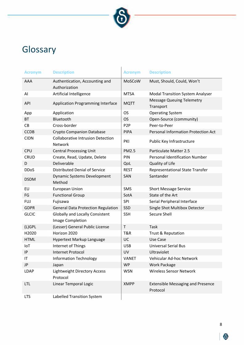
Glossary
Acronym Description Acronym Description
AAA Authentication, Accounting and
Authorization
MoSCoW Must, Should, Could, Won’t
AI Artificial Intelligence MTSA Modal Transition System Analyser
API Application Programming Interface MQTT Message Queuing Telemetry
Transport
App Application OS Operating System
BT Bluetooth OS Open-Source (community)
CB Cross-border P2P Peer-to-Peer
CCDB Crypto Companion Database PIPA Personal Information Protection Act
CIDN Collaborative Intrusion Detection
Network PKI Public Key Infrastructure
CPU Central Processing Unit PM2.5 Particulate Matter 2.5
CRUD Create, Read, Update, Delete PIN Personal Identification Number
D Deliverable QoL Quality of Life
DDoS Distributed Denial of Service REST Representational State Transfer
DSDM Dynamic Systems Development
Method
SAN Santander
EU European Union SMS Short Message Service
FG Functional Group SotA State of the Art
FUJ Fujisawa SPI Serial Peripheral Interface
GDPR General Data Protection Regulation SSD Single Shot Multibox Detector
GLCIC Globally and Locally Consistent
Image Completion
SSH Secure Shell
(L)GPL (Lesser) General Public License T Task
H2020 Horizon 2020 T&R Trust & Reputation
HTML Hypertext Markup Language UC Use Case
IoT Internet of Things USB Universal Serial Bus
IP Internet Protocol UV Ultraviolet
IT Information Technology VANET Vehicular Ad-hoc Network
JP Japan WP Work Package
LDAP Lightweight Directory Access
Protocol
WSN Wireless Sensor Network
LTL Linear Temporal Logic XMPP Extensible Messaging and Presence
Protocol
LTS Labelled Transition System

9
Executive Summary
This document is the deliverable ‘D3.2 M-Sec Requirements Analysis – final version’ which comprises the final
major outcome of the task ‘Task 3.1 – System level and User level Requirements analysis’. It contains an
extensive elicitation of requirements for the project to cover and an in-depth analysis on top of them. The
final list of the said requirements is available in Section 2, whereas the next sections provide the analysis
results extracted from this list.
The structure of this document follows exactly the one of the requirements management approach that was
followed for the completion of the activities of T3.1. In Section 1, the overall methodology followed is being
presented. Next, in Sections 2, 3, 4, 5, and 6, each step of the requirements management approach is being
presented, with the methodology and the results of each specific step being documented in detail. Finally,
Section 7 concludes the deliverable.
The document is accompanied by a spreadsheet which has been the main source for extracting all the statistics
and main lists of requirements (split into categories, groups, etc.), as well as the primary working file which
was used internally by the consortium to gather and extract details for each requirement. Some brief details
about the usage of the spreadsheet are provided in the Annex section of this document.
Regarding the differences between ‘D3.1 M-Sec Requirements Analysis – first version’ and ‘D3.2 M-Sec
Requirements Analysis – final version’:
In Section 1, the overall methodology followed within Task 3.1 is being revisited and presented in a more
structured and detailed manner. Although it still includes the steps identified in Y1, the section has been
updated so as to also include the Y2 activities, thus completing the requirements management lifecycle.
Section 2 presents briefly the background information provided in Sections 3 and 4 of D3.1, of course with
some changes to the description of the use cases and the project’s assets, aligned with the developments
that took place in Y2. The information in this section though is not one of the primary results of the task
and it is repeated (in more detail) in other deliverables from other WPs. As such, if the reader is accustomed
at a certain level to the specifics of M-Sec, they can skip this section.
Section 3 corresponds to Section 5 of D3.1 and lists the actual requirements of the project. However, since
some new requirements were added in Y2 and a new consolidation schema has been chosen, it is still
important for the reader to go through this section.
Sections 4 and 5 are brand new sections that present new requirements analysis steps introduced in Y2,
and as such they present results acquired only in this year and not in Y1.
Finally, the Annex and the corresponding requirements spreadsheet is something introduced only in the
second year of the project and includes all the acquired information extracted during the requirements
elicitation and analysis steps.
All in all, the deliverable is considered to have provided a valuable source of information and an easy-to-use
approach for taking design decisions and validating the results of M-Sec.

10
1. Introduction
1.1 Scope of the document
The current document is the deliverable ‘D3.2 M-Sec Requirements Analysis – final version’ which comprises
the final major outcome of the task ‘Task 3.1 – System level and User level Requirements analysis’. Task T3.1
is in charge of identifying system and use cases related requirements that reflect real citizen’s needs, and of
consolidating all of them in a way that facilitates the design of the overall M-Sec system. As such, this
deliverable contains an extensive elicitation of user and technical side requirements as well as a
comprehensive and in-depth analysis on top of them.
The primary audience of this document consists of the members of the consortium that participate in the
design and development of the components and modules of the M-Sec pilots as well as of the M-Sec core
system per se. Additionally, the document is of wider interest to stakeholders that are active in the domains
of Smart Cities, IoT, Security and Big Data, including researchers participating and contributing to H2020
projects under the aforementioned topics.
1.2 Overall methodology followed
The following figure gives an overview of the overall Requirements Management methodology devised and
followed in order to complete Task 3.1 successfully and provide valuable results for other Tasks. Requirements
Management consists of two phases: Requirements Elicitation and Requirements Analysis.
Figure 1—1: M-Sec Requirements Management methodology

11
The Requirements Elicitation phase comprises all the steps and activities required to acquire the requirements
list. It consists of the following primary steps:
Step 1 – Requirements Sources Identification: This step includes all the activities required to acquire all
the background information needed for the Requirements Extraction. These activities include the
identification of the main sources from which requirements can be extracted and the corresponding
background information related to these sources. Within the M-Sec scope, the background information is
provided by an analysis of the general scope and the objectives of the project, the Use Cases studied in its
context (and the related stakeholders) as well as the technical background of the consortium partners, the
technical details and capabilities of the assets they provide, as well as the corresponding SotA. The
methodology and the results of this step are presented in Section 2.
Section 2 – Requirements Extraction: This step includes all the activities required to acquire the actual
requirements list from the several sources identified in the previous step. It includes the selection of the
techniques, approaches and tools to be used, the actual elicitation and description of the requirements as
well as the corresponding documentation process. The methodology and the results (the requirements list)
of this step are presented in Section 3.
The Requirements Analysis phase comprises all the steps and activities required to process and analyse the
requirements extracted in the previous phase in such a way that valuable results and conclusions are
extracted. It consists of the following primary steps:
Step 3 – Requirements Consolidation: In this step, the requirements are grouped through various ways.
For example, requirements can be split into specific categories, types, groups and subgroups or be mapped
to specific Use Cases and stakeholders. The corresponding categorisation schema is used to define a
specific coding procedure so as to get a unique (and descriptive) identifier for each requirement. Although
this coding and part of the categorisation schema appear in Section 3 (to make easier the presentation of
the elicited requirements), the methodology and more results of this step are presented in Section 4.
Step 4 – Requirements Prioritisation & Scheduling: In this step, several parameters are taken into
consideration in order to prioritise the requirements, identify their criticality and recognise what
requirement may need extra attention at specific stages of the project, as M-Sec progresses. The
methodology and the results of this step are presented in Section 5.
Step 5 – Requirements Fulfilment: In this step, requirements are linked to specific functional groups (FGs)
and assets of the project, and a method to fulfil or face each requirement is offered. It is also in this step
that the regular monitoring of the progress towards the fulfilment of the requirements takes place. The
methodology and the results of this step are presented in Section 6.
The several activities described in the above steps take place in a roughly chronological order. During Y1, the
consortium focused on Phase 1 (Steps 1 and 2) and took its first steps towards Phase 2 (initial activities in Step
3). In Y2, the consortium focused on Phase 2 by completing (and reconsidering) Step 3 and introducing Steps
4 and 5. It should be noted though that previous steps were “revisited” again in Y2 so as to acquire new
requirements and updated information, based on the new developments in other areas of the project. In
addition, it is of interest that activities in later steps supported activities in previous ones. A characteristic
example is the categorisation activity, after the completion of which it became easier to study requirements
in groups and, as such, to avoid repeating requirements and to merge other ones.

12
The following figure presents an overview of the several stages (activities in chronological order) implemented
in T3.1 to complete the Requirements Management Lifecycle. The procedure is also presented roughly in the
[Version Control] tab of the accompanying D3.2 spreadsheet.
Figure 1—2: M-Sec Requirements Management lifecycle
To support all these activities, a spreadsheet was created during Y2. This deliverable is accompanied by the
latest version (as of M24) of the spreadsheet. The spreadsheet includes all the requirements and the
corresponding results of requirements analysis. Its various sections in the [Requirements] tab correspond to
the activities presented in detail in Sections 2.1, 3.1, 4.1, 5.1 and 6.1.
Although the outcome is a considerable amount of information which may seem hard to process manually
(5,600 fields), by sorting, filtering and hiding columns and lines it is possible to extract valuable consolidated
and structured information fairly easily. The results of such processes are shown in the “Results” Sections 4.2,
5.2, and 6.1. More information about the spreadsheet is also provided in the Annex of this document, whereas
some references also appear in the rest of the deliverable.

13
1.3 Relation to other WPs and Tasks
The following figure gives an overview of the relations of this deliverable and the corresponding Task (T3.1) to
other WPs, Tasks and deliverables. The figure is focused on T3.1, so not all relations between the rest of the
tasks are presented.
Figure 1—3: Relation of T3.1 and D3.2 to other WPs and Tasks
Task 3.1 receives input from WP2 and in particular from Tasks “T2.1 - Use cases description” and “Task 2.2 -
Pilots: definition, setup and citizens involvement” through the corresponding deliverables (D2.1 and D2.2).
More specifically, these deliverables provide in an holistic way an overview of the use cases description along
with particular details on their implementation within the pilots. To do so, D2.1 provides a full analysis of the
use cases covered in the M-Sec project. D2.2 then describes the different actors/stakeholders involved, the
functions and conditions that need to be offered, how, when and where the pilots will be set up, and the plan
for engaging and committing the participation of the citizens and the stakeholders. Also, T3.1 takes as input
from WP4 information about the capabilities and technical specifications of the available assets, information
that can be used to extract technical requirements (focused on assets constraints) but also ideas about the
fulfilment process of requirements.
At the same time, Task 3.1 is in alignment to “Task 3.3 - Risks & Security elements” and “Task 5.3 - GDPR
compliance”. These three tasks together are the baseline for all development, design and integration decisions
that have to be taken on a project level, always in line of course with the overall Architecture of the project.
Finally, regarding the exploitation of the output of Task 3.1, having as an aim the full definition and
consolidation of the M-Sec requirements, the Task provides its results to “Task 3.2 - Architecture” by
contributing to the overall design and specification of the M-Sec system. The outcomes of this deliverable will
be also used as input to “Task 2.4 - Overall system validation and evaluation”.

14
2. Step 1: Requirements Sources Identification
2.1 Methodology
The first step of Requirements Management, “Requirements Sources Identification” (Figure 1—1, 1st column),
starts with a definition of the M-Sec concept, including an overview of the use cases, use case diagrams and
the stakeholders involved so as to understand the context of the project and identify the various stakeholders.
These specific steps have been implemented within Task 2.1 and Task 2.2 and are reflected in the
corresponding deliverables.
As a next step (and based on the previous one), the analysis focused on requirements from potential end-
users of the M-Sec platform, including both corporate users and citizens. A variety of modalities was exploited
towards eliciting requirements, including review of the state-of-the-art services and direct contact with all
stakeholders that comprise the M-Sec value chain. Direct contact with stakeholders was pursued based on the
partners’ business networks, involving experts from the large industrial partners of the consortium.
In parallel with this step, the consortium partners gave an overview of the technologies involved in the project
and the perspective of using them in order to implement the M-Sec concept. Similar projects and background
from previous projects were also taken under consideration in order to present the state-of-the-art and the
previous achievements that can be used as a starting point.
The requirements elicitation process relies heavily on the involvement of the stakeholders in the whole value
chain that the project brings. It should be noted that the M-Sec consortium includes all necessary stakeholders
of the M-Sec value chain. In particular, the consortium includes smart city infrastructure providers, technology
providers as well as service providers and integrators (i.e. the technical partners from EU and JP side) and end
users as these recruited in WP5. This approach allows for a credible validation of the M-Sec concept, along
with different deployment configurations and services operations plans.
In order to extract the requirements from the use cases of the project a template was created and was filled
in by all UC related partners. The following subsections were included for each use case, focusing on
input/needs of potential end-users of the M-Sec platform, including corporate users and citizens:
Use Case description: This subsection presents briefly the main UC per se (what the “problem”/scenario
expected to be tackled is and what are its parameters). A brief presentation of this input is provided in
Section 2.2.
Stakeholders involved and specific needs and contributions: This subsection provides a list of the
stakeholders involved in the UC as well as their main needs that should be covered by the UC and the
project. It also describes the stakeholders’ direct or indirect contributions to the project. The input provided
here was used to map requirements to specific stakeholders, as it is mentioned in Section 4.
Requirements summary: More technical details about needs/contributions are given in this subsection
through a list of Scenario specific and another list of Security/Privacy specific requirements. Some of these
requirements are quantitative. This is the main output required and the results of it are included in the
requirements list in Section 3.

15
Similarly, a template was provided to all the technical partners of the consortium that enabled them to provide
an overview of the technologies involved in the project. In an attempt to identify dependencies between these
technologies as well as the candidate UCs that they support, and to identify more technical requirements
relevant to the project, the following subsections were included for each asset:
Technology asset description: This subsection includes a detailed description of the asset, as well as related
photographs/pictures and diagrams. In this deliverable, only a brief presentation of the assets is provided,
while a more extensive view is included in ‘D3.4 M-Sec Architecture: Functional and technical specifications
– final version’.
Relation to M-Sec: This subsection provides a small presentation of the relation of the technology asset to
the M-Sec project concept. In some cases, based on the input provided through the UCs description as well
as the corresponding deliverables of WP2, the use cases needs that this asset can cover are presented in
more detail. This input was used to map specific assets to requirements, as it is described in Section 5.
Requirements summary: In this subsection the various functionalities that should be covered by the asset
and its limitations (e.g. handling X amount of data per day) are presented. This is the main output required
and the results of it are included in the requirements list in Section 3.
The procedure of filling in these templates took place in the beginning of Y1 and was repeated in Y2. That way,
it became possible to take under consideration the updated version of the UCs, the assets used in the project
and the new requirements that were identified.
Since the main focus of this deliverable is the presentation of the requirements per se and the results of the
requirements analysis, the UCs and the assets will be presented only briefly in Sections 2.2 and 2.3.
The input provided about the stakeholders is included in the results presented in Section 4 (and the
corresponding section of the accompanying spreadsheet to this deliverable). Finally, the input regarding the
relation of assets to M-Sec is not presented on this document at the assets description section but is included
in the results of Section 5 (and the corresponding section of the accompanying spreadsheet to this
deliverable).
More details on the UCs and stakeholders can be found in D2.1 and an updated view will be provided in ‘D2.3
M-Sec pilot definition, setup and citizen involvement report’ in M24. More details on the assets links are
provided in ‘D3.4 M-Sec Architecture: Functional and technical specifications – final version’. Here, they will
be presented briefly.

16
2.2 Overview of the Use Cases
UC1 – Secured IoT Devices to enrich strolls across Smart City parks (SAN-UC1)
Governments around the world are devoting significant effort and resources to the management of the
environment. Likewise, the city of Santander is also involved in this activity and is trying to carry out an
effective policy for environmental management through the signing of agreements that aid improvements in
air quality and QoL (Quality of Life) for its citizens. A key element in undertaking this task is the noise, CO2 and
temperature level measurements.
Currently, noise measurements are taken by the Engineering Department of the Council in a timely manner;
generally, in response to complaints, abnormal operation of some service, etc. However, it is an important
issue for all cities to provide a real-time heat map and periodic reports of noise pollution levels which allows
monitoring of the city. Furthermore, the evaluation of CO2 levels in areas closer to nearby housing areas and
how it compares to the levels registered in the park centre are of high interest to the Municipal Services.
In addition, another interesting parameter from an environmental perspective is temperature monitoring at
different points across the city. Indicatively, its study could provide measurements useful for research on the
interaction of the traffic and pollutants with the environment and global warming.
In this sense, it may also be of high interest for both citizens and the City Council to know at every time the
‘occupancy’ levels of certain spots in the city, such as the different spots the Las Llamas Park is divided in
(playground, artificial lake, sport trails, etc.). If the corresponding heat map suggests that there are a lot of
people in a specific area, users could pick other spots and diminish the traffic and pollutants, while the
Municipality will be able to sketch specific initiatives based on these data.
UC2 – Home Monitoring & Wellbeing Tele-assistance for active and independent ageing people (SAN-UC2)
This UC, carried out in Santander city, intends to face the main challenge of the rapid increase of elderly
population during the past years caused by the increase of life expectancy due to medical, social and economic
advances. Ageing people may feel isolated due to the lack of close family ties or the result of living alone.
Additionally, many ageing citizens live with a constant fear of accidents at home (e.g. falling down) or facing
health-issues without being detected or helped by others for a long time. Therefore, the consortium aims to
provide a solution that already covers some issues related to wellbeing and safety at home.
The pilot of this UC is going to focus on home activity monitoring through the use of sensors such as presence
sensors, bed occupancy sensors, window/door open sensors and smart plugs. This pilot has the aim to
digitalise some of the current analogic-based, tele-assistance services provided by the Social Services
department of the Santander City Council through a third-party operator.
The platform provides the following features: Connected Care Portal Platform user Management; Live
Dashboard (alarms activated, latest activity); Patient/User Management (user data, device assignment, alarm
assignment and custom setting, history data); Device Management (device info, connectivity & battery
feedback); Alerts configuration (generic setting based on device/sensor type. Single Alert. Combined Alert).

17
UC3 – Secure and Trustworthy Mobile Sensing Platform (FUJ-UC3)
This use case provides a client application that allows urban environment monitoring entities (for example
local governments) to visualise spatially and temporarily dense environmental data. Using the application, the
entities are enabled to better serve their citizens with sophisticated environment monitoring. In this scenario,
an automotive sensing platform is used to generate real-time environmental sensor data streams from all over
the city of Fujisawa leveraging a hundred mobile sensing trucks. Additionally, the trucks are equipped with
cameras that can acquire data related to garbage counting/collection.
The environmental sensors (temperature and humidity, PM2.5, acceleration sensor, etc.) in the sensor boxes
installed in the garbage trucks that run all over the city every day, and the images of in-vehicle cameras will
be the input data to Flexible analytics app via SOXFire, an advanced sensor platform based on Publish /
Subscribe messaging patern. The pilot will be enriched with M-Sec secure and reliable assets and an analytics
system with deep learning processing that can operate in edge computing processing environment. This use
case illustrates how the M-Sec platform secures such a mobile sensing platform.
UC4 – Secure Affective Participatory Sensing of City Events (CB-UC4)
This use case explores the possibility of secure sharing on citizen’s affective information and information on
the city, by using “SmileCityReport” application on the M-Sec platform. This use case is related to topics such
as mobile participatory sensing, edge-(mobile-)side computation for privacy protection, secure data sharing
of sensed information, etc. Unlike UCs 1, 2 and 3, this use case will not focus on IoT devices for smart homes
or cities, but will rely on mobile phones and devices used by citizens. The pilot of the UC will first take place in
Fujisawa and next will be extended to Santander, thus resulting in a cross-border use case.
UC5 – A marketplace of IoT data for effective decision making (CB-UC5)
The aim of this use case is to construct a marketplace between EU and Japan to distribute data by ensuring
Confidentiality, Integrity, Availability, and Privacy of data following GDPR/PIPA regulations, so that people or
organisations in EU and Japan can utilise the data more effectively.
Recently, business opportunities are expected in various situations around the world. Not only the IT industry
and the financial industry (that have traditionally used data), but also other businesses are trying to utilise
data for many cases such as planning business strategies, as the performance of various devices and sensors
is improving due to the evolution of IT technologies. In addition, it is logical to expect that even citizens buy
and sell data as they recognise the value of the data for improving their lives and convenience. In such
circumstances, data distribution in both domestic and cross-border areas needs to take place safely and
smoothly to make the data effective enough to contribute in “building” the smart cities.
Along with the development of the Internet in recent years, since cyber-attacks are becoming increasingly
complicated and sophisticated, provision of a secure data distribution method between countries is an
essential task for smart cities. The aim of this use case is to construct a marketplace where data integrity is
present or tamperproof data can be securely distributed.

18
2.3 Overview of the partners’ Assets
Figure 2—1 provides an overall presentation of the partners’ assets, including their corresponding Functional
Group (FG), Layer and Task. Similarly, Figure 2—2 shows the mapping the assets to specific UCs. The assets
are presented in the next subsections under their corresponding Functional Group. More details about FGs
are provided in ‘D3.4 M-Sec Architecture: Functional and technical specifications – final version’. The tables
are available in the [Assets & UCs] tab of the accompanying spreadsheet to this deliverable.
Figure 2—1: Overview of the partners’ Assets – Relation to FGs and Layers
Figure 2—2: Overview of the partners’ Assets – Relation to UCs
Asset Partner Functional Group Layer Primary Task
SmileCityReport (App) KEIO Applications Application Task 2.3
UC3 APP KEIO Applications Application Task 2.3
Park Guide TST Applications Application Task 2.3
Worldline Connected Care Assistance WLI Applications Application Task 2.3
Node-RED WLI Development & Designing Tools Middleware Task 2.3
Honeypot (IoTPOT) YNU Development & Security Designing Tools IoT Task 4.1
Modal Transition System Analyser (MTSA) WU Development & Security Designing Tools Application Task 4.4
SAT & DMSS NII Development & Security Designing Tools Application Task 4.4
Deep Counter (Garbage Identification AI) KEIO Devices IoT Task 2.3
Secure Mobile Sensing Platform KEIO Devices IoT Task 2.3
TST IoT crowd-counting devices TST Devices IoT Task 2.3
TST IoT environmental devices TST Devices IoT Task 2.3
Caburn Home Monitoring Devices WLI Devices IoT Task 2.3
Secured components for devices and gateways CEA Devices Security IoT Task 4.1
Intrusion Detection System (IDS) YNU Devices Security IoT Task 4.1
Monitoring & Visualization Tool YNU Devices Security Cloud Task 4.1
Security Management Tool CEA End-to-End Security Cross-Layer Task 4.5
Mobile Wallet WLI IoT Data Marketplace Application Task 2.3
IoT Marketplace ICCS IoT Data Marketplace Application Task 4.3
Ganonymizer KEIO Privacy Management Tools IoT Task 4.1
Crypto Companion Database WLI Secure & Trusted Storage Cloud Task 4.2
Quorum Blockchain/Blockchain middleware ICCS Secure & Trusted Storage Middleware Task 4.3
T&R Model engine/tool ICCS Secure & Trusted Storage Middleware Task 4.3
Eclipse sensiNact platform (and Studio) CEA Secure City Data Access Middleware Task 4.2
Secure SOXFire KEIO Secure City Data Access Middleware Task 4.2
SmileCityReport (Server) KEIO Storage Application Task 2.3
Asset Partner Part of… UC1 UC2 UC3 UC4 UC5 Global
SmileCityReport (App) KEIO Pilot System no no no yes yes no
UC3 APP KEIO Pilot System no no yes no no no
Park Guide TST Pilot System yes no no no no no
Worldline Connected Care Assistance WLI Pilot System no yes no no no no
Node-RED WLI Pilot System yes yes yes yes yes yes
Honeypot (IoTPOT) YNU Pilot System no no yes no no no
Modal Transition System Analyser (MTSA) WU Core System yes yes no no no no
SAT & DMSS NII Core System no no yes no no no
Deep Counter (Garbage Identification AI) KEIO Pilot System no no yes no yes no
Secure Mobile Sensing Platform KEIO Pilot System no no yes no yes no
TST IoT crowd-counting devices TST Pilot System yes no no no yes no
TST IoT environmental devices TST Pilot System yes no no no no no
Caburn Home Monitoring Devices WLI Pilot System no yes no no yes no
Secured components for devices and gateways CEA Core System yes no no no no no
Intrusion Detection System (IDS) YNU Core System no no yes no no no
Monitoring & Visualization Tool YNU Core System no no yes no no no
Security Management Tool CEA Core System yes yes yes yes yes yes
Mobile Wallet WLI Pilot System no no no yes yes no
IoT Marketplace ICCS Core System yes no yes yes yes no
Ganonymizer KEIO Core System no no yes yes yes no
Crypto Companion Database WLI Core System yes yes yes yes yes yes
Quorum Blockchain/Blockchain middleware ICCS Core System yes yes yes yes yes yes
T&R Model engine/tool ICCS Core System yes no no yes yes no
Eclipse sensiNact platform (and Studio) CEA Core System yes yes no no no no
Secure SOXFire KEIO Core System no no yes no no no
SmileCityReport (Server) KEIO Pilot System no no no yes yes no

19
Devices
Secure Mobile Sensing Platform
The mobile sensing platform is capable of sensing acceleration, angular velocity, humidity, temperature,
atmospheric pressure, PM2.5, UV-A, and location. It consists of about 70 garbage collection trucks in Fujisawa,
on each of which a sensor box is mounted. Among them, PM2.5, UV-A, temperature, humidity, and
atmospheric pressure are valuable for citizens to monitor the environment, while acceleration and angular
velocity are valuable for the local government to monitor road surface. In addition to these sensors, all the
trucks have two cameras, one in its front and the other in their rear. These cameras can be used to visually
monitor road surfaces and the amount of collected garbage. The trucks cover the whole city; they visit all the
houses in the city (since in this city, garbage collection is operated on a house-by-house basis, instead of a
garbage collection stations one). Sensor data are transmitted 100 times/second (max) using XMPP to acquire
temporarily dense sensor data. The data streams are handled at SOXFire (described later on) server based on
a publish/subscribe policy. A sensor on a truck publishes the sensor data stream to a virtual sensor node
configured in the server, and the stream is routed to entities (e.g. applications and services) that have
subscribed to this virtual sensor node. This platform is a distributed system consisting of edge computers
(sensors) and a cloud system (SOXFire server).
Deep Counter
The Deep Counter automatically counts the amount of garbage from camera images attached to the garbage
truck using Deep Learning. Deep Counter makes it possible to specifically quantify and analyse where and how
much garbage is discharged. The Deep Counter uses Deep Learning to automatically recognise and count
garbage bags from camera images attached to garbage trucks. At this time, deep learning is being performed
at a high speed to enable edge processing with the system mounted on the garbage truck. Being able to
perform intelligent processing such as Deep Learning on the edge side is not only important for M-Sec but also
generally in terms of security, as in this case no extra data are required to be sent to the cloud. It is very
effective in terms of security by processing the advanced analysis processing on the edge side and returning
only the minimum necessary data to the cloud without unnecessarily raising the security information
contained in the image to the cloud.
TST IoT environmental measurements devices
This IoT device designed and developed within M-Sec framework, takes advantage of the extensive company’s
(TST) background in designing and developing custom IoT devices. TST has a vast experience carrying out
specific projects that require the design and development of those custom IoT devices that comprise of
different sensors and make use of diverse communication technologies such as ZigBee, Wi-Fi, NB-IoT or BLE.
The available modules contain a series of sensors, such as temperature, humidly, noise level and CO2. In order
to provide data generated by these IoT devices, TST uses the MQTT protocol in them, which simplifies the
collection of sensor data, the publication of the different values obtained and the remote configuration of
nodes.

20
TST IoT crowd counting device
IoT devices will be specifically created to generate heat maps of specific city spots in Santander, selected in
agreement with the City Council representatives. These IoT devices are capable of detecting BT/Wi-Fi signal
from cell phones and sketching a map related to the number of people present at a certain time in a designated
spot. Upon discussion among partners in the consortium and getting to know the real needs posed by
Municipality services, M-Sec will consider the IoT devices as a crowd-counter. Originally, they will be located
in designated spots within the Las Llamas Park, one of the most modern and iconic Santander Parks, close to
some city beaches and the University of Cantabria. However, it will be also useful in other areas that are
crowded during summertime due to various activities. So, the IoT device will be mobile to be put into those
diverse spots at different times. In order to provide data generated by these IoT devices, the MQTT protocol
is used in them, something that simplifies the collection of sensor data, the publication of the different values
obtained and the remote configuration of nodes.
Caburn Home Monitoring Devices
From all devices that Caburn has in its catalogue, M-Sec will use1:
Squid.link Gateway: The Squid.link Gateway is a modular platform for flexible Home Area Network. It
connects wireless devices through a communication protocol and reports data back to the user’s computer
or smartphone. The Squid.link Gateway is configurable and an extremely flexible solution for connecting
networks based on different technologies.
Door/Window Opening Sensor: The Door/Window Sensor detects and reports the opening and closing of
doors and windows. Easily installed on any door or window, the sensors trigger a signal when parted,
notifying the user when a room is entered. The Window Sensor also features a built-in temperature
measuring functionality that measures changes in room temperature, down to a 0.1°C interval. Readings
from the sensor can be sent via a home automation system through SMS, e-mail, or web. The increased
awareness of temperature and daily power consumption can help your customer decrease their heating
costs.
Motion Sensor Mini: The wireless Motion Sensor Mini is a compact motion sensor. The product includes
an occupancy sensor, a light sensor, an alarm sensor, a temperature sensor, and a tamper switch. The
provided mounting screws can be used to mount the Motion Sensor Mini in the corner or flat on the wall
or ceiling. Alternatively, the included stand can be used to place the Motion Sensor Mini on a table or shelf.
Smart Plug Mini: The Smart Plug Mini is an intelligent remotely controlled adapter that monitors the power
consumption and enables the user to control electrical equipment by switching it on or off remotely via
ZigBee. The Smart Plug Mini is easy to use since it requires no installation. The user just has to put it into
an electrical outlet and then plug in the desired electrical device.
1 Information extracted from : https://caburnsolutions.com/product-systems/

21
Applications
Park Guide
Park Guide is intended to be the application Use Case 1 employs through handheld devices by registered users
to interact with the physical deployment in Las Llamas Park. This web application will receive periodic
information related to the measurements registered by the IoT devices and present it in a way users find easy
to grasp. The application will offer users several sections for them to not only check quickly the most recent
values but also see their evolution during the last few days. Some graphs will be generated to facilitate the
understanding of what is happening in the Park and even help municipal services to take action whenever they
consider it necessary. Some QR codes will be scattered in strategic points of the park for users to scan them
and access specific sections in the web where they can read about the specifics of that area and even get to
know not so famous aspects of it. In further stages, the application will include the possibility of playing an
interactive game among users, inviting them to visit all the areas in the park marked with those QR codes.
Worldline Connected Care Assistance
Worldline Connected Assistance is a networked care platform for patients and their caregivers (professional
and informal ones) facilitating remote health monitoring and management to enhance independent living and
a better quality of care at home. This asset provides an IoT-centred business solution enabling patients’ health
data self-management through the use of wearables and medical devices. Once captured, health data are
securely transmitted to health providers for analysis and monitoring.
SmileCityReport
SmileCityReport is an affective participatory sensing system where participating users (including local citizens
and visitors) can share photos and associate affective information securely in protected group areas. The
SmileCityReport system is a combination of the server side (SmileCityReport server) and the client smartphone
application (SmileCityReport app.). At its simplest sense, it is a photo-sharing social network service. The users
can invite and join “themes” in which a specific topic about photo reports will be set. Examples of the themes
are “Nice flowers in your neighbourhood” and “Dangerous traffic intersection in your local area”. Once the
theme is created by a user, other invited users can post their “entries” to the theme. Each theme is taking a
role of data protection domain. Thus, the posted entries in a theme can only be visible to other users joining
in the theme. When a user creates an entry to the theme, the client app will use two cameras (in-cam and out-
cam) of the user’s smartphone simultaneously. When the user takes a photo of a scene/event in the city (e.g.
a beautiful sunset), a photo of the reporting user will be also taken by using the in-cam. Furthermore, some
affective status (e.g. smile degree) will be extracted from the in-cam photo. The combined data (2 photos and
associated affective status data) will be posted as “an entry” to the theme. The users can browse the other
theme members’ entries (out-cam photo, in-cam photo, and the reporter’s affective status). When the user
browses them, the browsing user’s affective information will be taken by the in-cam of the smartphone and
will be shared back to the reporting users as “smile like”.

22
Devices Security
Secured components for devices and gateways
Secure components are a common countermeasure for preventing hardware attacks from connected
products. These components store sensitive information and make sensitive operations in an area protected
from direct attacks (such as side-channel or fault injections). CEA has developed a toolbox for integrating
various forms of such secure components into new or existing platforms. The goal is to provide the following
functions on IoT systems: storing sensitive information such as private SSH keys, disk decryption key,
passwords, PIN numbers and others; performing sensitive operation in a more secured way, such as hash
functions or random number generation; verifying the integrity of a system by monitoring the bootchain and
state of the device. The toolbox associated with these components consists of tools for provisioning
components for certificate initialisation and the possible association with a PKI, the initialisation of
standardised interfaces such as PKCS112 as well as tools for the verification of integrity when booting and
attaching removable media to platform instances.
Intrusion Detection System (IDS)
Due to the explosive growth of Internet of Things (IoT), billions of IoT devices have surfaced in all aspects of
life. This has provided a harvesting ground for “bad guys” to attack and compromise IoT devices to be used as
Botnets for further attacks. Use Case 3 defines a common IoT scenario that can be expected in a hyper-
connected smart city, where information from sensors or IoT devices needs to be delivered without
compromising the triads of information security, i.e. confidentiality, integrity, and availability. Intrusion
Detection System is a perimeter security solution that examines full packets or a system and analyses it to
identify abnormal patterns (anomalies) or specific patterns (signatures). On detecting a match, it can be made
to either just function as a detector and report to the security center by logging the event or it can also be
programmed to drop the pattern/signature matching packets in order to block malicious traffic from entering
the network. This way an IDS can provide detection and prevention capability to the IoT devices layer and help
in securing it from malicious attackers.
Monitoring & Visualisation tool
In order to stay vigilant and monitor threats to the IoT devices layer from anywhere in the cloud, an analysis
tool is required that can translate the data into easy-to-understand graphical information. Threat monitoring
visualisation tool is a software-based solution that collects and examines activity from the IoT layer or agents
embedded in the IoT gateway devices. This tool not only helps with the security health checks by providing
insight into how the security is being maintained at IoT gateways, but also helps in further analysis of devices
under attack, thereby, providing 24/7 security threat monitoring and alerts. This software solution consists of
four modules: Data Collection Agents; an Aggregator Module; a Data Analysis Module; and a Visual Graphics
Module. The software is integrated with secured mobile sensing platform and the embedded agents upload
the IDS logs to the visualisation tool in the cloud. The tool converts the data into easy to understand
information and graphs. This way security health check can be monitored remotely.
2 https://www.oasis-open.org/standards#pkcs11-base-v2.40

23
Secure City Data Access
Eclipse sensiNact platform and Studio
The Eclipse sensiNact project consists of a software platform enabling the collection, processing and
redistribution of any data relevant to improving the quality of life of urban citizens, and programming of
interfaces allowing different modes of access to data (on-demand, periodic, historic, etc.) and application
development and deployment to easily and rapidly build innovative applications on top of the platform. At the
heart of sensiNact lies its service-oriented approach in which IoT devices expose their functionalities in terms
of services (temperature service, presence detection service, air quality monitoring service, alarm service,
etc.). Each service then exposes one or several resources such as sensor data or actions. Thus, building
applications becomes a matter of composing sensing services with actuation services. Loose coupling between
the devices and the services they implement makes the composition of services more dynamic and adaptable
to the changing context, not only in the software environment (increasing CPU or memory usage, low battery,
reducing quality of measures, etc.) but also in the physical environment (replacing sensors, changing
localization, etc.).
Secure SOXFire
Sensor over XMPP (SOX) is a distributed platform that enables scalable collection and dissemination of real
world data with standardised metadata using a publish/subscribe method. The technology is open at the
website of KEIO and it has been in operation by KEIO for years. SOX can handle heterogeneous sensor data
streams. It has also been clarified by research from KEIO that a SOX server can handle at least 10,000 sensor
data streams concurrently. Opposing to the sensing side is the applications’ side where a number of services
and applications consume those differing sensor data streams. Considering the existence of data stream
producers and consumers between which connections are established in unpredictable and dynamic timings,
the platform needs to lower mutual dependency between them. To do so, SOX is based on a publish/subscribe
mechanism. The sensors publish data streams towards corresponding virtual sensor nodes in a SOX server,
while the applications subscribe to virtual sensor nodes relevant to their purpose. Publishers and subscribers
are indirectly connected via SOX while staying mutually independent.
Secure & Trusted Storage
Crypto Companion Database (CCDB)
The CCDB is a system that will encrypt the data with an asymmetric public/private key pair. The data can only
be accessed by the owner who has to be authenticated, and the authorised operators allowed by the owner.
With this database insertion, deletion and consultation of the information will be possible. The modification
process will be a bit more complex as the hash that holds the link between the blockchain and the database
will change if the information changes, so if a modification is needed it will be done by deleting the old
information and inserting the new one. Each application in the ecosystem can have its own crypto companion
database; therefore data will always be distributed. In order to make it accessible and replicated if need be,
the key pair can be replicated on any system by providing a 24-word mnemonic. To reduce the amount of data
held by a single database, the location of specific information can be stated in the blockchain transaction. The
components used to create the CCDB are the following: Crypto Module; Companion DB Module. The evolution
of the Companion DB Module with the Crypto Module makes a secured database, as the data will be encrypted
24
by an asymmetric key pair. The Crypto Module will be used independently on any type of database (currently
only supports MongoDB3) and in any software because it provides an API to encrypt/decrypt data. The API of
this module is designed as a private API with no access to the internet, so it does not provide any security. The
Companion DB Module has a public API that can be used to save, delete and query data. It also provides an
authentication layer in order to secure the users that access the data. This module also provides an
authorisation layer in order to know if the owner of the data allows an operator or external user to see it.
Quorum Blockchain & Blockchain Middleware
The main technical asset used as a blockchain implementation in M-Sec is the Quorum Platform4. Quorum
supports private transactions within a permission group of known participants. It is an open source platform,
GPL/LGPL licensed just like Ethereum, supported by a growing community of users and developers. Since it is
designed to develop and evolve alongside Ethereum, it is able to incorporate the majority of Ethereum updates
quickly and seamlessly. It is actually a fork of go-ethereum5 and it is updated in line with go-ethereum releases.
Some features of Quorum over go-ethereum, important for the M-Sec project are: Privacy; Alternative
Consensus Mechanisms; Permissioned Network; Higher performance. Quorum consists of the following
components: Quorum Node:; Constellation/Tessera - Transaction Manager; Constellation/Tessera – Enclave.
Trust & Reputation Model/Engine
Trust and Reputation (T&R) models have been proposed by many researches as an innovative solution for
guaranteeing a minimum level of security between two entities of a distributed system that want to have a
transaction or interaction. T&R management is a very useful and powerful tool in environments where a lack
of previous knowledge about the system can lead participants to undesired situations, specifically in virtual
communities where users do not know each other at all or, at least, do not know everyone. The T&R Model
utilised in M-Sec will follow four steps: 1. Collecting information about a certain participant in the community
by asking other users their opinions or recommendations about that peer; 2. Aggregating all the received
information properly and somehow computing a score for every peer in the network; 3. Selecting the most
trustworthy or reputable entity in the community providing a certain service and effectively having an
interaction with it, assessing posteriori the satisfaction of the user with the received service; 4. Punishing or
rewarding according to the satisfaction obtained, adjusting consequently the global trust (or reputation)
deposited in the selected service provider. The T&R engine will be used on top of the Blockchain Middleware
Services and the IoT Marketplace. Such an engine would enhance the security mechanisms of M-Sec and make
it possible to evaluate the actual content being shared through the Blockchain and the Marketplace, thus
ensuring the trustworthiness of the several actors participating in the exchange or sharing of information, data
and services.
3 https://www.mongodb.com/ 4 https://www.jpmorgan.com/global/Quorum 5 https://github.com/ethereum/go-ethereum

25
IoT Data Marketplace
IoT Marketplace
One of the main goals of M-Sec is to create decentralised IoT ecosystems and validate their viability and
sustainability. To this direction, we define and implement a novel marketplace where smart objects can
exchange information and services through the use of virtual currencies allowing real-time matching of supply
and demand, enabling the creation of liquid markets with profitable business models of the IoT stakeholders.
Market participants, from IoT devices to humans using mobile applications are able to exchange data and
value through the M-Sec blockchain implementation. The owner of a sensor/data source who wishes to make
their data available for purchase or exchange can register to the dedicated created smart contract providing
information about the type of the data, their frequency, the price, the location etc. Then, a user of the M-Sec
Platform who acts here as a potential buyer using our developed front-end can see all the available sensors
and their data. Upon finding some interesting data they can retrieve additional detailed descriptions about
them and then buy the data of interest using M-Sec Tokens, which is a cryptocurrency in the form of a smart
contract running in on blockchain presented in previous section. The deployed smart contracts communicate
with each other to verify the sufficient funds of the buyer and complete the purchase by transferring funds
from the balance of the buyer to the one of the data owner. The developed Node-RED (see next subsection)
flows also assist in this process connecting the different components of the system.
Mobile Wallet
In order to allow content consumers to buy access to media produced by content creators in a participatory
way (without excluding but also without needing the media industry and their classic distribution channels),
Mobile Wallet enables users to manage directly their transactions and get access to the content within the
Blockchain. The project has been built on Angular and updated to the latest version of Angular 96, and uses
Cordova7 to generate native apps for iOS and Android platforms. HTML5 has been used for the front end. The
application manages the entitlement that the user has with respect to content and cryptocurrency. We have
taken advantage of the Truffle8 development framework for the Smart Contracts used by the application,
allowing us to build and deploy the SC ecosystem in Blockchain. So, Smart Contracts have been used and the
app is ready to use either Ethereum ether or an ad-hoc currency. The app works without needing to store the
user’s private keys in any other system, thus avoiding unlicensed transactions.
Development & (Security) Designing Tools
Node-RED
Node-RED is a flow-based development tool for visual programming developed originally by IBM for wiring
together hardware devices, APIs and online services as part of the IoT. It provides a browser-based editor that
makes it easy to wire together flows using the wide range of nodes in the palette that can be deployed to its
runtime in a single-click. JavaScript functions can be created within the editor using a rich text editor. A built-
6 https://angular.io/guide/releases and https://angular.io/guide/updating-to-version-9 7 https://cordova.apache.org/docs/en/3.0.0/guide/overview/index.html 8 https://truffleframework.com/truffle

26
in library allows you to save useful functions, templates or flows for re-use. The light-weight runtime is built
on Node.js, taking full advantage of its event-driven, non-blocking model. This makes it ideal to run at the edge
of the network on low-cost hardware such as the Raspberry Pi as well as in the cloud. It is also able to cross-
compile in Arduino. With over 225,000 modules in Node's package repository, it is easy to extend the range
of palette nodes to add new capabilities. The flows created in Node-RED are stored using JSON which can be
easily imported and exported for sharing with others. An online flow library allows you to share your best
flows with the world.
Honeypot (IoTPOT)
Due to the rapid growth of various devices capable of communicating through the internet, the playfield for
attacking such devices has also exponentially grown. The “Mirai” malware attack (2016)9 using compromised
IoT devices has shown the world how vulnerable IoT devices are, and how malicious intent can be used to
disrupt businesses of large enterprises on the Internet. The security professionals use a computer system that
analyses various attack patterns (signatures) by attracting malicious entities to attack devices placed in an
isolated environment. Such a computer system is called “Honeypot”. By examining the attack methods, we
can come up with appropriate detection and protection mechanisms. In order to understand various attack
vectors and malicious codes, an IoT asset called “Honeypot (IoTPOT)” will be utilised. Its key purpose will be
as follows: Obtaining knowledge on the attack vectors of IoT devices (such as IP cameras, network drives, Wi-
Fi, sensors, etc.) through observation and analysis of various types of attacks from internet; Using this
knowledge to protect the IoT devices; Enabling Intrusion Detection System (IDS) to detect, report and prevent
attacks.
Security Analysis Tools & Development Method for a Secure Service (SAT & DMSS)
It is crucial for secure software development to use various types of security knowledge. As such, a security
requirements modeling support system (Security Analysis Tool) is provided, for a misuse case diagram that
enables the association of security knowledge with elements that constitute the diagram. The functions
provided by the Security Analysis Tool are the following: drawing diagrams; associating security knowledge
with elements of a diagram; browsing security knowledge in the knowledge base; reviewing function, and;
artifact management.
Modal Transition System Analyser (MTSA)
A specification is typically constructed manually by engineers and thus bugs are frequently injected by human
errors. Bugs in a specification cause reworking software development entirely and consume huge costs. These
bugs need to be eliminated in early phase of the development process to mitigate the risks. Modal Transition
System Analyser (MTSA) is a development tool for synthesising behaviour specification for reactive systems
with formal guarantee. MTSA synthesises a behaviour specification of a system from an environment model
and functional requirements. A synthesised behaviour specification is ensured to satisfy the given functional
requirements under the given environment model. MTSA reduces engineers’ effort to construct “correct”
behaviour specification by avoiding a number of trials-and-errors in construction and verification of
specification. More specifically, in MTSA, an environment model (representing assumptions on the reactivity
9 https://www.theguardian.com/technology/2016/oct/26/ddos-attack-dyn-mirai-botnet

27
of an environment) is described in the form of a labelled transition system (LTS). Functional requirements,
representing expected properties (such as safety or liveness), are specified in the form of linear temporal logic
(LTL) over events used in the LTS-based environment model. MTSA synthesises a behaviour specification in
the form of LTS which is theoretically guaranteed to satisfy the LTL properties on the LTS-based environment
model. MTSA is developed by Buenos Aires University and is publicly available as an open-source tool. The
MTSA tool provides a model editor, model viewer, model animator, and enactment framework, in addition to
the synthesis engine, developed as Java application. Engineers can use model editors and viewers to describe
an environment model and LTL properties, and test them by using model animator. A synthesised model can
be executed with enactment framework connecting the model and underlying implementation.
End-to-End Security & Privacy Management Tools
Security Management Tool
The security Manager is a set of centralised security functions that are necessary to ensure end-to-end
security, privacy and therefore digital trust. It is designed to support several security functionalities aggregated
in a single backend using the LDAP standard. In terms of M-Sec implementation, this security manager is
planned to be integrated into the project as follows: - Within IoT devices in T4.1 for provisioning devices with
initial manufacturer credential for firmware authentication. - In T4.2 between IoT devices and the cloud for
communication authentication and encryption. This is most likely an encrypted channel between IoT devices
and M-Sec middleware such as SOXFire and sensiNact. - In T4.3 to provide marketplace authentication and
authentication coordination between SOXFire/sensiNact and the blockchain implementation - In applications
within T4.4 in order to authenticate end-users in the system. The central element for the security manager is
a directory service containing all information to manage security services for clients, such services known as
AAA for Authentication, Accounting and Authorization. In the implementation form, we use an LDAP directory
as it is commonly accepted as a free and open standard from the IETF10. Public key infrastructure is also an
essential component in modern communication patterns enabling asymmetric cryptography between
untrusted parties. A public key infrastructure enables to bound public keys to identities (such as people or
devices). It is usually managed by an authority associated with many roles such as validation authority,
registering authority, etc. The dogtag PKI solution11 is used, which has native capabilities to use LDAP.
GANonymizer
In situations where video data are used in various IoT applications in smart cities, personal information is often
a problem. GANonymizer is a technology that automatically deletes personal information contained in such
videos using AI technology. GANonymizer consists of two parts of neural networks. In order to detect the
target objects from the input image, which might violate the privacy, we adopt the deep neural networks:
Single Shot Multibox Detector (SSD). And in order to generate a more natural image, Globally and Locally
Consistent Image Completion (GLCIC) is adopted, one of the most successful models in image completion. By
using GANonymizer, the background image can be automatically filled as if there were no such object, instead
of a general mosaic method.
10 https://www.ietf.org/ 11 https://www.dogtagpki.org/wiki/PKI_Main_Page

28
3. Step 2: Requirements Extraction
3.1 Methodology
The Requirements Extraction Step (2nd column in Figure 1—1) supports the definition of the desired
functionality of the M-Sec system given from the perspectives of the functional components and the non-
functional attributes that the final system has to expose.
The requirements are gathered and consolidated into one list, and are grouped and coded accordingly in order
to comprise the reference for the design, implementation and validation phases of the project. These results
are presented in the next section. In order to make the presentation of the requirements list easier, their Y2
Code and their Category and Group are provided, even though the Requirements Coding and Requirements
Categorisation processes are part of Step 3 – Requirements Consolidation (see Section 4).
In the figure below, an indicative view of the requirements list is provided, as it appears in the accompanying
spreadsheet to this deliverable.
Figure 3—1: A screenshot with an indicative view of the M-Sec Requirements analysis spreadsheet
The Requirements Extraction Step consists of the Requirements Identification, the Requirements Unification,
the Requirements Description, the Requirements Documentation and the Requirements Sources processes,
all presented in the corresponding sections of the spreadsheet and presented in detail below.
Requirements Identification: After the initial aggregation of the “raw” requirements (as given documented
by the consortium partners), a first level of processing them took place. A few requirements were removed
due to becoming obsolete or being considered out of scope (less than 10), or due to not being identified as
actual possible solutions to requirements rather than constraints or requirements per se.
Requirements Unification: Quite a few requirements were also merged/unified after being identified as
(almost) identical. For requirements already available in Y1 and merged during Y2, the Y1 Code is provided in
the corresponding column of the spreadsheet of all requirements that were merged together. For
requirements identified in Y2 and merged into others, a separate code has not been provided (however, all
Details
# Y2 Code Y1 CodeNew
(Y2)Description Category Type Group Sub-group
1 R1.2-1.1-1 R1.2.13 no The pilot system MUST capture weather and environmental measurements (e.g. temperature, humidity, radiation, noise, pollutants).Functional Pilot System Data Types & Devices Data Types
2 R1.2-1.1-2 N/A yes The pilot system MUST pinpoint the number of people present at a certain time in a designated spot. Functional Pilot System Data Types & Devices Data Types
3 R1.2-1.1-3 R1.2.9 no The pilot system MUST let users collect information about their wellbeing status (e.g. steps per day).Functional Pilot System Data Types & Devices Data Types
4 R1.2-1.1-4 R1.2.10 no The pilot system MUST let users collect information from sources not directly attached to their Body Area Network, such as sensors in the room where the users are.Functional Pilot System Data Types & Devices Data Types
5 R1.2-1.1-5 N/A yes The pilot system MUST be able to collect data about the number of garbage plastic bags thrown to garbage trucks in specific locations.Functional Pilot System Data Types & Devices Data Types
6 R1.2-1.1-6 R1.2.25 no The pilot system MUST enable users to report through smart phones various incidents. Functional Pilot System Data Types & Devices Data Types
7 R1.1-1.1-1 R1.1.1 no The core system MUST be able to collect data from heterogeneous data sources (open data from the city, real-time traffic information, localisation of users, etc.)Functional Core System Data Types & Devices Data Types
8 R1.2-1.1-1 R1.2.16 no The pilot system SHOULD be able to collect heterogeneous data focused on citizens’ life (such as affective data).Functional Pilot System Data Types & Devices Data Types
9 R1.2-1.1-2 R1.2.7 no The pilot system SHOULD gather satisfaction information from the users. Functional Pilot System Data Types & Devices Data Types
10 R1.2-1.2-1 R1.2.1 no The deployed devices in the pilot system MUST not impact negatively the scenario nor affect the daily operations as they are before their deployment.Functional Pilot System Data Types & Devices Devices
11 R1.2-2.3-1 N/A yes The pilot system users (citizens) MUST use a web application to get access to the services based on M-Sec as a whole.Functional Pilot System Applications, UIs, Events & Notifications Applications & UIs
12 R1.2-2.3-2 R1.2.3 no The pilot system users (citizens) MUST install a smartphone application to get access to the services based on M-Sec as a whole.Functional Pilot System Applications, UIs, Events & Notifications Applications & UIs
13 R1.2-2.3-3 N/A yes The pilot system users (citizens) MUST register to the application to get access to the services based on M-Sec as a whole.Functional Pilot System Applications, UIs, Events & Notifications Applications & UIs
14 R1.2-2.3-4 N/A yes The pilot system users (citizens) COULD register to the application to get access to the services based on M-Sec as a whole.Functional Pilot System Applications, UIs, Events & Notifications Applications & UIs
15 R1.2-2.3-5 N/A yes The pilot system application COULD include gamification features to foster recruitment and encourage user participation.Functional Pilot System Applications, UIs, Events & Notifications Applications & UIs
16 R1.2-2.3-6 N/A yes The pilot system users (citizens) COULD find QR codes scattered throughout the pilot site for them to join the experience (via a direct link to the associated web app).Functional Pilot System Applications, UIs, Events & Notifications Applications & UIs
17 R1.1-3.6-1 R1.1.3 no The core system MUST be able to access data from sensors on demand and through subscriptions. Functional Core System Data Storage, Transfer & Access Data Transfer
18 R1.1-3.6-2 R1.1.4 no The core system MUST be able to access online data, e.g. from web sites. Functional Core System Data Storage, Transfer & Access Data Transfer
19 R1.1-3.6-3 R1.1.5 no The core system MUST provide means to push data from the users and relevant stakeholders into the system.Functional Core System Data Storage, Transfer & Access Data Transfer
20 R1.1-3.5-1 R1.1.(6,7) no The core system MUST be able to collect and store data. Functional Core System Data Storage, Transfer & Access Data Storage
21 R1.1-3.5-2 R1.2.11 no The core system MUST store data taking into account that not all data are expected to be recorded/stored forever.Functional Core System Data Storage, Transfer & Access Data Storage
22 R1.1-3.5-3 R1.2.12 no The core system MUST store data (such as access to data) in a way that ensures this information will not be forgotten, and with mechanisms that allow third parties to verify that this information is correct and true.Functional Core System Data Storage, Transfer & Access Data Storage
23 R1.1-3.6-4 R1.2.14 no The core system MUST be able to handle a large number of data streams concurrently. Functional Core System Data Storage, Transfer & Access Data Transfer
24 R1.1-3.6-5 R1.2.15 no The core system MUST be able to transfer data streams in real time. Functional Core System Data Storage, Transfer & Access Data Transfer
25 R1.1-3.8-1 N/A yes The core system MUST provide an environment for users to share and exchange data and services. Functional Core System Data Storage, Transfer & Access Marketplace
26 R1.1-3.7-1 R2.1.24 no The stored data in the core system MUST be accessed by both EU and Japan. Functional Core System Data Storage, Transfer & Access Access control
27 R1.2-4.9-1 R1.1.8 no The pilot system MUST include real-time data processing functionalities. Functional Pilot System Processing, Analytics & Visualisation Processing & Analytics
Coding and Versioning Categorisation
29
raw requirements can always be tracked back to the initial templates filled in by all partners for the
requirements elicitation process). The Requirements Unification process was assisted by the Requirements
Categorisation process, as by sorting the requirements per Group or Sub-Group (see Section 4), it was made
easier to study smaller groups of requirements under the same topic (which of course are prone to present
various similarities).
Requirements Description: For the actual description of the requirements, it was made sure that all of them
follow a similar wording pattern, as different partners presented the raw requirements in different manners.
For example, where some partners would use the word “platform”, others would use the word “system” or
“M-Sec”. At a first level, wherever possible, it was made sure to state whether the requirement is about the
core system, a pilot system or an asset (see the Requirements Categorisation in section 4 for more details on
this separation). Also, the importance of the requirement is stated clearly in capital letters (see the
Requirements Prioritisation in Section 5). In other words, the requirements description changed after the
completion of the Requirements Categorisation and Requirements Prioritisation processes. The result is a list
of requirements like “The core system MUST have…” (wherever this kind of wording was possible). The list is
available in the next section and is the primary result of the Requirements Elicitation Phase.
Requirements Extraction & Documentation: This section includes some details related to the documentation
process of the requirement (where the requirements are documented and by whom) and about the sources
and the process of requirements extraction. The accompanying spreadsheet includes the following sections:
Mainly documented at: Where the requirement per se or information from which the requirement was
extracted is first documented at. Most requirements related to specific UCs (mainly pilot system
requirements) are first documented in D2.2. Most core system or asset requirements are documented in
D3.1 and the corresponding filled-in templates. New requirements documented in Y2 are considered to be
first documented in this deliverable.
Documented by: The name of the consortium partner that first documented the requirement in one of the
project’s deliverable. This partner may be different from the actual partner that extracted the requirement
or from which the requirement was extracted. Of course, more than one partner may have originally
documented the requirement (e.g. environmental R1.2-1.1-1 “The pilot system MUST capture weather and
environmental measurements” is a requirement documented by both TST and KEIO). We give the name
only of one of them, since both of them can address the issue. All assets requirements are documented
(and extracted) by the corresponding technical partners introducing the asset to the project. Most pilot
system requirements are documented mainly by the technical partners responsible for each pilot. A lot of
core system requirements are documented by the technical coordinator of the project.
Extracted from: The stakeholder or the consortium partner from which the requirement was actually
provided/extracted. For example, for assets requirements, the requirement was extracted from the partner
providing the asset. It was identified that the requirements were extracted from City authorities, Potential
End Users, (Security) Solution Providers, Legislation, a consortium Partner or the Consortium as a whole.
Extracted through: The process through which the requirement was extracted. These processes are Direct
or indirect communication (with City authorities or Potential End Users), Internal knowledge of the asset,
Technical needs identification, Vulnerabilities identification (extracted from the partners), Project's
objectives, Best Practices consideration (extracted from Solution Providers) and GDPR & PIPA study
(Legislation).

30
3.2 Results
The following tables presented in this section provide an overview of the elicited requirements of the M-Sec
project. The resulting requirements list is the main outcome of the Requirements Elicitation phase.
It has to be underlined that the requirements are derived not only from the use cases, but also from a range
of other factors including the partners’ background projects, state-of-the-art projects and requirements
expressed by the project stakeholders. The selection of requirements has been also driven by: the need to
address, design and implement the innovative features of the M-Sec framework; The functionalities that have
to be offered in the use cases; Non-functional features that the final M-Sec system has to include.
The first column of the tables provides a unique coding for each requirement (see Section 4). That way, each
and every requirement is traceable throughout the whole lifecycle of the project. The second column gives
the actual description of the requirement. Using the accompanying spreadsheet (Figure 3—1) more columns
can be identified, which correspond to further analysis steps. For a more structured presentation, the
requirements list has been split in tables by using the Categories and Groups introduced in Section 4.
Table 1: Functional requirements related to Data Types & Devices
Category 1 – Functional Requirements
Group 1 – Data Types & Devices
Y2 Code Description
R1.2-1.1-1 The pilot system MUST capture weather and environmental measurements (e.g.
temperature, humidity, radiation, noise, pollutants).
R1.2-1.1-2 The pilot system MUST pinpoint the number of people present at a certain time in a
designated spot.
R1.2-1.1-3 The pilot system MUST let users collect information about their wellbeing status (e.g.
steps per day).
R1.2-1.1-4 The pilot system MUST let users collect information from sources not directly attached
to their Body Area Network, such as sensors in the room where the users are.
R1.2-1.1-5 The pilot system MUST be able to collect data about the number of garbage plastic bags
thrown to garbage trucks in specific locations.
R1.2-1.1-6 The pilot system MUST enable users to report through smart phones various incidents.
R1.1-1.1-1 The core system MUST be able to collect data from heterogeneous data sources (open
data from the city, real-time traffic information, localisation of users, etc.)
R1.2-1.1-1 The pilot system SHOULD be able to collect heterogeneous data focused on citizens’ life
(such as affective data).
R1.2-1.1-2 The pilot system SHOULD gather satisfaction information from the users.
R1.2-1.2-1 The deployed devices in the pilot system MUST not impact negatively the scenario nor
affect the daily operations as they are before their deployment.

31
R1.3-1.2-1
The IoT environmental sensing devices MUST (can only) run on batteries. Their battery
life will vary depending on the frequency (agreed between the involved parties) of
sending data.
R1.3-1.2-2 The IoT crowd-counting devices MUST be connected to the electrical grid since their
consumption, at this development stage, is quite high.
R1.3-1.2-3 IoT crowd counting devices SHOULD be portable to put them in different locations
when the Municipality Offices decide to cover certain events.
R1.3-1.2-4 Some of the Caburn Home Monitoring Devices MUST (can only) run on batteries.
R1.3-1.2-5 For hardware to be integrated with the Secured Components for devices & gateways,
on-board integration (SPI or USB) SHOULD be expected.
Table 2: Functional requirements related to Applications, UIs, Events & Notifications
Category 1 – Functional Requirements
Group 2 – Applications, UIs, Events & Notifications
Y2 Code Description
R1.2-2.3-1 The pilot system users (citizens) MUST use a web application to get access to the
services based on M-Sec as a whole.
R1.2-2.3-2 The pilot system users (citizens) MUST install a smartphone application to get access to
the services based on M-Sec as a whole.
R1.2-2.3-3 The pilot system users (citizens) MUST register to the application to get access to the
services based on M-Sec as a whole.
R1.2-2.3-4 The pilot system users (citizens) COULD register to the application to get access to the
services based on M-Sec as a whole.
R1.2-2.3-5 The pilot system application COULD include gamification features to foster recruitment
and encourage user participation.
R1.2-2.3-6 The pilot system users (citizens) COULD find QR codes scattered throughout the pilot
site for them to join the experience (via a direct link to the associated web app).
R1.2-2.4-1 The pilot system SHOULD offer the option to users to publish Events.
R1.2-2.4-2 The pilot system SHOULD offer users the option to Subscribe/Unsubscribe to specific
types of events occurring in the city.
R1.2-2.4-3 The pilot system COULD issue notifications to end users when interesting events occur.
R1.2-2.4-4 The pilot system COULD let users get notified of the occurrence of an event of a type
the users are subscribed to.
R1.2-2.4-5 The pilot system COULD let users search for events filtering by date, type or location.
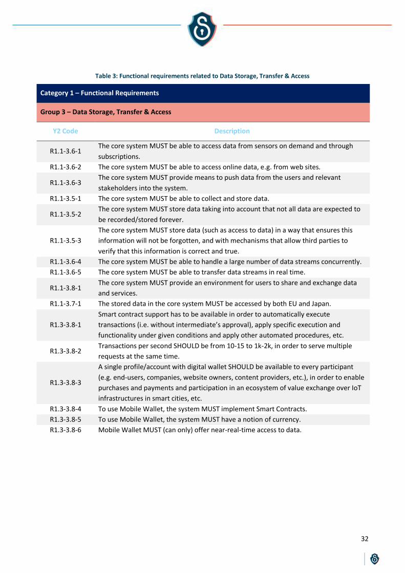
32
Table 3: Functional requirements related to Data Storage, Transfer & Access
Category 1 – Functional Requirements
Group 3 – Data Storage, Transfer & Access
Y2 Code Description
R1.1-3.6-1 The core system MUST be able to access data from sensors on demand and through
subscriptions.
R1.1-3.6-2 The core system MUST be able to access online data, e.g. from web sites.
R1.1-3.6-3 The core system MUST provide means to push data from the users and relevant
stakeholders into the system.
R1.1-3.5-1 The core system MUST be able to collect and store data.
R1.1-3.5-2 The core system MUST store data taking into account that not all data are expected to
be recorded/stored forever.
R1.1-3.5-3
The core system MUST store data (such as access to data) in a way that ensures this
information will not be forgotten, and with mechanisms that allow third parties to
verify that this information is correct and true.
R1.1-3.6-4 The core system MUST be able to handle a large number of data streams concurrently.
R1.1-3.6-5 The core system MUST be able to transfer data streams in real time.
R1.1-3.8-1 The core system MUST provide an environment for users to share and exchange data
and services.
R1.1-3.7-1 The stored data in the core system MUST be accessed by both EU and Japan.
R1.3-3.8-1
Smart contract support has to be available in order to automatically execute
transactions (i.e. without intermediate’s approval), apply specific execution and
functionality under given conditions and apply other automated procedures, etc.
R1.3-3.8-2 Transactions per second SHOULD be from 10-15 to 1k-2k, in order to serve multiple
requests at the same time.
R1.3-3.8-3
A single profile/account with digital wallet SHOULD be available to every participant
(e.g. end-users, companies, website owners, content providers, etc.), in order to enable
purchases and payments and participation in an ecosystem of value exchange over IoT
infrastructures in smart cities, etc.
R1.3-3.8-4 To use Mobile Wallet, the system MUST implement Smart Contracts.
R1.3-3.8-5 To use Mobile Wallet, the system MUST have a notion of currency.
R1.3-3.8-6 Mobile Wallet MUST (can only) offer near-real-time access to data.

33
Table 4: Functional requirements related to Processing, Analytics & Visualisation
Category 1 – Functional Requirements
Group 4 – Processing, Analytics & Visualisation
Y2 Code Description
R1.2-4.9-1 The pilot system MUST include real-time data processing functionalities.
R1.2-4.9-2 The pilot system MUST include edge processing functionalities.
R1.2-4.9-3 The pilot system SHOULD include big data analytics functionalities.
R1.2-4.9-4 The system SHOULD provide a tool to analyse data and extract statistics in a simple and
easily understandable way.
R1.2-4.10-1 The system SHOULD facilitate the visualisation of real-time information in a map or in a
list (physical sensing information).
R1.2-4.10-2 The system SHOULD facilitate the visualisation of historical information in a map or in a
list (physical sensing information).
R1.1-4.9-1 The core system MUST be equipped with any data processing and analysis capabilities
necessary for its core services.
R1.1-4.10-1 The core system SHOULD be equipped with any visualisation capabilities necessary for
its core services.
Table 5: Functional requirements related to Development, Reusability & Exploitability
Category 1 – Functional Requirements
Group 5 – Development, Reusability & Exploitability
Y2 Code Description
R1.3-5.11-1 For MTSA to be used, the reactivity of an environment MUST be modelled in a labelled
transition system.
R1.3-5.11-2 For MTSA to be used, the actions in the model MUST be distinguished into a
controllable one or uncontrollable one.
R1.3-5.11-3 The MTSA MUST not (cannot) address non-functional requirements such as “X must
happen in Y seconds”.
R1.3-5.11-4 The MTSA is based on discrete event systems, therefore continuous values like sensing
data MUST be translated to discrete events.
R1.3-5.11-5 For MTSA to be used, too strict requirements or assumptions on the environment
SHOULD be relaxed.
R1.3-5.11-6 Implementation of the behaviour specification synthesis provided by MTSA MUST be
covered by other efforts.
R1.3-5.11-7 The IoT devices used by Node-RED SHOULD support node.js. Alternatively, the devices
MUST support cross-compiling.

34
Table 6: Non-Functional requirements related to Development, Reusability & Exploitability
Category 2 – Non-Functional Requirements
Group 5 – Development, Reusability & Exploitability
Y2 Code Description
R2.1-5.11-2 The architecture of M-Sec MUST be layered, supporting modularity and high
customisation per use case and application.
R2.1-5.11-3 The components of M-Sec MUST be developed following accepted good programming
practices.
R2.1-5.11-4 The components of M-Sec MUST be developed using proven and trusted languages.
R2.1-5.15-1 The M-Sec system SHOULD have a high manageability and flexibility even for users that
are not considered experts.
R2.1-5.15-2 Common management attributes such as add/delete/update SHOULD be intuitive and
easy to be performed.
R2.1-5.15-3 The M-Sec modularity level SHOULD allow enough independence of all modules so as if
any module needs to be replaced, this will have no consequences to the other modules.
R2.1-5.16-1 The various components of M-Sec ideally SHOULD be portable across major operating
systems.
R2.1-5.16-2 The various components of M-Sec SHOULD be interoperable with other services
implementing common and open standards.
R2.1-5.16-3 The core components of the M-Sec framework SHOULD be extensible to new
unforeseen types of sensors and events captured.
R2.1-5.16-4 M-Sec APIs SHOULD rely on open standards and built upon other existing open
standards where possible.
R2.1-5.16-5 M-Sec COULD provide programming interfaces for application developers to gather
real-time and historic data.
R2.1-5.13-1 The core system SHOULD be designed in a way that ensures the proper function of the
system under high volume and velocities circumstances.
R2.1-5.13-2 Statistics and reports COULD be displayed through a dashboard.
R2.1-5.14-1 The M-Sec system MUST have a high availability and reliability (e.g. more than 98% in
regular operation during the pilots) that can be monitored, measured and audited.
R2.1-5.14-2 In case of failures, measures MUST be taken in order to overcome these in short notice
and additional measures for preventing their occurrence MUST be taken.
R2.1-5.12-1 The local architecture SHOULD be scalable and integrated with others.
R2.1-5.12-2
The M-Sec system SHOULD be able to scale with respect to more input sensors. In this
way, the number of edge nodes within an M-Sec system should not be limited and
more edge nodes should be deployed to handle more sensors.
R2.1-5.12-3 The core system MUST support interworking between different networking protocols,
for example through translation functionality in an IoT gateway.
R2.1-5.12-4 The core system MUST be able to be integrated with existing sensor networks or other
systems.
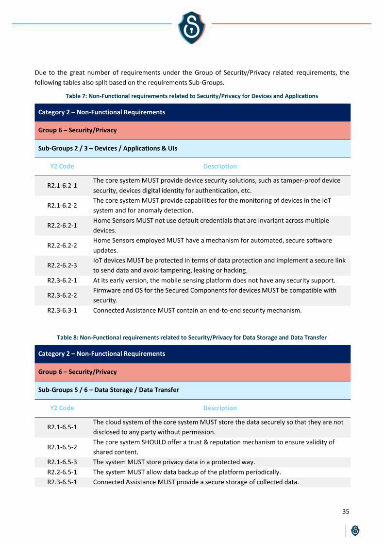
35
Due to the great number of requirements under the Group of Security/Privacy related requirements, the
following tables also split based on the requirements Sub-Groups.
Table 7: Non-Functional requirements related to Security/Privacy for Devices and Applications
Category 2 – Non-Functional Requirements
Group 6 – Security/Privacy
Sub-Groups 2 / 3 – Devices / Applications & UIs
Y2 Code Description
R2.1-6.2-1 The core system MUST provide device security solutions, such as tamper-proof device
security, devices digital identity for authentication, etc.
R2.1-6.2-2 The core system MUST provide capabilities for the monitoring of devices in the IoT
system and for anomaly detection.
R2.2-6.2-1 Home Sensors MUST not use default credentials that are invariant across multiple
devices.
R2.2-6.2-2 Home Sensors employed MUST have a mechanism for automated, secure software
updates.
R2.2-6.2-3 IoT devices MUST be protected in terms of data protection and implement a secure link
to send data and avoid tampering, leaking or hacking.
R2.3-6.2-1 At its early version, the mobile sensing platform does not have any security support.
R2.3-6.2-2 Firmware and OS for the Secured Components for devices MUST be compatible with
security.
R2.3-6.3-1 Connected Assistance MUST contain an end-to-end security mechanism.
Table 8: Non-Functional requirements related to Security/Privacy for Data Storage and Data Transfer
Category 2 – Non-Functional Requirements
Group 6 – Security/Privacy
Sub-Groups 5 / 6 – Data Storage / Data Transfer
Y2 Code Description
R2.1-6.5-1 The cloud system of the core system MUST store the data securely so that they are not
disclosed to any party without permission.
R2.1-6.5-2 The core system SHOULD offer a trust & reputation mechanism to ensure validity of
shared content.
R2.1-6.5-3 The system MUST store privacy data in a protected way.
R2.2-6.5-1 The system MUST allow data backup of the platform periodically.
R2.3-6.5-1 Connected Assistance MUST provide a secure storage of collected data.

36
R2.1-6.6-1
The system MUST include security measures which protect data transmitted over the
network at application level against eavesdropping (encryption and peer
authentication).
R2.1-6.6-2 The core system MUST secure the heterogeneous components involved in the data
stream dissemination, so that they are not cracked by malicious attackers.
R2.1-6.6-3 The core system MUST secure the data streams, so that the data are not tampered in
the network between their source and destination.
R2.1-6.6-4 The core system MUST protect the data streams from malicious attackers at the edge
and distributed cloud platform.
R2.2-6.6-1 Data collected from home sensors MUST be sent over a secure channel and MUST not
be tampered.
R2.3-6.6-1 Connected Assistance MUST provide a secure communication for video call/call.
R2.3-6.6-2 SOX MUST contain end-to-end security mechanism.
Table 9: Non-Functional requirements related to Security/Privacy for Access Control
Category 2 – Non-Functional Requirements
Group 6 – Security/Privacy
Sub-Group 7 – Access Control
Y2 Code Description
R2.1-6.7-1 Mechanisms MUST exist in the core system to prevent access to data and resources by
users not authorized to do so.
R2.1-6.7-2 The core system MUST support mechanisms for authentication and authorisation of the
users, including updates of the users’ proofs of access privileges.
R2.1-6.7-3 The core system MUST be capable of managing different users’ profiles distinguishing
between stakeholders, actors and roles.
R2.1-6.7-4 The core system MUST support an easy to use mechanism that enables the owner of
the data to grant privileges of access to other users, in an understandable way.
R2.1-6.7-5
The pilot system MUST have an access control policy, binding the users with different
profiles, each with different access privileges to data (the owner of the data, person
assigned by them to consult their data –family member or professional-, software
administrator, technical support, security officer, teleoperator, manager…)
R2.1-6.7-6 The pilot system MUST have a dashboard for matching roles to policies and privileges of
access.
R2.1-6.7-7
If there is a role that can assign privileges of access to users on behalf of the owner of
the data, the pilot system MUST enable a way to record the user decision about this
assignation (such as signing a consent form prior to assigning those privileges).
R2.1-6.7-8
The core system MUST keep logs of the interaction that the users have with the system,
especially when getting access to data (not the data themselves). The logs MUST
include the profile the data was accessed from, as well as the action(s) performed

37
(authentication, CRUD on data, access granting/ validation/ revocation/ removal,
signing of consent, etc.).
R2.1-6.7-9 Users MUST only be able to access the data and resources that they inexcusably need
to carry out their tasks (minimum knowledge).
R2.1-6.7-10 The storage of digital entity history information in the core system MUST be restricted
in who can delete and update it.
R2.1-6.7-11
The core system SHOULD require strong passwords (password length; characters from
the groupings and special characters), only permit logins via HTTPS, and ban users when
there is a brute force attack.
R2.1-6.7-12 Passwords, MUST be assigned, distributed and stored in a way that guarantees their
confidentiality and integrity.
R2.1-6.7-13 Passwords SHOULD be changed periodically and during their validity they will be stored
unintelligibly.
Table 10: Non-Functional requirements related to Privacy
Category 2 – Non-Functional Requirements
Group 6 – Security/Privacy
Sub-Group 17 – Privacy
Y2 Code Description
R2.1-6.17-1 The applications and technologies used in M-Sec MUST respect all regulations
concerning the ethical aspects, especially those related to data protection and privacy.
R2.1-6.17-2
The core system MUST store sensitive information (users’ data and detailed logs that
could reveal information about users or secrets about the system itself) in a way that
this information could be permanently deleted.
R2.1-6.17-3 Users MUST be informed about whether and how data they provide/generate are used
by the system (e.g. shared in the Marketplace).
R2.2-6.17-1 The mobile phones IDs of end-users interacting with the city spots where the pilot is
carried out MUST be anonymised.
R2.2-6.17-2
The associated application MUST protect the privacy of the end-user, propose several
levels of management of personal data, and give the option of modifying the privacy
parameters any time.
R2.2-6.17-3
The pilot system MUST show and record the user consent about the usage of their data.
The consent must be CRUD at any moment, and logs of the decisions of the users about
their data should be kept.
R2.2-6.17-4
The pilot system MUST support replying to queries concerning Data Protection of the
users that employ the system. If this request cannot be satisfied in real-time, the
system should guarantee that an answer will be provided in a reasonable time frame.
R2.2-6.17-5 User anonymity MUST be ensured at communication level.
R2.2-6.17-6 Users' data MUST be processed only with the user's consent.

38
R2.2-6.17-7 Users SHOULD have the right to transfer their personal data from a service to another.
R2.2-6.17-8 The pilot system MUST not harm citizens’ privacy; thus, an automated privacy
protection mechanism should be provided.
R2.2-6.17-9 The IDs of citizens and visitors reporting incidents MUST be anonymised.
R2.3-6.17-1
In order to provide anonymity, the blockchain platform MUST be aware of the private
information of a party, providing an anonymous ID and allowing the party’s
transactions to happen only through this without revealing any other information in the
permissioned blockchain network.
R2.3-6.17-2 Connected Assistance does not comply with current law of GDPR. A mechanism
regarding right of deletion, to-be-forgotten and so on MUST be implemented.
R2.3-6.17-3 Deep Counter may harm citizens’ privacy, since the images may contain people walking
in the city. This limitation MUST be resolved by the M-Sec privacy mechanism.
Table 11: General Non-Functional requirements related to Security/Privacy
Category 2 – Non-Functional Requirements
Group 6 – Security/Privacy
Y2 Code Description
R2.3-6.11-1 Honeypot will not cover zero-day attacks.
R2.1-6.18-1 In the core system, security and privacy parameters MUST be (re)configurable.
R2.1-6.18-2 The core system MUST be able to recognise and take under consideration in its design
security attacks.
R2.1-6.18-3 Detailed security assessment and testing MUST be a regular task to avoid system
vulnerabilities.
R2.1-6.18-4 The system MUST return to a state that is known to be secure, after a security breach
occurs or if an upgrade is not successful.
R2.1-6.18-5 The system MUST be protected from replay attacks (message replays at Service level,
packet replay at network and link layer level).
R2.1-6.18-6 The core system MUST deploy auditing and monitoring mechanisms to continuously
collect and report activity metrics and logs from across the system.
R2.1-6.18-7
The core system MUST monitor on-device and related off-device activities such as
network traffic and entry points, process execution and system interactions for any
unexpected behaviour.
R2.2-6.18-1 The pilot system MUST only allow necessary ports to be exposed.
R2.3-6.18-1 The data security solution provided by IoT IDS will depend upon the available resources
in the IoT gateway devices.
R2.3-6.18-2
The attack patterns (signatures) will need to be obtained from other well-known threat
information sources as well so that all possible signatures are available for an improved
security and wider detection reach.
R2.2-6.9-1 The system MUST ensure that processing of information takes place on trusted nodes.
R2.3-6.10-1 Visualization tool is dependent on the alerts and events generated by the IDS.

39
R2.3-6.10-2
Visualisation tool is dependent on the available resources on the IoT gateway devices.
This asset is being tested on following specifications: Intel Atom Processor 500 MHz
Dual Core, 1GB RAM, 4GB Flash, Debian GNU/Linux
The following table gives some more details regarding the sources from which the requirements were
extracted, as well as some statistics. A requirement may come from more than one source, but only the basic
one is being documented.
Table 12: Details on the sources used during the Requirements Extraction
Source Requirements Total %
City authorities R1.2-1.1-(1,2,5), R1.1-1.1-1, R1.2-1.1-1, R1.2-1.2-1, R1.2-4.10-(1,2) 8 6
Consortium R1.1-3.7-1, R1.1-3.8-1, R2.1-6.18-2 3 2
Legislation R1.1-3.5-2, R2.1-6.7-7, R2.1-6.5-3, R2.1-6.17-(1-3), R2.2-6.17-(1-
6,9) 13 9
Partner
R1.3-1.2-5, R2.3-6.2-2, R1.3-3.8-(1-3), R2.3-6.17-1, R1.1-3.5-1,
R1.1-3.6-(1,3), R1.2-4.9-(1,3), R1.1-4.10-1, R2.1-6.7-3, R2.1-6.5-2,
R2.3-6.6-2, R2.3-6.2-1, R2.3-6.17-3, R1.2-2.3-2, R1.1-3.6-(2,4,5),
R1.2-4.9-2, R2.2-6.17-8, R2.1-6.5-1, R2.1-6.6-(2-4), R1.3-1.2-(1-4,6),
R1.2-1.1-2, R1.2-4.9-4, R2.2-6.2-3, R1.3-3.8-(4-6), R1.3-1.2-4, R1.3-
5.11-7, R2.3-6.3-1, R2.3-6.5-1, R2.3-6.6-1, R2.3-6.17-2, R1.2-2.3-
(1,3), R1.1-3.5-3, R2.2-6.2-(1,2), R2.1-6.7-(1,2,5,8,10-12), R2.2-6.5-
1, R2.1-6.6-1, R2.2-6.6-1, R2.1-6.2-(1,2), R2.2-6.9-1, R1.3-5.11-(1-
6), R2.3-6.11-1, R2.3-6.18-(1,2), R2.3-6.10-(1,2)
73 53
Potential End
Users R1.2-2.3-5, R1.2-2.4-(1-5), R1.2-1.1-(3,4,6), R2.1-6.7-4, R2.2-6.17-7 11 8
Security Solution
Providers R2.1-6.7-(6,9,13), R2.1-6.18-(1,3-7), R2.2-6.18-1 10 7
Solution
Providers
R2.1-5.11-(1-4), R2.1-5.15-(1-3), R2.1-5.16-(1-5), R2.1-5.13-(1,2),
R2.1-5.14-(1,2), R2.1-5.12-(1-4), R1.1-4.9-1 21 15
139 100
From the above, requirements can be roughly split in two types, depending on their source: “fundamental”
ones (coming from end users, city authorities, legislation, project’s objectives) which account roughly for 30%
of the requirements, and more technical ones (coming from the partners and solution providers). Also, it can
be seen that about half of the requirements were extracted “internally” (from the consortium partners as a
source), while the rest are based on external input. It should be noted that the M-Sec consortium includes all
necessary stakeholders of the M-Sec value chain. In particular, the consortium includes smart city
infrastructure providers, technology providers as well as service providers and integrators (i.e. the technical
partners from EU and JP side).
The following table gives some more details regarding the extraction process followed.

40
Table 13: Details on the extraction process
Source Requirements Total %
Best Practices
R2.1-5.11-(1-4), R2.1-5.15-(1-3), R2.1-5.16-(1-5), R2.1-5.13-(1,2),
R2.1-5.14-(1,2), R2.1-5.12-(1-4), R1.1-4.9-1, R2.1-6.7-(6,9,13), R2.1-
6.18-(1,3-5), R2.2-6.18-1
29 21
Direct or indirect
communication
R1.2-2.3-5, R1.2-2.4-(1-5), R1.2-1.1-(1-6), R1.1-1.1-1, R1.2-1.1-1,
R1.2-1.2-1, R1.2-4.10-(1,2), R2.1-6.7-4, R2.2-6.17-7 19 14
GDPR & PIPA
study
R1.1-3.5-2, R2.1-6.7-7, R2.1-6.5-3, R2.1-6.17-(1-3),
R2.2-6.17-(1-6,9) 13 9
Internal
knowledge of the
asset
R1.3-3.8-(1-6), R1.3-1.2-(1-5), R1.3-5.11-(1-7), R2.3-6.3-1, R2.3-6.5-
1, R2.3-6.6-(1,2), R2.3-6.11-1, R2.3-6.2-(1,2), R2.3-6.18-(1,2), R2.3-
6.17-(1-3), R2.3-6.10-(1,2)
32 23
Project's
objectives R1.1-3.7-1, R1.1-3.8-1, R2.1-6.18-2 3 2
Technical needs
identification
R1.2-2.3-(1-4,6), R1.1-3.5-(1,3), R1.1-3.6-(1-5), R1.2-1.1-2, R1.2-4.9-
(1-4), R1.1-4.10-1, R2.1-6.7-3, R2.1-6.5-2, R2.2-6.2-(1,2), R2.1-6.18-
(6,7), R2.2-6.17-8
25 18
Vulnerabilities
identification
R2.1-6.7-(1,2,5,8,10-12), R2.1-6.5-1, R2.2-6.5-1, R2.1-6.6-(1-4),
R2.2-6.6-1, R2.1-6.2-(1-3), R2.2-6.9-1 18 13
139 100
The vulnerabilities identification process has provided requirements that are related to “T3.3 Risks & Security
elements”. It should be noted though that the process followed to identify security threats in T3.3 uses a
different and more methodical approach than this of the requirements extraction. Similarly, the requirements
acquired from partners taking under consideration the GDPR & PIPA are related to the study that takes place
in “T5.3 GDPR compliance”, although the approach there is also different (and more methodical). The
following figure summarises in a graphical manner the aforementioned results.
Figure 3—2: M-Sec Requirements Sources details

41
4. Step 3: Requirements Consolidation
4.1 Methodology
The Requirements Consolidation Step (3rd column in Figure 1—1) is the first Step of the Requirements Analysis
Phase, and includes the Requirements Categorisation, the Requirements Versioning, the Requirements Coding
and the Requirements Mapping to UCs and Stakeholders processes.
The Requirements Categorisation process is extremely important and its results are the backbone of the
requirements further analysis, as it has been noticed already in previous section. By grouping requirements, it
becomes easier to study them (since requirements with a similar “mentality” appear together), to merge
them, and to align their description. Moreover, by correlating the requirements groupings to specific
Functional Groups of assets, it becomes possible to directly link the Requirements (subject of T3.1) to the
overall Architecture of the project (subject of T3.2). This linkage is presented in D3.4.
Although a categorisation schema was already provided during Y1, in Y2 it became apparent that a more
elaborate approach should be followed, due to the number of requirements and the complexity of the project.
As such, for each requirement we have identified four different levels of categorisation:
Category: The category of a requirement simply states whether the requirement is:
a functional requirement (Category 1): A requirement that defines specific behaviour or functions.
Broadly speaking, functional requirements define what a system is supposed to do. Indicatively, the
functional view information includes: System functions; Tasks or actions to be performed; Inter-
function relationships; Hardware and software functional relationships; Functional constraints;
Interface requirements.
a non-functional requirement (Category 2): A requirement that specifies criteria that can be used to
judge the operation of a system (quality attributes of a system). Broadly speaking, non-functional
requirements define how a system is supposed to be. They correspond to execution qualities (such as
safety, security and usability, which are observable during operation, at run time) and evolution
qualities (such as testability, maintainability, extensibility and scalability, which are embodied in the
static structure of the system).
Type: The type of a requirement identifies at what level of the overall project the requirement focuses on:
Core System requirement (Type 1): Requirements of this type correspond to requirements that have
to be covered so that the project provides successful primary technical results. They are related to the
constraints and the capabilities of M-Sec’s core system: the final system to be delivered by the end of
the project for other projects and initiatives to reuse or adapt it (more details in D3.4). During Y1,
these requirements were mentioned as “Generic” requirements, but they were only constrained to
functional requirements. For example, the requirement “The core system MUST be able to recognise
and take under consideration in its design security attacks” is a core system one.
Pilot System requirement (Type 2): Requirements of this type correspond to the extra requirements
(beyond the core system ones) needed for the project to deliver successful pilots specifically. They are
related to constraints and the capabilities of the pilot systems (more details in D3.4). During Y1, these
requirements were mentioned as “Use Case specific” requirements. For example, the requirement

42
“The pilot system MUST identify the number of people present at a certain time in a designated spot”
is a pilot system one.
Assets requirement (Type 3): Requirements of this type focus on constraints and needs arising from
the usage of specific assets appearing in the project. These are requirements that have to be
considered for successful integration between assets.
Group: The Group of a requirement identifies to what kind of functionalities, services, features or attributes
the requirement focuses on. The following Groups have been identified.
Data Types & Devices (Group 1)
Applications, UIs, Events & Notifications (Group 2)
Data Storage, Transfer & Access (Group 3)
Processing, Analytics & Visualisation (Group 4)
Development, Reusability & Exploitability (Group 5)
Security/Privacy (Group 6)
Sub-Group: On the same spirit with the Groups identification, a number of sub-groups were identified.
These sub-groups are: Data Types (Sub-Group 1); Devices (Sub-Group 2); Applications & UIs (Sub-Group
3); Events & Notifications (Sub-Group 4); Data Storage (Sub-Group 5); Data Transfer (Sub-Group 6); Access
control (Sub-Group 7); Marketplace (Sub-Group 8); Processing & Analytics (Sub-Group 9); Visualisation
(Sub-Group 10); Design & Development (Sub-Group 11); Scalability (Sub-Group 12); Performance (Sub-
Group 13); Reliability & Availability (Sub-Group 14); Manageability & Flexibility (Sub-Group 15); Openness
& Extensibility (Sub-Group 16); Privacy (Sub-Group 17); General (Sub-Group 18)
The names Groups and Sub-Groups identified are self-explanatory enough to not need further elaboration on
their presentation. It should only be noted that although some Sub-Groups belong only under specific Groups
(e.g. Sub-Group 1 – Data Types goes under Group 1 – Data Types & Devices only), the same is not the case for
all Sub-Groups (e.g. Sub-Group 2 – Devices appears both in Group 1 and Group 6). Following this 2-level
grouping approach makes it possible to produce a wide number of combinations, further enhancing the
categorisation capabilities of our schema.
Compared to the Y1 categorisation schema, the Y2 one is more harmonised and with wider capabilities. For
example, in Y1 the systems/assets requirements distinction (Type) was made only for Functional
requirements. In Y2 though, it was noticed that the same distinction could be expanded to Non-Functional
requirements. Similarly, Non-Functional requirements in Y1 had their own Groups, but Functional
requirements did not have any. However, as it was mentioned, it is the very introduction of the Groups in the
Functional requirements category that enables the linkage of the requirements analysis to the M-Sec
Architecture. Finally, the introduction of Sub-Groups was considered necessary, considering that the
Security/Privacy Category included around half of all the requirements (~60 requirements).
All requirements have been worded, split, edited or merged in such a way so as to belong to no more than
one Category, Type and Sub-Group.
On the topic of Security/Privacy requirements, it should be noted that some of them are constraints, others
are threats that have to be faced and others are required features (and thus can be the solution to actual
threats). On the other hand, D3.5 identifies threats and risks strictly, while using a different approach: instead
of requirements elicitation, it follows the STRIDE methodology. Something similar applies to the case of D5.11
that is related to the GDPR/PIPA compliance of the project. Of course, all three deliverables together (D3.2,
D3.5 and D5.11) are the main input for development, design and integration decisions (Figure 1—3).

43
With the Requirements Categorisation process being completed, the Requirements Coding process becomes
quite simple. Following the Y2 changes to the categorisation schema, all requirements were appointed a new,
Y2 Code which takes the form RX.Y-Z.W-N where R stands for “Requirement”, X is the Category number of the
requirement, Y its Type, Z its Group, W its Sub-Group and N the order of the requirement relative to all other
requirements with the same Category, Type, Group and Sub-Group.
Requirements Versioning is a simple process used to ensure traceability of the requirements throughout the
full lifecycle of the project. First of all, it is identified whether a requirement is a new one (added in Y2) or not
(see Figure 4—1). For each requirement that is not a new one, except for the Y2 Code, the Y1 Code is also
provided. For requirements that were produced by merging Y1 requirements, the Y1 Codes of all those
requirements is identified. In case those requirements belonged to the same Y1 Category and Group, the Y1
Codes of the requirements are mentioned together in a summarised way as RX.Y.(A,B). For example, R1.2.5
combined with R1.2.17 are identified as R1.2.(5,17) for Y1.
Figure 4—1: M-Sec Requirements Coding and Versioning
Requirements Dependencies were also updated in Y2. Due to the extensive coverage of the various relations
between requirements through the improved categorisation schema, it was decided for Y2 to only identify
some links between requirements that do not belong to the same Group or Sub-Group. Requirements that
have a dependency with a whole Group of requirements provide the link as RX.Y-Z.W-*. For example, if a
requirement is dependent toR1.*-6.17-*, that means that the requirements is dependent to all the functional
requirements under Group 6 (Security/Privacy), Sub-Group 17 (Privacy), whereas R1.2-(5,6).7-* means that it
is dependent to all the functional pilot system requirements under Groups 5 and 6, Sub-Group 7. The main
dependencies selected to be documented (in the accompanying spreadsheet) are ones that are not obvious.
The Requirements Mapping to UCs helps us identify on the one hand at which UCs a specific requirement
appears and, on the other hand, which are all the requirements that appear in a specific UC (and thus have to
be fulfilled for the corresponding pilot to be successful). In a similar manner, it is possible to proceed with a
Requirements Mapping to Stakeholders, thus identifying for each requirement which stakeholders are
related to the requirement (and its solution), and for each stakeholder what requirements are considered.
4.2 Results
The following tables present the distribution of requirements among all the Categories, Types, and Groups.
Figure 4—2 also depicts the distribution of requirement among UCs and stakeholders. Similar tables and
graphs can be acquired for the distribution of requirements in Sub-Groups or even the distribution of
requirements of a specific Category, Type and Group into several Sub-Groups. The accompanying spreadsheet
is a powerful tool from which such statistics and summarised views can be extracted.

44
Table 14: Requirements distribution in Categories
Category Requirements Total %
Functional R1.*-*.*-* 57 41
Non-Functional R2.*-*.*-* 82 59
139 100
Table 15: Requirements distribution in Types
Type Requirements Total %
Core System R*.1.*-*.*-* 29 21
Pilot System R*.2.*-*.*-* 19 14
Assets R*.3.*-*.*-* 13 9
139 100
Table 16: Requirements distribution in Groups
Group Requirements Total %
Data Types & Devices R*.*.1-*.*-* 15 11
Applications, UIs, Events & Notifications R*.*.2-*.*-* 11 8
Data Storage, Transfer & Access R*.*.3-*.*-* 16 12
Processing, Analytics & Visualisation R*.*.4-*.*-* 8 6
Development, Reusability & Exploitability R*.*.5-*.*-* 27 19
Security/Privacy R*.*.6-*.*-* 62 45
139 100
Figure 4—2: Number of Requirements per UC and Related Stakeholder
0
10
20
30
40
50
60
70
80
90
100UC1
UC2
UC3UC4
UC5
Service providers
Integrators
End Users
IoT infrastructureproviders
Smart Cities

45
5. Step 4: Requirements Prioritisation &
Scheduling
5.1 Methodology
The Requirements Prioritisation & Scheduling Step (4th column in Figure 1—1) consists of the Requirements
Prioritisation and the Requirements Scheduling processes. The ultimate goal of these two processes is to
provide a quantitative way to identify what priority should be given to the fulfilment of requirements. Three
parameters are taken under consideration in:
Importance: How important is the fulfilment of the requirement to the project.
Feasibility: How easy or difficult it is to fulfil the requirement.
Progress: To what extent the requirement has already been covered.
Figure 5—1: M-Sec Requirements Prioritisation, Progress and Scheduling
For the Importance of a requirement, the MoSCoW method is used. The MoSCoW method is a prioritisation
technique used in management, business analysis, project management, and software development to reach
a common understanding with stakeholders on the importance they place on the delivery of each
requirement. The term MoSCoW itself is an acronym derived from the first letter of each of four prioritisation
categories (Must have, Should have, Could have, and Won't have), with the interstitial Os added to make the
word pronounceable. This prioritisation method was developed by Dai Clegg and first used extensively with
the agile project delivery framework Dynamic Systems Development Method (DSDM)12.
12 https://www.agilebusiness.org/page/ProjectFramework_10_MoSCoWPrioritisation
Scheduling
# Y2 CodeMoSCoW
Priority
MoSCoW
Priority (1-3)
(Technical)
Feasibility
(Technical)
Feasibility (1-3)
Critical
Level
Level of
Fulfilment (0-3)
Level of
Fulfilment (%)Ranking
130 R2.3-6.11-1 Must 3 Medium 2 8 1 33 5
126 R2.3-6.3-1 Must 3 Medium 2 8 1 33 5
33 R1.1-4.9-1 Must 3 Medium 2 8 1 33 5
111 R2.1-6.18-3 Must 3 Medium 2 8 1 33 5
112 R2.1-6.18-4 Must 3 Medium 2 8 1 33 5
105 R2.2-6.9-1 Must 3 Medium 2 8 1 33 5
89 R2.1-6.7-7 Must 3 High 1 7 1 33 4
120 R2.2-6.17-4 Must 3 High 1 7 1 33 4
73 R2.1-5.14-2 Should 2 Low 3 7 1 33 4
64 R2.1-5.15-3 Should 2 Low 3 7 1 33 4
67 R2.1-5.16-3 Should 2 Low 3 7 1 33 4
108 R2.1-6.17-3 Must 3 High 1 7 1 33 4
94 R2.1-6.7-12 Must 3 High 1 7 1 33 4
84 R2.1-6.7-2 Must 3 High 1 7 1 33 4
90 R2.1-6.7-8 Must 3 High 1 7 1 33 4
118 R2.2-6.17-2 Must 3 High 1 7 1 33 4
119 R2.2-6.17-3 Must 3 High 1 7 1 33 4
97 R2.1-6.5-2 Should 2 Medium 2 6 1 33 3
Coding and Versioning Prioritisation Progress

46
In the context of M-Sec, “Must” is used for requirements that are necessary to be covered as soon as possible.
“Should” is used for requirements that are needed to be covered for the project to be deemed successful, but
can be completed at a later stage. “Could” is used for requirements that provide several options for the
coverage of other requirements, and the fulfilment of which is not necessary. “Won’t” requirements are not
identified, since it is considered pointless to list requirements which are not planned to be covered during the
lifetime of the project. Ideally, all “Must” and “Should” requirements have to be covered, but should any
sacrifices have to be made, the “Must” requirements will be prioritised over the “Should” ones.
This prioritisation is included in the wording of the requirements description (in most cases). For core system
and pilot system requirements, this wording is exactly the same with the “MoSCoW Priority” indication at the
corresponding column of the accompanying spreadsheet (see Figure 5—1). However, for assets requirements,
the priority appearing in the description may be different from the one appearing in the “MoSCoW Priority”
column, and that is because a lot of assets requirements are restrictions for the usage of an asset. For example,
to use Asset X, it MUST connect to Asset Y. However, using Asset X in the first place may not be a MUST. Thus,
prioritisation for assets is based on the need for the assets to be used for the project/pilots objectives to be
met, and that is the reason why the wording may not match.
To identify the importance of the requirements in a quantitative way, “Must” has been given a value of “3”,
“Should” a value of “2”, and “Could” a value of “1”.
Regarding the (Technical) Feasibility of a requirement, three values have been identified: “High”, “Medium”,
and “Low”. “High” (relatively easy to fulfil) is given a value of “1”, “Medium” (moderate effort is needed to
fulfil) a value of “2”, and “Low” a value of “3” (a lot of effort is required to complete).
Together, Importance (MoSCoW priority) and Feasibility give an estimation of the Criticality (Critical Level) of
a requirement. In other words, the Criticality identifies how important and hard it is for a requirement to be
fulfilled. A requirement which is a “Must” and hard to complete should have a higher Criticality then a
requirement that is a “Must” but easy to complete. As such, the arithmetic values of the MoSCoW priority and
the Feasibility have to be added together. A simple sum of the two values does not give the wanted result
though. If no weights are used, a “Should” that is really hard to accomplish (2+3 = points) would outrank a
“Must” and easy to accomplish requirement (3+1 = points). However, if we give a weight of 2 to the Importance
of the requirements, this problem is tackled. As such:
𝐶𝑟𝑖𝑡𝑖𝑐𝑎𝑙_𝐿𝑒𝑣𝑒𝑙 = 2 𝑥 𝐼𝑚𝑝𝑜𝑟𝑡𝑎𝑛𝑐𝑒 + 𝐹𝑒𝑎𝑠𝑖𝑏𝑖𝑙𝑖𝑡𝑦
This way, all “Must” requirements will have at least 7 points (2 x 3+1), whereas all “Should” requirements will
have 7 points maximum (2 x 2 + 3). The Critical Level ranges from 3 points (for “Could” and easy to fulfil)
requirements to 9 points (for “Must” and hard to fulfil). The Critical Level of the requirement is a value that is
not expected to be changed during the rest of the project.
What is expected to change is the third parameter: the Progress. A rough estimation for the Progress towards
the fulfilment of each requirement is provided (see Section 6). The Progress values can be “0” for progress less
than 33%, “1” for progress between 33% and 67%, “2” for progress between 67% and 99% and “3” for
completed requirements. The main goal is to combine the values of Criticality and Progress to identify the final
overall priority that has to be given to a requirement right now. A completed “Must” and hard to complete
requirement is expected to get a “0” overall priority (Scheduling). As such:
𝑆𝑐ℎ𝑒𝑑𝑢𝑙𝑖𝑛𝑔 = 𝐶𝑟𝑖𝑡𝑖𝑐𝑎𝑙_𝐿𝑒𝑣𝑒𝑙 − 3 𝑥 𝑃𝑟𝑜𝑔𝑟𝑒𝑠𝑠 = 2 𝑥 𝐼𝑚𝑝𝑜𝑟𝑡𝑎𝑛𝑐𝑒 + 𝐹𝑒𝑎𝑠𝑖𝑏𝑖𝑙𝑖𝑡𝑦 − 3 𝑥 𝑃𝑟𝑜𝑔𝑟𝑒𝑠𝑠

47
Figure 5—2: Requirements Criticality map
By sorting the requirements by the Scheduling value in the accompanying spreadsheet (as presented in Figure
5—1), it is possible to recognise the requirements that are “falling” behind and need further attention.
5.2 Results
The following tables and diagrams present the distribution of requirements among all the various levels of
Importance, Feasibility and Criticality. The Scheduling value is being updated and used during the whole
progress of the project, and thus no details are given about it. However, the accompanying spreadsheet
includes the Scheduling values as they were at the end of M24 of the project.
Table 17: Importance of Requirements
MoSCoW Requirements Total %
Must
R1.1-1.1-1, R1.1-3.5-(1-3), R1.1-3.6-(1-5), R1.1-3.7-1, R1.1-3.8-1, R1.1-4.9-1,
R1.2-1.1-(1-6), R1.2-1.2-1, R1.2-2.3-(1-3), R1.2-4.9-(1,2), R1.3-1.2-(1,2,4), R1.3-
3.8-1, R1.3-5.11-7, R2.1-5.11-(2-4), R2.1-5.12-(3,4), R2.1-5.12-4, R2.1-5.14-1,
R2.1-6.17-(1-3), R2.1-6.18-(1-7), R2.1-6.2-(1,2), R2.1-6.5-(1,3), R2.1-6.6-(1-4),
R2.1-6.7-(1-10,12), R2.2-6.17-(1-9), R2.2-6.18-1, R2.2-6.2-(1-3), R2.2-6.5-1, R2.2-
6.6-1, R2.2-6.9-1, R2.3-6.11-1, R2.3-6.17-(1-3), R2.3-6.18-(1,2), R2.3-6.2-(1,2),
R2.3-6.3-1, R2.3-6.5-1, R2.3-6.6-(1,2)
91 65
Should
R2.1-5.15-3, R2.1-5.16-3, R2.1-5.14-2, R2.1-5.15-(1,2), R1.2-4.9-(3,4), R2.1-6.5-2,
R2.1-6.7-13, R2.1-5.16-(2,4), R2.1-5.13-1, R2.1-5.12-1, R1.1-4.10-1, R1.2-4.10-1,
R2.2-6.17-7, R2.1-5.12-2, R2.1-5.16-1, R1.2-4.10-2, R1.2-2.4-(1,2), R1.3-1.2-5,
R1.2-1.1-1, R2.1-6.7-11, R1.3-3.8-2, R1.3-1.2-3, R2.1-5.11-1, R2.3-6.10-(1,2)
29 21
Could R1.2-1.1-2, R1.2-2.3-(4-6), R1.2-2.4-(3-5), R1.3-3.8-(3-6), R1.3-5.11-(1-6), R2.1-
5.13-2, R2.1-5.16-5 19 14
139 100

48
According to the project where the MoSCoW priority was first used extensively13, typically no more than 60%
“Must” requirements should be provided, whereas the “Could” ones should be around 20%. M-Sec complies
with these directions, since 65% of the requirements are a “Must”, while a 14% of them is a “Could”.
Table 18: Feasibility of Requirements
Feasibility Requirements Total %
High
R1.1-3.5-(1,2), R1.1-3.6-(1-3), R1.2-1.1-(1,3,4,6), R1.2-1.2-1, R1.2-2.3-(1-6),
R1.2-2.4-(1-5), R1.2-4.10-2, R1.3-1.2-(1-5), R1.3-3.8-(1-6), R1.3-5.11-(2-7), R2.1-
5.11-(1,3,4), R2.1-5.13-2, R2.1-5.16-1, R2.1-6.17-(1,3), R2.1-6.7-(2-5,7,8,10-12),
R2.2-6.17-(1-6,9), R2.2-6.18-1, R2.2-6.2-1, R2.2-6.5-1, R2.3-6.10-(1,2), R2.3-
6.10-2, R2.3-6.17-1, R2.3-6.18-(1,2), R2.3-6.2-2
73 53
Medium
R1.1-1.1-1, R1.1-3.5-3, R1.1-3.6-(4,5), R1.1-3.8-1, R1.1-4.10-1, R1.1-4.9-1, R1.2-
1.1-(2,5), R1.2-4.10-1, R1.2-4.9-(1-4), R1.3-5.11-(1,2), R2.1-5.12-(1-4), R2.1-
5.13-1, R2.1-5.14-1, R2.1-5.15-(1,2), R2.1-5.16-(2,4,5), R2.1-6.17-2, R2.1-6.18-
(1-7), R2.1-6.2-(1,2), R2.1-6.5-(1,3), R2.1-6.6-(1-4), R2.1-6.7-(1,6,9,13), R2.2-
6.17-(7,8), R2.2-6.2-(2,3), R2.2-6.6-1, R2.2-6.9-1, R2.3-6.11-1, R2.3-6.17-(2,3),
R2.3-6.2-1, R2.3-6.3-1, R2.3-6.5-1, R2.3-6.6-(1,2)
45 45
Low R2.1-5.14-2, R2.1-5.15-3, R2.1-5.16-3 3 2
139 100
Figure 5—3: Requirements Criticality distribution
From the above it can be seen that there are no “Must” requirements with “Low” Feasibility. By using the
accompanying spreadsheet, the criticality level or priority can also be identified per requirements Category,
Group, UC, etc.
13 https://www.agilebusiness.org/page/ProjectFramework_10_MoSCoWPrioritisation

49
6. Step 5: Requirements Fulfilment
6.1 Methodology & Results
The Requirements Fulfilment Step (5th column in Figure 1—1) consists of all the processes required to identify
how each requirement can be fulfilled and what the current level of fulfilment is. This step is the only one in
T3.1 expected to stay active during Y3. The outcomes of this Step act as input to “T2.4 Overall system validation
and evaluation”. For each requirement, the following fields are filled-in at the accompanying spreadsheet:
Related to (Asset/FG): The asset (and FG) at which the requirement appears (if it does so).
Covered by (Asset/FG): The asset (and FG) that can cover the specific requirement. This section is filled in
by careful study of the available assets, as well as by mapping the Requirements Groups and Sub-Groups
to specific FGs and thus identifying potential assets that could be used. This process is described in D3.4.
Covered through: The general approach followed to cover the requirement. If the requirement is covered
by assets, then some specifications about this usage are presented. In some cases, no asset/FG group
applies but a specific approach (e.g. best practices) has to be followed/ a specific decision has to be made.
Undertaken by: The partner owning the asset that fulfils the solution or following up on the requirement’s
completion.
Level of Fulfilment: The Progress values can be “0” for progress less than 33%, “1” for progress between
33% and 67%, “2” for progress between 67% and 99% and “3” for completed requirements. By using these
values, a worst-case-scenario view is being provided. The level of fulfilment is related to the TRL, IRL and
SRL of the assets, FGs and systems (presented in the Integration deliverables of D2.5-7).
As of Y2, for all requirements, an asset or approach covering them has been identified. The diagram below
shows the current progress towards the fulfilment of all requirements. It should be noted that, by using the
accompanying spreadsheet, it is possible to recognise the progress towards the fulfilment of specific
requirements in a specific Category, Group, UC, etc. A total Progress of ~65% is being observed.
Figure 6—1: Progress towards Requirements Fulfilment

50
7. Conclusions
Requirements analysis plays an important role for the whole lifecycle of the M-Sec project. It is the input for
the M-Sec specification and overall architecture as well as for the validation of the final system and its
evaluation against the desired functionality.
In this document, we have presented in full detail the requirements management methodology, split into two
phases: the requirements elicitation one and the requirements analysis one (Section 1).
In Sections 2 and 3, the presentation of the requirements elicitation phase takes place. More specifically, in
Section 2, an overview of the use cases and a technical overview of the available technologies for the project
are provided, (so as to understand the context of the project and identify the various stakeholders who
represent a holistic value chain). In the sequel, the extraction of requirements is derived from the definition
of the desired functionality of the M-Sec system given from the perspectives of the functional components
and the non-functional attributes that the final system has to expose. The M-Sec system should have specified
functionality to facilitate the use cases and a rich set of non-functional requirements such as scalability,
reliability, availability, manageability, flexibility, modularity, openness, etc. The document (and the
accompanied spreadsheet) provides a consolidated and coded requirements list that is the reference for the
design activities and the implementation and validation of the M-Sec system (Section 3).
Finally, Sections 4, 5 and 6 present in detail major results of the requirements analysis phase that indicate the
relations between the requirements (and between the requirements and functionalities of M-Sec), as well as
their prioritisation and their fulfilment process. These results are taken under consideration during the
planning and monitoring of the development and integration activities of the project and will provide valuable
input for the final validation of the project.
Regarding the requirements analysis per se, quite many interesting results were extracted. For example, it has
been identified that 30% of the requirements are “fundamental” ones (coming from end users, city authorities,
legislation, project’s objectives), with the rest of them being technical ones (coming from the partners and
solution providers). Also, it was noted that about half of the requirements were extracted “internally” (from
the consortium partners as a source), while the rest are based on external input. It should be noted that the
M-Sec consortium includes all necessary stakeholders of the M-Sec value chain. In particular, the consortium
includes smart city infrastructure providers, technology providers as well as service providers and integrators
(i.e. the technical partners from EU and JP side).
M-Sec complies with the MoSCoW priority directions, since 65% of the requirements are a “Must”, while a
14% of them is a “Could”. Also, as of Y2, for all requirements, an asset or approach covering them has been
identified. Finally, the results from the requirements monitoring procedure (Section 6.1) at this stage of the
project indicate that the several technical activities within M-Sec are in good shape (~65% Progress).

51
Annex
The document is accompanied by a spreadsheet that has been the main source for extracting all the statistics
and main lists of requirements (split into categories, groups, etc.), as well as the primary working file which
was used internally by the consortium to gather and extract details for each requirement.
In the spreadsheet, four tabs can be found:
[Version Control]: This tab is being used for partners to track internally changes being made in the
spreadsheet. Since this spreadsheet will keep being used during Y3 (to update the Requirements Progress
and Fulfilment columns in the Requirements tab), it is expected for it to change in the future.
[Definitions]: This includes a brief presentation of the several headings present in the Requirements tab.
The same concepts but in much more detail is presented in Sections 3.1, 4.1, 5.1 and 6.1 of this document.
[Requirements]: This is the main outcome of the spreadsheet and the primary working area used during
the elicitation and the analysis of the requirements. A lot of the content that it provides is presented in
Sections 3.2, 4.2, 5.2 and 6.1, although it is possible to acquire more details in the future (as it will be
explained below).
[Statistics]: In this tab, the various diagrams and tables provided in Sections 3.2, 4.2, 5.2 and 6.1 can be
found.
[Assets & UCs]: This tab briefly presents the necessary details to fill in some columns in the Requirements
tab. Since a lot of information in the main table is codified (e.g. Use Cases are not presented with their title
in the [Requirements] tab), this tab provides a quick reminder or reference for details regarding the assets
(used in the Fulfilment section of the [Requirements] tab) and the use cases (used in the Use Cases section
of the [Requirements] tab).
The spreadsheet is a valuable tool from which information can be grouped and organised so as to be
documented (or visualised) for other activities of the project. By using sorting, filtering and hiding, it is possible
to track the results, status and progress of the requirements management activities through various
perspectives. For example, it is possible to acquire the Requirement Progress for each Sub-Group or Group of
requirements or to identify how specific Groups of requirements are mapped to the various Functional Groups
of the project.
At this stage, the spreadsheet is considered almost finalised. The only sections that will be kept “alive” until
the late stages of the project will be the “Progress” and the “Fulfilment Process” ones in the [Requirements]
tab, so as to keep monitoring the overall progress towards the fulfilment of the requirements during Y3 and
to support the project validation activities at the end of M-Sec.


