1 IN TRO DUC TION 11.1 Scope and defi ni tions 11.2 De scrip tion 21.3 Logic in ter face 21.4 In di ca tor LEDs 2
2 TECH NI CAL DATA 42.1 Op er at ing and stor age data 42.2 Me chani cal data 42.3 Elec tri cal data 4
3 IN STAL LA TION 73.1 Un pack and in spect 73.2 Ad just the elec tri cal con nec tor po si tion (op tional) 73.3 Fit the EXDC to the EXT pump 73.4 Elec tri cal con nec tions 83.4.1 In tro duc tion 83.4.2 Con nect the logic in ter face to your con trol equip ment 83.4.3 Con nect the elec tri cal sup ply 10
4 OP ERA TION 114.1 Start- up 114.2 Op era tion with high in let pres sure or tem pera ture 114.3 Nor mal shut down 124.4 Shut down due to pump un der or over- speed 124.5 Elec tri cal sup ply fail ure 13
5 MAIN TE NANCE 145.1 In tro duc tion 145.2 EXDC LED fault find ing 14
6 STOR AGE AND DIS POSAL 156.1 Stor age 156.2 Dis posal 15
RETURN OF BOC EDWARDS EQUIPMENT
EXDC Tur bo mo lecu lar Pump Drive Mod ules i
Il lus tra tions
Fig ure Ti tle Page
1 The EXDC 32 Dimensions (mm) 53 Schematic diagram of the logic interface connections 9
EXT70 and EXT250 Tu ro molecu lar Pumps B722- 01- 880
EXT351 and EXT501 Tur bo mo lecu lar Pumps B727-20-880
EXT70H, EXT70Hi, EXT250H and EXT250Hi
Com pound Mo lec u lar Pumps B740-01-880
EXT255H and EXT255Hi
Com pound Mo lec u lar Pumps B753-03-880
ii EXDC Tur bo mo lecu lar Pump Drive Mod ules
1 IN TRO DUC TION
1.1 Scope and defi ni tions
This manual provides installation, operation and maintenance instructions for theBOC Edwards EXDC80 and EXDC160 Turbomolecular Pump Drive Modules(abbreviated to EXDC in the remainder of this manual). You must use the EXDCas specified in this manual. If you do not, the protection provided by the EXDCmay be impaired, or you may damage the EXDC, or cause injury to people.
Read this manual before you install and operate the EXDC. Important safetyinformation is highlighted as WARNING and CAUTION instructions; you mustobey these instructions. The use of WARNINGS and CAUTIONS is definedbelow.
WARNING
Warnings are given where failure to observe the instruction could result ininjury or death to people.
CAUTION
Cautions are given where failure to observe the instruction could result indamage to the equipment, associated equipment or process.
The units used throughout this manual conform to the SI international system ofunits of measurement.
In accordance with the recommendations of IEC1010, the following warningsymbols appear on the EXDC:
Caution - refer to accompanying documents
Caution - hot surface.
EXDC Tur bo mo lecu lar Pump Drive Mod ules 1
1.2 De scrip tion
The EXDC controls the electrical supply for a BOC Edwards EXT70, EXT70H,EXT250, EXT255H, EXT351 or EXT501 turbomolecular pump.
The EXDC has no manual controls and can only be operated through the logicinterface. To operate the EXT pump, you must therefore connect the EXDC toyour own control equipment and electrical supply (see Figure 3).
Two models of EXDC are available, the only difference between the two models isthe output power provided to the EXT pump: see Section 2.
1.3 Logic in ter face
The EXDC has a 9-way logic interface connector on the end of the logic interfacecable (Figure 1, item 3). You must use a suitable connector mating half (notsupplied) to connect the EXDC to your own equipment: refer to Section 2.3 forthe connector mating-half type and to Section 3.4 for the electrical connections.
Refer to Table 1 and Figure 3 for detailed information about the logic interfaceconnector pins and their uses.
1.4 In di ca tor LEDs
Refer to Figure 1. The EXDC has four indicator LEDs, as follows:
Phase LEDs (4) These red LEDs are on when the corresponding
phase output to the EXT pump motor is on.
TMP Normal LED (5) This green LED is on when the EXT pump is 80% or
more of full rotational speed.
You can use these LEDs as an aid to fault finding: refer to Section 5.2.
2 EXDC Tur bo mo lecu lar Pump Drive Mod ules
EXDC Tur bo mo lecu lar Pump Drive Mod ules 3
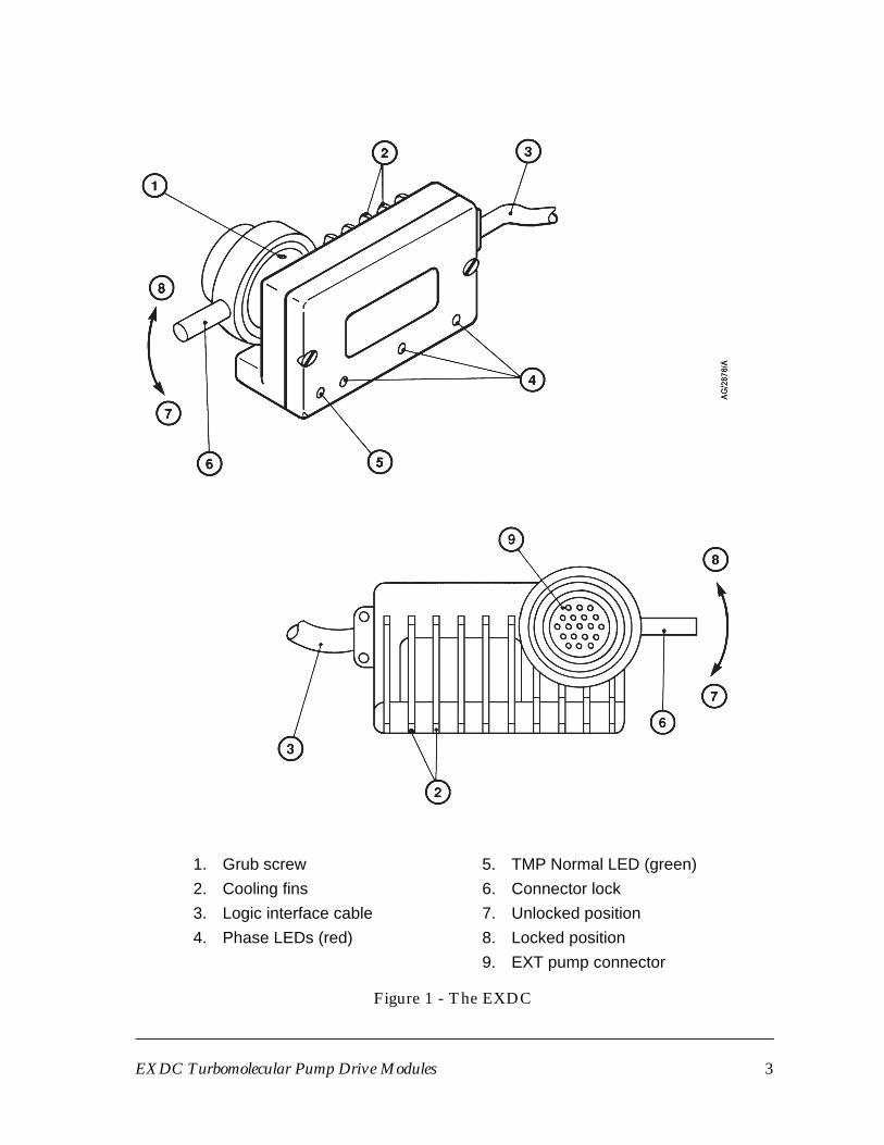
Figure 1 - The EXDC
1. Grub screw
2. Cool ing fins
3. Logic in ter face ca ble
4. Phase LEDs (red)
5. TMP Nor mal LED (green)
6. Con nec tor lock
7. Un locked po si tion
8. Locked po si tion
9. EXT pump con nec tor
2 TECH NI CAL DATA
2.1 Op er at ing and stor age data
Ambient operating temperature range 0 to 40 oC
Ambient storage temperature range -20 to 70 oC
Maximum ambient operating humidity 10 to 95% RH (non-condensing
to DIN 40040)
Maximum operating altitude 3000 m
Cooling Natural convection
Radiated electromagnetic emission EN50081-1
Electromagnetic immunity EN50082-1
2.2 Me chani cal data
Dimensions See Figure 2
Mass 0.2 kg
Enclosure protection IP20 (as defined by IEC529)
Pollution degree IEC664, category 1
2.3 Elec tri cal data
Electrical supply requirements
• The EXDC electr ical supply must meet the requirements ofIEC1010-1/C22.2 1010-1.
• The safety earth (ground) impedance must be < 0.1 Ω.
• The EXDC 0 V is not referenced to earth (ground). Ensure that the electricalsupply offers a path (≤ 22 kΩ) between 0 V and earth (ground).
Maximum continuous output power
EXDC80 80 W
EXDC160 160 W
4 EXDC Tur bo mo lecu lar Pump Drive Mod ules
EXDC Tur bo mo lecu lar Pump Drive Mod ules 5
Figure 2 - Dimensions (mm)
A Ca ble bend ra dius (≥30)
Logic interface
Connector mating half * 9-way D-type male
EXDC electrical supply
Allowable voltage range 70 to 85 V d.c.
Undervoltage lock-out voltage > 63 V
Maximum voltage ripple 2 V r.m.s.
Fuse (or equivalent current
limiting device) rating 3.15 A type ‘T’ IEC approved or
3.2 A time delay fuse UL/CSA
approved
Maximum input current 1.1 A (EXDC80)
2.2 A (EXDC160)
Start/stop control input signal
Start control voltage: low (close) < 0.8 V d.c.
Stop control voltage: high (open) 4 to 24 V d.c.
Speed analogue output
Output voltage 0 to +10 V d.c. (directly
proportional to pump speed,
that is 0 to 10 V ≅ 0 to 100%
of pump speed)
Output impedance 0.1Ω
Minimum load ≥ 5 kΩTMP Normal status output
Type Open collector transistor
< 80 % Off (pull up to 15 V d.c.)
≥ 80 % On (< 0.8 V d.c.)
Rating 20 mA
* Not supplied
6 EXDC Tur bo mo lecu lar Pump Drive Mod ules
3 IN STAL LA TION
3.1 Un pack and in spect
Remove all packing materials and check the EXDC. If the EXDC is damaged,notify your supplier and the carrier in writing within three days; state the ItemNumber of the EXDC together with your order number and your supplier’sinvoice number. Retain all packing materials for inspection. Do not use theEXDC if it is damaged.
If the EXDC is not to be used immediately, store the EXDC in suitableconditions, as described in Section 6.
3.2 Ad just the elec tri cal con nec tor po si tion (op tional)
CAUTION
Do not turn the pump electrical connector more than 180o from itsorientation as supplied. If you do, you may damage the wires inside
the EXDC.
Refer to Figure 1. Use the following procedure to adjust the position of the EXTpump connector (9) and connector lock (6) with respect to the EXDC body.
1. Use a hexagonal key to loosen the grub screw (1).
2. Turn the connector (9) and lock (6) to the required orientation: you can turnthe connector and lock up to 180o clockwise or anticlockwise.
3. Tighten the grub screw (1) to secure the connector and connector lock.
3.3 Fit the EXDC to the EXT pump
1. Refer to Figure 1. Look at the front of the EXDC (that is, with the LEDs (4, 5)towards you), then turn the connector lock (6) fully anticlockwise (indirection 7).
2. Fit the connector (9) directly to the pump to Controller connector on theEXT pump: refer to the EXT pump instruction manual.
3. Turn the lock (6) fully clockwise (in direction 8) to lock the connectors andsecure the EXDC in position.
EXDC Tur bo mo lecu lar Pump Drive Mod ules 7
3.4 Elec tri cal con nec tions
3.4.1 In tro duc tion
Use a suitable connector mating half (not supplied) to connect the electricalsupplies and your control equipment to the connector on the logic interface cable(Figure 1, item 3). When you make the electrical connections to the EXDCdescribed in the following sections, refer to Table 1 for full details of the logicinterface connections and to Figure 3 for a schematic diagram of the connections.
Pin number Signal Polarity Use
1 Start/Stop control input - Close * to start EXTpump.
2 TMP Normal status output - Closed * when EXTpump speed is 80%or more of fullrotational speed.
3 Earth (ground) -
4 Pump speed analogue output Positive
5, 6 Electrical supply: 0 V -
7, 8 Electrical supply: 80 V Positive
* With respect to pins 5 or 6.
Table 1 - Logic interface connector pins
3.4.2 Con nect the logic in ter face to your con trol equip ment
1. Connect your control equipment to the start/stop control input pins of yourlogic interface mating half to start/stop the EXT pump as required:
• Link (close) the start/stop con trol in put (pin 1) to pins 5 or 6 to start theEXT pump.
• Un link (open) the start/stop con trol in put (pin 1) from pins 5 or 6 to stopthe EXT pump.
2. Connect your control equipment to the pump speed analogue output (pin 4)and to pins 5 or 6 of your logic interface mating half to monitor the speedoutput of the EXDC.
(Continued on page 10)
8 EXDC Tur bo mo lecu lar Pump Drive Mod ules
EXDC Tur bo mo lecu lar Pump Drive Mod ules 9
Figure 3 - Schematic diagram of the logic interface connections
A EXDC logic in ter face plug
B Mat ing half to EXDC logic in ter face plug
4. D. C. re lay (op tional)
5. Re lay power sup ply (op tional)
6. Volt me ter
1. Start/stop switch
2. Elec tri cal sup ply
3. Back EMF sup pres sion di ode (op tional)
3. Connect your control equipment to the TMP normal status output (pin 2)and to pins 5 or 6 of your logic interface mating half. You can use the output tocontrol other devices in your pumping system. The output can drive a lowpower relay of up to 24 V coil rating.
3.4.3 Con nect the elec tri cal sup ply
WARNING
Ensure that the EXDC is earthed (grounded) as required byIEC1010-1\C22.2 1010-1 and all local legislative requirements, and observe
all appropriate safety precautions for the safe installation and handling ofelectrical equipment. If you do not, there will be a danger of injury or death
to people by electric shock.
WARNING
Incorporate a suitable isolation device in the electrical supply, close to theEXDC. If you do not, you will not be able to switch off the EXDC in an
emergency.
WARNING
Incorporate suitable fuses or current limiting devices in the electrical supplycircuit. If you do not and a fault develops, the EXDC may be damaged and
there will be a danger of injury or death to people by electric shock.
Connect suitable electrical supplies to pins 5 to 8 of your connector mating half.When you connect the supplies:
• Incorporate a suitable fuse or current limiting devices in your externalelectrical supply: the rating of the fuse or current limiting device must besuitable for your electrical supply.
• Incorporate suitable fuses or current limiting devices in the nominal 80 V lines:refer to Section 2 for the fuse/current limiting device rating.
• Incorporate an isolation switch.
10 EXDC Tur bo mo lecu lar Pump Drive Mod ules
4 OP ERA TION
WARNING
Do not disconnect the EXDC from the EXT pump when the pump isoperating. At full speed, the EXT pump motor generates 48 V RMS whichis accessible at the pump to Controller electrical connection, and there may
be a risk of injury by electric shock.
CAUTION
Do not disconnect the EXDC from, or reconnect the EXDC to, the EXTpump if the electrical supply to the EXDC is on, or if the EXT pump is
rotating. If you do, you can damage the EXDC.
4.1 Start- up
Notes: You can start the backing pump and the EXT pump at the same time; the EXT
pump will not be damaged and can operate as an effective baffle. However, if the
system pressure remains too high, the EXT pump may not reach 80% of full
rotational speed and the TMP Normal status output signal will not be set.
Use the following procedure to start up your system. This procedure assumes thatyou will manually operate the vent-valve and the backing pump.
1. Switch on the electrical supply to the EXDC.
2. Close the vent-valve (if fitted) and start the backing pump.
3. Start the EXT pump: close the Start/Stop control input on the logic interfaceconnector.
4.2 Op era tion with high in let pres sure or tem pera ture
If the EXT pump inlet pressure rises, the power supplied by the EXDC to thepump-motor will increase to counteract the gas frictional load. The pumprotational speed will remain constant until the EXDC peak power level is reached;beyond this power level, the speed of the pump will start to reduce.
(Continued on page 12)
EXDC Tur bo mo lecu lar Pump Drive Mod ules 11
Temperature sensors in the EXDC and the EXT pump are monitored by theEXDC. If the EXDC detects that the pump temperature or its own temperature istoo high, the power supplied to the pump-motor is reduced; the pump may nottherefore be able to maintain full rotational speed if it is too hot.
Refer to the EXT pump instruction manual for the maximum allowable inletpressure and for the pump operating temperature ranges, and refer to Section 2.3for the maximum EXDC output power.
4.3 Nor mal shut down
Use the following procedure to shut down your system. This procedure assumesthat you will manually operate the vent-valve and the backing pump. Refer to theInstruction Manual for the EXT pump for details of the maximum allowable ventrate.
1. Select Stop: open the Start/Stop control input on the logic interfaceconnector.
2. Open the vent-valve after the EXT pump speed has fallen to below 50% of fullrotational speed.
3. Switch off the backing pump.
4.4 Shut down due to pump un der or over- speed
CAUTION
Shut down the EXT pump if its speed falls to below 50% of full rotationalspeed. If you do not, the EXT pump may be damaged.
You must use the speed analogue output to monitor the speed of the EXT pump.If the pump speed falls to below 50% of its full rotational speed, this means thatthere is high inlet pressure or temperature, or that there is a fault in the EXT pump(for example, the bearings may have failed).
If the pump speed falls to below 50% of its full rotational speed, you musttherefore switch off the EXT pump (open the start/stop control input) to preventdamage to the pump.
12 EXDC Tur bo mo lecu lar Pump Drive Mod ules
The EXDC has an electronic EXT pump speed control system. This controlsystem prevents operation of the EXT pump at over 100% of its normal fullrotational speed (as operation above this speed reduces bearing operational life).
If required, you can monitor the speed analogue output and configure yourcontrol equipment to switch off the EXT pump if its speed exceeds 100% of fullrotational speed.
4.5 Elec tri cal sup ply fail ure
WARNING
If the Start/Stop control signal on the logic interface connector is set to Start,the EXDC will automatically restart the EXT pump when the electricalsupply is restored after an electrical supply failure. Ensure that people
cannot be injured by the rotating rotor blades of the EXT pump.
If the electrical supply to the EXDC fails when the EXT pump is rotating, themotor of the EXT pump acts as a generator and the power generated can be usedas the electrical supply for the associated control logic connected to the EXDC.
You can connect a suitable d.c. to d.c. convertor to the 80 V supply pins (pins 7, 8)on your logic interface mating half; the voltage on these pins is maintained at 50 Vd.c. during external electrical supply failure.
EXDC Tur bo mo lecu lar Pump Drive Mod ules 13
5 MAIN TE NANCE
5.1 In tro duc tion
The EXDC has no parts which can be serviced by the user. If necessary, return theEXDC to your supplier or BOC Edwards for repair or replacement.
5.2 EXDC LED fault find ing
Symptom Check Action
None of the LEDsare on.
Has the EXDCelectrical supplyfailed ?
Ensure that the electricalsupply is switched on and thatthe fuses (and current limitingdevices) have not beentripped.
The Normal LEDdoes not go on.
Is there a leak in thevacuum system ?
Inspect the vacuum systemand seal any leaks found.
Is the EXT pumpfaulty ?
Inspect the EXT pump andcheck that it operates correctlywith another EXDC or EXCTurbomolecular PumpController. If necessary,replace the EXT pump.
Only one phaseLED is on.
Is the EXT pumpfaulty ?
Inspect the EXT pump andcheck that it operates correctlywith another EXDC or EXCTurbomolecular PumpController. If necessary,replace the EXT pump.
(Any of theabove.)
- If all the previous checks andactions have been made andthe fault symptom is tillpresent, the EXDC may befaulty: contact your supplier orBOC Edwards.
Table 2 - EXDC LED fault finding
14 EXDC Tur bo mo lecu lar Pump Drive Mod ules
6 STOR AGE AND DIS POSAL
6.1 Stor age
Fit protective covers over the electrical connections and store the EXDC in cleandry conditions until required.
When required for use, prepare and install the EXDC as described in Section 3 ofthis manual.
6.2 Dis posal
Dispose of the EXDC and any components safely in accordance with all local andnational safety and environmental requirements.
EXDC Tur bo mo lecu lar Pump Drive Mod ules 15
Return of BOC Edwards Equipment - Procedure
Form HS1
INTRODUCTION
Before returning your equipment, you must warn BOC Edwards if substances you used (and produced)in the equipment can be hazardous. This information is fundamental to the safety of our Service Centreemployees and will determine the procedures employed to service your equipment.Complete the Declaration (HS2) and send it to BOC Edwards before you dispatch theequipment. It is important to note that this declaration is for BOC Edwards internal use only, andhas no relationship to local, national or international transportation safety or environmentalrequirements. As the person offering the equipment for shipment, it is your responsibility to ensurecompliance with applicable laws.
GUIDELINES
• Equipment is 'uncontaminated' if it has not been used, or if it has only been used with substancesthat are not hazardous. Your equipment is 'contaminated' if it has been used with any substancesclassified as hazardous under EU Directive 67/548/EEC (as amended) or OSHA Occupational Safety(29 CFR 1910).
• If your equipment has been used with radioactive substances, biological or infectious agents,mercury, polychlorinated biphenyls (PCB’s), dioxins or sodium azide, you must decontaminate itbefore you return it to BOC Edwards. You must send independent proof of decontamination (forexample a certificate of analysis) to BOC Edwards with the Declaration (HS2). Phone BOCEdwards for advice.
• If your equipment is contaminated, you must either:• Remove all traces of contamination (to the satisfaction of laws governing the transportation of
dangerous/hazardous substances).• Or, properly classify the hazard, mark, manifest and ship the equipment in accordance with
applicable laws governing the shipment of hazardous materials.Note: Some contaminated equipment may not be suitable for airfreight.
PROCEDURE
1. Contact BOC Edwards and obtain a Return Authorisation Number for your equipment.2. Complete the Return of BOC Edwards Equipment - Declaration (HS2).3. If the equipment is contaminated, you must contact your transporter to ensure that you properly
classify the hazard, mark, manifest and ship the equipment, in accordance with applicable lawsgoverning the shipment of contaminated/hazardous materials. As the person offering the equipmentfor shipment, it is your responsibility to ensure compliance with applicable law. Note: Equipmentcontaminated with some hazardous materials, such as semiconductor by-products,may not be suitable for airfreight - contact your transporter for advice.
4. Remove all traces of hazardous gases: pass an inert gas through the equipment and any accessoriesthat will be returned to BOC Edwards. Where possible, drain all fluids and lubricants from theequipment and its accessories.
5. Seal up all of the equipment's inlets and outlets (including those where accessories were attached)with blanking flanges or, for uncontaminated product, with heavy gauge tape.
6. Seal equipment in a thick polythene/polyethylene bag or sheet.7. If the equipment is large, strap the equipment and its accessories to a wooden pallet. If the
equipment is too small to be strapped to a pallet, pack it in a suitable strong box.8. Fax or post a copy of the Declaration (HS2) to BOC Edwards. The Declaration must arrive before
the equipment.9. Give a copy of the Declaration (HS2) to the transporter. You must tell your transporter if the
equipment is contaminated.10. Seal the original Declaration in a suitable envelope: attach the envelope securely to the outside of
the equipment package, in a clear weatherproof bag.WRITE YOUR RETURN AUTHORISATION NUMBER CLEARLY ON THEOUTSIDE OF THE ENVELOPE OR ON THE OUTSIDE OF THE EQUIPMENTPACKAGE.P
900-
70-0
00 Is
sue
K
Return of BOC Edwards Equipment - Declaration
Form HS2
You must:
• Know about all of the substances which have been used and produced in the equipment before you complete this Declaration
• Read the Return of BOC Edwards Equipment - Procedure (HS1) before you complete this Declaration
• Contact BOC Edwards to obtain a Return Authorisation Number and to obtain advice if you have any questions
• Send this form to BOC Edwards before you return your equipment
Return Authorisation Number:
Equipment/System Name_________________________
Part Number _________________________________
Serial Number_________________________________
Has the equipment been used, tested or operated ?
YES � Go to Section 2 NO � Go to Section 4
IF APPLICABLE:
Tool Reference Number_________________
Process ______________________________
Failure Date___________________________
Serial Number ofReplacement Equipment_________________
Are any substances used or produced in the equipment:
• Radioactive, biological or infectious agents, mercury, poly chlorinated biphenyls (PCBs), dioxins or sodium azide? (if YES, see Note 1) YES � NO �
• Hazardous to humanhealth and safety? YES � NO �
Note 1 : BOC Edwards will not accept delivery of any equipment that is contaminated with radioactive substances, biological/infectious agents, mercury, PCB’s, dioxins or sodium azide, unless you:
• Decontaminate the equipment• Provide proof of decontamination
YOU MUST CONTACT BOC EDWARDS FOR ADVICE
BEFORE YOU RETURN SUCH EQUIPMENT
Print your name:_________________________________Print your job title:_________________________
Print your organisation:____________________________________________________________________
Print your address:_______________________________________________________________________
_______________________________________________________________________Telephone number: ___________________________Date of equipment delivery: ______________
I have made reasonable enquiry and I have supplied accurate information in thisDeclaration. I have not withheld any information, and I have followed the Return ofBOC Edwards Equipment - Procedure (HS1).