Classification and specification of reusable process artefacts Project acronym: COMPAS Project name: Compliance-driven Models, Languages, and Architectures for Services Call and Contract: FP7-ICT-2007-1 Grant agreement no.: 215175 Project Duration: 01.02.2008 – 28.02.2011 (36 months) Co-ordinator: TUV Technische Universitaet Wien (AT) Partners: CWI Stichting Centrum voor Wiskunde en Informatica (NL) UCBL Université Claude Bernard Lyon 1 (FR) USTUTT Universitaet Stuttgart (DE) TILBURG UNIVERSITY Stichting Katholieke Universiteit Brabant (NL) UNITN Universita degli Studi di Trento (IT) TARC-PL Telcordia Poland (PL) THALES Thales Services SAS (FR) PWC Pricewaterhousecoopers Accountants N.V. (NL) This project is supported by funding from the Information Society Technologies Programme under the 7th Research Framework Programme of the European Union. D4.3 Version: 1.0 Date: 2010-07-31 Dissemination status: PU Document reference: D4.3
Transcript
Classification and specification of reusable process artefacts
Project acronym: COMPAS
Project name: Compliance-driven Models, Languages, and Architectures for Services
Co-ordinator: TUV Technische Universitaet Wien (AT)
Partners: CWI Stichting Centrum voor Wiskunde en Informatica (NL)
UCBL Université Claude Bernard Lyon 1 (FR)
USTUTT Universitaet Stuttgart (DE)
TILBURG UNIVERSITY Stichting Katholieke Universiteit Brabant (NL)
UNITN Universita degli Studi di Trento (IT)
TARC-PL Telcordia Poland (PL)
THALES Thales Services SAS (FR)
PWC Pricewaterhousecoopers Accountants N.V. (NL)
This project is supported by funding from the Information Society Technologies Programme under the 7th Research Framework Programme of the European Union.
D4.3 Version: 1.0
Date: 2010-07-31 Dissemination status: PU Document reference: D4.3
FP7-215175 COMPAS D4.3v1.0
File: D4.3_Classification-and-specification-of-reusable-process-artefacts.doc Page 2 of 54
Project no. 215175
COMPAS
Compliance-driven Models, Languages, and Architectures for Services
Specific Targeted Research Project
Information Society Technologies
Start date of project: 2008-02-01 Duration: 36 months
D4.3 Classification and specification of reusable process artefacts
Revision 1.0
Due date of deliverable: 2010-07-31
Actual submission date: 2010-07-31
Organisation name of lead partner for this deliverable:
UCBL - Université Claude Bernard Lyon 1, France
Contributing partners:
USTUTT- Universitaet Stuttgart, Germany
TUV - Technische Universitaet Wien, AT
UNITN - University of Trento, IT
Project funded by the European Commission within the Seventh Framework Programme
Dissemination Level
PU Public X
PP Restricted to other programme participants (including the Commission Services)
RE Restricted to a group specified by the consortium (including the Commission Services)
CO Confidential, only for members of the consortium (including the Commission Services)
FP7-215175 COMPAS D4.3v1.0
File: D4.3_Classification-and-specification-of-reusable-process-artefacts.doc Page 3 of 54
History chart
Issue Date Changed page(s) Cause of change Implemented by
0.1 2010-05-03 All sections New document, added content
Disclaimer: The information in this document is subject to change without notice. Company or product names mentioned in this document may be trademarks or registered trademarks of their respective companies.
All rights reserved.
The document is proprietary of the COMPAS consortium members. No copying or distributing, in any form or by any means, is allowed without the prior written agreement of the owner of the property rights.
This document reflects only the authors’ view. The European Community is not liable for any use that may be made of the information contained herein.
FP7-215175 COMPAS D4.3v1.0
File: D4.3_Classification-and-specification-of-reusable-process-artefacts.doc Page 4 of 54
Figure 14 APQC process classification framework [APQC09] ......................................... 22
Figure 15 The classification criteria for fragmentation techniques [MDK+09] ................. 30
Figure 16 Example of an execution trace ........................................................................... 32
Figure 17 General principle of fragmentation .................................................................... 33
Figure 18 Beer et al’s. Algorithm [BBC+09] ..................................................................... 35
Figure 19 Examples of explanation of traces ..................................................................... 36
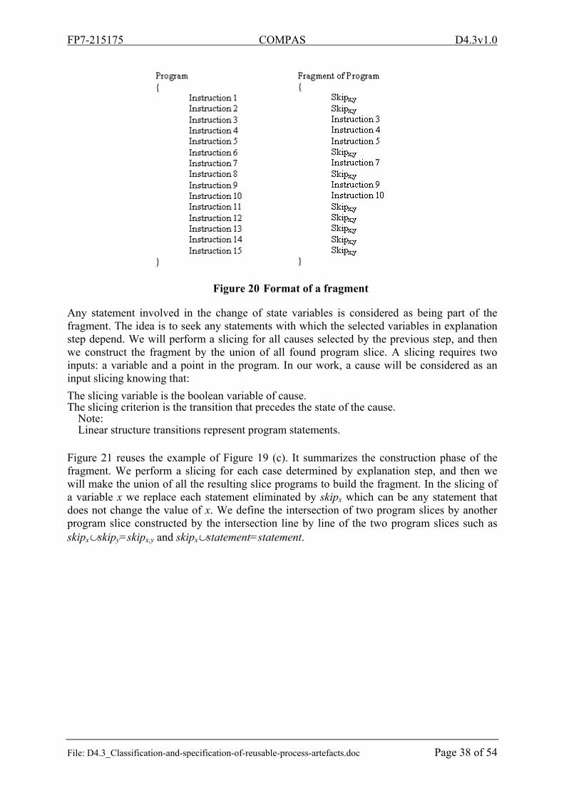
Figure 20 Format of a fragment .......................................................................................... 38
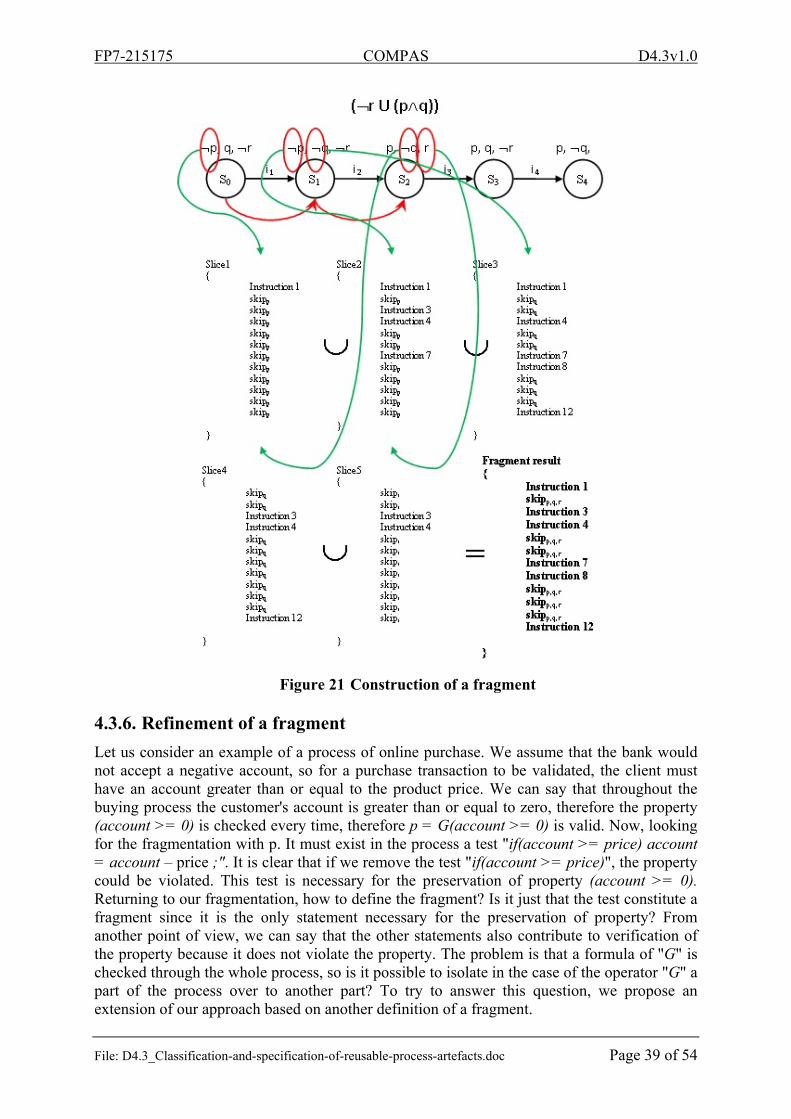
Figure 21 Construction of a fragment ................................................................................. 39
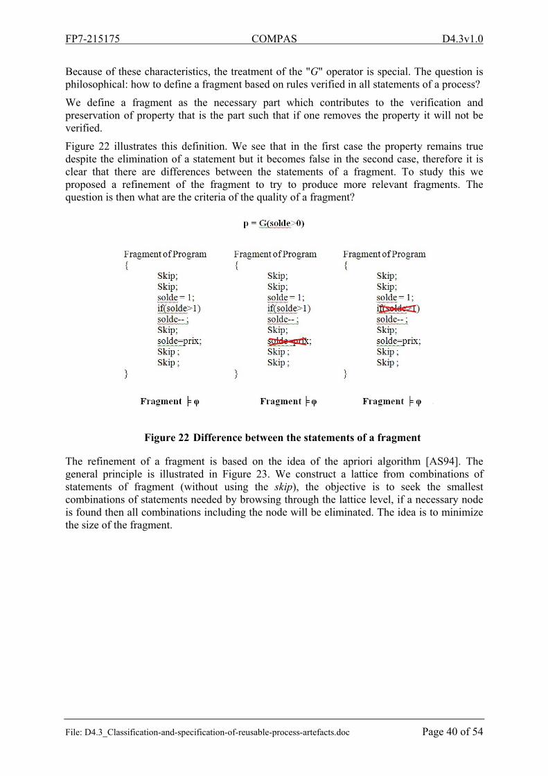
Figure 22 Difference between the statements of a fragment .............................................. 40
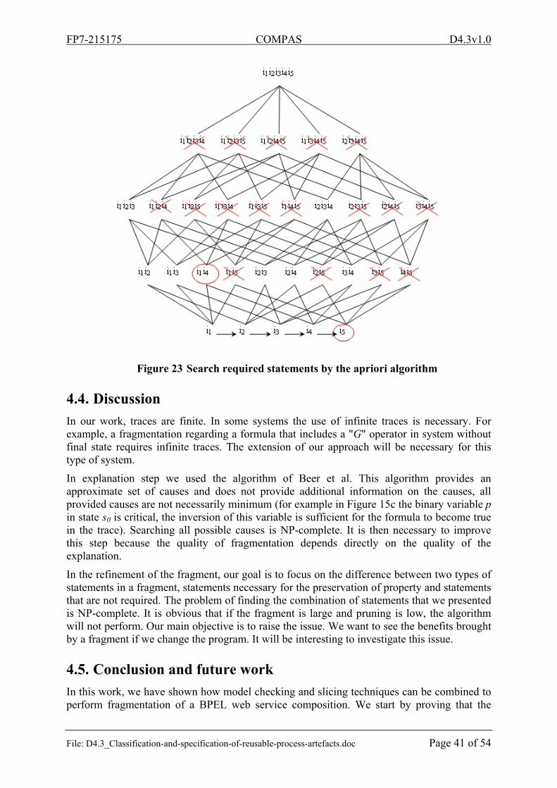
Figure 23 Search required statements by the apriori algorithm .......................................... 41
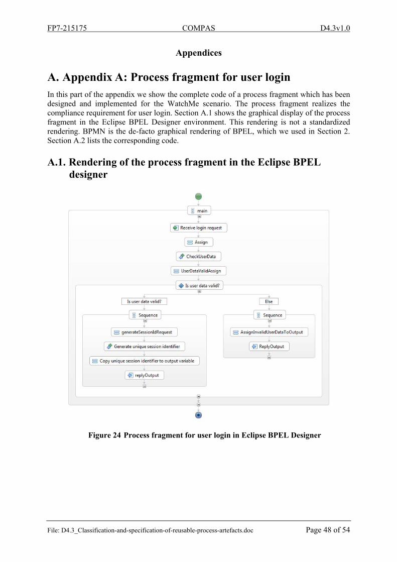
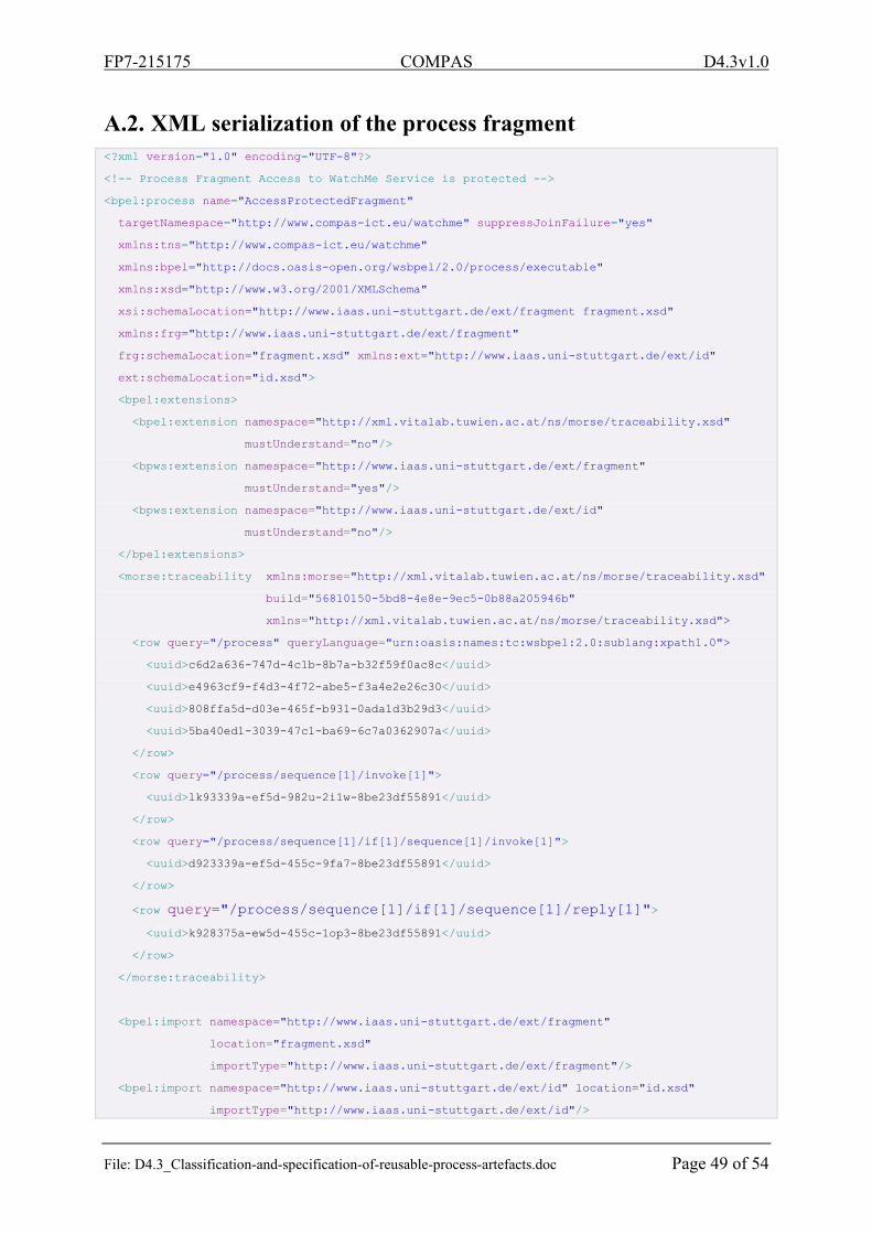
Figure 24 Process fragment for user login in Eclipse BPEL Designer ............................... 48
FP7-215175 COMPAS D4.3v1.0
File: D4.3_Classification-and-specification-of-reusable-process-artefacts.doc Page 6 of 54
List of tables
Table 1 Comparison of models/approaches ........................................................................ 23
List of listings
Listing 1 Process fragment for avoidance of infinite waits [SKL+10] ................................. 13
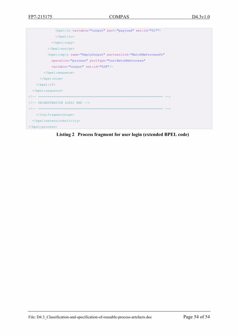
Listing 2 Process fragment for user login (extended BPEL code) ........................................ 54
FP7-215175 COMPAS D4.3v1.0
File: D4.3_Classification-and-specification-of-reusable-process-artefacts.doc Page 7 of 54
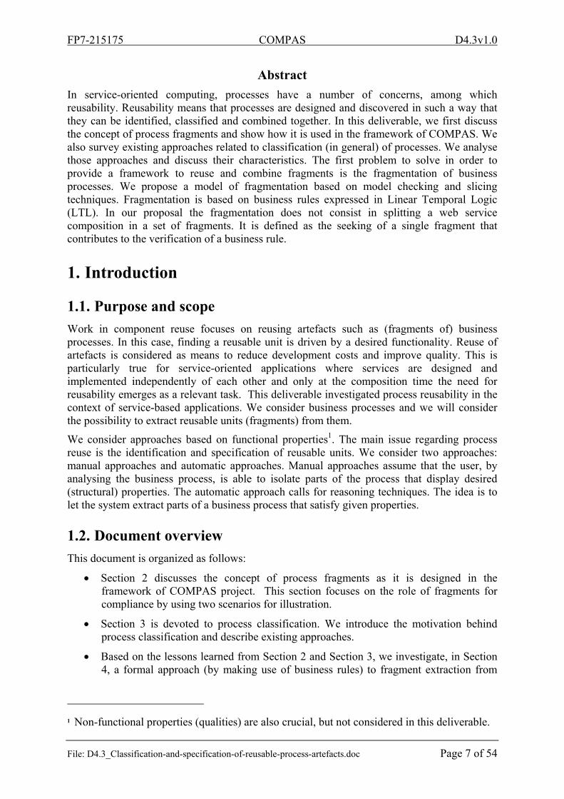
Abstract
In service-oriented computing, processes have a number of concerns, among which reusability. Reusability means that processes are designed and discovered in such a way that they can be identified, classified and combined together. In this deliverable, we first discuss the concept of process fragments and show how it is used in the framework of COMPAS. We also survey existing approaches related to classification (in general) of processes. We analyse those approaches and discuss their characteristics. The first problem to solve in order to provide a framework to reuse and combine fragments is the fragmentation of business processes. We propose a model of fragmentation based on model checking and slicing techniques. Fragmentation is based on business rules expressed in Linear Temporal Logic (LTL). In our proposal the fragmentation does not consist in splitting a web service composition in a set of fragments. It is defined as the seeking of a single fragment that contributes to the verification of a business rule.
1. Introduction
1.1. Purpose and scope
Work in component reuse focuses on reusing artefacts such as (fragments of) business processes. In this case, finding a reusable unit is driven by a desired functionality. Reuse of artefacts is considered as means to reduce development costs and improve quality. This is particularly true for service-oriented applications where services are designed and implemented independently of each other and only at the composition time the need for reusability emerges as a relevant task. This deliverable investigated process reusability in the context of service-based applications. We consider business processes and we will consider the possibility to extract reusable units (fragments) from them.
We consider approaches based on functional properties1. The main issue regarding process reuse is the identification and specification of reusable units. We consider two approaches: manual approaches and automatic approaches. Manual approaches assume that the user, by analysing the business process, is able to isolate parts of the process that display desired (structural) properties. The automatic approach calls for reasoning techniques. The idea is to let the system extract parts of a business process that satisfy given properties.
1.2. Document overview
This document is organized as follows:
Section 2 discusses the concept of process fragments as it is designed in the framework of COMPAS project. This section focuses on the role of fragments for compliance by using two scenarios for illustration.
Section 3 is devoted to process classification. We introduce the motivation behind process classification and describe existing approaches.
Based on the lessons learned from Section 2 and Section 3, we investigate, in Section 4, a formal approach (by making use of business rules) to fragment extraction from
1 Non-functional properties (qualities) are also crucial, but not considered in this deliverable.
FP7-215175 COMPAS D4.3v1.0
File: D4.3_Classification-and-specification-of-reusable-process-artefacts.doc Page 8 of 54
business processes. The extraction is automatic and it is property-oriented. Doing so, fragments can be classified according to the properties they are built from.
1.3. Definitions and glossary
The most important terminology concerning the COMPAS project is listed on the public COMPAS Web-Site [D7.1] available at http://www.compas-ict.eu section terminology. This helps to make the overall COMPAS approach more comprehensive for the general public. In the following the definitions of terms important for this deliverable are provided.
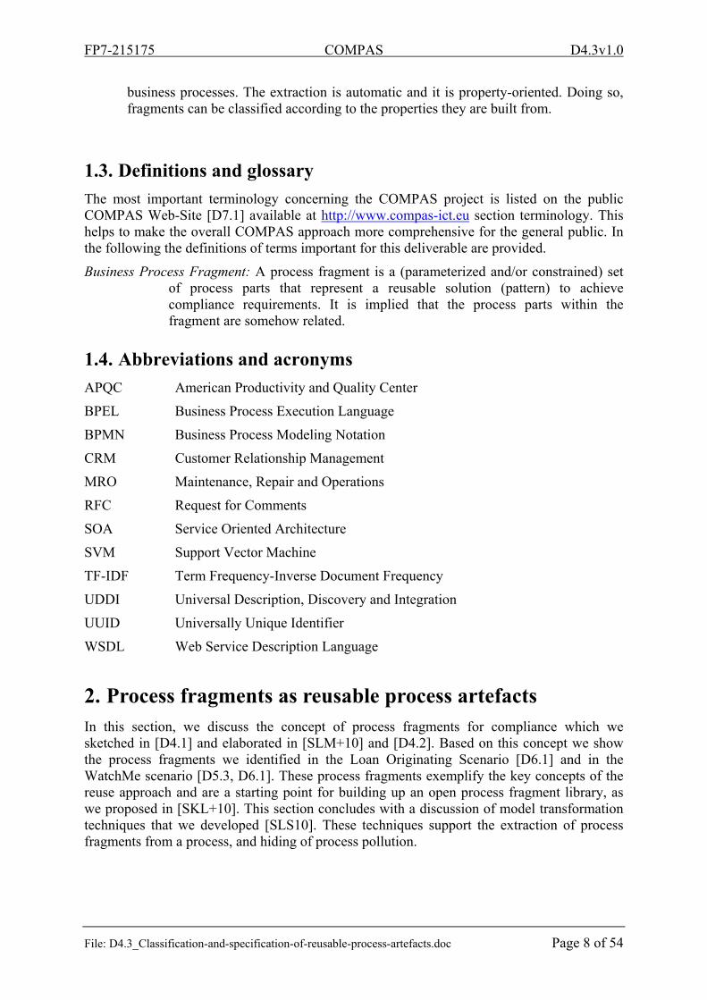
Business Process Fragment: A process fragment is a (parameterized and/or constrained) set of process parts that represent a reusable solution (pattern) to achieve compliance requirements. It is implied that the process parts within the fragment are somehow related.
1.4. Abbreviations and acronyms
APQC American Productivity and Quality Center
BPEL Business Process Execution Language
BPMN Business Process Modeling Notation
CRM Customer Relationship Management
MRO
RFC
SOA
SVM
TF-IDF
UDDI
UUID
WSDL
Maintenance, Repair and Operations
Request for Comments
Service Oriented Architecture
Support Vector Machine
Term Frequency-Inverse Document Frequency
Universal Description, Discovery and Integration
Universally Unique Identifier
Web Service Description Language
2. Process fragments as reusable process artefacts In this section, we discuss the concept of process fragments for compliance which we sketched in [D4.1] and elaborated in [SLM+10] and [D4.2]. Based on this concept we show the process fragments we identified in the Loan Originating Scenario [D6.1] and in the WatchMe scenario [D5.3, D6.1]. These process fragments exemplify the key concepts of the reuse approach and are a starting point for building up an open process fragment library, as we proposed in [SKL+10]. This section concludes with a discussion of model transformation techniques that we developed [SLS10]. These techniques support the extraction of process fragments from a process, and hiding of process pollution.
FP7-215175 COMPAS D4.3v1.0
File: D4.3_Classification-and-specification-of-reusable-process-artefacts.doc Page 9 of 54
2.1. Concept and application of process fragments
Initially, we have introduced a process fragment as a connected sub-graph of a process graph [D4.1]. We have applied this abstract notion to a concrete executable process language, namely the Business Process Execution Language (BPEL) [OASIS07]. To provide enough information for execution, a fragment needs to contain additional artefacts such as variables or references to Web services. We also stated that certain parts of a fragment (such as partnerLinks, operations etc.) may be parameterized to increase reusability. This implies that a process fragment might not be directly executable as it is not completely specified. This is in contrast to a sub-process, which is a self-contained entity.
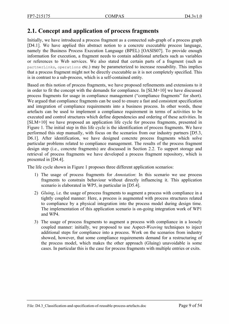
Based on this notion of process fragments, we have proposed refinements and extensions to it in order to fit the concept with the demands for compliance. In [SLM+10] we have discussed process fragments for usage in compliance management (“compliance fragments” for short). We argued that compliance fragments can be used to ensure a fast and consistent specification and integration of compliance requirements into a business process. In other words, these artefacts can be used to implement a compliance requirement in terms of activities to be executed and control structures which define dependencies and ordering of these activities. In [SLM+10] we have proposed an application life cycle for process fragments, presented in Figure 1. The initial step in this life cycle is the identification of process fragments. We have performed this step manually, with focus on the scenarios from our industry partners [D5.3, D6.1]. After identification, we have designed concrete process fragments which solve particular problems related to compliance management. The results of the process fragment design step (i.e., concrete fragments) are discussed in Section 2.2. To support storage and retrieval of process fragments we have developed a process fragment repository, which is presented in [D4.4].
The life cycle shown in Figure 1 proposes three different application scenarios:
1) The usage of process fragments for Annotation: In this scenario we use process fragments to constrain behaviour without directly influencing it. This application scenario is elaborated in WP5, in particular in [D5.4].
2) Gluing, i.e. the usage of process fragments to augment a process with compliance in a tightly coupled manner: Here, a process is augmented with process structures related to compliance by a physical integration into the process model during design time. The implementation of this application scenario is on-going integration work of WP1 and WP4.
3) The usage of process fragments to augment a process with compliance in a loosely coupled manner: initially, we proposed to use Aspect-Weaving techniques to inject additional steps for compliance into a process. Work on the scenarios from industry showed, however, that some compliance requirements demand for a restructuring of the process model, which makes the other approach (Gluing) unavoidable is some cases. In particular this is the case for process fragments with multiple entries or exits.
FP7-215175 COMPAS D4.3v1.0
File: D4.3_Classification-and-specification-of-reusable-process-artefacts.doc Page 10 of 54
Figure 1 Process fragment life cycle [SLM+10]
We have further elaborated the process fragment concept and defined extension to BPEL in [D4.2]. This work provides the technical support for the actual implementation of the process fragment concept for an executable process language. These extensions include constructs to represent multiple entries and exits, activity placeholders (so-called regions), the fragment context (variables, handlers etc.), and unique identifiers to support annotations and traceability.
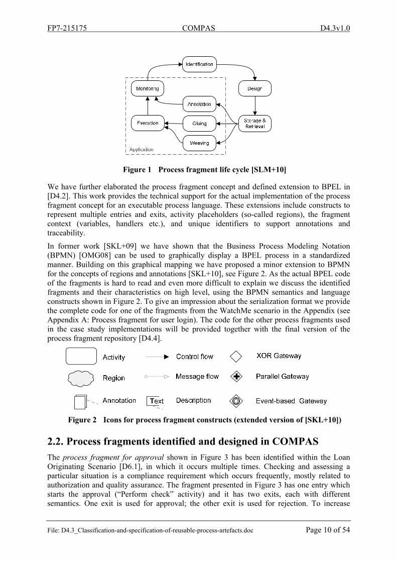
In former work [SKL+09] we have shown that the Business Process Modeling Notation (BPMN) [OMG08] can be used to graphically display a BPEL process in a standardized manner. Building on this graphical mapping we have proposed a minor extension to BPMN for the concepts of regions and annotations [SKL+10], see Figure 2. As the actual BPEL code of the fragments is hard to read and even more difficult to explain we discuss the identified fragments and their characteristics on high level, using the BPMN semantics and language constructs shown in Figure 2. To give an impression about the serialization format we provide the complete code for one of the fragments from the WatchMe scenario in the Appendix (see Appendix A: Process fragment for user login). The code for the other process fragments used in the case study implementations will be provided together with the final version of the process fragment repository [D4.4].
Figure 2 Icons for process fragment constructs (extended version of [SKL+10])
2.2. Process fragments identified and designed in COMPAS
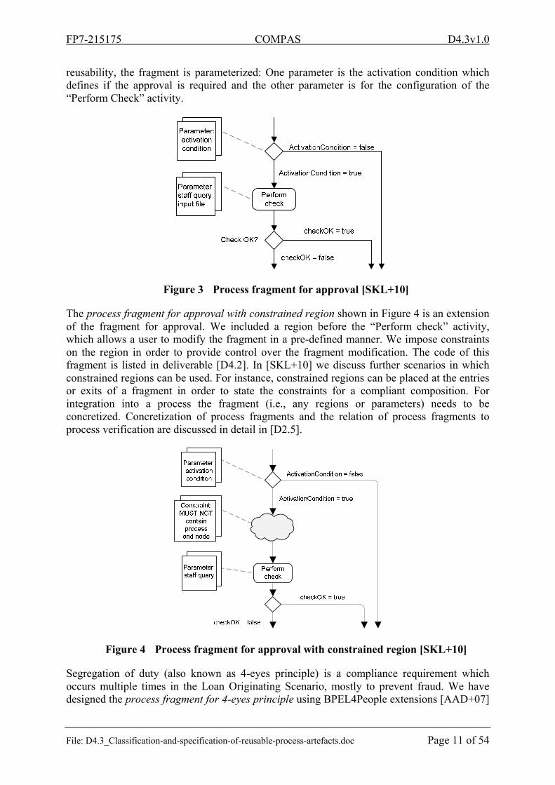
The process fragment for approval shown in Figure 3 has been identified within the Loan Originating Scenario [D6.1], in which it occurs multiple times. Checking and assessing a particular situation is a compliance requirement which occurs frequently, mostly related to authorization and quality assurance. The fragment presented in Figure 3 has one entry which starts the approval (“Perform check” activity) and it has two exits, each with different semantics. One exit is used for approval; the other exit is used for rejection. To increase
FP7-215175 COMPAS D4.3v1.0
File: D4.3_Classification-and-specification-of-reusable-process-artefacts.doc Page 11 of 54
reusability, the fragment is parameterized: One parameter is the activation condition which defines if the approval is required and the other parameter is for the configuration of the “Perform Check” activity.
Figure 3 Process fragment for approval [SKL+10]
The process fragment for approval with constrained region shown in Figure 4 is an extension of the fragment for approval. We included a region before the “Perform check” activity, which allows a user to modify the fragment in a pre-defined manner. We impose constraints on the region in order to provide control over the fragment modification. The code of this fragment is listed in deliverable [D4.2]. In [SKL+10] we discuss further scenarios in which constrained regions can be used. For instance, constrained regions can be placed at the entries or exits of a fragment in order to state the constraints for a compliant composition. For integration into a process the fragment (i.e., any regions or parameters) needs to be concretized. Concretization of process fragments and the relation of process fragments to process verification are discussed in detail in [D2.5].
Figure 4 Process fragment for approval with constrained region [SKL+10]
Segregation of duty (also known as 4-eyes principle) is a compliance requirement which occurs multiple times in the Loan Originating Scenario, mostly to prevent fraud. We have designed the process fragment for 4-eyes principle using BPEL4People extensions [AAD+07]
FP7-215175 COMPAS D4.3v1.0
File: D4.3_Classification-and-specification-of-reusable-process-artefacts.doc Page 12 of 54
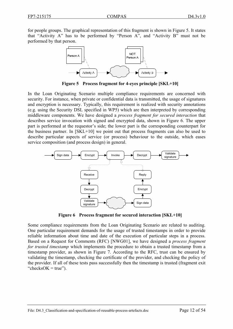
for people groups. The graphical representation of this fragment is shown in Figure 5. It states that “Activity A” has to be performed by “Person A”, and “Activity B” must not be performed by that person.
Figure 5 Process fragment for 4-eyes principle [SKL+10]
In the Loan Originating Scenario multiple compliance requirements are concerned with security. For instance, when private or confidential data is transmitted, the usage of signatures and encryption is necessary. Typically, this requirement is realized with security annotations (e.g. using the Security DSL specified in WP5) which are then interpreted by corresponding middleware components. We have designed a process fragment for secured interaction that describes service invocation with signed and encrypted data, shown in Figure 6. The upper part is performed at the requestor’s side; the lower part is the corresponding counterpart for the business partner. In [SKL+10] we point out that process fragments can also be used to describe particular aspects of service (or process) behaviour to the outside, which eases service composition (and process design) in general.
Sign data Encrypt Invoke DecryptValidatesignature
Receive
Decrypt
Validate signature Sign data
Encrypt
Reply
Figure 6 Process fragment for secured interaction [SKL+10]
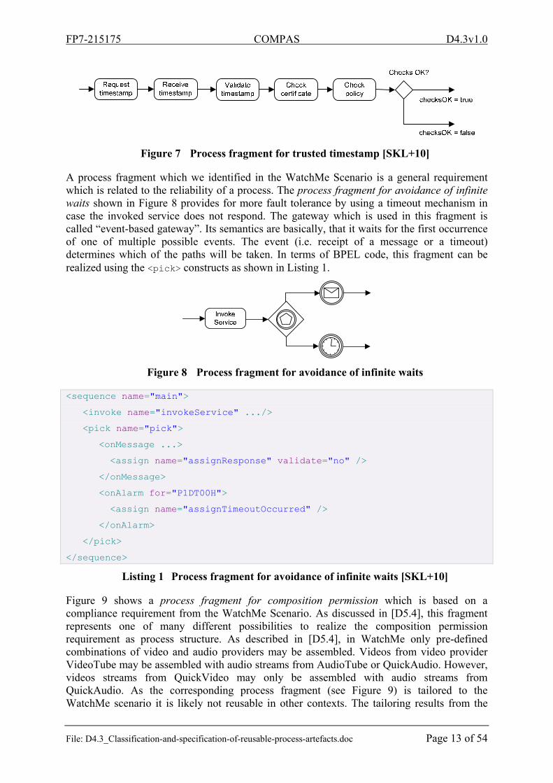
Some compliance requirements from the Loan Originating Scenario are related to auditing. One particular requirement demands for the usage of trusted timestamps in order to provide reliable information about time and date of the execution of particular steps in a process. Based on a Request for Comments (RFC) [NWG01], we have designed a process fragment for trusted timestamp which implements the procedure to obtain a trusted timestamp from a timestamp provider, as shown in Figure 7. According to the RFC, trust can be ensured by validating the timestamp, checking the certificate of the provider, and checking the policy of the provider. If all of these tests pass successfully then the timestamp is trusted (fragment exit “checksOK = true”).
FP7-215175 COMPAS D4.3v1.0
File: D4.3_Classification-and-specification-of-reusable-process-artefacts.doc Page 13 of 54
Figure 7 Process fragment for trusted timestamp [SKL+10]
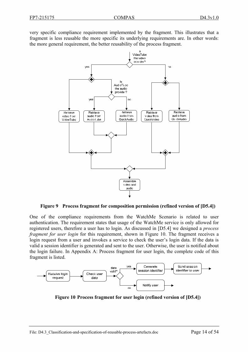
A process fragment which we identified in the WatchMe Scenario is a general requirement which is related to the reliability of a process. The process fragment for avoidance of infinite waits shown in Figure 8 provides for more fault tolerance by using a timeout mechanism in case the invoked service does not respond. The gateway which is used in this fragment is called “event-based gateway”. Its semantics are basically, that it waits for the first occurrence of one of multiple possible events. The event (i.e. receipt of a message or a timeout) determines which of the paths will be taken. In terms of BPEL code, this fragment can be realized using the <pick> constructs as shown in Listing 1.
Figure 8 Process fragment for avoidance of infinite waits
<sequence name="main">
<invoke name="invokeService" .../>
<pick name="pick">
<onMessage ...>
<assign name="assignResponse" validate="no" />
</onMessage>
<onAlarm for="P1DT00H">
<assign name="assignTimeoutOccurred" />
</onAlarm>
</pick>
</sequence>
Listing 1 Process fragment for avoidance of infinite waits [SKL+10]
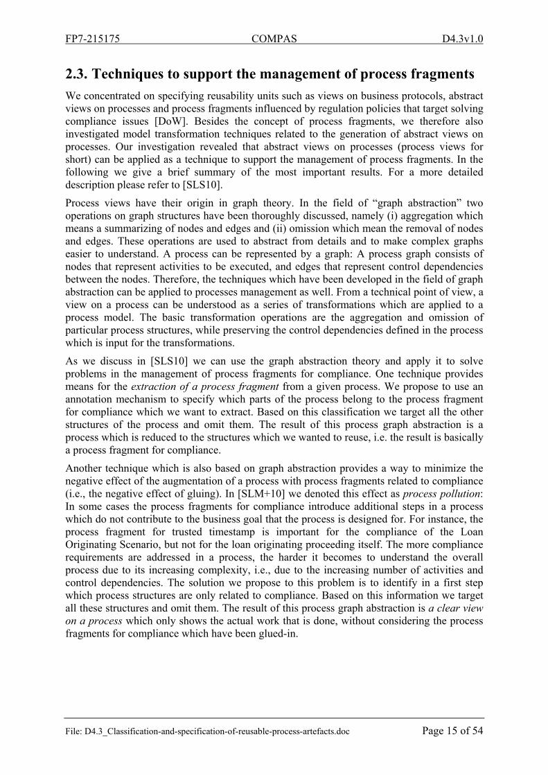
Figure 9 shows a process fragment for composition permission which is based on a compliance requirement from the WatchMe Scenario. As discussed in [D5.4], this fragment represents one of many different possibilities to realize the composition permission requirement as process structure. As described in [D5.4], in WatchMe only pre-defined combinations of video and audio providers may be assembled. Videos from video provider VideoTube may be assembled with audio streams from AudioTube or QuickAudio. However, videos streams from QuickVideo may only be assembled with audio streams from QuickAudio. As the corresponding process fragment (see Figure 9) is tailored to the WatchMe scenario it is likely not reusable in other contexts. The tailoring results from the
FP7-215175 COMPAS D4.3v1.0
File: D4.3_Classification-and-specification-of-reusable-process-artefacts.doc Page 14 of 54
very specific compliance requirement implemented by the fragment. This illustrates that a fragment is less reusable the more specific its underlying requirements are. In other words: the more general requirement, the better reusability of the process fragment.
Figure 9 Process fragment for composition permission (refined version of [D5.4])
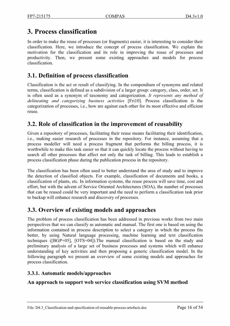
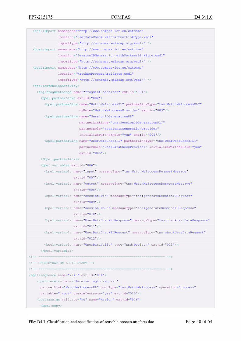
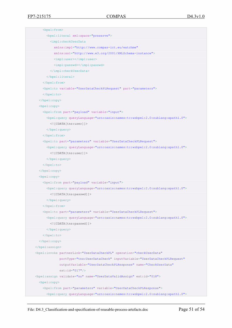
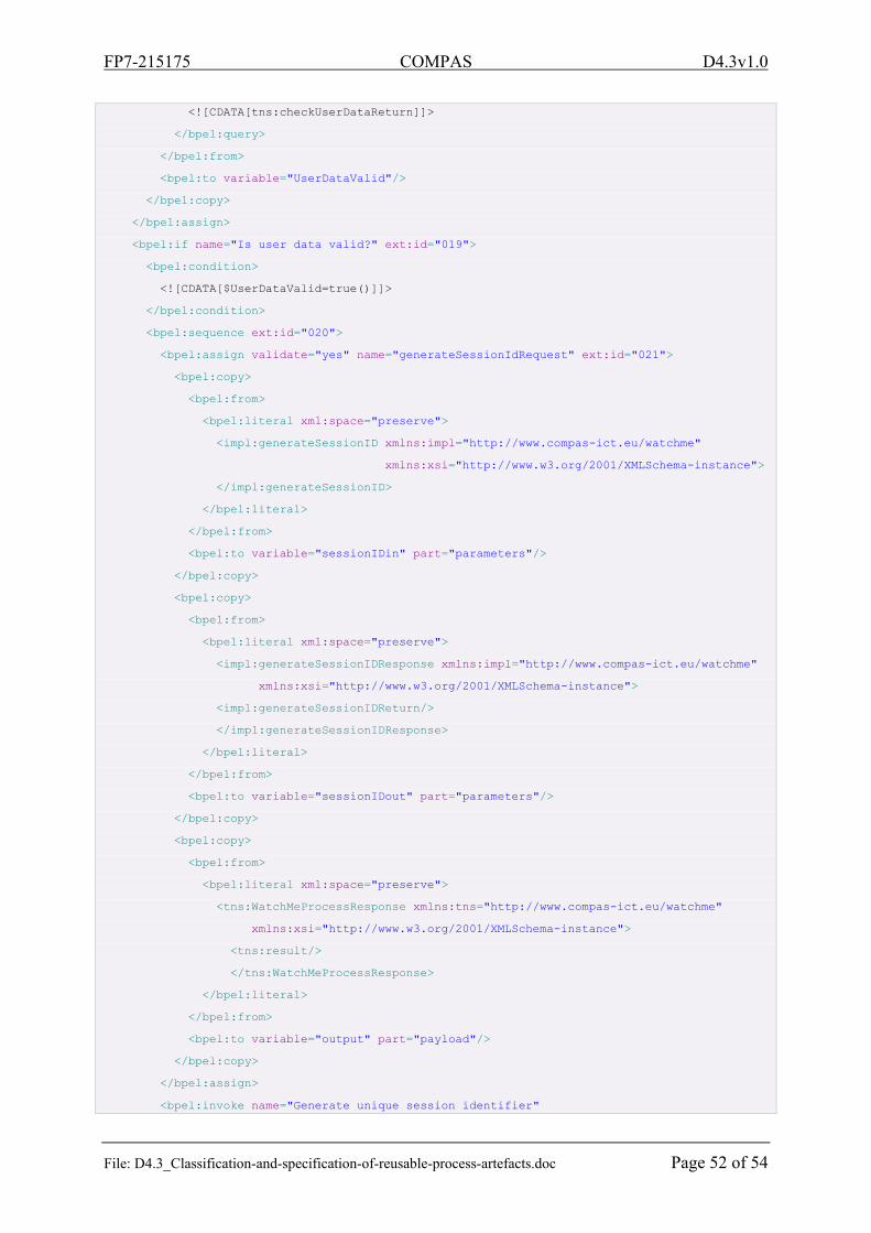
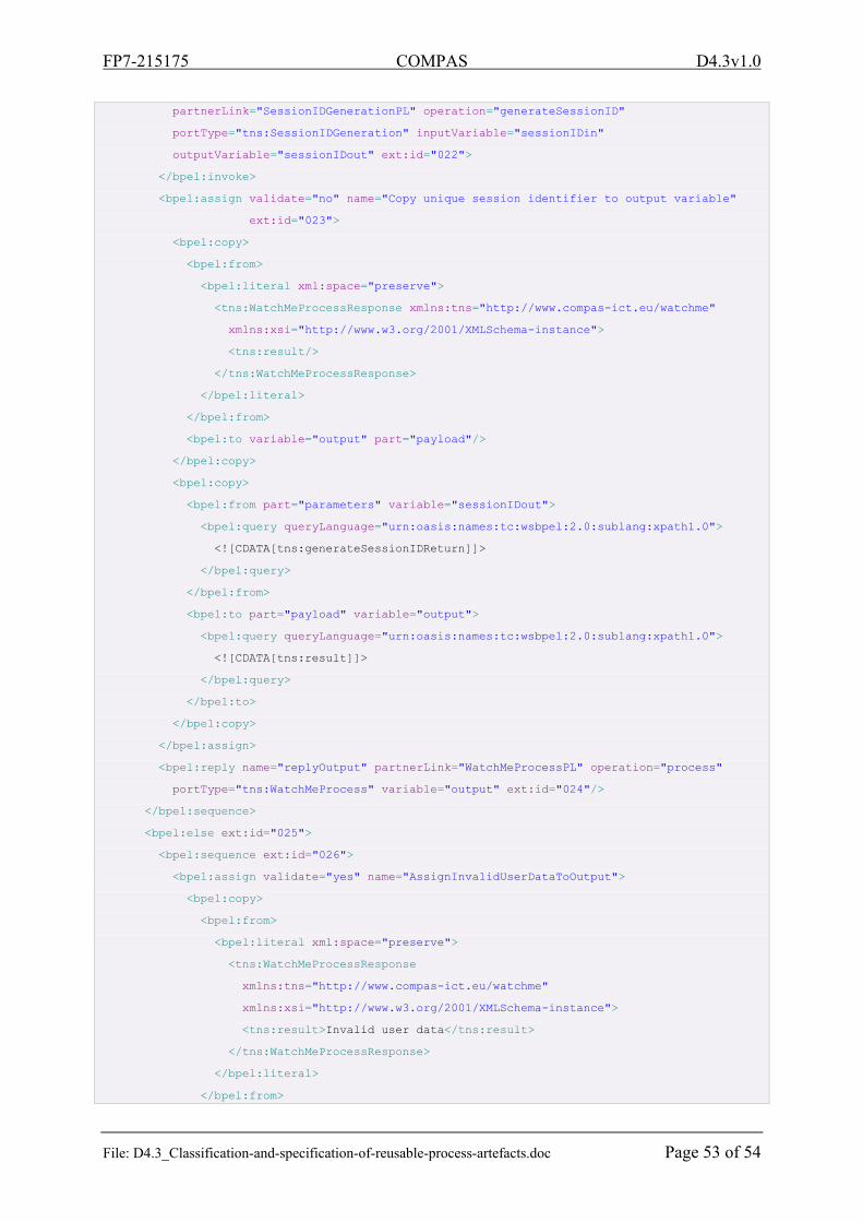
One of the compliance requirements from the WatchMe Scenario is related to user authentication. The requirement states that usage of the WatchMe service is only allowed for registered users, therefore a user has to login. As discussed in [D5.4] we designed a process fragment for user login for this requirement, shown in Figure 10. The fragment receives a login request from a user and invokes a service to check the user’s login data. If the data is valid a session identifier is generated and sent to the user. Otherwise, the user is notified about the login failure. In Appendix A: Process fragment for user login, the complete code of this fragment is listed.
Figure 10 Process fragment for user login (refined version of [D5.4])
FP7-215175 COMPAS D4.3v1.0
File: D4.3_Classification-and-specification-of-reusable-process-artefacts.doc Page 15 of 54
2.3. Techniques to support the management of process fragments
We concentrated on specifying reusability units such as views on business protocols, abstract views on processes and process fragments influenced by regulation policies that target solving compliance issues [DoW]. Besides the concept of process fragments, we therefore also investigated model transformation techniques related to the generation of abstract views on processes. Our investigation revealed that abstract views on processes (process views for short) can be applied as a technique to support the management of process fragments. In the following we give a brief summary of the most important results. For a more detailed description please refer to [SLS10].
Process views have their origin in graph theory. In the field of “graph abstraction” two operations on graph structures have been thoroughly discussed, namely (i) aggregation which means a summarizing of nodes and edges and (ii) omission which mean the removal of nodes and edges. These operations are used to abstract from details and to make complex graphs easier to understand. A process can be represented by a graph: A process graph consists of nodes that represent activities to be executed, and edges that represent control dependencies between the nodes. Therefore, the techniques which have been developed in the field of graph abstraction can be applied to processes management as well. From a technical point of view, a view on a process can be understood as a series of transformations which are applied to a process model. The basic transformation operations are the aggregation and omission of particular process structures, while preserving the control dependencies defined in the process which is input for the transformations.
As we discuss in [SLS10] we can use the graph abstraction theory and apply it to solve problems in the management of process fragments for compliance. One technique provides means for the extraction of a process fragment from a given process. We propose to use an annotation mechanism to specify which parts of the process belong to the process fragment for compliance which we want to extract. Based on this classification we target all the other structures of the process and omit them. The result of this process graph abstraction is a process which is reduced to the structures which we wanted to reuse, i.e. the result is basically a process fragment for compliance.
Another technique which is also based on graph abstraction provides a way to minimize the negative effect of the augmentation of a process with process fragments related to compliance (i.e., the negative effect of gluing). In [SLM+10] we denoted this effect as process pollution: In some cases the process fragments for compliance introduce additional steps in a process which do not contribute to the business goal that the process is designed for. For instance, the process fragment for trusted timestamp is important for the compliance of the Loan Originating Scenario, but not for the loan originating proceeding itself. The more compliance requirements are addressed in a process, the harder it becomes to understand the overall process due to its increasing complexity, i.e., due to the increasing number of activities and control dependencies. The solution we propose to this problem is to identify in a first step which process structures are only related to compliance. Based on this information we target all these structures and omit them. The result of this process graph abstraction is a clear view on a process which only shows the actual work that is done, without considering the process fragments for compliance which have been glued-in.
FP7-215175 COMPAS D4.3v1.0
File: D4.3_Classification-and-specification-of-reusable-process-artefacts.doc Page 16 of 54
3. Process classification In order to make the reuse of processes (or fragments) easier, it is interesting to consider their classification. Here, we introduce the concept of process classification. We explain the motivation for the classification and its role in improving the reuse of processes and productivity. Then, we present some existing approaches and models for process classification.
3.1. Definition of process classification
Classification is the act or result of classifying. In the compendium of synonyms and related terms, classification is defined as a subdivision of a larger group: category, class, order, set. It is often used as a synonym of taxonomy and categorization. It represents any method of delineating and categorizing business activities [Fri10]. Process classification is the categorization of processes, i.e., how are against each other for its most effective and efficient reuse.
3.2. Role of classification in the improvement of reusability
Given a repository of processes, facilitating their reuse means facilitating their identification, i.e., making easier research of processes in the repository. For instance, assuming that a process modeller will need a process fragment that performs the billing process, it is worthwhile to make this task easier so that it can quickly locate the process without having to search all other processes that affect not only the task of billing. This leads to establish a process classification phase during the publication process in the repository. The classification has been often used to better understand the area of study and to improve the detection of classified objects. For example, classification of documents and books, a classification of plants, etc. In information systems, the reuse process will save time, cost and effort, but with the advent of Service Oriented Architectures (SOA), the number of processes that can be reused could be very important and the need to perform a classification task prior to backup will enhance research and discovery of processes.
3.3. Overview of existing models and approaches
The problem of process classification has been addressed in previous works from two main perspectives that we can classify as automatic and manual. The first one is based on using the information contained in process description to select a category in which the process fits better, by using Natural language processing, machine learning and text classification techniques ([BGP+05], [OTS+04]).The manual classification is based on the study and preliminary analysis of a large set of business processes and systems which will enhance understanding of key activities and then proposing a generic classification model. In the following paragraph we present an overview of some existing models and approaches for process classification.
3.3.1. Automatic models/approaches
An approach to support web service classification using SVM method
FP7-215175 COMPAS D4.3v1.0
File: D4.3_Classification-and-specification-of-reusable-process-artefacts.doc Page 17 of 54
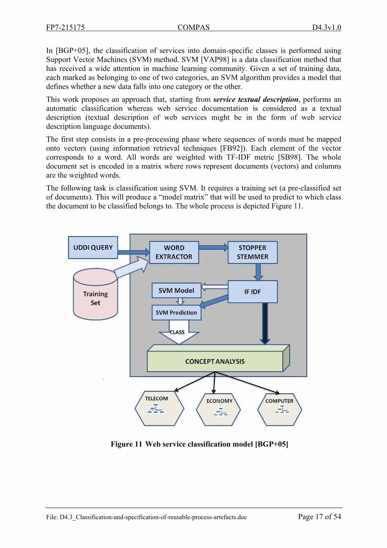
In [BGP+05], the classification of services into domain-specific classes is performed using Support Vector Machines (SVM) method. SVM [VAP98] is a data classification method that has received a wide attention in machine learning community. Given a set of training data, each marked as belonging to one of two categories, an SVM algorithm provides a model that defines whether a new data falls into one category or the other.
This work proposes an approach that, starting from service textual description, performs an automatic classification whereas web service documentation is considered as a textual description (textual description of web services might be in the form of web service description language documents).
The first step consists in a pre-processing phase where sequences of words must be mapped onto vectors (using information retrieval techniques [FB92]). Each element of the vector corresponds to a word. All words are weighted with TF-IDF metric [SB98]. The whole document set is encoded in a matrix where rows represent documents (vectors) and columns are the weighted words.
The following task is classification using SVM. It requires a training set (a pre-classified set of documents). This will produce a “model matrix” that will be used to predict to which class the document to be classified belongs to. The whole process is depicted Figure 11.
Figure 11 Web service classification model [BGP+05]
FP7-215175 COMPAS D4.3v1.0
File: D4.3_Classification-and-specification-of-reusable-process-artefacts.doc Page 18 of 54
Naïve Bayes Classifier for Web Service Classification
In [OTS+04], the authors use a machine learning approach (the Naïve Bayes Classifier) to predict the domain a particular Web service belongs to. The classifier determines the probability that a service belongs to a category by taking the product of the probabilities of each single word belonging to this category. The motivation of the authors is that “Naïve Bayes Classifiers have quadratic time complexity during the training phase and linear complexity for domain prediction, making this approach highly scalable”. Furthermore, these classifiers have been successfully deployed in text classification tasks, even though the independence assumption for distinct features that the classifier makes is clearly violated in natural language, where the context of a word in a sentence is actually quite important. The authors use as features method names and the argument names to classify the WSDL descriptions into domains, for which they can assume contextual independence, which renders the Naïve Bayes an ideal classifier. A WSDL description is represented as input to the classifier by a feature vector. Each feature represents the frequency of a particular word in the corresponding WSDL file. The position of the word is determined a priori, by parsing all WSDL files and building a dictionary of all the words used in the corpus of WSDL files. Each word has thus a unique ID which corresponds to its position in the feature vector. We use two different measures for word frequency. The first is the raw number of occurrences of a word in the description; the second is a TF-IDF representation [SB98] of this raw frequency.
Web service classification using traditional text-mining algorithms
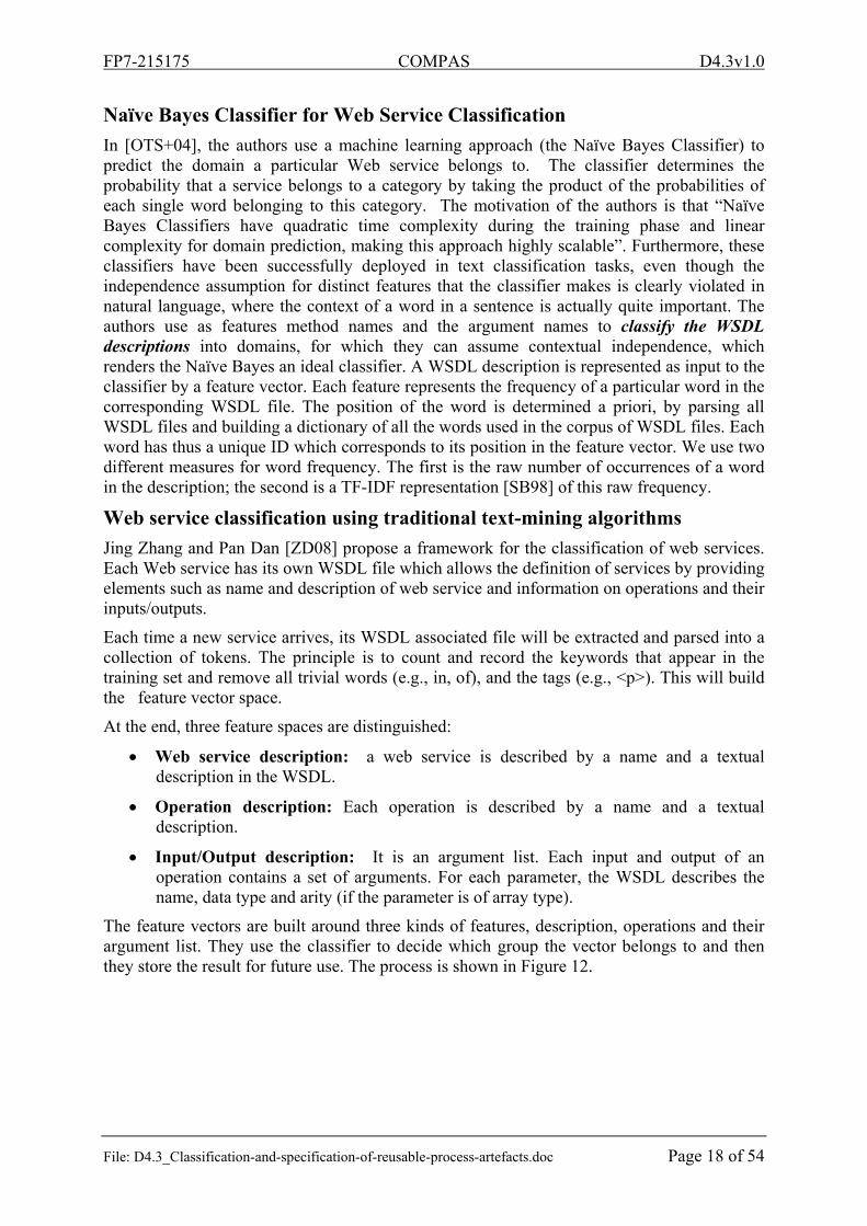
Jing Zhang and Pan Dan [ZD08] propose a framework for the classification of web services. Each Web service has its own WSDL file which allows the definition of services by providing elements such as name and description of web service and information on operations and their inputs/outputs.
Each time a new service arrives, its WSDL associated file will be extracted and parsed into a collection of tokens. The principle is to count and record the keywords that appear in the training set and remove all trivial words (e.g., in, of), and the tags (e.g., <p>). This will build the feature vector space.
At the end, three feature spaces are distinguished:
Web service description: a web service is described by a name and a textual description in the WSDL.
Operation description: Each operation is described by a name and a textual description.
Input/Output description: It is an argument list. Each input and output of an operation contains a set of arguments. For each parameter, the WSDL describes the name, data type and arity (if the parameter is of array type).
The feature vectors are built around three kinds of features, description, operations and their argument list. They use the classifier to decide which group the vector belongs to and then they store the result for future use. The process is shown in Figure 12.
FP7-215175 COMPAS D4.3v1.0
File: D4.3_Classification-and-specification-of-reusable-process-artefacts.doc Page 19 of 54
Figure 12 Model architecture [ZP06]
3.3.2. Manual models
A taxonomy of business processes
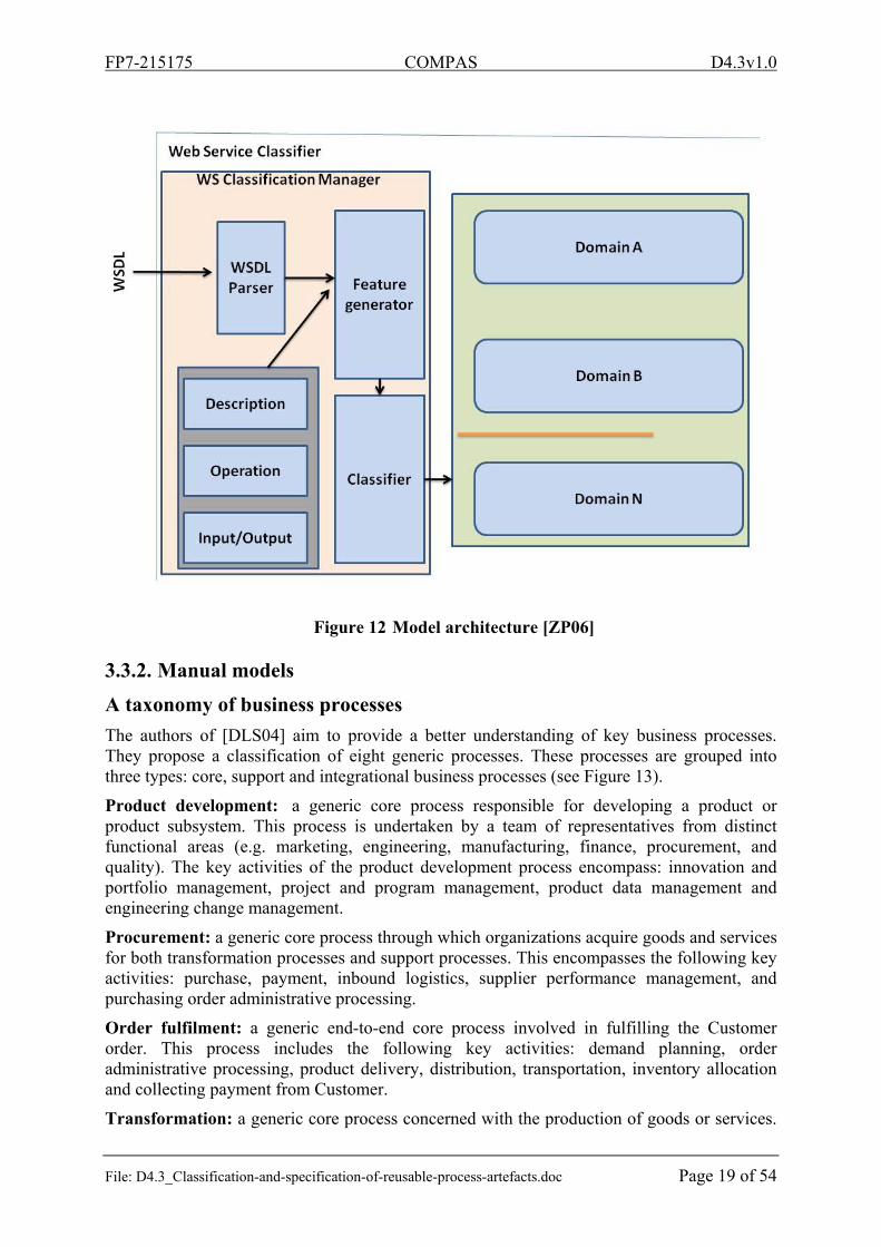
The authors of [DLS04] aim to provide a better understanding of key business processes. They propose a classification of eight generic processes. These processes are grouped into three types: core, support and integrational business processes (see Figure 13).
Product development: a generic core process responsible for developing a product or product subsystem. This process is undertaken by a team of representatives from distinct functional areas (e.g. marketing, engineering, manufacturing, finance, procurement, and quality). The key activities of the product development process encompass: innovation and portfolio management, project and program management, product data management and engineering change management.
Procurement: a generic core process through which organizations acquire goods and services for both transformation processes and support processes. This encompasses the following key activities: purchase, payment, inbound logistics, supplier performance management, and purchasing order administrative processing.
Order fulfilment: a generic end-to-end core process involved in fulfilling the Customer order. This process includes the following key activities: demand planning, order administrative processing, product delivery, distribution, transportation, inventory allocation and collecting payment from Customer.
Transformation: a generic core process concerned with the production of goods or services.
FP7-215175 COMPAS D4.3v1.0
File: D4.3_Classification-and-specification-of-reusable-process-artefacts.doc Page 20 of 54
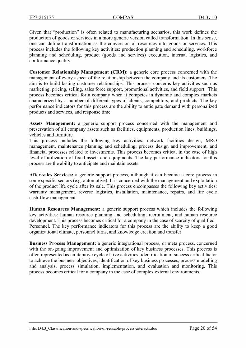
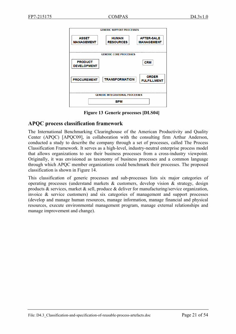
Given that “production” is often related to manufacturing scenarios, this work defines the production of goods or services in a more generic version called transformation. In this sense, one can define transformation as the conversion of resources into goods or services. This process includes the following key activities: production planning and scheduling, workforce planning and scheduling, product (goods and services) execution, internal logistics, and conformance quality. Customer Relationship Management (CRM): a generic core process concerned with the management of every aspect of the relationship between the company and its customers. The aim is to build lasting customer relationships. This process concerns key activities such as marketing, pricing, selling, sales force support, promotional activities, and field support. This process becomes critical for a company when it competes in dynamic and complex markets characterized by a number of different types of clients, competitors, and products. The key performance indicators for this process are the ability to anticipate demand with personalized products and services, and response time. Assets Management: a generic support process concerned with the management and preservation of all company assets such as facilities, equipments, production lines, buildings, vehicles and furniture. This process includes the following key activities: network facilities design, MRO management, maintenance planning and scheduling, process design and improvement, and financial processes related to investments. This process becomes critical in the case of high level of utilization of fixed assets and equipments. The key performance indicators for this process are the ability to anticipate and maintain assets. After-sales Services: a generic support process, although it can become a core process in some specific sectors (e.g. automotive). It is concerned with the management and exploitation of the product life cycle after its sale. This process encompasses the following key activities: warranty management, reverse logistics, installation, maintenance, repairs, and life cycle cash-flow management. Human Resources Management: a generic support process which includes the following key activities: human resource planning and scheduling, recruitment, and human resource development. This process becomes critical for a company in the case of scarcity of qualified Personnel. The key performance indicators for this process are the ability to keep a good organizational climate, personnel turns, and knowledge creation and transfer Business Process Management: a generic integrational process, or meta process, concerned with the on-going improvement and optimization of key business processes. This process is often represented as an iterative cycle of five activities: identification of success critical factor to achieve the business objectives, identification of key business processes, process modelling and analysis, process simulation, implementation, and evaluation and monitoring. This process becomes critical for a company in the case of complex external environments.
FP7-215175 COMPAS D4.3v1.0
File: D4.3_Classification-and-specification-of-reusable-process-artefacts.doc Page 21 of 54
Figure 13 Generic processes [DLS04]
APQC process classification framework
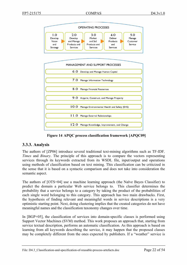
The International Benchmarking Clearinghouse of the American Productivity and Quality Center (APQC) [APQC09], in collaboration with the consulting firm Arthur Anderson, conducted a study to describe the company through a set of processes, called The Process Classification Framework. It serves as a high-level, industry-neutral enterprise process model that allows organizations to see their business processes from a cross-industry viewpoint. Originally, it was envisioned as taxonomy of business processes and a common language through which APQC member organizations could benchmark their processes. The proposed classification is shown in Figure 14.
This classification of generic processes and sub-processes lists six major categories of operating processes (understand markets & customers, develop vision & strategy, design products & services, market & sell, produce & deliver for manufacturing/service organization, invoice & service customers) and six categories of management and support processes (develop and manage human resources, manage information, manage financial and physical resources, execute environmental management program, manage external relationships and manage improvement and change).
FP7-215175 COMPAS D4.3v1.0
File: D4.3_Classification-and-specification-of-reusable-process-artefacts.doc Page 22 of 54
Figure 14 APQC process classification framework [APQC09]
3.3.3. Analysis
The authors of [ZP06] introduce several traditional text-mining algorithms such as TF-IDF, Times and Binary. The principle of this approach is to compare the vectors representing services through its keywords extracted from its WSDL file, input/output and operations using methods of classification based on text mining. This classification can be criticized in the sense that it is based on a syntactic comparison and does not take into consideration the semantic aspect. The authors of [OTS+04] use a machine learning approach (the Naïve Bayes Classifier) to predict the domain a particular Web service belongs to. This classifier determines the probability that a service belongs to a category by taking the product of the probabilities of each single word belonging to this category. This approach has two main drawbacks. First, the hypothesis of finding relevant and meaningful words in service descriptions is a very optimistic starting point. Next, doing clustering implies that the created categories do not have meaningful names and the classification taxonomy changes over time. In [BGP+05], the classification of services into domain-specific classes is performed using Support Vector Machines (SVM) method. This work proposes an approach that, starting from service textual description, performs an automatic classification. As this approach is based on learning from all keywords describing the service, it may happen that the proposed classes may be completely different from the ones expected by publishers. If a “weather” service is
FP7-215175 COMPAS D4.3v1.0
File: D4.3_Classification-and-specification-of-reusable-process-artefacts.doc Page 23 of 54
classified in the “finance” or “mail” domain, it means that the service description may be ambiguous. Hence, the service is never found by queries related to its own features.
Model/Approach Description Type
[BGP+05] Classification using SVM method Automatic
[OTS+04] Naïve Bayes classification for web service Automatic
[ZP06] Classification of web services using traditional text-mining algorithms
Automatic
[DLS04] Classification of eight generic processes grouped in three types : core, support and integrational business processes
Manual
[APQC09]
American productivity and quality process classification framework : Classification of six major categories of operating processes and six categories of management and support processes
Manual
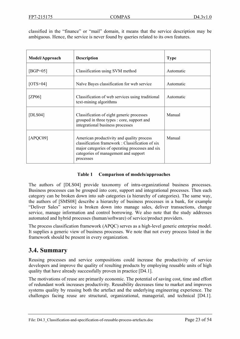
Table 1 Comparison of models/approaches
The authors of [DLS04] provide taxonomy of intra-organizational business processes. Business processes can be grouped into core, support and integrational processes. Then each category can be broken down into sub categories (a hierarchy of categories). The same way, the authors of [SMS08] describe a hierarchy of business processes in a bank, for example “Deliver Sales” service is broken down into manage sales, deliver transactions, change service, manage information and control borrowing. We also note that the study addresses automated and hybrid processes (human/software) of service/product providers.
The process classification framework (APQC) serves as a high-level generic enterprise model. It supplies a generic view of business processes. We note that not every process listed in the framework should be present in every organization.
3.4. Summary
Reusing processes and service compositions could increase the productivity of service developers and improve the quality of resulting products by employing reusable units of high quality that have already successfully proven in practice [D4.1].
The motivations of reuse are primarily economic. The potential of saving cost, time and effort of redundant work increases productivity. Reusability decreases time to market and improves systems quality by reusing both the artefact and the underlying engineering experience. The challenges facing reuse are structural, organizational, managerial, and technical [D4.1].
FP7-215175 COMPAS D4.3v1.0
File: D4.3_Classification-and-specification-of-reusable-process-artefacts.doc Page 24 of 54
Furthermore, the number of web services made available on the Internet becomes important. Therefore, mechanisms that enable organization and discovery of services become necessary.
4. Toward automatic business process fragmentation and classification
In this section, we will present a new approach that allows automatic fragmentation of a business process by using business rules expressed in linear temporal logic. Given a BPEL composition of web services, we want to determine the part of a process that contributes and ensure the verification of a given business rules. The set of business process fragments verifying a sub set of business rules are considered as belonging to the same class.
For instance, let us consider an example of a process of online purchase. The system is implemented as a complex composition of web services. The process is composed by a subset of features: payment, bidding, ordering … etc. We want to secure the payment process without affecting other functionality. It is interesting to determine the part of the payment that work on the whole process which can be very difficult when the process is complex. This can be seen as a fragmentation process by answering a question like "what part of the process in which money is received?”. Benefits of fragmentation are analysing and reusing. Another advantage is the simplicity that is in the update or the querying.
The presented approach in this section can be useful in the process of building new process fragments from existing process repository, which are classified according to the business rules that they verify.
Fragmentation [MDK+09] is the act of creating fragments out of one service composition by applying a fragmentation technique. A fragmentation technique is a method to perform fragmentation according to some fragmentation criteria. The fragmentation criteria may be described in natural language, e.g. “the resulting fragments group the activities according to who executes them”, or formally, for example using Category Theory. Fragmentation techniques combine the following two steps [MDK+09]:
(1) Fragment identification finds which elements belong to which fragment. (2) Fragment severing: removes the elements comprised in a fragment from the service
composition, possibly substituting them in the service composition with other elements that were not initially included.
Current techniques of fragmentation can be divided into two classes: query languages for fragmentation and fragmentation for migration, optimality, transactionality and performance. A Query language for fragmentation groups slicing [Tip95], LTL [Eme91], BPQL [BEK+05] and goal oriented fragment [NC04]. The problem is that current approaches are not business oriented. They are not based on real temporal query languages. Fragmentation is generally used for migration and performance, the fragment is not determined regarding business rules and in general, they return execution traces instead of part of the process. To address these limitations, we proposed a new approach to produce fragment using business query, this query is based on temporal logic.
Our approach is based on model checking and attempt to define fragment model compositions of web services, the two contributions are:
(1) Proposal of a new approach of fragmentation based on business rules. The rules are specified in linear temporal logic based on the notion of causality and models checking.
(2) Refinement of a fragment and differentiate between two types of statements in a fragment.
FP7-215175 COMPAS D4.3v1.0
File: D4.3_Classification-and-specification-of-reusable-process-artefacts.doc Page 25 of 54
4.1. Preliminaries
4.1.1. Temporal logics
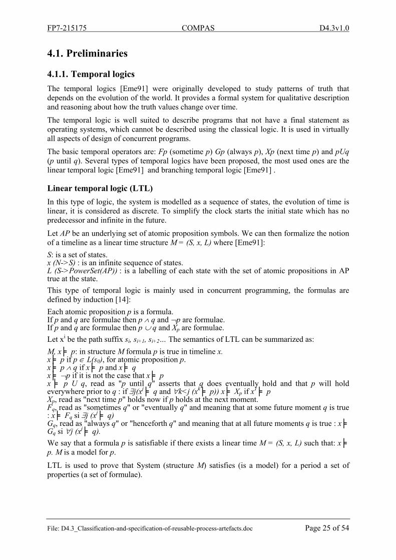
The temporal logics [Eme91] were originally developed to study patterns of truth that depends on the evolution of the world. It provides a formal system for qualitative description and reasoning about how the truth values change over time.
The temporal logic is well suited to describe programs that not have a final statement as operating systems, which cannot be described using the classical logic. It is used in virtually all aspects of design of concurrent programs.
The basic temporal operators are: Fp (sometime p) Gp (always p), Xp (next time p) and pUq (p until q). Several types of temporal logics have been proposed, the most used ones are the linear temporal logic [Eme91] and branching temporal logic [Eme91] .
Linear temporal logic (LTL)
In this type of logic, the system is modelled as a sequence of states, the evolution of time is linear, it is considered as discrete. To simplify the clock starts the initial state which has no predecessor and infinite in the future.
Let AP be an underlying set of atomic proposition symbols. We can then formalize the notion of a timeline as a linear time structure M = (S, x, L) where [Eme91]:
S: is a set of states. x (N->S) : is an infinite sequence of states. L (S->PowerSet(AP)) : is a labelling of each state with the set of atomic propositions in AP true at the state.
This type of temporal logic is mainly used in concurrent programming, the formulas are defined by induction [14]:
Each atomic proposition p is a formula. If p and q are formulae then p q and p are formulae. If p and q are formulae then p q and Xp are formulae.
Let xi be the path suffix si, si+1, si+2… The semantics of LTL can be summarized as:
M, x ╞ p: in structure M formula p is true in timeline x. x ╞ p if p L(s0), for atomic proposition p. x ╞ p q if x ╞ p and x ╞ q x ╞ p if it is not the case that x ╞ p x ╞ p U q, read as "p until q" asserts that q does eventually hold and that p will hold everywhere prior to q : if j(xj ╞ q and k<j (xk ╞ p)) x ╞ Xp if x
1 ╞ p Xp, read as "next time p" holds now if p holds at the next moment. Fq, read as "sometimes q" or "eventually q" and meaning that at some future moment q is true : x ╞ Fq si j (xj ╞ q) Gq, read as "always q" or "henceforth q" and meaning that at all future moments q is true : x ╞ Gq si j (xj ╞ q).
We say that a formula p is satisfiable if there exists a linear time M = (S, x, L) such that: x ╞ p. M is a model for p.
LTL is used to prove that System (structure M) satisfies (is a model) for a period a set of properties (a set of formulae).
FP7-215175 COMPAS D4.3v1.0
File: D4.3_Classification-and-specification-of-reusable-process-artefacts.doc Page 26 of 54
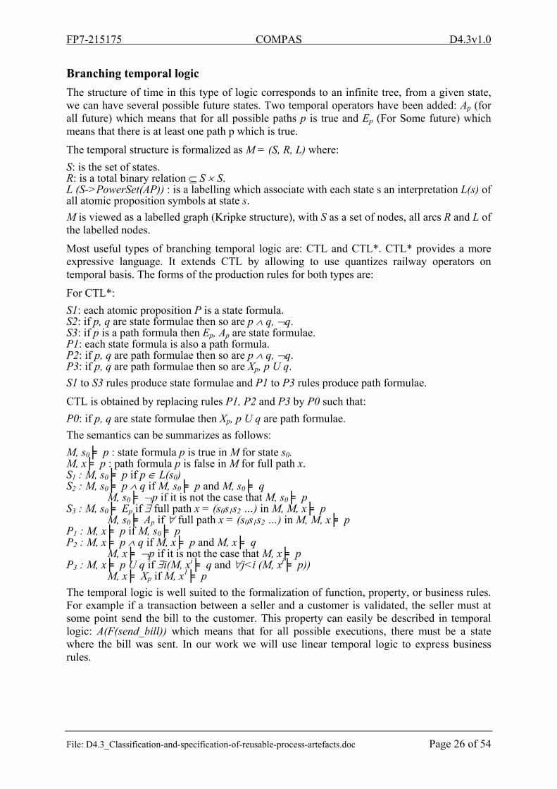
Branching temporal logic
The structure of time in this type of logic corresponds to an infinite tree, from a given state, we can have several possible future states. Two temporal operators have been added: Ap (for all future) which means that for all possible paths p is true and Ep (For Some future) which means that there is at least one path p which is true.
The temporal structure is formalized as M = (S, R, L) where:
S: is the set of states. R: is a total binary relation S S. L (S->PowerSet(AP)) : is a labelling which associate with each state s an interpretation L(s) of all atomic proposition symbols at state s.
M is viewed as a labelled graph (Kripke structure), with S as a set of nodes, all arcs R and L of the labelled nodes.
Most useful types of branching temporal logic are: CTL and CTL*. CTL* provides a more expressive language. It extends CTL by allowing to use quantizes railway operators on temporal basis. The forms of the production rules for both types are:
For CTL*:
S1: each atomic proposition P is a state formula. S2: if p, q are state formulae then so are p q, q. S3: if p is a path formula then Ep, Ap are state formulae. P1: each state formula is also a path formula. P2: if p, q are path formulae then so are p q, q. P3: if p, q are path formulae then so are Xp, p U q.
S1 to S3 rules produce state formulae and P1 to P3 rules produce path formulae.
CTL is obtained by replacing rules P1, P2 and P3 by P0 such that:
P0: if p, q are state formulae then Xp, p U q are path formulae.
The semantics can be summarizes as follows:
M, s0 ╞ p : state formula p is true in M for state s0. M, x ╞ p : path formula p is false in M for full path x. S1 : M, s0 ╞ p if p L(s0) S2 : M, s0 ╞ p q if M, s0 ╞ p and M, s0 ╞ q
M, s0 ╞ p if it is not the case that M, s0 ╞ p S3 : M, s0 ╞ Ep if full path x = (s0s1s2 …) in M, M, x ╞ p
M, s0 ╞ Ap if full path x = (s0s1s2 …) in M, M, x ╞ p P1 : M, x ╞ p if M, s0 ╞ p P2 : M, x ╞ p q if M, x ╞ p and M, x ╞ q
M, x ╞ p if it is not the case that M, x ╞ p P3 : M, x ╞ p U q if i(M, xi ╞ q and j<i (M, xj ╞ p))
M, x ╞ Xp if M, x1 ╞ p
The temporal logic is well suited to the formalization of function, property, or business rules. For example if a transaction between a seller and a customer is validated, the seller must at some point send the bill to the customer. This property can easily be described in temporal logic: A(F(send_bill)) which means that for all possible executions, there must be a state where the bill was sent. In our work we will use linear temporal logic to express business rules.
FP7-215175 COMPAS D4.3v1.0
File: D4.3_Classification-and-specification-of-reusable-process-artefacts.doc Page 27 of 54
Formalization of business rules with LTL
A business rule [BRG00] is an assertion that defines an aspect of business. We are interested in this work to a subset of business rules, the rules expressible in LTL [ETV+10, HPH10]. The advantage of using LTL is that much of business rules are based on time which is taken in consideration by the temporal logic. One can for example express business rules of type "delivery of the product should not exceed two days" by "F(period_exceedproduct_delivery)".
Business rules can be expressed in LTL in many ways, for example for the previous rule, it can be formalized in a different way "period_exceedU(product_deliveryperiod_exceed)". The way to express the business rule LTL can have a direct impact on the size of the fragment. In our example, second formalization is more expressive than the first. Therefore the size of the fragment of the first formalism is smaller than in the second. This can be justified by an existing hidden property considered as true. This means we can’t have a “false true false” sequence for value of “period_exceed”. It is obvious that this property is true for all systems, but imagines for example if the property is “account>0” in failing system. This may lead us to errors. We want just to highlight the expressed manner of business rules is a very important fragmentation factor.
4.1.2. Model Checking
The problem of model checking [CGP99] is to check whether a temporal structure M defines a model for a temporal formula p. This problem is decidable for most temporal logic formula, in the worst case we precede by a full search. The model checking can create interesting applications for automated verification of concurrent systems.
Model checkers typically have three main components: (1) a specification language, based on propositional temporal logic, (2) a way of encoding a state machine representing the system to be verified, and (3) a verification procedure, that uses an intelligent exhaustive search of the state space to determine if the specification is true or not. If the specification is not satisfied, then most model checkers will produce a counterexample execution trace that shows why the specification does not hold. It is impossible to overestimate the importance of this feature. The counterexamples are invaluable in debugging complex systems [CES09].
There are three main families of model checking algorithm: Symbolic Model Checking with ordered binary decision diagrams (OBDDs), Partial Order Reduction and Bounded Model Checking with SAT. Detail can be found in [CES09].
Several model checkers have been developed. Examples are: NuSMV which is a symbolic model checker, and SPIN which is a partial order reduction model checker. In this work, we will use the Spin model checker [Hol04] which is more appropriate for concurrent systems [KPR04]. Spin [Hol97] is in the family of Partial Order Reduction model checker.
The specification language underlying SPIN is called PROMELA. The name SPIN was originally chosen as an acronym for Simple PROMELA Interpreter. PROMELA is a specification language for parallel asynchronous systems. It allows describing concurrent systems, especially communication protocols.
4.1.3. Verification of web service
The general principle of the work done in the verification of compositions of Web services is the abstraction of the latter in a formal model, then from such an abstraction to the language of the chosen model checker. The well-known model checkers are SPIN and NuSMV.
FP7-215175 COMPAS D4.3v1.0
File: D4.3_Classification-and-specification-of-reusable-process-artefacts.doc Page 28 of 54
NuSMV model checker is more efficient than SPIN [KPR04], but not adapted to concurrent process. We use SPIN as a model checker because it is more oriented to concurrent systems.
Among the projects undertaken in the field, we can cite the work of Zhao et al. [ZYQ06], who proposed a formal model for verification of choreography of web services. They translate choreography to orchestration then to PROMELA for using SPIN model checker. Fisteus et al. [AFK05] propose VERBUS, a framework consisting of three layers: layer process definition, common formal model layer which is based on a transition system, and a layer of verification. The advantage is that the verification is independent of the used model checker and process definition.
In [LQS+07] the authors propose a model based on multi-agent systems for verifying temporal and epistemic properties in a composition of web services. They use a special language of description system (ISPL), with a symbolic model checker (MCMAS) dedicated to Multi Agent Systems. They propose an approach to verification of the behaviour of a service and knowledge gained during the composition, in contrast to model checkers NuSMV and SPIN which are limited to the verification of temporal modality.
Fu et al. [FBS04] propose a model for the analysis of a BPEL composition of web services. Composition of web services is seen as a pattern of conversations between a set of peers. To each peer is associated a waiting list for message, and a guarded automata that specifies its individual conduct. They define a set of rules to move from BPEL composition to their automata model then from their model to a PROMELA specification. They use SPIN for verification. The authors also introduce the concept of synchronisability as a transformation of an asynchronous communication to a synchronous communication to facilitate verification. They propose a series of conditions that must be met to enable synchronisability. The authors have developed a tool that was used, it allows for the passage of a BPEL composition of web services to PROMELA specification.
4.1.4. Theorem proving
Theorem provers [Fis91, HKR+04, MP91, MP95] exist for linear temporal logic. However, since deciding satisfiability is P-space complete, this is in general not tractable. Model checking technics is theoretically also P-space complete, however efficient model checking tools as SPIN or NUSMV have been developed.
Spin is more convenient for concurrent system and is based on automata theory. At a first glance it appears that theorem proving is not convenient for our goal of explanation or fragmentation because of tractability issue. However recently, theorem proving gets new research interest because theorem proving tackles infinite state space system and is more and more used for producing counterexample [MZ09] and provide a real explanation [GP08]. Furthermore fragments of LTL have been shown [DFK06] to correspond to tractable case of model checking, and advent of efficient temporal resolution [HKR+04] tools tend to show that theorem proving has to be considered.
4.1.5. Slicing
A program slice consists of the parts of a program that (potentially) affects the values computed at some point of interest [Tip95]. Such a point of interest is referred to as a slicing criterion, and is typically specified by a location in the program in combination with a subset of the program’s variables. The task of computing program slices is called program slicing.
FP7-215175 COMPAS D4.3v1.0
File: D4.3_Classification-and-specification-of-reusable-process-artefacts.doc Page 29 of 54
A program slice S can be defined as a reduced, executable program obtained from a program P by removing statements, such that S replicates part of the behaviour of P. Another common definition of a slice is a subset of the statements and control predicates of the program that directly or indirectly affect the values computed at the criterion, but that do not necessarily constitute an executable program. An important distinction is that between a static and a dynamic slice. The former is computed without making assumptions’ regarding a program’s input, whereas the latter relies on some specific test case [Tip95].
Nanda et al. [NR00] formally defined the slicing in concurrent systems and propose an algorithm for slicing a concurrent program. They extend the classical models of representation to address new emerging types of dependence in parallelism. The authors propose optimizations to be done to prevent the complexity since it becomes exponential if the number of processes is large.
4.2. Fragmentation: state of the art and problem
Fragmentation is the act of creating a set of fragments from one service composition. Fragmentation techniques are procedure, algorithm or methodology to perform fragmentation according to predefined criteria in order to achieve a certain goal. Fragmentation techniques greatly differ in which types of process-based service compositions they are applicable to, why they are applied, how they define the fragments, etc. The state of the art lacks consistent terminology and definitions for the properties of the fragments of process-based service compositions and the criteria for classifying the different fragmentation techniques [MDK+09].
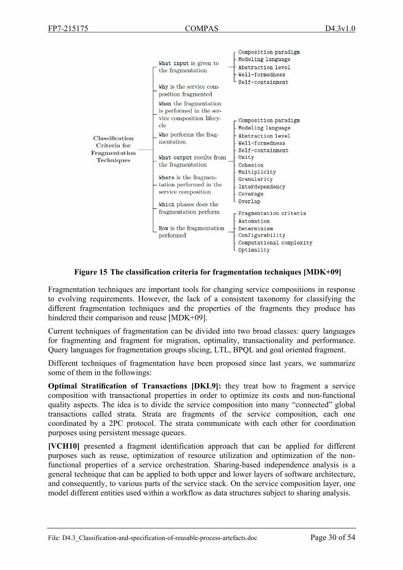
Mancioppi et al present in [MDK+09] criteria for classification techniques of fragmentation process based on web service composition. They are divided hierarchically in main and subcriteria, e.g. the main criterion what input is further specialized in Composition paradigm, Modeling language, Abstraction level, Well-formedness, and Self-containment. The classification is summarized in Figure 15.
FP7-215175 COMPAS D4.3v1.0
File: D4.3_Classification-and-specification-of-reusable-process-artefacts.doc Page 30 of 54
Figure 15 The classification criteria for fragmentation techniques [MDK+09]
Fragmentation techniques are important tools for changing service compositions in response to evolving requirements. However, the lack of a consistent taxonomy for classifying the different fragmentation techniques and the properties of the fragments they produce has hindered their comparison and reuse [MDK+09].
Current techniques of fragmentation can be divided into two broad classes: query languages for fragmenting and fragment for migration, optimality, transactionality and performance. Query languages for fragmentation groups slicing, LTL, BPQL and goal oriented fragment.
Different techniques of fragmentation have been proposed since last years, we summarize some of them in the followings:
Optimal Stratification of Transactions [DKL9]: they treat how to fragment a service composition with transactional properties in order to optimize its costs and non-functional quality aspects. The idea is to divide the service composition into many “connected” global transactions called strata. Strata are fragments of the service composition, each one coordinated by a 2PC protocol. The strata communicate with each other for coordination purposes using persistent message queues.
[VCH10] presented a fragment identification approach that can be applied for different purposes such as reuse, optimization of resource utilization and optimization of the non-functional properties of a service orchestration. Sharing-based independence analysis is a general technique that can be applied to both upper and lower layers of software architecture, and consequently, to various parts of the service stack. On the service composition layer, one model different entities used within a workflow as data structures subject to sharing analysis.
FP7-215175 COMPAS D4.3v1.0
File: D4.3_Classification-and-specification-of-reusable-process-artefacts.doc Page 31 of 54
[ZKM+09] propose an approach for fragmentation of the process instances that enables the decentralized execution of the process instance by several parties. The decentralized execution of business process instances is a promising approach for enabling flexible reactions to contextual changes at runtime. To do this, the work focuses on the runtime fragmentation of process instances, allowing several (potentially pre-selected) parties to execute a given process instance in a decentralized way. The main goal here is to enable a flexible adaptation of the responsibilities for the execution of the process (in whole or in part) to dynamically changing situations at runtime.
[ZHL10] presented an approach that supports the distributed parallel process execution with multiple mobile process participants. In case of a sequential execution of process fragments, the efforts of coordination can often be reduced to a (relatively simple) delegation resp. migration protocol. However, advanced synchronization and coordination mechanisms are required, if parallel process fragments have been distributed to several different parties. If, in addition, shared data objects are used in more than one of these parallel fragments, a separate execution could lead to undesired or wrong results. This contribution considers the concurrent execution of several parallel paths of the process instance by replication of the process description and respective execution of the parallel section of the process by different participants, including synchronization of control flow and data variables.
Khalaf [Kha08] has presented an automatic and operational semantics-preserving decomposition of business processes, in the presence of shared variables, loops, compensation, and fault handling. Their approach has been shown to be interoperable through the use of open standards, as well as transparent. It has also met the goal of not requiring new middleware unless loops and scopes are split, in which case, it requires extensions to existing middleware (i.e. BPEL engine and WS-Coordination framework).
Vanhatalo et al. [VVL07] proposed a technique to focus and speed up control-flow analysis of business process models that is based on decomposition into single-entry-single-exit (SESE) fragments. The SESE decomposition could also be used for other purposes such as browsing and constructing large processes, discovery of reusable subprocesses, code generation, and others. They also proposed a partition of the fragments into various categories, which can be computed fast. They think that tagging a fragment with its category may help to better understand the process model and may help to establish modeling patterns. It also helps to speed up the control-flow analysis as many of the correct fragments that occur in practice have a simple structure.
4.3. Proposition
The problem of the presented approaches in the precedent section is that they are not business oriented; they are not based on a real temporal query language. Fragmentation is generally used for migration and performance. The fragment is not determined regarding business rules and in general, the approaches return execution traces instead of part of the process.
4.3.1. Formalization
Given a web service composition expressed in BPEL, this composition can be an orchestration or choreography, our problem is to break down a web service composition based on a business rule expressed in LTL. That is to say, to find in the service composition a portion that contributes to the verification of the business rule.
FP7-215175 COMPAS D4.3v1.0
File: D4.3_Classification-and-specification-of-reusable-process-artefacts.doc Page 32 of 54
The part of the program that helps verify a given property is the cause of non-verification of the negation of the property. From this, the idea is to prove the non-verification of the negation of a business rule by the generation of a counterexample, then look for the causes of non-verification of the negation of business rule from this counterexample. The set of all the statements that led to these causes form the fragment.
It is easier to prove the non-satisfaction of a property (by the generation of a counterexample), than to prove the satisfaction of a property. Another advantage is the availability of tools for checking LTL formula. The LTL formulas are well suited to the formalization of some business rules because they treat the concept of time which is the foundation of most business rules.
We formalized our problem as a problem of causality that was introduced first by Halpern and Pearl [HP01]. We consider the problem of finding parts that contribute to the verification of a business rules as the one that causes the denial of falsifying business rules.
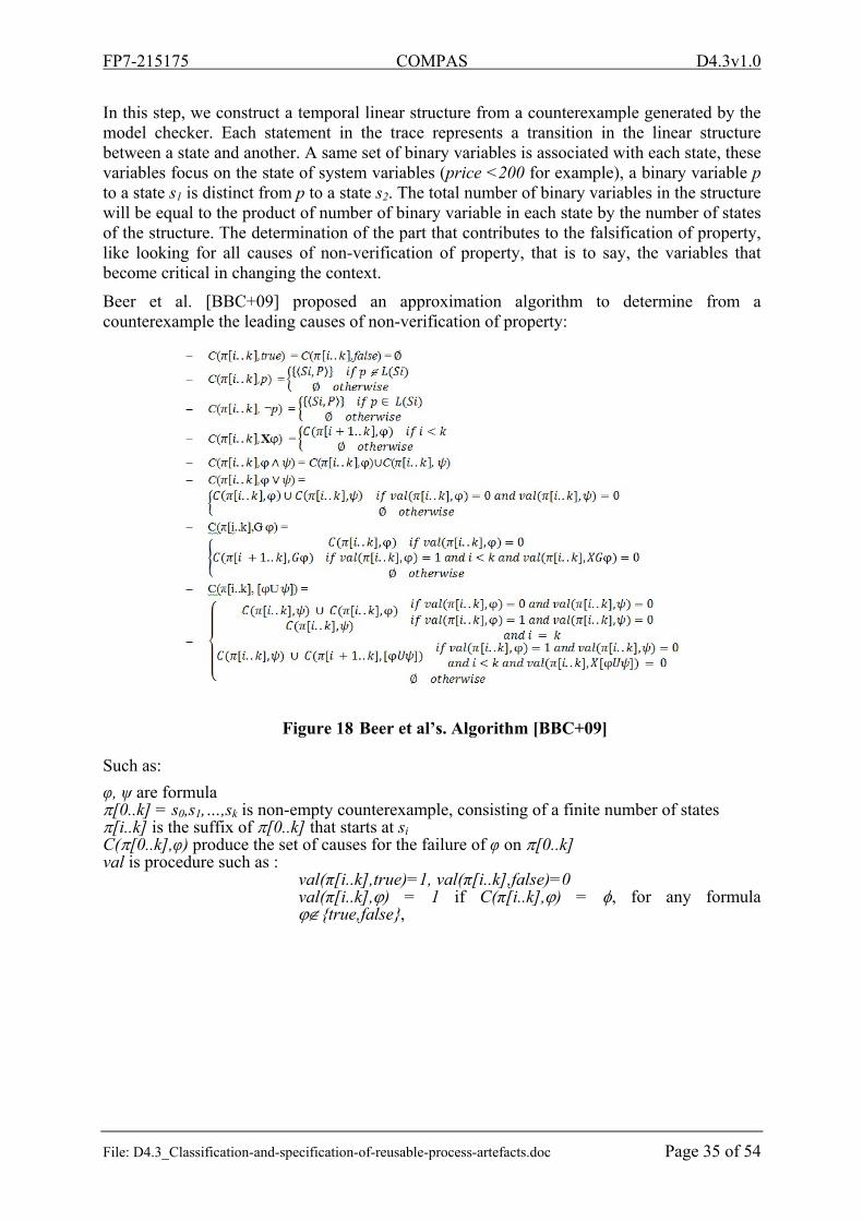
The formal definition of the concept of causality used in this work builds on the work of Beer et al. [BBC+09]. The authors proposed an algorithm to determine from a counterexample such major causes of a malfunction of a system. Halpern et al. [HP01] have proposed a new definition of causality using structural equations. Eiter et al. [EL01] investigated the complexity of determining all causes in a binary causal model and Chockler [CHK08] defined the notion of responsibility for verification of a specification. Our work rests on the following two definitions:
Definition of Critical variable [3, 7]: Let M be a model, the current context, and η a Boolean formula. Let (M, ) |= η, and X a Boolean variable in M that has the value x in the context , and the other possible value (0 or 1). We say that (X = x) is critical for η in (M, ) if (M, ) |= (X ←¬x)¬η. That is, changing the value of X to ¬x falsifies η in (M, ).
Definition of Cause [3, 19, 12]: We say that X = x is a cause of η in (M, ) if the following conditions hold:
AC1. (M, ) |= (X = x) η. AC2. There exists a subset of V with X and some setting of the variables in such that setting the variables in to the values makes (X = x) critical for the satisfaction of η.
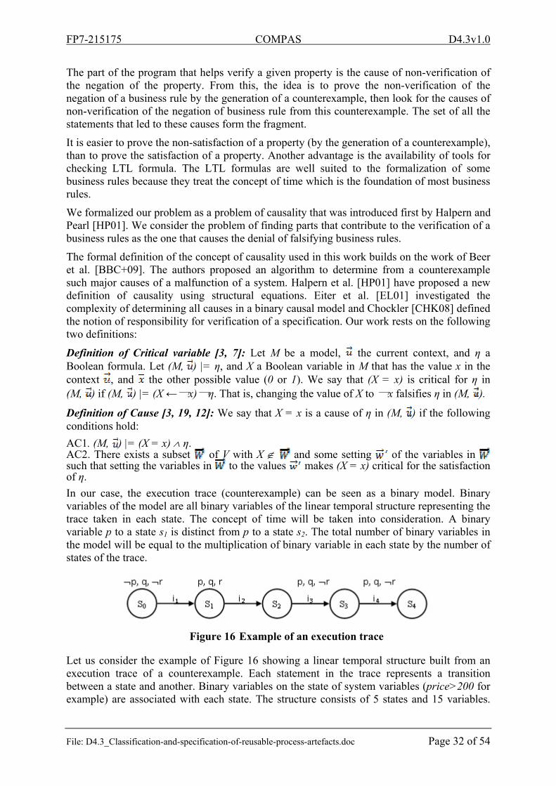
In our case, the execution trace (counterexample) can be seen as a binary model. Binary variables of the model are all binary variables of the linear temporal structure representing the trace taken in each state. The concept of time will be taken into consideration. A binary variable p to a state s1 is distinct from p to a state s2. The total number of binary variables in the model will be equal to the multiplication of binary variable in each state by the number of states of the trace.
Figure 16 Example of an execution trace
Let us consider the example of Figure 16 showing a linear temporal structure built from an execution trace of a counterexample. Each statement in the trace represents a transition between a state and another. Binary variables on the state of system variables (price>200 for example) are associated with each state. The structure consists of 5 states and 15 variables.
FP7-215175 COMPAS D4.3v1.0
File: D4.3_Classification-and-specification-of-reusable-process-artefacts.doc Page 33 of 54
Let a formula = G(r), r is critical for , because if we reverse that in s1, becomes valid, so (r,s1) is a cause of non verification of . Let now the formula = G(q r), r in s1 is not critical for but if we inverse q in s4 it will become critical, so we can say that (r, s1) is a cause for . This illustrates the difference between a critical variable and a cause.
Based on the foregoing definition of cause, the determination of all possible causes of malfunction in a system modelled by a binary model [HP01] is NP-complete [EL01], the number of possible cases is exponential. One might also note that in real systems the number of states may be infinite, which complicates the problem.
4.3.2. Approach
Let us consider an example of a process of online purchase in the form of a complex choreography of web services. For example, if the supplier wants to secure the payment process without affecting other functionalities, it will be more interesting to determine which party carries out this functionality to work throughout the process, which can be a very difficult task when the process is complex. Hence the need to seek the party that contributes to the functionality, which can be seen as a fragmentation process by a property of type "F(money_received)" becomes interesting. The goal of our work is the fragmentation of the compositions of web services from a business rule expressible in LTL. In other words, given a business rule that can be formalized in LTL, we want to determine the part of a composition of web services that contributes to the verification of the business rule. The composition of web services will be expressed in BPEL. One major advantage of the fragmentation of the compositions of web services is that it allows a grouping according to the feature on a web service composition. We can also cite other advantages such as simplicity and reuse both in the update or the query.
Figure 17 General principle of fragmentation
The general principle of our approach is illustrated in Figure 17. It is much easier to prove the non-verification of the negation of a property than to prove the verification of this property. The proof of the non-verification is based on the generation of a counterexample. The intuition is that a party that contributes to the non-verification of a property that contributes to the verification of the negation of that property.
FP7-215175 COMPAS D4.3v1.0
File: D4.3_Classification-and-specification-of-reusable-process-artefacts.doc Page 34 of 54
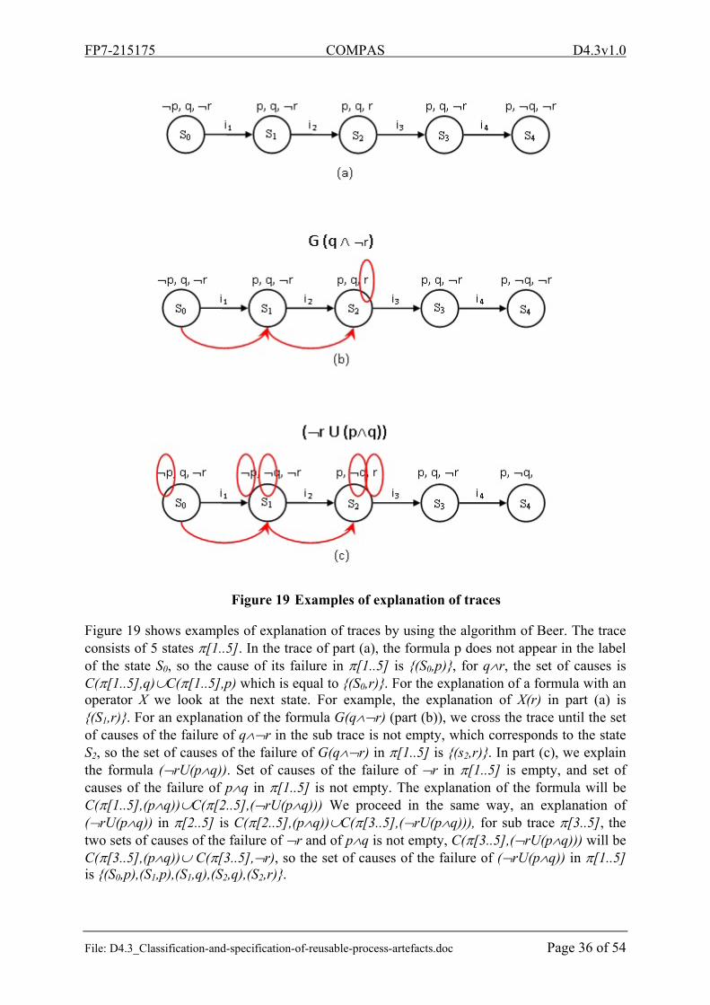
In our approach, the fragmentation of a web service composition is mainly done through three steps: verification, explanation of the trace and the construction of the fragment. The verification is to show that the negation of the business rule is not checked, this is done by generating a counterexample using the SPIN model checker. The explanation of the trace is to seek the causes of the falsification of the negation of the business rule. The construction of the fragment is to select the statements that contribute to the achievement of the causes identified by the previous step. We will detail each step in the following.
4.3.3. Verification
The first step of fragmentation is to produce a counterexample to show that the negation of the business rule is not checked. To generate a counterexample we use verification techniques of web services. We use SPIN as a model checker because it is more oriented to concurrent systems [KPR04]. SPIN takes as input an LTL formula and a model of the system to check expressed in PROMELA. There are two methods for working with SPIN: direct and indirect. Several options for checks or simulation can be used.
We consider web service compositions expressed in BPEL, but the entry of SPIN must be specified in PROMELA which is a language for specifying concurrent systems, so we must translate specification make the transition from BPEL to PROMELA in order to use SPIN. We use WSAT (Web Service Analysis Tool) [BFS04] proposed by Fu et al. [FBS04] who worked on the analysis of interactions in a BPEL composition of Web services using SPIN, they have developed WSAT for the conversion from a BPEL to PROMELA. The switchover occurs by abstraction of a web service composition in the form of a set of Peers, and a pattern
of conversation, each peer is represented by a guarded automata2. The authors propose a set of rules to move from the proposed abstraction to a PROMELA code.
WSAT is a formal specification, verification, and analysis tool for web service compositions. The tool supports multiple specification approaches of composite web services, including BPEL4WS and WSDL specifications, Guarded Automata (GA) based (top-down) conversation protocols, and (bottom-up) GA service compositions. WSAT translates web service input into PROMELA, and allows model checking of web service designs without loss of (bounded and XPath based) XML data semantics. In addition, WSAT provides several analyses techniques that can reduce complexities in the formal verification of asynchronously communication web services.
4.3.4. Explanation
After generating the counterexample, we must explain and seek the causes of non-verification rule. We explain the causes of the non-verification of the negation of the business rule in order to explain the audit of the business rule, that is to say that fragmentation will be on the negation of the formula from which we generated the counterexample. For example, if the fragmentation is based on the formula G (p), the explanation will be on formula F(p). The explanation of the track is the most important step in the process, the quality of fragmentation depends on this step.
2 Guarded automaton is a structure A = (M, T, s, F, ), where M is the set of message classes, T a finite set of states, s T the
initial state, F T a set of final states, and the transition relation. Each transition is of the form = (s, (c, g), t). Here, s, t T are the source and the destination states of the transition , c M is a message type and g is the guard of the transition. A guard consists of a guard condition and a set of assignments.
FP7-215175 COMPAS D4.3v1.0
File: D4.3_Classification-and-specification-of-reusable-process-artefacts.doc Page 35 of 54
In this step, we construct a temporal linear structure from a counterexample generated by the model checker. Each statement in the trace represents a transition in the linear structure between a state and another. A same set of binary variables is associated with each state, these variables focus on the state of system variables (price <200 for example), a binary variable p to a state s1 is distinct from p to a state s2. The total number of binary variables in the structure will be equal to the product of number of binary variable in each state by the number of states of the structure. The determination of the part that contributes to the falsification of property, like looking for all causes of non-verification of property, that is to say, the variables that become critical in changing the context.
Beer et al. [BBC+09] proposed an approximation algorithm to determine from a counterexample the leading causes of non-verification of property:
Figure 18 Beer et al’s. Algorithm [BBC+09]
Such as:
φ, ψ are formula [0..k] = s0,s1,…,sk is non-empty counterexample, consisting of a finite number of states [i..k] is the suffix of [0..k] that starts at si C([0..k],φ) produce the set of causes for the failure of φ on [0..k] val is procedure such as :
val(π[i..k],true)=1, val(π[i..k],false)=0 val(π[i..k],) = 1 if C(π[i..k],) = , for any formula {true,false},
FP7-215175 COMPAS D4.3v1.0
File: D4.3_Classification-and-specification-of-reusable-process-artefacts.doc Page 36 of 54
Figure 19 Examples of explanation of traces
Figure 19 shows examples of explanation of traces by using the algorithm of Beer. The trace consists of 5 states [1..5]. In the trace of part (a), the formula p does not appear in the label of the state S0, so the cause of its failure in [1..5] is {(S0,p)}, for qr, the set of causes is C([1..5],q)C([1..5],p) which is equal to {(S0,r)}. For the explanation of a formula with an operator X we look at the next state. For example, the explanation of X(r) in part (a) is {(S1,r)}. For an explanation of the formula G(qr) (part (b)), we cross the trace until the set of causes of the failure of qr in the sub trace is not empty, which corresponds to the state S2, so the set of causes of the failure of G(qr) in [1..5] is {(s2,r)}. In part (c), we explain the formula (rU(pq)). Set of causes of the failure of r in [1..5] is empty, and set of causes of the failure of pq in [1..5] is not empty. The explanation of the formula will be C([1..5],(pq))C([2..5],(rU(pq))) We proceed in the same way, an explanation of (rU(pq)) in [2..5] is C([2..5],(pq))C([3..5],(rU(pq))), for sub trace [3..5], the two sets of causes of the failure of r and of pq is not empty, C([3..5],(rU(pq))) will be C([3..5],(pq)) C([3..5],r), so the set of causes of the failure of (rU(pq)) in [1..5] is {(S0,p),(S1,p),(S1,q),(S2,q),(S2,r)}.
FP7-215175 COMPAS D4.3v1.0
File: D4.3_Classification-and-specification-of-reusable-process-artefacts.doc Page 37 of 54
In the case of compound formulas, the explanation is done by composition of basic explanation operators. It starts first by putting the formula in a negation normal form (we distributed the negation operator pushed it to the right most possible, until it is applied to atomic propositions) then we apply the explanation rules of the basic operators, and by composition found the explanation of the formula. For example, let us consider the formula (G(p)(rUq)). We start by pushing the negation, we obtain the following form F(p)G(r)(q(X(q)Ur)) Then we compose the explanation of basic operators and we obtain C([i..k],F(p)G(r)(q(X(q)Ur))) which is equal to C([i..k],F(p))C([i..k],G(r)) C([i..k],q(X(q)Ur)).
Given a counterexample [0..k] of a formula F(p), such as p is an atomic formula. The explanation of the error will be composed by the entire track (last rule of the algorithm, such as F(p)trueUp), Thus the fragmentation of the operator G selects all states of the trace, This may not be effective in some cases. The problem arises in the definition of fragment itself. The question that arises is how to measure the quality of fragmentation? We will see later the definition of a fragment from two different points of view.
The objective of Beer et al. was the determination of the leading causes of non-verification of a property. They explain the failure of a type formula G (p) by the first state responsible for the failure of the property p, in terms of fragmentation, formula is F(p), so the fragment will be the first part which contributes to the verification of p. This result may be acceptable, but it will be interesting to capture the most possible states which contribute to p. The model checker SPIN allows a full verification on the system specification, that is to say, we can force it to not stop at the first failure in verification of a formula of type G(p). This allows us to find the most of the states contributing to non-verification of p so that fragmentation will be more accurate.
We will detail later the process of construction of fragments. According to the two previous definitions, we will propose two types of fragmentation, and we will compare the two.
4.3.5. Construction of fragments
The last phase of the process of fragmentation is the construction phase of the fragment. The objective of this step is to find statements that contribute to changes impacting the state of variables involved in the explanation of the trace (previous step), we use for this slicing techniques.
After explaining in terms of variables the causes of non-verification of the negation of business rule, we should consider statements to build the fragment. To do so we use techniques of slicing concurrent programs, Nanda et al. [NR00].
A fragment will include a portion of the fragmented process statements. As temporal logic is based on the concept of time, if we eliminate a set of statements, we will eliminate a set of states, that is to say we will adjust the chronology. This may affect the validity of the property on a slicing particularly in the case of a formula with a "Next" operator. To solve this problem we will replace each statement eliminated by a statement that does nothing (skip). We associate it a set of variables, we will the role of these variables. As illustrated in Figure 20, the fragment has the same structure as the fragmented process.
FP7-215175 COMPAS D4.3v1.0
File: D4.3_Classification-and-specification-of-reusable-process-artefacts.doc Page 38 of 54
Figure 20 Format of a fragment
Any statement involved in the change of state variables is considered as being part of the fragment. The idea is to seek any statements with which the selected variables in explanation step depend. We will perform a slicing for all causes selected by the previous step, and then we construct the fragment by the union of all found program slice. A slicing requires two inputs: a variable and a point in the program. In our work, a cause will be considered as an input slicing knowing that:
The slicing variable is the boolean variable of cause. The slicing criterion is the transition that precedes the state of the cause.
Note: Linear structure transitions represent program statements.
Figure 21 reuses the example of Figure 19 (c). It summarizes the construction phase of the fragment. We perform a slicing for each case determined by explanation step, and then we will make the union of all the resulting slice programs to build the fragment. In the slicing of a variable x we replace each statement eliminated by skipx which can be any statement that does not change the value of x. We define the intersection of two program slices by another program slice constructed by the intersection line by line of the two program slices such as skipxskipy=skipx,y and skipxstatement=statement.
FP7-215175 COMPAS D4.3v1.0
File: D4.3_Classification-and-specification-of-reusable-process-artefacts.doc Page 39 of 54
Figure 21 Construction of a fragment
4.3.6. Refinement of a fragment
Let us consider an example of a process of online purchase. We assume that the bank would not accept a negative account, so for a purchase transaction to be validated, the client must have an account greater than or equal to the product price. We can say that throughout the buying process the customer's account is greater than or equal to zero, therefore the property (account >= 0) is checked every time, therefore p = G(account >= 0) is valid. Now, looking for the fragmentation with p. It must exist in the process a test "if(account >= price) account = account – price ;". It is clear that if we remove the test "if(account >= price)", the property could be violated. This test is necessary for the preservation of property (account >= 0). Returning to our fragmentation, how to define the fragment? Is it just that the test constitute a fragment since it is the only statement necessary for the preservation of property? From another point of view, we can say that the other statements also contribute to verification of the property because it does not violate the property. The problem is that a formula of "G" is checked through the whole process, so is it possible to isolate in the case of the operator "G" a part of the process over to another part? To try to answer this question, we propose an extension of our approach based on another definition of a fragment.
FP7-215175 COMPAS D4.3v1.0
File: D4.3_Classification-and-specification-of-reusable-process-artefacts.doc Page 40 of 54
Because of these characteristics, the treatment of the "G" operator is special. The question is philosophical: how to define a fragment based on rules verified in all statements of a process?
We define a fragment as the necessary part which contributes to the verification and preservation of property that is the part such that if one removes the property it will not be verified.
Figure 22 illustrates this definition. We see that in the first case the property remains true despite the elimination of a statement but it becomes false in the second case, therefore it is clear that there are differences between the statements of a fragment. To study this we proposed a refinement of the fragment to try to produce more relevant fragments. The question is then what are the criteria of the quality of a fragment?
Figure 22 Difference between the statements of a fragment
The refinement of a fragment is based on the idea of the apriori algorithm [AS94]. The general principle is illustrated in Figure 23. We construct a lattice from combinations of statements of fragment (without using the skip), the objective is to seek the smallest combinations of statements needed by browsing through the lattice level, if a necessary node is found then all combinations including the node will be eliminated. The idea is to minimize the size of the fragment.
FP7-215175 COMPAS D4.3v1.0
File: D4.3_Classification-and-specification-of-reusable-process-artefacts.doc Page 41 of 54
Figure 23 Search required statements by the apriori algorithm
4.4. Discussion
In our work, traces are finite. In some systems the use of infinite traces is necessary. For example, a fragmentation regarding a formula that includes a "G" operator in system without final state requires infinite traces. The extension of our approach will be necessary for this type of system.
In explanation step we used the algorithm of Beer et al. This algorithm provides an approximate set of causes and does not provide additional information on the causes, all provided causes are not necessarily minimum (for example in Figure 15c the binary variable p in state s0 is critical, the inversion of this variable is sufficient for the formula to become true in the trace). Searching all possible causes is NP-complete. It is then necessary to improve this step because the quality of fragmentation depends directly on the quality of the explanation.
In the refinement of the fragment, our goal is to focus on the difference between two types of statements in a fragment, statements necessary for the preservation of property and statements that are not required. The problem of finding the combination of statements that we presented is NP-complete. It is obvious that if the fragment is large and pruning is low, the algorithm will not perform. Our main objective is to raise the issue. We want to see the benefits brought by a fragment if we change the program. It will be interesting to investigate this issue.
4.5. Conclusion and future work
In this work, we have shown how model checking and slicing techniques can be combined to perform fragmentation of a BPEL web service composition. We start by proving that the
FP7-215175 COMPAS D4.3v1.0
File: D4.3_Classification-and-specification-of-reusable-process-artefacts.doc Page 42 of 54
negation of a business rule is not checked, by generating a counterexample using a model checker. We modelled a counterexample as a linear time structure, and then we search the states of the structure responsible for the failure. From these statements we determine the set of statements that form the fragment. The advantage of our approach is the possibility of fragmenting according to temporal properties, the fragment is oriented business but it remains to validate the approach by testing to discover the performance of the method and feasibility in terms of complexity.
One lack of our approach is the ad-hoc combination of disparate technics to tackle the problem of fragmentation. A uniform theory is still needed and temporal theorem proving seems to be a good candidate to unify it.
In our work, we fragmented business processes according to business rules expressible in LTL. It will be interesting to extend the fragmentation rules expressible in CTL. It is also interesting to extend our model to work with infinite traces which cannot be avoided in some system for a fragmentation regarding the “G” operator. One of our future work is to implement the approach to test and study the feasibility and performance of the model on real applications. We intend to design and implement a framework which does not depend on the format of the definition of web service composition, whether a BPEL code or other things. We also plan to improve the refinement of a fragment to explore this issue and investigate whether the refinement of a fragment is necessary.
5. Reference documents
5.1. Internal documents
[DoW] “Description of Work for COMPAS”, 2008-02-01.
[D2.5] “Specification of an Extension to BPEL for Adaptability – Final Version”, M30.
[D4.1] “State-of-the-art report on the existing approaches to improving reusability of processes and service compositions”, 2008-12-31.
[D4.2] “BPEL extensions for compliant services”, 2009-12-31.
[D4.4] “Supporting infrastructure – process engine, process artefact repository, process generation tool”, 2009-12-31, M35.
[D5.3] “Final goal-oriented data model”, 2009-07-31.
[D5.4] “Reasoning mechanisms to support the identification and the analysis of problems associated with user requests”, 2009-12-31.
[D6.1] “Use Cases Definition, Metrics, and Validation Scenarios for Case Studies”. Ver. 1.0 of 2008-07-31.
File: D4.3_Classification-and-specification-of-reusable-process-artefacts.doc Page 43 of 54
5.2. External documents
[AAD+07] A. Agrawal, M. Amend, M. Das, M. Ford, C. Keller, M. Kloppmann, D. König, F. Leymann, R. Müller, G. Pfau, K. Plösser, R. Rangaswamy, A. Rickayzen, M. Rowley, P. Schmidt, I. Trickovic, A. Yiu and M. Zeller: WS-BPEL Extension for People (BPEL4People), Version 1.0, White Paper, 2007, http://download.boulder.ibm.com/ibmdl/pub/software/dw/specs/ws-bpel4people/BPEL4People_v1.pdf
[Aal99] W.M.P. van der Aalst: Generic Workflow Models: How to Handle Dynamic Change and Capture Management Information? In: Proceedings of the Fourth IECIS International Conference on Cooperative Information Systems (COOPIS'99). IEEE Computer Society, 1999.
[AFK05] J. Arias-Fisteus, L.S. Fernández, and C.D. Kloos: Applying model checking to BPEL4WS business collaborations. In Proceedings of the 2005 ACM Symposium on Applied Computing (SAC), ACM, pages 826-830, 2005.
[AH05] W.M.P. van der Aalst and A.H.M. ter Hofstede: YAWL: Yet Another Workflow Language. Information Systems, 30(4):245-275, 2005.
[APQC09] American Productivity and Quality Center: Process Classification Framework (PCF), 2009, http://www.apqc.org/knowledge-base/documents/apqc-process-classification-framework-pcf-cross-industry-pdf-version-510
[AS94] R. Agrawal and R. Srikant: Fast algorithms for mining association rules in large databases. In Proceedings of the 20th International Conference on Very Large Data Bases, pages 487-499. Morgan Kaufmann Publishers Inc., 1994.
[BBC+09] I. Beer, S. Ben-David, H. Chockler, A. Orni, and R. Trefler: Explaining Counterexamples Using Causality. In Computer Aided Verification, pages 94-108. Springer, 2009.
[BEK+05] C. Beeri, A. Eyal, S. Kamenkovich, and T. Milo: Querying business processes with BP-QL. In VLDB, pages 1255-1258, 2005.
[BFS04] T. Bultan, X.Fu, and J. Su: WSAT: Web Service Analysis Tool. 2004, http://www.cs.ucsb.edu/~su/WSAT/.
[BGP+05] M. Bruno, G. Canfora,M. D. Penta and R.Scognamiglio: An Approach to support Web Service Classification and Annotation in the Proceedings of the IEEE International Conference on e-Technology, e-Commerce and e-Service (EEE'05) on e-Technology, e-Commerce and e-Service, 2005.
[BNR03] T. Ball, M. Naik, and S.K. Rajamani: From symptom to cause: Localizing errors in counterexample traces. ACM SIGPLAN Notices, 38(1):105, 2003.
[BRG00] The Business Rules Group: Defining Business Rules: What Are They Really ? July 2000, http://www.businessrulesgroup.org/first_paper/br01c0.htm.
[CES09] E.M. Clarke, E.A. Emerson, and J. Sifakis: Model checking: algorithmic verification and debugging. Communications of the ACM, 52(11):74-84, 2009.
[CGP99] E. Clarke , O. Grumberg, and D. Peled: Model Checking. MIT Press, 1999.
[CHK08] H. Chockler, J.Y. Halpern, and O. Kupferman: What causes a system to satisfy a specification? ACM Transactions on Computational Logic (TOCL), 9(3):20, 2008.
FP7-215175 COMPAS D4.3v1.0
File: D4.3_Classification-and-specification-of-reusable-process-artefacts.doc Page 44 of 54
[CMR+07] R. Chinnici, J-J. Moreau, A. Ryman and S. Weerawarana: Web Services Description Language (WSDL) Version 2.0 Part 1: Core Language. W3C Recommendation, June 2007.
[CPK03] P. Chountas, I. Petrounias and V. Kodogiannis: Temporal Modelling in Flexible Workflows, ISCIS, 2003.
[DFK06] C. Dixon, M. Fisher, and B. Konev: Is There a Future for Deductive Temporal Verification? In Temporal Representation and Reasoning, 2006. TIME 2006. Thirteenth International Symposium on, pages 11-18, 2006.
[DKL9] O. Danylevych, D. Karastoyanova, and F. Leymann: Optimal stratification of transactions. In 2009 Fourth International Conference on Internet and Web Applications and Services, pages 493-498. IEEE, 2009.
[DLS04] A.A. Diaz, O. Lorenzo, and L.E. Solis: A taxonomy of business processes, Instituto de Empresa, Area of Economic Environment, 2004.
[EL01] T. Eiter and T. Lukasiewicz: Complexity results for structure-based causality. In IJCAI, pages 35-42, 2001.
[Eme91] A. Emerso: Temporal and Modal Logic. Handbook of Theoretical Computer Science, Volume B: Formal Models and Sematics (B): 995-1072, MIT Press, 1991.
[ETV+10] A. Elgammal, O. Turetken, W. J. van den Heuvel, and M. Papazoglou: On the formal specification of business contracts and regulatory compliance. In FLACOS 2010 Fourth Workshop on Formal Languages and Analysis of Contract-Oriented Software.
[FB92] W.B.Frakes and R.Baeza-Yates: Information retrieval: data structures and algorithms. Prentices-Hall, Englewood Cliffs, NJ, 1992.
[FBS04] X. Fu, T. Bultan, and J. Su: Analysis of interacting BPEL web services. In Proceedings of the 13th international conference on World Wide Web, pages 621-630. ACM, 2004.
[Fis91] M. Fisher: A resolution method for temporal logic. In Proceedings of the Twelfth International Joint Conference on Artificial Intelligence (IJCAI), pages 99-104. Citeseer, 1991.
[Fri10] J. P. Friedman: Dictionary of Business Terms, 2010. . http://nisethkhmer.files.wordpress.com/2010/04/banking-dictionary1.pdf
[GP08] D. M. Gabbay and A. Pnueli: A sound and complete deductive system for ctl* verification. Logic Journal of the IGPL, 16(6):499-536, 2008.
[HKR+04] U. Hustadt, B. Konev, A. Riazanov, and A. Voronkov: Temp: A temporal monodic prover. In In Proc. IJCAR-04, LNAI, pages 326-330. Springer, 2004.
[Hol04] G.J. Holzmann: The SPIN model checker: Primer and reference manual. Addison Wesley Publishing Company, 2004.
[Hol97] G. Holzmann: The Model Checker SPIN, IEEE Transactions on Software Engineering, Vol. 23, No. 5, May 1997
[HP01] J. Y. Halpern and J. Pearl: Causes and explanations: A structural-model approach - Part I: Causes. In UAI, pages 194-202, 2001.
FP7-215175 COMPAS D4.3v1.0
File: D4.3_Classification-and-specification-of-reusable-process-artefacts.doc Page 45 of 54
[HPH10] F. Hantry, M. Papazoglou, and M. S. Hacid: Formal model for business-aware transaction management. In FLACOS 2010 Fourth Workshop on Formal Languages and Analysis of Contract-Oriented Software.
[IBM03] Business Process Execution Language for Web Services (BPEL), Version 1.1, 2003. http://www.ibm.com/developerworks/library/ws-bpel
[Kha08] R. Khalaf: Supporting business process fragmentation while maintaining operational semantics: a BPEL perspective. Doctoral thesis, University of Stuttgart, Faculty of Computer Science, Electrical Engineering, and Information Technology, Germany, March 2008.
[Kin04] E. Kindler: On the Semantics of EPCs: A Framework for Resolving the Vicious Circle. Proceedings of the 2nd International Conference on Business Process, pages 82–97, 2004.
[KPR04] R. Kazhamiakin, M. Pistore, and M. Roveri: Formal verification of requirements using spin: A case study on web services. In SEFM, pages 406-415, 2004.
[LQS+07] A. Lomuscio, H. Qu, M. Sergot, and M. Solanki: Verifying temporal and epistemic properties of web service compositions. Service-Oriented Computing-ICSOC 2007, pages 456-461.
[MDK+09] M. Mancioppi, O. Danylevych, D. Karastoyanova, F. Leymann, M. Papazoglou: The Kaleidoscope of Fragmentation of Service Compositions. Network of Excellence S-Cube, 2009.
[MP91] Z. Manna and A. Pnueli: Completing the temporal picture. Theor. Comput. Sci., 83(1):97-130, 1991.
[MP95] Z. Manna and A. Pnueli: Temporal verification of reactive systems: safety. Springer-Verlag New York, Inc., New York, NY, USA, 1995.
[MZ09] K. L. McMillan and L. D. Zuck: Abstract counterexamples for non-disjunctive abstractions. In RP, pages 176-188, 2009.
[NC04] D. Neiger and L. Churilov: Goal-oriented business process modeling with EPCs and value focused thinking. Business Process Management, pages 98-115, 2004.
[NR00] M.G. Nanda and S. Ramesh: Slicing concurrent programs. In Proceedings of the 2000 ACM SIGSOFT international symposium on Software testing and analysis, page 190. ACM, 2000.
[NWG01] Network Working Group: Internet X.509 Public Key Infrastructure Time-Stamp Protocol (TSP), RFC 3161, 2001. http://tools.ietf.org/html/rfc3161
[OASIS05] OASIS: UDDI Version 3 Specification. OASIS Standard, 2005, http://www.oasis-open.org/committees/uddi-spec/doc/tcspecs.htm.
[OASIS07] A. Alves, A. Arkin, S. Askary, C. Barreto, B. Bloch, F. Curbera, M. Ford, Y.Goland, A. Guízar, N. Kartha, C.K. Liu, R. Khalaf, D. König, M. Marin, V. Mehta, S. Thatte, D. van der Rijn, P. Yendluri, and A. Yiu: Web Services Business Process Execution Language Version 2.0. OASIS Comitee Specification, April 2007, http://docs.oasis-open.org/wsbpel/2.0/wsbpel-v2.0.pdf
FP7-215175 COMPAS D4.3v1.0
File: D4.3_Classification-and-specification-of-reusable-process-artefacts.doc Page 46 of 54
[OMG08] Object Management Group: Business Process Modeling Notation, OMG Available Specification, Version 1.1, January 2008, http://www.omg.org/spec/BPMN/1.1/PDF
[OTS+04] N. Oldham, C. Thomas, A. Sheth, K. Verma: METEOR-S. Proceedings of the 1st Int. Workshop on Semantic Web Services and Web Process Composition (SWSWPC’04), 2004.
[Pap07] M. Papazoglou: Web Services: Principles and Technology. Pearson - Prentice Hall, 782 pages, 2007.
[SB98] G. Salton, C. Buckley: Term Weighting Approaches in Automatic Text Retrieval, Information Processing and Management, Vol. 24, No.5, P513, (1998).
[SKL+09] D. Schumm, D. Karastoyanova, F. Leymann, J. Nitzsche: On Visualizing and Modelling BPEL with BPMN. Grid and Pervasive Computing Workshops: 4th International Workshop on Workflow Management (ICWM), IEEE Press, 2009.
[SKL+10] D. Schumm, D. Karastoyanova, F. Leymann, S. Strauch: Fragmento: Advanced Process Fragment Library. Proceedings of the 19th Int. Conference on Information Systems Development (ISD 2010), Springer, 2010 (to appear).
[SLM+10] D. Schumm, F. Leymann, Z. Ma, T. Scheibler, S. Strauch: Integrating Compliance into Business Processes: Process Fragments as Reusable Compliance Controls. Proceedings of the Multikonferenz Wirtschaftsinformatik (MKWI’10), 2010.
[SLS10] D. Schumm, F. Leymann, A. Streule: Process Views to Support Compliance Management in Business Processes. Proceedings of the 11th Int. Conference on Electronic Commerce and Web Technologies (EC-Web 2010), Springer, 2010 (to appear).
[SMS08] P. A. Smart, H. Madden and R. S. Maull: Understanding Business process management: Implications for theory and practice. British Journal of Management, 2008. http://eric.exeter.ac.uk/exeter/bitstream/10036/48234/1/0708.pdf .
[Tip95] F. Tip: A survey of program slicing techniques. Journal of programming languages, 3(3):121-189, 1995.
[VAP98] V.N. Vapnik: statistical learning theory. John Wiley, Sept. 1998.
[VCH10] R. Ivanovic, M. Carro, M. Hermenegildo: Sharing-Based Independence-Driven ment Identification for Service Orchestration, Network of Excellence S-Cube, 2010.
[VVL07] J. Vanhatalo, H. Volzer, and F. Leymann: Faster and more focused control-flow analysis for business process models through sese decomposition. Service-Oriented Computing-ICSOC 2007, pages 43-55, 2007.
[ZHL10] S. Zaplata, K. Hamann, W. Lamersdorf: Executing Parallel Tasks in Distributed Mobile Processes. Network of Excellence S-Cube, 2010.
[ZKM+09] S. Zaplata, K. Kottke, M. Meiners, and W. Lamersdorf: Towards Runtime Migration of WS-BPEL Processes. WESOA 2009.
FP7-215175 COMPAS D4.3v1.0
File: D4.3_Classification-and-specification-of-reusable-process-artefacts.doc Page 47 of 54
[ZD08] J. Zhang and P. Dan: Web Service Classification. http://www.ics.uci.edu/~dramanan/teaching/ics273a_winter08/projects/danpan.pdf , 2008.
[ZYQ06] X. Zhao, H. Yang, and Z. Qiu: Towards the formal model and verification of web service choreography description language. Proc. of WS-FM 2006, pages 273-287, 2006.
FP7-215175 COMPAS D4.3v1.0
File: D4.3_Classification-and-specification-of-reusable-process-artefacts.doc Page 48 of 54
Appendices
A. Appendix A: Process fragment for user login In this part of the appendix we show the complete code of a process fragment which has been designed and implemented for the WatchMe scenario. The process fragment realizes the compliance requirement for user login. Section A.1 shows the graphical display of the process fragment in the Eclipse BPEL Designer environment. This rendering is not a standardized rendering. BPMN is the de-facto graphical rendering of BPEL, which we used in Section 2. Section A.2 lists the corresponding code.
A.1. Rendering of the process fragment in the Eclipse BPEL designer
Figure 24 Process fragment for user login in Eclipse BPEL Designer
FP7-215175 COMPAS D4.3v1.0
File: D4.3_Classification-and-specification-of-reusable-process-artefacts.doc Page 49 of 54
A.2. XML serialization of the process fragment <?xml version="1.0" encoding="UTF-8"?>
<!-- Process Fragment Access to WatchMe Service is protected -->