118
® D430691XA vers. 7.0 Operating manual

®
D430691XAvers. 7.0
Operating manual

(c) 2006 SILCA S.p.A. - Vittorio Veneto
This manual has been drawn up by SILCA S.p.A.All rights reserved. No part of this publication may be reproduced or used in any form or by any means (photocopying, microfilm or other) without the permission of SILCA S.p.A.
Edition: july 2012
Printed in Vittorio Venetoby SILCA S.p.A.via Podgora, 20 (Z.I.)31029 VITTORIO VENETO (TV) - Italy
IMPORTANT NOTE: in compliance with current regulations relating to industrial property, we hereby state that the trade-marks or trade names mentioned in our documentation are the exclusive property of authorized manufacturers of locks and users. Said trade-marks or trade names are nominated only for the purposes of information so that any lock for which our keys are made can be rapidly identified.

INDEXREFERENCE GUIDE ................................................................................................................. 1
GENERAL ................................................................................................................................... 2
1 MACHINE DESCRIPTION .....................................................................................................4
1.1 MAIN CHARACTERISTICS ........................................................................................................... 4
1.2 SAFETY ................................................................................................................................... 5
1.3 MAIN WORKING PARTS ............................................................................................................. 6
1.4 TECHNICAL DATA ..................................................................................................................... 7
1.5 ACCESSORIES PROVIDED ......................................................................................................... 8
2 TRANSPORT .........................................................................................................................9
2.1 PACKING .................................................................................................................................. 9
2.2 UNPACKING ............................................................................................................................. 9
2.3 MACHINE HANDLING ............................................................................................................... 10
3 MACHINE INSTALLATION AND PREPARATION ..............................................................11
3.1 CHECKING FOR DAMAGE ........................................................................................................ 11
3.2 ENVIRONMENTAL CONDITIONS ................................................................................................ 11
3.3 POSITIONING ......................................................................................................................... 11
3.4 DESCRIPTION OF WORK STATION ............................................................................................ 12
3.5 GRAPHICS ............................................................................................................................. 12
3.6 SEPARATE PARTS .................................................................................................................. 12
4 REGULATION ANd USE OF THe MACHINE ......................................................................13
4.1 KEYPAD AND FUNCTION KEYS ................................................................................................. 13
4.2 USE OF THE CLAMP ............................................................................................................... 14
4.3 LOCKING THE KEYS ................................................................................................................ 15
4.4 FITTING THE CLAMP TO THE MACHINE ..................................................................................... 18
4.5 CUTTER ................................................................................................................................ 19
4.6 CHANGING THE CUTTER AND/OR THE TRACER POINT ............................................................... 19
5 OPERATING GUIDE ............................................................................................................20
5.1 SYMBOLS AND TERMINOLOGY ................................................................................................. 20
5.2 INITIAL OPERATIONS ............................................................................................................... 21
5.3 DECODING AND COPY - 0 ....................................................................................................... 23
5.4 INSERT THE CUTS - 1 ............................................................................................................ 275.4.0.1 CHANGE KEY MATERIAL FUNCTION - F=BRASS/STEEL ..................................................28
5.5 LIST OF CODES - 2 ................................................................................................................ 30
5.6 USE OF THE MACHINE WITH A PERSONAL COMPUTER .............................................................. 34
5.6.1 QUEUE FROM PC - 3 ........................................................................................................... 345.6.2 KEY DECODING BY PC ........................................................................................................ 35
5.7 CALIBRATIONS ....................................................................................................................... 36
5.7.1 AUTOMATIC CALIBRATION OF CLAMP ..................................................................................... 365.7.2 CUTTER CALIBRATION .......................................................................................................... 415.7.3 DECODER CALIBRATION ....................................................................................................... 44
5.7.3.1 MANUAL GAUGING OF DECODER (U111DC) ......................................................45
5.7.4 ADAPTORS CALIBRATION ...................................................................................................... 475.7.5 USER ADJUSTMENTS ........................................................................................................... 49
5.8 MAINTENANCE - 4 .................................................................................................................. 50
5.8.1 CUTTERS ............................................................................................................................ 505.8.2 TEST ................................................................................................................................. 515.8.3 CUTTING TEST .................................................................................................................... 545.8.4 HEATING CUTTER ................................................................................................................ 555.8.5 MACHINE ZERO POINTS ....................................................................................................... 56
5.9 OPTIONS - 6 .......................................................................................................................... 61
5.9.1 MACHINE DATA .................................................................................................................... 615.9.2 PREFERENCES .................................................................................................................... 615.9.3 DECODER ........................................................................................................................... 62

5.9.4 CLAMP DETECTION .............................................................................................................. 635.9.5 WORN CUTTERS .................................................................................................................. 635.9.6 LANGUAGE .......................................................................................................................... 635.9.7 PROTECTED SYSTEMS ......................................................................................................... 64
5.9.7.1 LIST OF ENABLED SYSTEMS ACTIVATED AND REMOVAL OF AN ACTIVATION ................64
5.9.8 CUTTING SPEED .................................................................................................................. 655.9.9 CLOCK (HIDDEN MENU) ........................................................................................................ 655.9.10 CARRIAGE SPEED ................................................................................................................ 665.9.11 KEYPAD INVERSION ............................................................................................................. 66
5.10 MESSAGES ........................................................................................................................ 67
5.10.1 ERROR MESSAGES ............................................................................................................ 675.10.2 ALARM MESSAGES ............................................................................................................. 685.10.3 ATTENTION MESSAGES ..................................................................................................... 705.10.4 VARIOUS MESSAGES ........................................................................................................... 725.10.5 INTERRUPTIONS ............................................................................................................. 72
5.11 WINTRANSFER PROGRAM FOR LOADING/UPDATING THE MACHINE PROGRAM ............................. 74
5.12 CUTTING FLAT VEHICLE KEYS WITH THE CLAMP “D” SET ........................................................... 75
5.12.1 INITIAL OPERATION .............................................................................................................. 755.12.2 CLAMP “D” CALIBRATION ..................................................................................................... 765.12.3 USER ADJUSTMENTS - CLAMP “D” ........................................................................................ 775.12.4 DECODE AND COPY - CLAMP “D” ......................................................................................... 78
5.12.4.1 KEY COPYING BY MEASUREMENTS READ .....................................................................80
5.12.5 INSERT CUTS - CLAMP “D” ................................................................................................... 805.12.5.1 CUTTING FLAT KEYS (DESCRIPTIONS) ..........................................................................815.12.5.2 CHANGE KEY MATERIAL FUNCTION - F=BRASS/STEEL ..................................................825.12.5.3 KEY BLANK MEASUREMENT READING FUNCTION - G=KEY DET. ...................................825.12.5.4 KEY INCLINATION ADJUSTMENT FUNCTION C= TAPER COR. .......................................83
5.12.6 CODE TABLES - CLAMP “D” .................................................................................................. 84
6 CLEANING ...........................................................................................................................86
7 MAINTENANCE ...................................................................................................................87
7.1 TROUBLE SHOOTING .............................................................................................................. 87
7.2 BELT REPLACEMENT AND TENSION ADJUSTMENT ..................................................................... 89
7.3 FUSE CHECK AND REPLACEMENT ............................................................................................ 90
7.4 ELECTRONIC CIRCUIT BOARD REPLACEMENT ........................................................................... 91
7.5 KEYPAD/DISPLAY REPLACEMENT ............................................................................................. 92
7.6 ACCESS TO TOP COMPARTMENT ............................................................................................. 93
7.7 ACCESS TO REAR COMPARTMENT ........................................................................................... 94
7.8 ACCESS TO LOWER COMPARTMENT ......................................................................................... 94
7.9 SENSOR REPLACEMENT ......................................................................................................... 95
7.10 CHECKING AND REGULATING THE SAFETY MICROSWITCHES ..................................................... 97
7.11 SAFETY MICROSWITCHES REPLACEMENT ................................................................................ 97
7.12 DECODER (U111DC) REPLACEMENT ...................................................................................... 98
7.13 RING NUT MICROSWITCH REPLACEMENT ................................................................................. 98
7.14 MOTOR / CONDENSER REPLACEMENT ..................................................................................... 99
7.15 LIGHT BULB REPLACEMENT ................................................................................................... 100
7.16 CLOCK BATTERY REPLACEMENT ........................................................................................... 100
8 DISPOSING OF MACHINE ................................................................................................101
9 AFTER-SALES SERVICE ..................................................................................................102
9.1 HOW TO REQUEST SERVICE ................................................................................................. 102
Appendix 1 - ELECTRIC DIAGRAMS ..............................................................................I - VIII
Appendix 2 - DECLARATION COMPLIANCE
Operating manual - English VIPER
REFERENCE GUIDEThis manual has been produced to serve as a guide for users of the VIPER electronic key-cutting machine. Read it carefully; it is essential if you wish to operate your machine safely and efficiently.
CONSULTATION
The contents of the manual are divided into sections relating to:• Machine description .................................................................................. chapter 1• Transport and installation ......................................................................... chapters 2-3• Regulation and use ................................................................................... chapters 4-5-6• Maintenance ............................................................................................. chapters 7-8-9
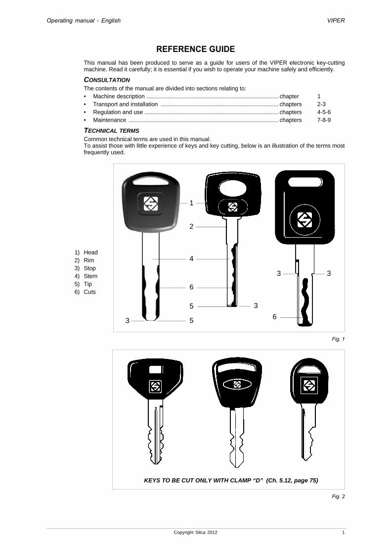
TECHNICAL TERMS
Common technical terms are used in this manual.To assist those with little experience of keys and key cutting, below is an illustration of the terms most frequently used.
1) Head2) Rim3) Stop4) Stem5) Tip6) Cuts
Fig. 1
Fig. 2
1
2
4
5
5
6
3
3 3
63
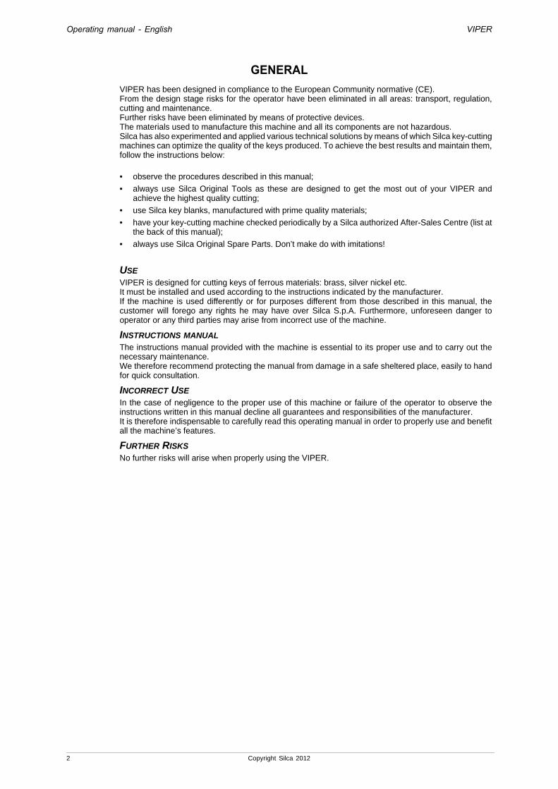
KEYS TO BE CUT ONLY WITH CLAMP “D” (Ch. 5.12, page 75)
Copyright Silca 2012 1
Operating manual - English VIPER
GENERALVIPER has been designed in compliance to the European Community normative (CE). From the design stage risks for the operator have been eliminated in all areas: transport, regulation, cutting and maintenance.Further risks have been eliminated by means of protective devices.The materials used to manufacture this machine and all its components are not hazardous. Silca has also experimented and applied various technical solutions by means of which Silca key-cutting machines can optimize the quality of the keys produced. To achieve the best results and maintain them, follow the instructions below:
• observe the procedures described in this manual;
• always use Silca Original Tools as these are designed to get the most out of your VIPER and achieve the highest quality cutting;
• use Silca key blanks, manufactured with prime quality materials;
• have your key-cutting machine checked periodically by a Silca authorized After-Sales Centre (list at the back of this manual);
• always use Silca Original Spare Parts. Don’t make do with imitations!
USE
VIPER is designed for cutting keys of ferrous materials: brass, silver nickel etc.It must be installed and used according to the instructions indicated by the manufacturer.If the machine is used differently or for purposes different from those described in this manual, the customer will forego any rights he may have over Silca S.p.A. Furthermore, unforeseen danger to operator or any third parties may arise from incorrect use of the machine.
INSTRUCTIONS MANUAL
The instructions manual provided with the machine is essential to its proper use and to carry out the necessary maintenance.We therefore recommend protecting the manual from damage in a safe sheltered place, easily to hand for quick consultation.
INCORRECT USE
In the case of negligence to the proper use of this machine or failure of the operator to observe the instructions written in this manual decline all guarantees and responsibilities of the manufacturer.It is therefore indispensable to carefully read this operating manual in order to properly use and benefit all the machine’s features.
FURTHER RISKS
No further risks will arise when properly using the VIPER.
2 Copyright Silca 2012

Operating manual - English VIPER
PROTECTION AND SAFETY PRECAUTIONS FOR THE OPERATOR
VIPER is entirely built in compliance to the Machine Directives. The operations for which it has been designed are easily carried out with no risk to the operator.The adoption of general safety precautions and observance of the instructions provided by the manufacturer in this manual eliminate all human error, unless deliberate.VIPER is designed with features which make it completely safe in all its parts.
• Power supplyVIPER is supplied with electrical power by means of an earthed plug and differential switch.• Start-upThe machine is turned on by means of a master switch that is located on the back side.• MaintenanceThe operations to regulate, service, repair and clean the machine are structured in the simplest and safest way possible. Parts that the operator can dismount cannot be incorrectly replaced therefore avoiding any risks.• Machine identificationThe machine is provided with an identification label which includes the machine’s serial number (fig. 3).
Fig. 3
(*) see Ch. 8 "DISPOSING OF MACHINE", page 101.
Copyright Silca 2012 3

Operating manual - English VIPER
1 MACHINE DESCRIPTIONVIPER is an electronic machine operating on two axes with controlled movement. Accurately studied, it adds a high degree of precision to operating speed and ease of use.VIPER can be used in 3 different ways:• entering the cuts directly• entering the key code by means of the machine keypad• reading the key with the decoder installed on the machine
Fig. 4
1.1 MAIN CHARACTERISTICS • MovementsMovement of the 2 axes (top, bottom) operates on ball screws activated by step motors, on rectified roller guides.• ClampUniversal standard clamp with 3 positions.• Working toolDedicated cutter in HSS (high speed steel) for traced keys.Tools are quick and easy to replace.• DisplayRetro-illuminated and placed on the front of the machine.Display with 4 rows of 20 characters each.Its technical features and positioning make it highly practical in use.
4 Copyright Silca 2012

Operating manual - English VIPER
1.2 SAFETY• Protective shieldThe transparent protective shield is designed to cover the working parts as fully as possible, making them completely safe.The shield (V) (fig. 5, page 6) must be raised in order to fit keys for cutting or carry out other operations.Raising of the shield is controlled by a microswitch and disactivates the operating and movement functions, including the cutter. A special message appears on the display to warn that the shield is not closed. To re-start the work cycle, replace the shield in its original position and press the START button on the machine keypad.• Emergency stopThe red emergency button (P) (fig. 5, page 6), placed on the right-hand side of the machine is used to stop it immediately in the event of faulty operation or danger for the operator. When the cause of the emergency has been eliminated, turn the button clockwise 45° to disactivate it.
Note: the operator is responsible for keeping the area around the button clear so that it can be reached as quickly as possible.
IMPORTANT: keys in anodized aluminium, plastic or any other ma terial that has no electrical conductivity CANNOT BE DECODED!For keys of this type use only the “key-cutting” function.
Copyright Silca 2012 5
Operating manual - English VIPER
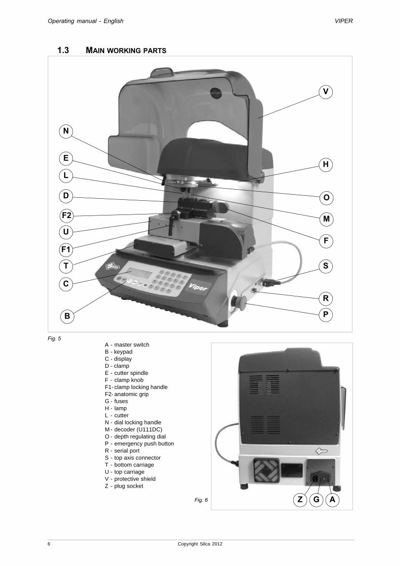
1.3 MAIN WORKING PARTS
Fig. 5A - master switchB - keypadC - display D - clampE - cutter spindleF - clamp knobF1- clamp locking handleF2- anatomic gripG - fusesH - lampL - cutterN - dial locking handleM - decoder (U111DC)O - depth regulating dialP - emergency push buttonR - serial portS - top axis connectorT - bottom carriageU - top carriageV - protective shieldZ - plug socket
Fig. 6
O
N
L
E
D
U
T
C
B
F
H
S
R
P
V
F1
F2 M
Z G A
6 Copyright Silca 2012
Operating manual - English VIPER
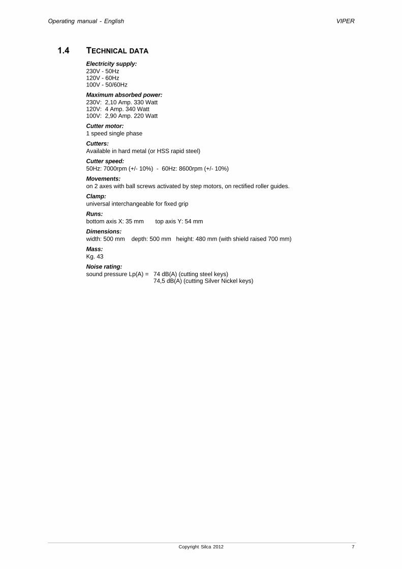
1.4 TECHNICAL DATA
Electricity supply:230V - 50Hz120V - 60Hz100V - 50/60Hz
Maximum absorbed power:230V: 2,10 Amp. 330 Watt120V: 4 Amp. 340 Watt100V: 2,90 Amp. 220 Watt
Cutter motor:1 speed single phase
Cutters:Available in hard metal (or HSS rapid steel)
Cutter speed:50Hz: 7000rpm (+/- 10%) - 60Hz: 8600rpm (+/- 10%)
Movements:on 2 axes with ball screws activated by step motors, on rectified roller guides.
Clamp:universal interchangeable for fixed grip
Runs:bottom axis X: 35 mm top axis Y: 54 mm
Dimensions:width: 500 mm depth: 500 mm height: 480 mm (with shield raised 700 mm)
Mass:Kg. 43
Noise rating:sound pressure Lp(A) = 74 dB(A) (cutting steel keys)
74,5 dB(A) (cutting Silver Nickel keys)
Copyright Silca 2012 7
Operating manual - English VIPER
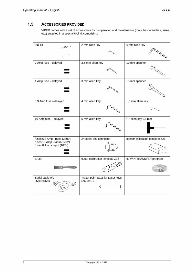
1.5 ACCESSORIES PROVIDEDVIPER comes with a set of accessories for its operation and maintenance (tools, hex wrenches, fuses, etc.) supplied in a special tool kit comprising:
tool kit 2 mm allen key 6 mm allen key
2 Amp fuse – delayed 2,5 mm allen key 10 mm spanner
4 Amp fuse – delayed 3 mm allen key 13 mm spanner
6,3 Amp fuse – delayed 4 mm allen key 1,5 mm allen key
10 Amp fuse – delayed 5 mm allen key “T” allen key 2,5 mm
fuses 6,3 Amp - rapid (230V)fuses 10 Amp - rapid (120V)fuses 8 Amp - rapid (100V)
Z4 serial test connector sensor calibration template Z21
Brush cutter calibration template Z22 cd WIN-TRANSFER program
Serial cable 9/9D709281ZB
Tracer point U111 for Laser keysD929921ZR
8 Copyright Silca 2012
Operating manual - English VIPER
2 TRANSPORTThe key-cutting machine is easily transported and is not dangerous to handle. The packed machine should be carried by at least two people.
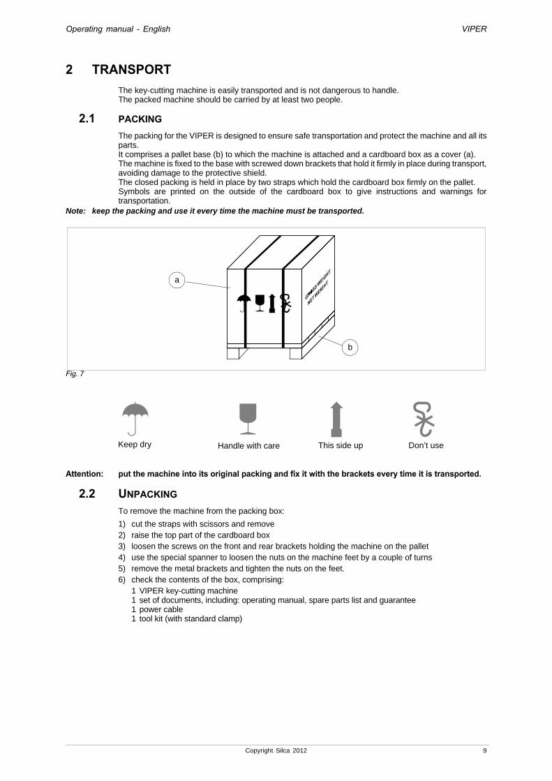
2.1 PACKINGThe packing for the VIPER is designed to ensure safe transportation and protect the machine and all its parts.It comprises a pallet base (b) to which the machine is attached and a cardboard box as a cover (a).The machine is fixed to the base with screwed down brackets that hold it firmly in place during transport, avoiding damage to the protective shield.The closed packing is held in place by two straps which hold the cardboard box firmly on the pallet.Symbols are printed on the outside of the cardboard box to give instructions and warnings for transportation.
Note: keep the packing and use it every time the machine must be transported.
Fig. 7
Attention: put the machine into its original packing and fix it with the brackets every time it is transported.
2.2 UNPACKINGTo remove the machine from the packing box:
1) cut the straps with scissors and remove2) raise the top part of the cardboard box3) loosen the screws on the front and rear brackets holding the machine on the pallet4) use the special spanner to loosen the nuts on the machine feet by a couple of turns5) remove the metal brackets and tighten the nuts on the feet.6) check the contents of the box, comprising:
1 VIPER key-cutting machine1 set of documents, including: operating manual, spare parts list and guarantee1 power cable1 tool kit (with standard clamp)
a
b
Keep dry This side upHandle with care Don’t use
Copyright Silca 2012 9

Operating manual - English VIPER
2.3 MACHINE HANDLINGWhen the VIPER has been unpacked, place it directly on its workbench; this operation must be carried out by at least two people.
Attention: when lifting the machine hold it firmly by the base, and no other part (fig. 8/A).Never lift the machine by holding the keypad stand (fig. 8/B).
Fig. 8/A
Fig. 8/B
YES
NO!
10 Copyright Silca 2012
Operating manual - English VIPER
3 MACHINE INSTALLATION AND PREPARATIONThe key-cutting machine can be installed by the purchaser and does not require any special skills.It is supplied ready for use and does not need to be set up. However, some checks and preparation for use have to be carried out by the operator.
3.1 CHECKING FOR DAMAGEVIPER is solid and compact and will not normally damage if transport, unpacking and installation have all been carried out according to the instructions in this manual. However, it is always advisable to check that the machine has not suffered any damage.
3.2 ENVIRONMENTAL CONDITIONSTo ensure that the best use is made of the key-cutting machine, bear in mind the following parameters for its location: the area should be well-aired and dry.The ideal conditions for the machine are: temperature between 10°C and 40°C; relative humidity: approx60%
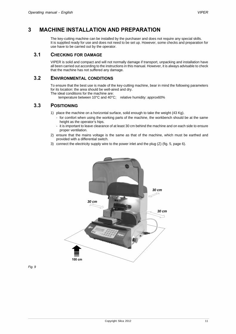
3.3 POSITIONING1) place the machine on a horizontal surface, solid enough to take the weight (43 Kg).
- for comfort when using the working parts of the machine, the workbench should be at the same height as the operator’s hips.
- it is important to leave clearance of at least 30 cm behind the machine and on each side to ensure proper ventilation.
2) ensure that the mains voltage is the same as that of the machine, which must be earthed and provided with a differential switch.
3) connect the electricity supply wire to the power inlet and the plug (Z) (fig. 5, page 6).
Fig. 9
100 cm
30 cm
30 cm
30 cm
Copyright Silca 2012 11

Operating manual - English VIPER
3.4 DESCRIPTION OF WORK STATIONThe machine needs only one operator, who has the following controls at his/her disposal (fig. 5, page 6):
• master switch placed on the back of the machine
• key positioning clamp
• keypad
• display
• emergency push button
3.5 GRAPHICSThe Plexiglas protective shield carries an adhesive warning label (fig. 10). This label must never be removed.
Fig. 10
3.6 SEPARATE PARTSThe standard clamp (fig. 11) is in the tool kit and not installed on the machine.Install as indicated in this operating manual (Ch. 4.4, page 18).
Attention: for the initial start-up DO NOT install the clamp UNTIL the axis clearing procedure has been carried out.
Fig. 11
Do not use compressed airfor cleaning
12 Copyright Silca 2012
Operating manual - English VIPER
4 REGULATION AND USE OF THE MACHINE4.1 KEYPAD AND FUNCTION KEYS
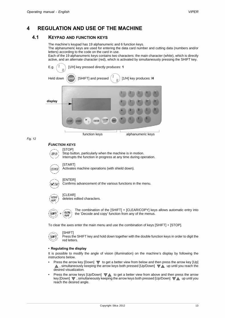
The machine’s keypad has 19 alphanumeric and 6 function keys.The alphanumeric keys are used for entering the data card number and cutting data (numbers and/or letters) according to the code on the card in use.Each of the 19 alphanumeric keys contains two characters: the main character (white), which is directly active, and an alternate character (red), which is activated by simultaneously pressing the SHIFT key.
E.g. [1/H] key pressed directly produces: 1
Held down [SHIFT] and pressed [1/H] key produces: H
Fig. 12
FUNCTION KEYS
[STOP] Stop button, particularly when the machine is in motion.Interrupts the function in progress at any time during operation.
[START]Activates machine operations (with shield down).
[ENTER]Confirms advancement of the various functions in the menu.
[CLEAR]deletes edited characters.
The combination of the [SHIFT] + [CLEAR/COPY] keys allows automatic entry into the ‘Decode and copy’ function from any of the menus.
To clear the axes enter the main menu and use the combination of keys [SHIFT] + [STOP].
[SHIFT]Press the SHIFT key and hold down together with the double function keys in order to digit the red letters.
• Regulating the displayIt is possible to modify the angle of vision (illumination) on the machine’s display by following the instructions below.
• Press the arrow key [Down] to get a better view from below and then press the arrow key [Up] , simultaneously keeping the arrow keys both pressed [Up/Down] up until you reach the
desired visualization.
• Press the arrow keys [Up/Down] to get a better view from above and then press the arrow key [Down] , simultaneously keeping the arrow keys both pressed [Up/Down] up until you reach the desired angle.
SHIFT
display
function keys alphanumeric keys
+
Copyright Silca 2012 13

Operating manual - English VIPER
4.2 USE OF THE CLAMPThe machine is provided with the standard clamp shown in fig. 13.
Fig. 13
Fig. 14As illustrated in fig. 13, the clamp has 3 fixed plates (A-left; B/C centre; right) and 1 mobile double plate. Two of the fixed plates (A e B/C) plus the mobile double plate can be replaced when worn.The clamp has 2 vertical cylindrical pins to detect/recognise the clamp by electric contact.The A clamp comes with 3 Stops (0-1-2) for keys to be decoded or cut with jaw A.The B clamp comes with 2 Stops (0-2) for keys to be decoded or cut with jaw BThe C clamp comes with 1 Stop (0) for keys to be decoded or cut with jaw C.The clamp has 3 position notches (Z) so that it can be easily accommodated in the required position (Clamp A, B or C).When the (F1) handle is loosened by at least one turn and the anatomic grip (F2) is pulled towards the front of the machine the clamp is released therefore can slide to the right or left.When the (F2) anatomic grip is released and the clamp is manually moved, the positioning device will lock the clamp into the first position notch it finds.When the clamp is in the required position (jaw A, B or C) the (F1) handle should be tightened.
Fig. 15
F
Z
A
B-C
mobileplates
220
1Stop 1Stop 2
Stop 0 Stop 0
F2
F1
F
14 Copyright Silca 2012
Operating manual - English VIPER
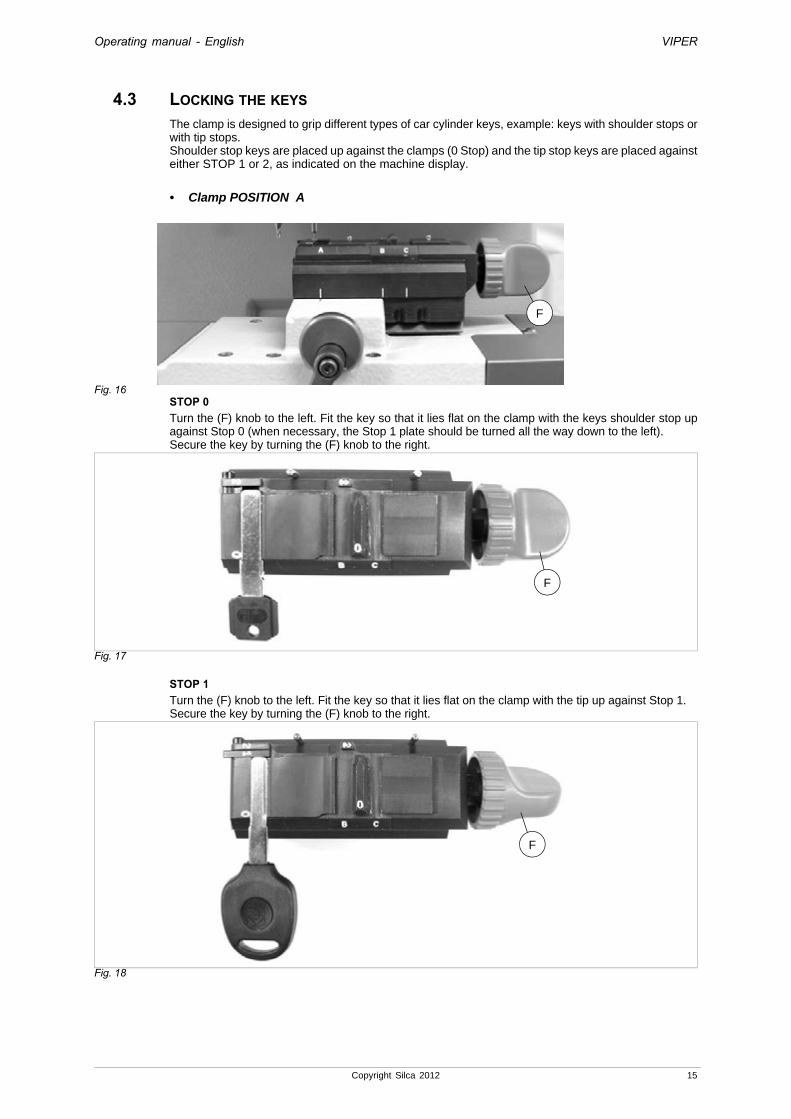
4.3 LOCKING THE KEYS The clamp is designed to grip different types of car cylinder keys, example: keys with shoulder stops or with tip stops.Shoulder stop keys are placed up against the clamps (0 Stop) and the tip stop keys are placed against either STOP 1 or 2, as indicated on the machine display.
• Clamp POSITION A
Fig. 16STOP 0 Turn the (F) knob to the left. Fit the key so that it lies flat on the clamp with the keys shoulder stop up against Stop 0 (when necessary, the Stop 1 plate should be turned all the way down to the left).Secure the key by turning the (F) knob to the right.
Fig. 17
STOP 1Turn the (F) knob to the left. Fit the key so that it lies flat on the clamp with the tip up against Stop 1.Secure the key by turning the (F) knob to the right.
Fig. 18
F
F
F
Copyright Silca 2012 15

Operating manual - English VIPER
STOP 2Turn the (F) knob to the left. Fit the key so that it lies flat on the clamp with the tip up against Stop 2 (to do this the Stop 1 plate must be turned left and downwards).Secure the key by turning the (F) knob to the right.
Fig. 19
• Clamp POSITION B
Fig. 20STOP 0 Turn the (F) knob to the right. Fit the key so that it lies flat on the clamp with the tip up against Stop 0.Secure the key by turning the (F) knob to the left.
STOP 2Turn the (F) knob to the right. Fit the key so that it lies flat on the clamp with the tip up against Stop 2.Secure the key by turning the (F) knob to the left.
Fig. 21
F
F
F
16 Copyright Silca 2012
Operating manual - English VIPER
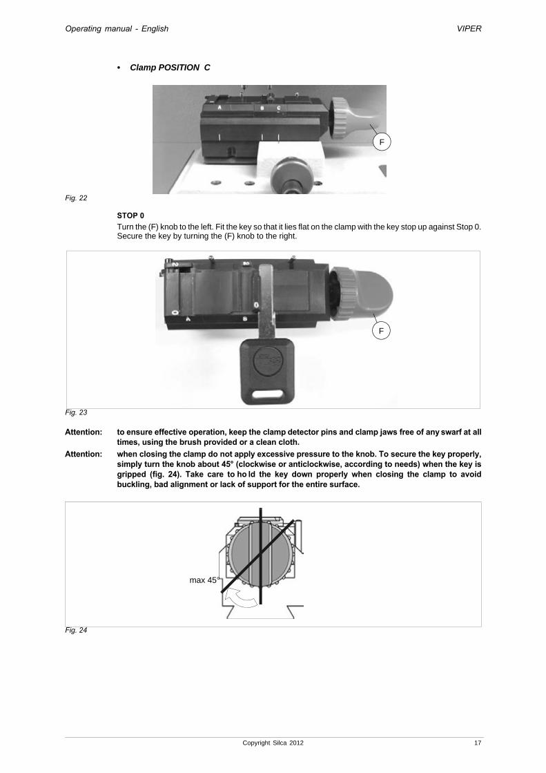
• Clamp POSITION C
Fig. 22
STOP 0 Turn the (F) knob to the left. Fit the key so that it lies flat on the clamp with the key stop up against Stop 0.Secure the key by turning the (F) knob to the right.
Fig. 23
Attention: to ensure effective operation, keep the clamp detector pins and clamp jaws free of any swarf at all times, using the brush provided or a clean cloth.
Attention: when closing the clamp do not apply excessive pressure to the knob. To secure the key properly, simply turn the knob about 45° (clockwise or anticlockwise, according to needs) when the key is gripped (fig. 24). Take care to ho ld the key down properly when closing the clamp to avoid buckling, bad alignment or lack of support for the entire surface.
Fig. 24
F
F
max 45°
Copyright Silca 2012 17

Operating manual - English VIPER
4.4 FITTING THE CLAMP TO THE MACHINETo remove the clamp:- Loosen the (F1) handle by one turn and pull the (F2) anatomic grip towards the operator (front of the
machine). This releases the clamp so that it can slide to the right or left along the dovetail groove and be removed.
To install the clamp on the machine:Attention: at initial start-up DO NOT CONTINUE. Zero out the axes and remove the tie wrap (H3) (fig. 26).
Press both the SHIFT + STOP buttons to continue with the zero positioning.The axes are automatically zeroed out. First the display shows:
Then it returns to the initial menu.You can then fit the clamp to the machine.
Loosen the (F1) handle by at least one turn and pull the (F2) anatomic grip towards the front of the machine to be able to slide the clamp into the dovetail groove. The clamp has 3 positioning notches that correspond to the 3 cutting positions on the clamp (Jaw A, B or C). When the anatomic grip is released and the clamp is manually moved (to the right or left) the positioning device in the groove will lock the clamp into the first notch it finds. When the clamp is in the required position (Jaw A, B or C), tighten the (F1) handle.
These instructions refer exclusively to the clamp provided.
Fig. 25
Fig. 26
P o s i t i o n i n gi n p r o g r e s s !
F2
F1
F
H3
18 Copyright Silca 2012

Operating manual - English VIPER
4.5 CUTTERThe cutter provided is the “W101” that is suitable for cutting laser (sidewinder) type keys.
Attention: the cutter to be used is shown on the display. The type of cutter to fit is identified with the letter H (HSS) or W (hard metal).
4.6 CHANGING THE CUTTER AND/OR THE TRACER POINTTo remove the tracer point U111 or the cutter W101 from the spindle, proceed as follows:- raise the protective shield.
- turn the cutter spindle (by hand) in order to reach the tool-locking grub screw (E1) (fig. 28).
- with one hand hold the cutter or the tracer point that needs to be removed and with the other use a 2,5mm hex wrench to loosen the (E1) grub screw.
- remove the tool (cutter or tracer point).
To install cutter or tracer point, proceed as follows:- raise the protective shield.
- insert the tool all the way up into the spindle.
- holding the tool with one hand, use the other to tighten the (E1) grub screw with the 2.5 mm hex wrench.
Fig. 27
Fig. 28
tracer point U111 cutter W101
E1 E1
tracer point cutterW101U111
decoderU111DC
Copyright Silca 2012 19

Operating manual - English VIPER
5 OPERATING GUIDEINTRODUCTION
The Operating Guide below explains how to use the VIPER.All operations are explained step by step for easy accurate use of the key-cutting machine.
See Ch. 5.12 to cut flat keys (vehicle) with clamp “D”.
5.1 SYMBOLS AND TERMINOLOGYTo facilitate comprehension, below is a glossary of the most commonly used symbols and terms referring to keys or the key-cutting machine.Reference will be made to the symbols and terms on this page in the following pages, but comprehension will be better if they are read here.
Cutter W101... = the letter indicates the material (W = carbide), the number its conformation (rake, base of cut, …)
Decoder U111DC = standard decoder for decoding (to the right of the cutter)
Tracer point U111 = tracer point for gauging the clamps (and decoding) to fit in the place of the cutter when the standard decoder is disabled
Clamp A = standard clamp provided with the VIPER key-cutting machine, positioned to operate with jaw A
Clamp B = standard clamp provided with the VIPER key-cutting machine, positioned to operate with jaw B.
Clamp C = standard clamp provided with the VIPER key-cutting machine, positioned to operate with jaw C.
System/lock = all the information comprised in the key to be cutE.g.: see examples of symbol tables (below)
…… = each dot corresponds to each cut on the key
[n°] = position of the cut. The value changes when the cursor is moved (R/H arrow) along the combination
Silca Serial Number (SSN) = serial number assigned by Silca to every system/lock. Found in Silca key catalogues or Silca software programs
MFG (Manufacturer) = the make of the cylinder or vehicle for the key to be cutE.g.: MERCEDES (make of vehicle)
Sides = the cut sides of the key, identified asSide A (1st side)Side B (2nd side)
Axis = row of cuts on the key
13
S26
HU55P
A
B
20 Copyright Silca 2012
Operating manual - English VIPER
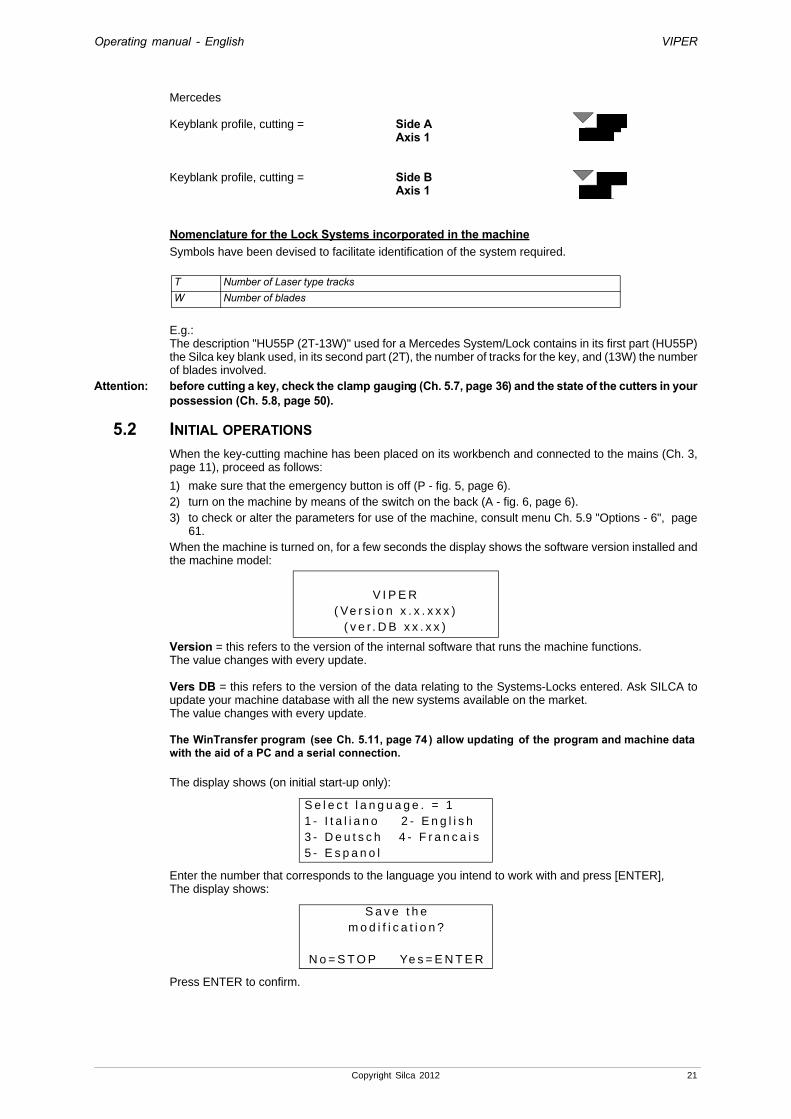
Mercedes
Keyblank profile, cutting = Side AAxis 1
Keyblank profile, cutting = Side BAxis 1
Nomenclature for the Lock Systems incorporated in the machineSymbols have been devised to facilitate identification of the system required.
E.g.:The description "HU55P (2T-13W)" used for a Mercedes System/Lock contains in its first part (HU55P) the Silca key blank used, in its second part (2T), the number of tracks for the key, and (13W) the number of blades involved.
Attention: before cutting a key, check the clamp gauging (Ch. 5.7, page 36) and the state of the cutters in your possession (Ch. 5.8, page 50).
5.2 INITIAL OPERATIONSWhen the key-cutting machine has been placed on its workbench and connected to the mains (Ch. 3, page 11), proceed as follows:
1) make sure that the emergency button is off (P - fig. 5, page 6).2) turn on the machine by means of the switch on the back (A - fig. 6, page 6).3) to check or alter the parameters for use of the machine, consult menu Ch. 5.9 "Options - 6", page
61.When the machine is turned on, for a few seconds the display shows the software version installed and the machine model:
Version = this refers to the version of the internal software that runs the machine functions.The value changes with every update.
Vers DB = this refers to the version of the data relating to the Systems-Locks entered. Ask SILCA to update your machine database with all the new systems available on the market. The value changes with every update.
The WinTransfer program (see Ch. 5.11, page 74 ) allow updating of the program and machine data with the aid of a PC and a serial connection.
The display shows (on initial start-up only):
Enter the number that corresponds to the language you intend to work with and press [ENTER],The display shows:
Press ENTER to confirm.
T Number of Laser type tracksW Number of blades
V I P E R( Ve r s i o n x . x . x x x )
( v e r . D B x x . x x )
S e l e c t l a n g u a g e . = 11 - I t a l i a n o 2 - E n g l i s h3 - D e u t s c h 4 - F r a n c a i s5 - E s p a n o l
S a v e t h em o d i f i c a t i o n ?
N o = S T O P Ye s = E N T E R
Copyright Silca 2012 21
Operating manual - English VIPER
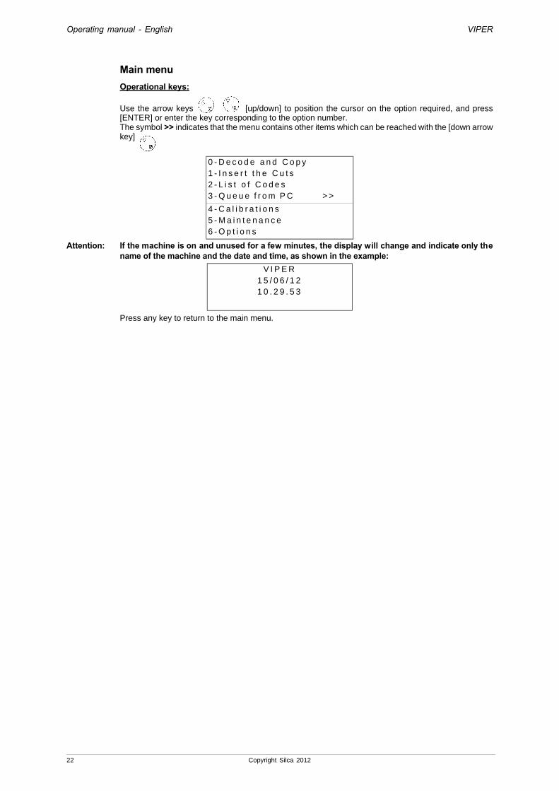
Main menuOperational keys:
Use the arrow keys [up/down] to position the cursor on the option required, and press [ENTER] or enter the key corresponding to the option number.The symbol >> indicates that the menu contains other items which can be reached with the [down arrow key]
Attention: If the machine is on and unused for a few minutes, the display will change and indicate only the name of the machine and the date and time, as shown in the example:
Press any key to return to the main menu.
0 - D e c o d e a n d C o p y1 - I n s e r t t h e C u t s2 - L i s t o f C o d e s3 - Q u e u e f r o m P C > >
4 - C a l i b r a t i o n s 5 - M a i n t e n a n c e6 - O p t i o n s
V I P E R1 5 / 0 6 / 1 21 0 . 2 9 . 5 3
22 Copyright Silca 2012

Operating manual - English VIPER
5.3 DECODING AND COPY - 0IMPORTANT: keys in anodized aluminium, plastic or any other ma terial that has no electrical conductivity CANNOT BE DECODED!For keys of this type use only the “key-cutting” functionBelow is a description of all the different stages for decoding and cutting a key. Choose the function from the main menu by placing the cursor on “0-Decode and Copy”.
Press ENTER, the display will show:
Make a search by SSN or MFG (see Ch. 5.1 "Symbols and terminology", page 20).
Example for: HONDA
• press the key [right-hand arrow] to place the cursor next to the “MFG” field.It is not necessary to enter the enti re name, the first letters are sufficient; the name of the M AKE closest in alphabetical order appears automatically;
• the arrow keys [up/down] can be used to scroll the successive makes in alphabetical order.
• Use the [CLEAR] key to delete the text entered.
• the last line in the window gives the results of the search:- “[11] List = ENTER”: means that 11 Silca Serial Numbers (SSN) have been found; press [EN-
TER] to see the list.
Note: the system requires clamp “D” if the letter D appears in front of a description.For example, with the pointer in position 10:• To view further information on the SSNs found, hold down the key [right-hand arrow]. For
example, with the pointer in position 1:
Press ENTER to continue, the display will show:
0 - D e c o d e a n d C o p y1 - I n s e r t t h e C u t s2 - L i s t o f C o d e s3 - Q u e u e f r o m P C > >
4 - C a l i b r a t i o n s5 - M a i n t e n a n c e6 - O p t i o n s
S S N = ( D e c o d . )M F G == >
S S N = ( D e c o d . )M F G = H O N= > H O N D A[ 1 1 ] L i s t = E N T E R
H O N D A [ 1 1 ]9 : 1 9 9 0 H O N D A1 0 : ( 1 . 4 1 ) M a i n ( 4 T - 6 )1 1 : ( 1 . 4 1 ) S u b ( 4 T - 6 W )
S i l c a N r . 5 8 2( 1 . 4 1 ) M a i n ( 4 T - 6 W )1 : A C U R A2 : H O N D A
D E C O D EC l a m p : A P o s . : 2T r a c e r D i a l : 5
[ S TA R T ]
?
?
Copyright Silca 2012 23

Operating manual - English VIPER
- Raise the safety shield, loosen the handle (N) and turn the depth regulating (O) dial so that the number 5 is aligned with the spindle support reference red notch (you should feel a click). Lock the lever (N).
- Loosen the (F1) handle by one turn and pull the (F2) anatomic grip towards the operator. This releases the clamp so that it can slide to the right or left. Release the anatomic grip and move the clamp manually. The positioning device will lock the clamp in the clamp reference notch. When the clamp is in position (Clamp A) tighten the (F1) handle.
- Turn the (F) knob. to the left. Fit the key to be decoded into jaw A so that it lies flat against the clamp with the tip up against Stop 2 (to do this the Stop 1 plate must be flipped left and downwards). Secure the key by turning the (F) knob to the right.
Fig. 29Pull the shield down and press START to begin decoding. If the protective shield is not closed, the following message appears:
When the shield is lowered, the following message appears:
Press START to continue; first the display will show the message:
then:
at the end of the procedure the display will show the message (example):
C l o s es h i e l d !
C o n t i n u e ?
N o = S T O P Ye s = S TA R T
D E C O D I N G I N P R O G R E S SS i d e : AA x i s : 1
D E C O D I N G I N P R O G R E S S
S i d e : AA x i s : 2
A x i s : 1 o f 2S i d e s : A B1 3 3 6 4 2( 1 2 3 4 5 6 ) [ 6 ]
F1
F2
F
N
O
24 Copyright Silca 2012

Operating manual - English VIPER
Press the arrow key [down] and the display will indicate the cuts corresponding to the second axis (example):
ATTENTION- press the key [arrow right] to move the pointer (on the same axis) into the various cutting
positions.- Press the key [arrow up] to eliminate the cuts indicated by the pointer (an empty space is
created); the cutting positions remain unaltered [6].- Press the key (CLEAR/COPY) to eliminate some cuts (the machine considers consecutive
cuts and not empty spaces) and reduce the cutting positions [5].
Press ENTER to proceed with the cutting operations. The display will show:
Raise the safety shield, loosen the (F) knob and remove the original key. Fit the key blank into the clamp (clamp A and Stop 2) and lock the (F) knob.Lower the safety shield.If the number of keys to be cut is different from 1, use the alphanumerical keys on the keyboard to enter the number of keys required (pieces) [1-255].
Attention: the operator is responsible for installing the right cutter as there is no electronic device to warn of any errors!!!Press START to begin cutting.
During the cutting operation the following message appears:
The value ‘Axis: 1’ appears during cutting of the 1st axis.
Going on to cut axis 2, the following message appears:
When side A has been cut the following message appears:
Raise the safety shield, loosen the (F) knob remove the key, turn it 180°, replace on the clamp (clamp A and Stop 2) and lock the (F) knob.Lower the safety shield and press START.
A x i s : 2 o f : 2S i d e s : A B2 3 4 2 4 2( 1 2 3 4 5 6 ) [ 6 ]
C l a m p : A P o s . : 2C u t t e r : W 1 0 1 D i a l : 5F = b r a s sP c s = 1 / 1 [ S T A R T ]
C l a m p : A P o s . : 2 C u t t e r : W 1 0 1 D i a l : 5 F = b r a s s P c s = 1 / 1 [ S T A R T ]
C U T T I N G I N P R O G R E S SC o p y : 1 o f : 1
S i d e : A A x i s : 1B r a s s
C U T T I N G I N P R O G R E S SC o p y : 1 o f : 1
S i d e : A A x i s : 2B r a s s
C l a m p : A P o s . : 2 C u t t e r : W 1 0 1 D i a l : 5 F = b r a s s P c s = 1 / 1 [ S T A R T ]
Copyright Silca 2012 25

Operating manual - English VIPER
The value ‘Axis: 1’ appears during cutting of the 1st axis.
Going on to cut axis 2, the following message appears:
When the cutting operation is complete, the following message appears:
Press [ENTER] to proceed with another copy.
Press [STOP] to end the operation.
C U T T I N G I N P R O G R E S SC o p y : 1 o f : 1
S i d e : B A x i s : 1B r a s s
C U T T I N G I N P R O G R E S SC o p y : 1 o f : 1
S i d e : B A x i s : 2B r a s s
C o p y : 1 o f : 1f i n i s h e d !
M o r e c o p i e s ?N o = S T O P Ye s = E N T E R
26 Copyright Silca 2012

Operating manual - English VIPER
5.4 INSERT THE CUTS - 1Below is a description of all the different stages for cutting a key when the SSN is known, or the make associated to the Lock System.Choose the function from the main menu by placing the cursor on “1 - Insert the Cuts”.
Note: make a search by SSN or Make (see Ch. 5.1 "Symbols and terminology", page 20).
Example for HONDA:
• Press the key [right-hand arrow] to place the cursor next to “MFG”.It is not necessary to enter the enti re name, the first letters are sufficient; the name of the M AKE closest in alphabetical order appears automatically;
• the arrow keys [up-down] can be used to scroll the successive MAKES in alphabetical order.
• use the [CLEAR] key to delete the text entered.
• The last line in the window shows the result of the search:- “[11]) List = ENTER”: means that 11 SSNs have been found; press [ENTER] to see the list.
Note: the system requires clamp “D” if the letter D appears in front of a description.
• To view further information on the SSNs found, hold down the key [right arrow].
Use [down arrow key] to go on to Axis 2.
Use the alphanumerical keys to enter only the symbols indicated in brackets (1, 2, 3, 4, 5, 6,) which correspond to the cutting depths admitted for the chosen key.
- If a different symbol is entered, a long warning ‘beep’ will sound.
- To skip cuts (empty cuts or gaps between cuts) press [up arrow key].
- The figure in square brackets [1] corresponds to the cutting position (pitch;
- To move the cursor horizontally press [right arrow];
(when the end of the line is reached the cursor automatically returns to its starting position).To view or enter cuts for the various key axes, press [down arrow key].
0 - D e c o d e a n d C o p y1 - I n s e r t t h e C u t s2 - L i s t o f C o d e s3 - Q u e u e f r o m P C > >
4 - C a l i b r a t i o n s 5 - M a i n t e n a n c e6 - O p t i o n s
S S N = ( C u t )M F G = H O N= > H O N D A[ 1 1 ] L i s t = E n t e r
H O N D A [ 1 1 ]9 : 1 9 9 0 H O N D A1 0 : ( 1 . 4 1 ) M a i n ( 4 T - 6 )1 1 : ( 1 . 4 1 ) S u b ( 4 T - 6 W )
A x i s : 1 o f : 2S i d e s : A B. . . . . .( 1 2 3 4 5 6 ) [ 1 ]
A x i s : 2 o f : 2S i d e s : A B. . . . . .( 1 2 3 4 5 6 ) [ 1 ]
?
?
?
Copyright Silca 2012 27
Operating manual - English VIPER
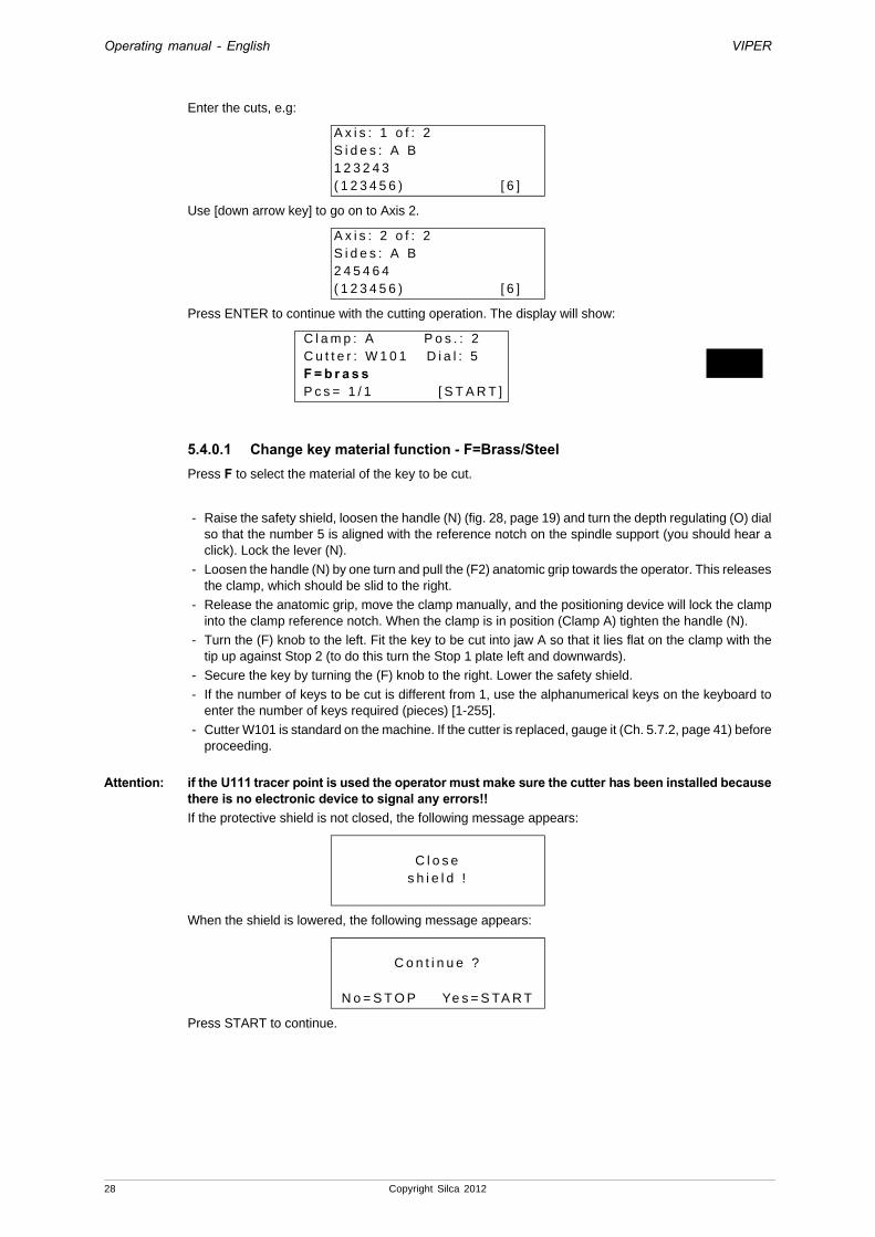
Enter the cuts, e.g:
Use [down arrow key] to go on to Axis 2.
Press ENTER to continue with the cutting operation. The display will show:
5.4.0.1 Change key material function - F=Brass/SteelPress F to select the material of the key to be cut.
- Raise the safety shield, loosen the handle (N) (fig. 28, page 19) and turn the depth regulating (O) dial so that the number 5 is aligned with the reference notch on the spindle support (you should hear a click). Lock the lever (N).
- Loosen the handle (N) by one turn and pull the (F2) anatomic grip towards the operator. This releases the clamp, which should be slid to the right.
- Release the anatomic grip, move the clamp manually, and the positioning device will lock the clamp into the clamp reference notch. When the clamp is in position (Clamp A) tighten the handle (N).
- Turn the (F) knob to the left. Fit the key to be cut into jaw A so that it lies flat on the clamp with the tip up against Stop 2 (to do this turn the Stop 1 plate left and downwards).
- Secure the key by turning the (F) knob to the right. Lower the safety shield.
- If the number of keys to be cut is different from 1, use the alphanumerical keys on the keyboard to enter the number of keys required (pieces) [1-255].
- Cutter W101 is standard on the machine. If the cutter is replaced, gauge it (Ch. 5.7.2, page 41) before proceeding.
Attention: if the U111 tracer point is used the operator must make sure the cutter has been installed because there is no electronic device to signal any errors!!If the protective shield is not closed, the following message appears:
When the shield is lowered, the following message appears:
Press START to continue.
A x i s : 1 o f : 2S i d e s : A B1 2 3 2 4 3( 1 2 3 4 5 6 ) [ 6 ]
A x i s : 2 o f : 2S i d e s : A B2 4 5 4 6 4( 1 2 3 4 5 6 ) [ 6 ]
C l a m p : A P o s . : 2 C u t t e r : W 1 0 1 D i a l : 5 F = b r a s s P c s = 1 / 1 [ S T A R T ]
C l o s es h i e l d !
C o n t i n u e ?
N o = S T O P Ye s = S TA R T
28 Copyright Silca 2012
Operating manual - English VIPER
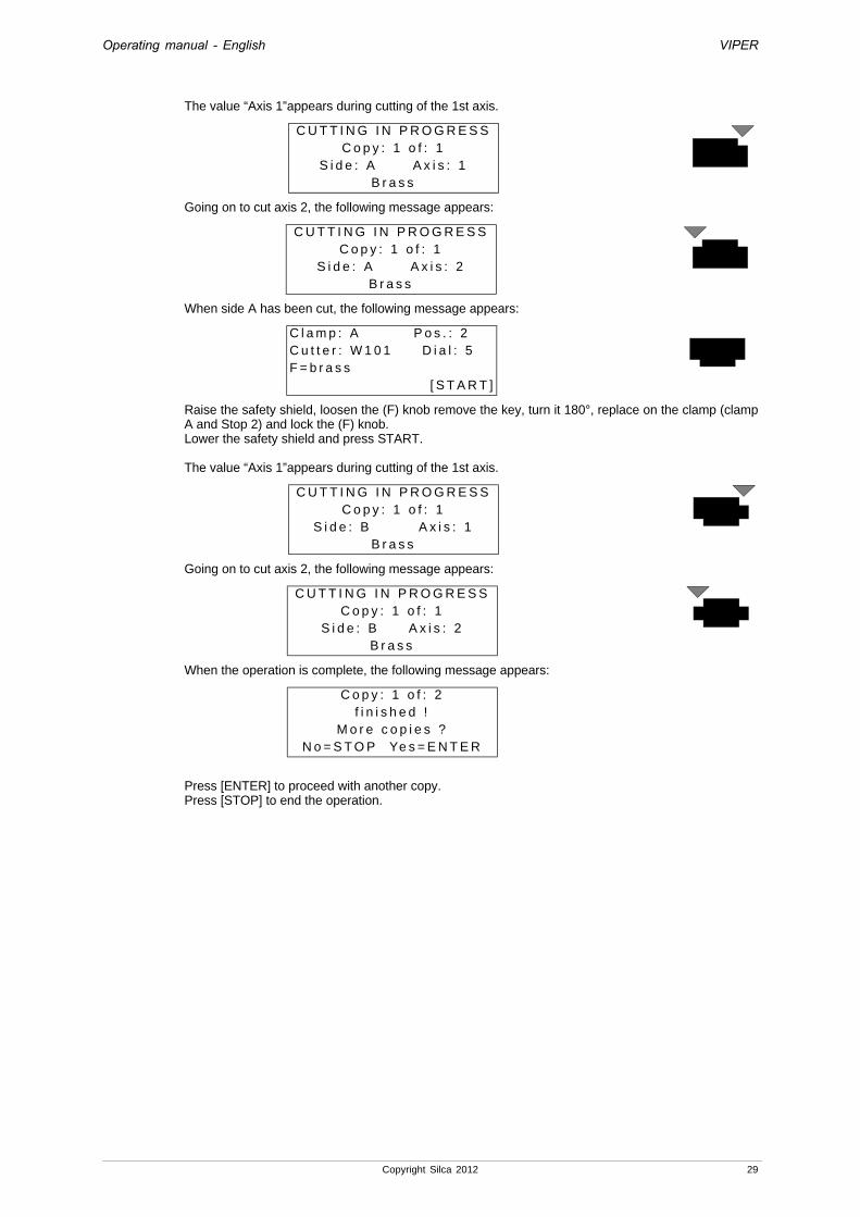
The value “Axis 1”appears during cutting of the 1st axis.
Going on to cut axis 2, the following message appears:
When side A has been cut, the following message appears:
Raise the safety shield, loosen the (F) knob remove the key, turn it 180°, replace on the clamp (clamp A and Stop 2) and lock the (F) knob.Lower the safety shield and press START.
The value “Axis 1”appears during cutting of the 1st axis.
Going on to cut axis 2, the following message appears:
When the operation is complete, the following message appears:
Press [ENTER] to proceed with another copy.Press [STOP] to end the operation.
C U T T I N G I N P R O G R E S SC o p y : 1 o f : 1
S i d e : A A x i s : 1B r a s s
C U T T I N G I N P R O G R E S SC o p y : 1 o f : 1
S i d e : A A x i s : 2B r a s s
C l a m p : A P o s . : 2C u t t e r : W 1 0 1 D i a l : 5F = b r a s s
[ S T A R T ]
C U T T I N G I N P R O G R E S SC o p y : 1 o f : 1
S i d e : B A x i s : 1B r a s s
C U T T I N G I N P R O G R E S SC o p y : 1 o f : 1
S i d e : B A x i s : 2B r a s s
C o p y : 1 o f : 2f i n i s h e d !
M o r e c o p i e s ?N o = S T O P Ye s = E N T E R
Copyright Silca 2012 29

Operating manual - English VIPER
5.5 LIST OF CODES - 2Use the items “Original Code” or key MAKE-USE from the “LIST OF CODES” menu to identify the SSNs that have a code table associated.When the SSN has been found, the key can be cut in the way described in Ch. 5.4 "Insert the Cuts - 1", page 27.Choose the function from the main menu by placing the cursor on “2- List of Codes”.Carry out the search by entering the code or Make (Ch. 5.1 "Symbols and terminology", page 20).
Example by Code: HA30055
• Press the key [right-hand arrow] to place the cursor next to the field “Code=”.
• Enter the code “HA30055”.
• The search finds only one series for MERCEDES with codes between HA/NA10001 and 30057.The display will show:
Searches for the code entered is made in all the series relating to the MAKES enabled. With standard settings the machine makes searches in all the series of codes. To filter searches for codes on the basis of given Lock Makes or Cars, follow the instructions on page 61 (ch. 5.9 "Options - 6" , 5.9.2 "Preferences", “Preselect Makes”). If the code entered belongs to a series but not to the group of makes selected, the message “Code not f ound” appears and the last line of the window shows the words “SHIFT + ?”. Press the keys [SHIFT] and [?] to temporarily exclude the filter and extend the search to all makes so that the result can be viewed without having to alter the settings for “Preselect Makes.
Press ENTER, the display will show:
• To view further information about the SSNs found, hold down the key [right arrow].
Note: the system requires clamp “D” if the letter D appears in front of a description.
There are now two possible choices:
1) proceed with [SHIFT+ENTER] in order to follow the complete flow and see the cutting data associated with the code entered. The cutting data is already entered and correspond to the code HA30055.
2) Proceed with [ENTER] in order to skip some of the data and get to the window preceding start of the cutting operation.
Lower the safety shield and press START.The display will show:
C o d e = H A 3 0 0 5 5M F G == > M E R C E D E SH A / N A 1 0 0 0 1 - 3 0 0 5 7 H U 5
C o d e = H A 3 0 0 5 51 : H A / N A 1 0 0 0 1 - 3 0 0 5 7 H
S i l c a N r : 2 6H U 5 5 P ( 2 T - 1 3 W )1 - M E R C E D E S
C l a m p : B P o s . : 2C u t t e r : W 1 0 1 D i a l : 6F = b r a s s P c s = 1 / 1 [ S T A R T ]
C U T T I N G I N P R O G R E S SC o p y : 1 o f : 1
S i d e : A A x i s : 1B r a s s
?
?
30 Copyright Silca 2012

Operating manual - English VIPER
When the axis has been cut the display will show:
Raise the safety shield, loosen the (F) knob remove the key, turn it 180°, replace on the clamp (clamp B and Stop 2) and lock the (F) knob. Lower the safety shield and press START.The display will show:
When the operation is complete the following message appears:
[ENTER] to continue with a new code.[STOP] to end the operation.
• after terminating the cutting operation and pressing [STOP], a new window appears to ask whether the user wishes to cut a new key from the same series but with a code different from the previous one, without repeating the search from the beginning:
• [CLEAR] to delete the existing code.
• Enter the new code to be cut.
• [ENTER] to continue and cut a new Code
• [STOP] to end the operation.
C l a m p : B P o s . : 2C u t t e r : W 1 0 1 D i a l : 6
F = b r a s s [ S TA R T ]
C U T T I N G I N P R O G R E S SC o p y : 1 o f : 1
S i d e : B A x i s : 1B r a s s
C o p y : 1 o f : 1f i n i s h e d !
M o r e c o p i e s ?N o = S T O P Ye s = E N T E R
N e w c o d e ? = H A 3 0 0 5 5
( H A / N A 1 0 0 0 1 - 3 0 0 5 7 )[ E N T E R ]
N e w c o d e ? = N A 1 0 0 0 5 2
( H A / N A 1 0 0 0 1 - 3 0 0 5 7 )[ E N T E R ]
Copyright Silca 2012 31

Operating manual - English VIPER
Example for TOYOTA
• Press the key [right-hand arrow] to place the cursor next to the “Code=” field.
It is not necessary to enter the full name, the first few letters are enough; the screen will automatically show the name of the MAKE closest in alphabetical order;
• use the arrows [up/down] to scroll the sequence of MAKES in alphabetical order.
• Use the [CLEAR] key to delete the text entered.
• Press ENTER to continue; the display will show the message:
Note: the system requires clamp “D” if the letter D appears in front of a description.
• To view further information about the SSNs found, hold down the key [right-hand arrow].Press ENTER to continue; the display will show the message:
Enter the new code to be cut.
• There are now two possible choices:
1) Proceed with [SHIFT+ENTER] to follow the complete flow and see the cutting data associated with the code entered. The cutting data is already entered and corresponds to the code 1000.
Use [down arrow key] to go on to Axis 2.
Press ENTER to continue.2) Proceed with [ENTER] to skip some of the data and get to the window preceding the start of the
cutting operation:Press ENTER to continue; the display will show the message:
Press START to continue.
C o d e =M F G == >
C o d e =M F G = T= > T O Y O T A0 0 0 1 - 5 0 0 0 T O Y 4 0 P ( 4 T )
M F G : T O Y O T A [ 0 1 ]1 : 0 0 0 1 - 5 0 0 0 T O Y 4 0 P
I n s e r t t h e c o d e =
( 0 0 0 1 - 5 0 0 0 )[ E N T E R ]
I n s e r t t h e c o d e = 1 0 0 0
( 0 0 0 1 - 5 0 0 0 )[ E N T E R ]
A x i s : 1 o f : 2S i d e s : A B2 4 2 4 2 3 4 2( 5 4 3 2 1 ) [ 8 ]
A x i s : 2 o f : 2S i d e s : A B3 4 3 1 2 2 4 4( 5 4 3 2 1 ) [ 8 ]
C l a m p : A P o s . : 2C u t t e r : W 1 0 1 D i a l : 6F = b r a s s
[ S TA R T ]
?
?
32 Copyright Silca 2012
Operating manual - English VIPER
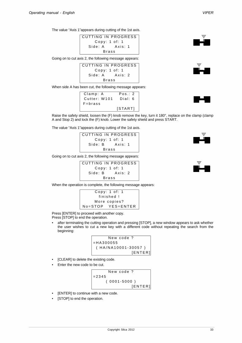
The value “Axis 1”appears during cutting of the 1st axis.
Going on to cut axis 2, the following message appears:
When side A has been cut, the following message appears:
Raise the safety shield, loosen the (F) knob remove the key, turn it 180°, replace on the clamp (clamp A and Stop 2) and lock the (F) knob. Lower the safety shield and press START.
The value “Axis 1”appears during cutting of the 1st axis.
Going on to cut axis 2, the following message appears:
When the operation is complete, the following message appears:
Press [ENTER] to proceed with another copy.Press [STOP] to end the operation.
• after terminating the cutting operation and pressing [STOP], a new window appears to ask whether the user wishes to cut a new key with a different code without repeating the search from the beginning:
• [CLEAR] to delete the existing code.
• Enter the new code to be cut.
• [ENTER] to continue with a new code.
• [STOP] to end the operation.
C U T T I N G I N P R O G R E S SC o p y : 1 o f : 1
S i d e : A A x i s : 1B r a s s
C U T T I N G I N P R O G R E S SC o p y : 1 o f : 1
S i d e : A A x i s : 2B r a s s
C l a m p : A P o s . : 2C u t t e r : W 1 0 1 D i a l : 6
F = b r a s s [ S TA R T ]
C U T T I N G I N P R O G R E S SC o p y : 1 o f : 1
S i d e : B A x i s : 1B r a s s
C U T T I N G I N P R O G R E S SC o p y : 1 o f : 1
S i d e : B A x i s : 2B r a s s
C o p y : 1 o f : 1f i n i s h e d !
M o r e c o p i e s ?N o = S T O P Y E S = E N T E R
N e w c o d e ? = H A 3 0 0 0 5 5
( H A / N A 1 0 0 0 1 - 3 0 0 5 7 )[ E N T E R ]
N e w c o d e ? = 2 3 4 5
( 0 0 0 1 - 5 0 0 0 )[ E N T E R ]
Copyright Silca 2012 33
Operating manual - English VIPER
5.6 USE OF THE MACHINE WITH A PERSONAL COMPUTERIn the previous pages the VIPER key-cutting machine operations and parts have been presented as a stand alone machine with the data stored in the machine memory.It is of interest to examine a very important function regarding connection to a PC so that the machine can receive data directly.The "Silca Keys Program" makes it possible to interface with the VIPER and transmit the cutting data required and selected, through the powerful program made available. It is also possible to store the selected keys in a special work queue (or file) so that they can be transmitted to the machine as soon as it is available.Each combination sent to the VIPER corresponds to a step in the cutting process for the number of keys entered on the PC.When the cutting operation is finished for the number of keys set, a ‘+’ sign shows the end of the cycle.When the VIPER is turned off in the middle of a work queue, the machine stores the status of the work done in its memory.When the machine is turned on again the unfinished cutting operations will be easily found with the number of keys still to be cut.
Note: the key combinations transmitted by the Personal Computer cannot be altered by the operator.
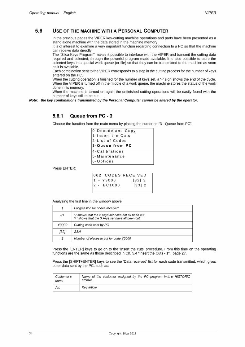
5.6.1 Queue from PC - 3Choose the function from the main menu by placing the cursor on “3 - Queue from PC”.
Press ENTER:
Analysing the first line in the window above:
Press the [ENTER] keys to go on to the ‘Insert the cuts’ procedure. From this time on the operating functions are the same as those described in Ch. 5.4 "Insert the Cuts - 1", page 27.
Press the [SHIFT+ENTER] keys to see the ‘Data received’ list for each code transmitted, which gives other data sent by the PC, such as:
0 - D e c o d e a n d C o p y1 - I n s e r t t h e C u t s2 - L i s t o f C o d e s3 - Q u e u e f r o m P C4 - C a l i b r a t i o n s 5 - M a i n t e n a n c e6 - O p t i o n s
0 0 2 C O D E S R E C E I V E D1 + Y 3 0 0 0 [ 3 2 ] 32 - B C 1 0 0 0 [ 3 3 ] 2
1 Progression for codes received
-/+ ‘-‘ shows that the 2 keys set have not all been cut ‘+’ shows that the 3 keys set have all been cut.
Y3000 Cutting code sent by PC
[32] SSN
3 Number of pieces to cut for code Y3000
Customer’s name
Name of the customer assigned by the PC program in th e HISTORIC archive
Art. Key article
34 Copyright Silca 2012
Operating manual - English VIPER
Each key received by the PC has a set quantity (or number of pieces). The machine program decreases the number with every key cut and stores the count in its memory even when the machine is turned off.For this purpose a [START] key has been added in order to search for the first code in the list with a number of cut keys lower than that set.
Operational keys• Arrow keys: to scroll the lines.
• SHIFT] + [arrows] to scroll 4 lines at a time.
• [SHIFT+ENTER] keys to view customer data and key article for the code selected.
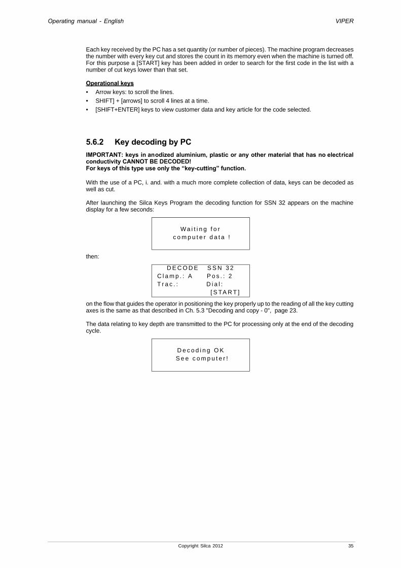
5.6.2 Key decoding by PCIMPORTANT: keys in anodized aluminium, plastic or any other material that has no electrical conductivity CANNOT BE DECODED!For keys of this type use only the “key-cutting” function.
With the use of a PC, i. and. with a much more complete collection of data, keys can be decoded as well as cut.
After launching the Silca Keys Program the decoding function for SSN 32 appears on the machine display for a few seconds:
then:
on the flow that guides the operator in positioning the key properly up to the reading of all the key cutting axes is the same as that described in Ch. 5.3 "Decoding and copy - 0", page 23.
The data relating to key depth are transmitted to the PC for processing only at the end of the decoding cycle.
Wa i t i n g f o r c o m p u t e r d a t a !
D E C O D E S S N 3 2 C l a m p . : A P o s . : 2 T r a c . : D i a l :
[ S TA R T ]
D e c o d i n g O K S e e c o m p u t e r !
Copyright Silca 2012 35
Operating manual - English VIPER
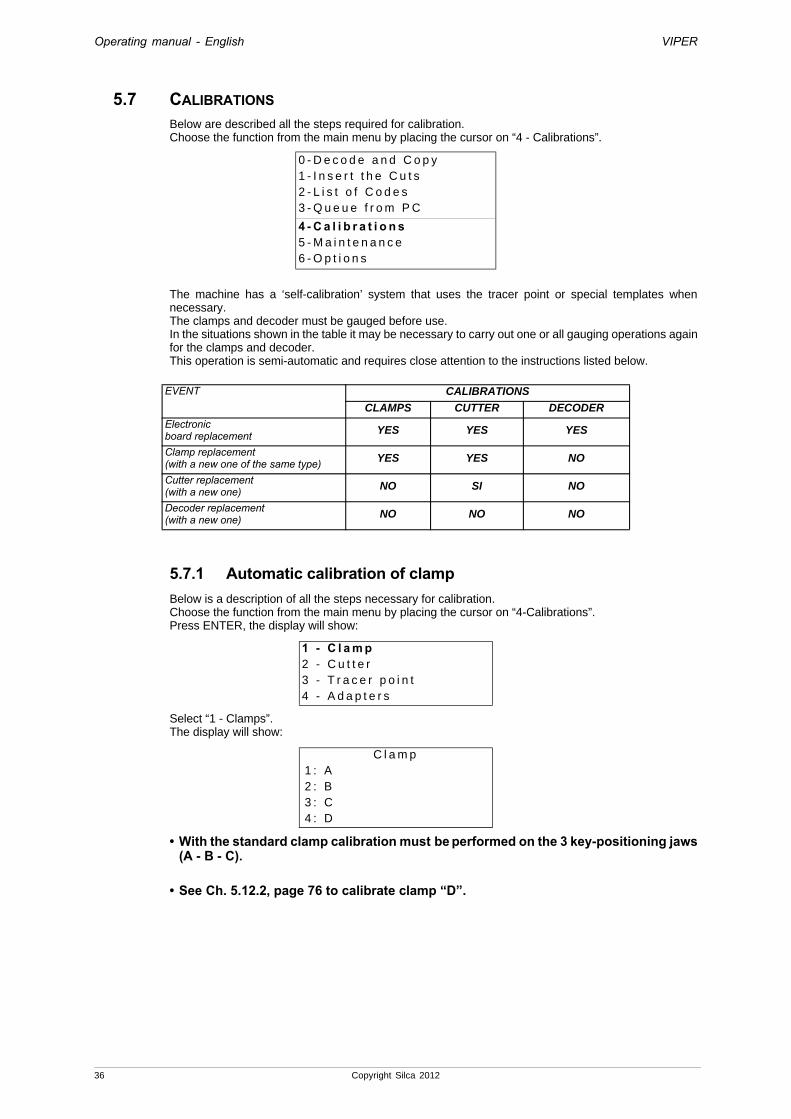
5.7 CALIBRATIONS Below are described all the steps required for calibration.Choose the function from the main menu by placing the cursor on “4 - Calibrations”.
The machine has a ‘self-calibration’ system that uses the tracer point or special templates when necessary.The clamps and decoder must be gauged before use.In the situations shown in the table it may be necessary to carry out one or all gauging operations again for the clamps and decoder.This operation is semi-automatic and requires close attention to the instructions listed below.
5.7.1 Automatic calibration of clampBelow is a description of all the steps necessary for calibration.Choose the function from the main menu by placing the cursor on “4-Calibrations”.Press ENTER, the display will show:
Select “1 - Clamps”.The display will show:
• With the standard clamp calibration must be performed on the 3 key-positioning jaws (A - B - C).
• See Ch. 5.12.2, page 76 to calibrate clamp “D”.
0 - D e c o d e a n d C o p y1 - I n s e r t t h e C u t s2 - L i s t o f C o d e s3 - Q u e u e f r o m P C
4 - C a l i b r a t i o n s 5 - M a i n t e n a n c e6 - O p t i o n s
EVENT CALIBRATIONS
CLAMPS CUTTER DECODER
Electronicboard replacement YES YES YES
Clamp replacement(with a new one of the same type) YES YES NO
Cutter replacement(with a new one) NO SI NO
Decoder replacement(with a new one) NO NO NO
1 - C l a m p2 - C u t t e r3 - T r a c e r p o i n t4 - A d a p t e r s
C l a m p 1 : A 2 : B 3 : C 4 : D
36 Copyright Silca 2012

Operating manual - English VIPER
• CLAMP APlace the pointer on “1”, press ENTER, and the display will show the message:
The X and Y values can be different from “00” due to previous calibration.Before calibration, check that there are no keys on the clamp.Press START; the display will show the message:
- Loosen the (F1) handle by one turn and pull the (F2) anatomic grip towards the operator. This releases the clamp, which must be slid to the right. Release the anatomic grip, move the clamp manually and the positioning device will lock the clamp in the clamp reference notch. When the clamp is in position (Clamp A) tighten the (F1) handle.
- Turn the (F) knob to the left.
- Fit the Z22 template into jaw A (fig. 30) so that it lies flat against the clamp with the area marked A up against Stop 2 (to do this, turn the Stop1 plate to the left and downwards).
- Secure the Z22 template by turning the (F) knob to the right.
Fig. 30press ENTER; the display will show the message:
Attention: calibration of the CLAMPS (A-B-C) MUST BE CARRIED OUT with the TRACER POINT U111 fitted in the place of the cutter.
Attention: loosen the lever (N) and turn the (O) dial to position 10.Remove the W101 cutter and fit the U111 tracer point, making sure the tracer point is not damaged, bent or split (Ch. 4.6 "Changing the cutter and/or the tracer point", page 19).- close the protective shield. Press START.
- start automatic calibration of the clamp by electrical contact.
- the display will show:
At the end of the operation the following message will appear (e.g.):
C l a m p : A A d j u s t m e n t :
X = + 0 0 Y = + 0 0To c a l i b r a t e [ S TA R T ]
C l a m p : AT e m p l . : Z 2 2 - A P o s . : 2S e e o p e r a t i n g m a n u a l
[ E N T E R ]
C l a m p : A D i a l : 1 0 T r a c e r : U 1 1 1
S e e o p e r a t i n g m a n u a l[ S TA R T ]
C l a m p : AD e t e c t i o n
i n p r o g r e s s !
F2
Z22
Z22F
F1
Copyright Silca 2012 37
Operating manual - English VIPER
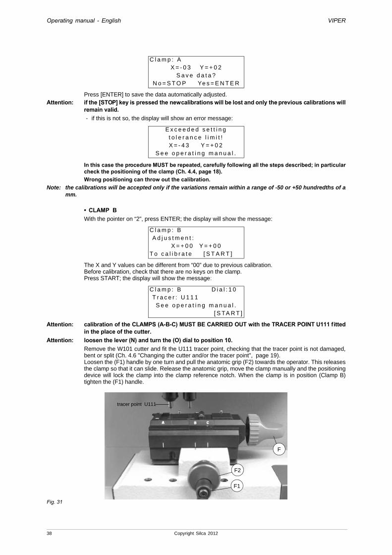
Press [ENTER] to save the data automatically adjusted.Attention: if the [STOP] key is pressed the new calibrations will be lost and only the previous calibrations will
remain valid.- if this is not so, the display will show an error message:
In this case the procedure MUST be repeated, carefully following all the steps described; in particular check the positioning of the clamp (Ch. 4.4, page 18).Wrong positioning can throw out the calibration.
Note: the calibrations will be accepted only if the variations remain within a range of -50 or +50 hundredths of a mm.
• CLAMP BWith the pointer on “2”, press ENTER; the display will show the message:
The X and Y values can be different from “00” due to previous calibration.Before calibration, check that there are no keys on the clamp.Press START; the display will show the message:
Attention: calibration of the CLAMPS (A-B-C) MUST BE CARRIED OUT with the TRACER POINT U111 fitted in the place of the cutter.
Attention: loosen the lever (N) and turn the (O) dial to position 10.Remove the W101 cutter and fit the U111 tracer point, checking that the tracer point is not damaged, bent or split (Ch. 4.6 "Changing the cutter and/or the tracer point", page 19).Loosen the (F1) handle by one turn and pull the anatomic grip (F2) towards the operator. This releases the clamp so that it can slide. Release the anatomic grip, move the clamp manually and the positioning device will lock the clamp into the clamp reference notch. When the clamp is in position (Clamp B) tighten the (F1) handle.
Fig. 31
C l a m p : AX = - 0 3 Y = + 0 2
S a v e d a t a ?N o = S T O P Ye s = E N T E R
E x c e e d e d s e t t i n gt o l e r a n c e l i m i t !X = - 4 3 Y = + 0 2
S e e o p e r a t i n g m a n u a l .
C l a m p : B A d j u s t m e n t :
X = + 0 0 Y = + 0 0T o c a l i b r a t e [ S T A R T ]
C l a m p : B D i a l : 1 0 T r a c e r : U 1 1 1
S e e o p e r a t i n g m a n u a l . [ S TA R T ]
tracer point U111
F2
F1
F
38 Copyright Silca 2012
Operating manual - English VIPER
- close the protective shield. Press START,
- start automatic calibration of the clamp by electrical contact.
the display will show:
At the end of the operation the following message will appear (e.g.):
Press [ENTER] to save the data automatically adjusted.Attention: if the [STOP] key is pressed the new calibrations will be lost and only the previous calibrations will
remain valid.- if this is not so, the display will show an error message:
In this case the procedure MUST be repeated, carefully following all the steps described; in particular check the positioning of the clamp (Ch. 4.4, page 18).Wrong positioning can throw out the calibration.
Note: the calibrations will be accepted only if the variations remain within a range of -50 or +50 hundredths of a mm.
• CLAMP CWith the pointer on “2”, press ENTER; the display will show the message:
The X and Y values can be different from “00” due to previous calibration.Before calibration, check that there are no keys on the clamp.Press START, the display will show:
Attention: calibration of the CLAMPS (A-B-C) MUST BE CARRIED OUT with the TRACER POINT U111 fitted in the place of the cutter.
Attention: loosen the lever (N) and turn the (O) dial to position 10.Remove the W101 cutter and fit the U111 tracer point/decoder, checking that the tracer point is not damaged, bent or split (Ch. 4.6 "Changing the cutter and/or the tracer point", page 19).Loosen the (F1) handle (fig. 32) by one turn and pull the anatomic grip (F2) towards the operator. This releases the clamp so that it can slide. Release the anatomic grip, move the clamp manually and the positioning device will lock the clamp into the clamp reference notch. When the clamp is in position (Clamp C) tighten the (F1) handle.
C l a m p : BD e t e c t i o n
i n p r o g r e s s !
C l a m p : BX = - 0 2 Y = + 0 1S a v e d a t a ?
N o = S T O P Ye s = E N T E R
E x c e e d e d s e t t i n gt o l e r a n c e l i m i t !X = - 0 2 Y = + 4 2
S e e o p e r a t i n g m a n u a l .
C l a m p : C A d j u s t m e n t :
X = + 0 0 Y = + 0 0T o c a l i b r a t e [ S T A R T ]
C l a m p : C D i a l : 1 0 T r a c e r : U 1 1 1
S e e o p e r a t i n g m a n u a l . [ S TA R T ]
Copyright Silca 2012 39

Operating manual - English VIPER
Fig. 32- close the protective shield. Press START.
- start automatic calibration of the clamp by electrical contact.
the display will show:
At the end of the operation the following message will appear (e.g.):
Press [ENTER] to save the data automatically adjusted.Attention: if the [STOP] key is pressed the new calibrations will be lost and only the previous calibrations will
remain valid.- if this is not so, the display will show an error message:
In this case the procedure MUST be repeated, carefully following all the steps described; in particular check the positioning of the clamp (Ch. 4.4, page 18).Wrong positioning can throw out the calibration.
Note: the calibrations will be accepted only if the variations remain within a range of -50 or +50 hundredths of a mm.
C l a m p : CD e t e c t i o n
i n p r o g r e s s !
C l a m p : CX = + 0 4 Y = + 0 1
S a v e d a t a ?N o = S T O P Ye s = E N T E R
E x c e e d e d s e t t i n gt o l e r a n c e l i m i t !X = + 4 4 Y = + 0 1
S e e o p e r a t i n g m a n u a l .
tracer point U111
F2
F1
F
40 Copyright Silca 2012

Operating manual - English VIPER
5.7.2 Cutter calibration Note: the VIPER key-cutting machine is already gauged when delivered. In the event of replacing the cutter or
checking cutting depth gauging, proceed as follows:First check that clamp, cutter and Z22 template are all perfectly clean.Choose the function from the main menu by placing the cursor on “4 - Calibrations”.Press ENTER, the display shows:
Select “2 - Cutters”.the display will show:
Check that the W101 (Standard) cutter is installed. If not, see ch. 4.6 "Changing the cutter and/or the tracer point".Press ENTER, the display shows:
Press ENTER, the display will show:
Fig. 33
- Raise the safety shield, loosen the (F1) handle by one turn and pull the anatomic grip (F2) towards the operator. This releases the clamp so that it can slide to the right. Release the anatomic grip, move the clamp manually and the positioning device will lock the clamp into the clamp reference notch. When the clamp is in position (Clamp A) tighten the (F1) handle.
- Turn the (F) knob to the left.
- Fit the Z22 template into jaw A so that it lies flat on the clamp with the area marked B up against Stop 2 (to do this, turn the Stop 1 plate to the left and downwards).
- Secure the Z22 template by turning the (F) knob to the right.
1 - C l a m p2 - C u t t e r s3 - T r a c e r p o i n t4 - A d a p t o r s
C u t t e r 1 : W 1 0 1 2 : W 1 1 4 3 : H 1 5 8 4 : W 3 0 2
C a l i b r a t e h e i g h tc u t t e r W 1 0 1
[ E N T E R ]
C l a m p : AT e m p l . : Z 2 2 - B P o s . : 2
S e e o p e r a t i n g m a n u a l .[ E N T E R ]
F2
F1
F
Copyright Silca 2012 41
Operating manual - English VIPER
Press ENTER; the display will show the message:
Release the lever (N) turn it and place it against the vertical side of the machine. Press ENTER; the display will show:
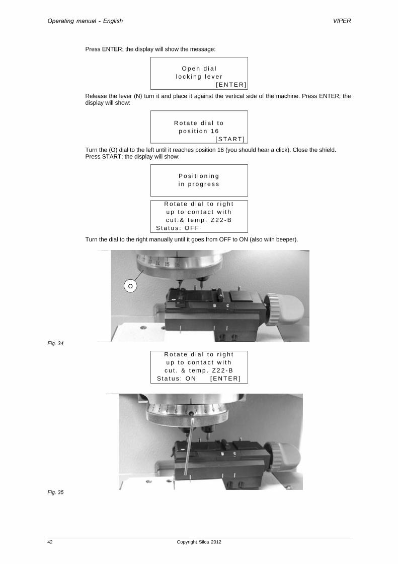
Turn the (O) dial to the left until it reaches position 16 (you should hear a click). Close the shield.Press START; the display will show:
Turn the dial to the right manually until it goes from OFF to ON (also with beeper).
Fig. 34
Fig. 35
O p e n d i a ll o c k i n g l e v e r
[ E N T E R ]
R o t a t e d i a l t op o s i t i o n 1 6
[ S TA R T ]
P o s i t i o n i n gi n p r o g r e s s
R o t a t e d i a l t o r i g h tu p t o c o n t a c t w i t h c u t . & t e m p . Z 2 2 - B
S t a t u s : O F F
R o t a t e d i a l t o r i g h tu p t o c o n t a c t w i t h
c u t . & t e m p . Z 2 2 - BSt a t u s : O N [ E N T E R ]
O
42 Copyright Silca 2012
Operating manual - English VIPER
As soon as it goes to ON, press ENTER, and the display will show:
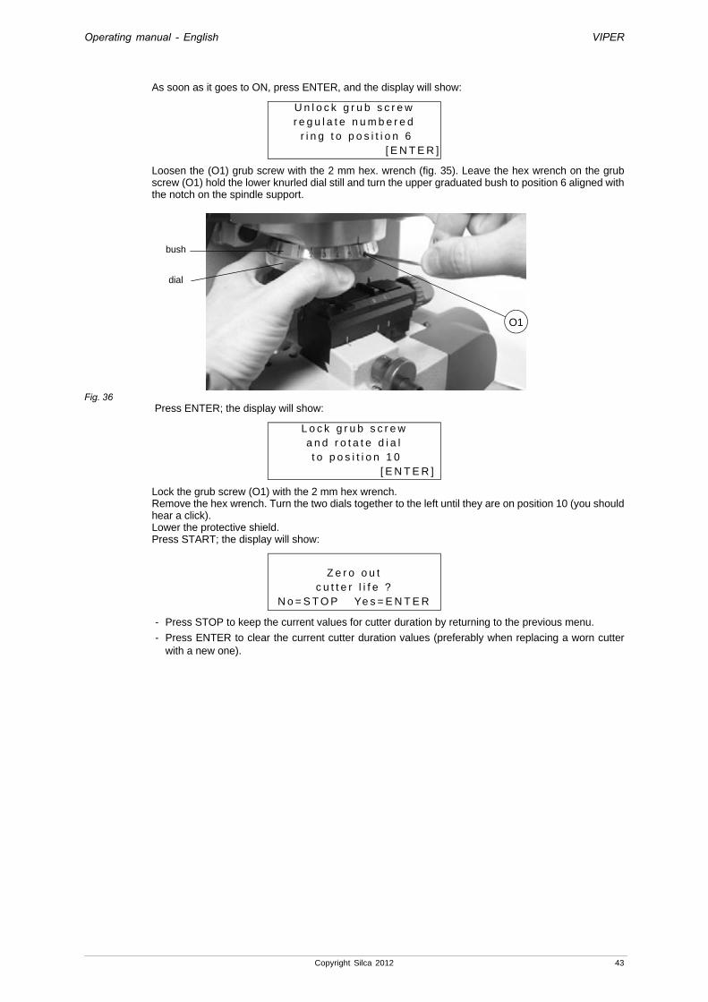
Loosen the (O1) grub screw with the 2 mm hex. wrench (fig. 35). Leave the hex wrench on the grub screw (O1) hold the lower knurled dial still and turn the upper graduated bush to position 6 aligned with the notch on the spindle support.
Fig. 36 Press ENTER; the display will show:
Lock the grub screw (O1) with the 2 mm hex wrench.Remove the hex wrench. Turn the two dials together to the left until they are on position 10 (you should hear a click).Lower the protective shield.Press START; the display will show:
- Press STOP to keep the current values for cutter duration by returning to the previous menu.
- Press ENTER to clear the current cutter duration values (preferably when replacing a worn cutter with a new one).
U n l o c k g r u b s c r e wr e g u l a t e n u m b e r e d r i n g t o p o s i t i o n 6
[ E N T E R ]
L o c k g r u b s c r e wa n d r o t a t e d i a l t o p o s i t i o n 1 0
[ E N T E R ]
Z e r o o u tc u t t e r l i f e ?
N o = S T O P Ye s = E N T E R
O1
bush
dial
Copyright Silca 2012 43

Operating manual - English VIPER
5.7.3 Decoder calibration Note: the VIPER key-cutting machine is already gauged when delivered. In the event of replacing the decoder (Ch.
7.12) or checking cutting depth gauging, proceed as follows:First check that clamp, decoder and Z22 template are all perfectly clean.Choose the function from the main menu by placing the cursor on “Calibrations”.Press ENTER, the display will show:
Select “3 - Decoder”. The display will show:
Check that the U111DC decoder on the machine is in good condition. If not, see ch. 7.12 "Decoder (U111DC) replacement".
Press START, the display will show:
Fig. 37
- Loosen the (F1) handle by one turn and pull the anatomic grip (F2) towards the operator. This releases the clamp so that it can slide to the right.
- Release the anatomic grip, move the clamp manually and the positioning device will lock the clamp into the clamp reference notch. When the clamp is in position (Clamp A) tighten the (F1) handle.
- Turn the (F) knob. to the left. Fit the Z22 template into jaw A so that it lies flat on the clamp with the area marked A up against Stop 2 (to do this, turn the Stop 1 plate to the left and downwards).Secure the Z22 template by turning the (F) knob to the right.
- Press ENTER; the display will show the message:
1 - C l a m p2 - C u t t e r3 - T r a c e r p o i n t4 - A d a p t o r s
T R A C E R A d j u s t m e n t : U 1 1 1 D C : X = - 0 2 Y = - 1 8 T o c a l i b r a t e [ S T A R T ]
C l a m p : AT e m p l . : Z 2 2 - A P o s . : 2
S e e o p e r a t i n g m a n u a l .[ S TA R T ]
D e t e c t i o ni n p r o g r e s s !
U111DC
F2
Z22
Z22F
F1
44 Copyright Silca 2012
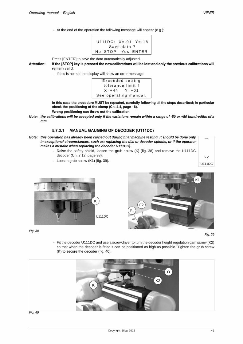
Operating manual - English VIPER
- At the end of the operation the following message will appear (e.g.):
Press [ENTER] to save the data automatically adjusted.Attention: if the [STOP] key is pressed the new calibrations will be lost and only the previous calibrations will
remain valid.- if this is not so, the display will show an error message:
In this case the procedure MUST be repeated, carefully following all the steps described; in particular check the positioning of the clamp (Ch. 4.4, page 18).Wrong positioning can throw out the calibration.
Note: the calibrations will be accepted only if the variations remain within a range of -50 or +50 hundredths of a mm.
5.7.3.1 MANUAL GAUGING OF DECODER (U111DC)Note: this operation has already been carried out during final machine testing. It should be done only
in exceptional circumstances, such as: replacing the dial or decoder spindle, or if the operator makes a mistake when replacing the decoder U111DC).
- Raise the safety shield, loosen the grub screw (K) (fig. 38) and remove the U111DC decoder (Ch. 7.12, page 98).
- Loosen grub screw (K1) (fig. 39).
Fig. 38Fig. 39
- Fit the decoder U111DC and use a screwdriver to turn the decoder height regulation cam screw (K2) so that when the decoder is fitted it can be positioned as high as possible. Tighten the grub screw (K) to secure the decoder (fig. 40).
Fig. 40
U 111 D C : X = - 0 1 Y = - 1 8 S a v e d a t a ?
N o = S T O P Ye s = E N T E R
E x c e e d e d s e t t i n gt o l e r a n c e l i m i t !X = + 4 4 Y = + 0 1
S e e o p e r a t i n g m a n u a l .
U111DC
K
K1
F2
F1
U111DC
K2
O
K
Copyright Silca 2012 45

Operating manual - English VIPER
- Loosen the lever (N) and turn the (O) dial to the left until it reaches position 10 (you should hear it click into place)
- Loosen the (F1) handle by one turn and pull the anatomic grip (F2) towards the operator. This releases the clamp so that it can slide to the right. Release the anatomic grip and move the clamp manually. The positioning device will lock the clamp in the clamp reference notch.
- When the clamp is in position (Clamp A) tighten the (F1) handle.
- Turn the (F) knob to the left. Fit the Z22-B template into jaw A so that it lies flat on the clamp and is well up against Stop 2 (to do this the Stop 1 plate must be turned left and downwards).
- Secure the Z22 template by turning the (F) knob to the right.
- Move the carriages manually, taking the area marked C on the Z22 template precisely under the U111DC decoder.
- Turn the (O) dial to the right until it reaches position 6 (you should hear it click into place).
Fig. 41
- Start the key-cutting machine, enter the main menu and position the pointer on “4 - Maintenance”.
Press ENTER; the display will show the message:
- position the pointer on “2 - Test” and press ENTER; the display will show:
- position the pointer on “7 – Electric Contact” and press ENTER; the display will show:
1 - C u t t e r2 - T e s t3 - C u t t i n g T e s t4 - H e a t i n g c u t t e r
1 - X a x i s m o t o r2 - Y a x i s m o t o r3 - C u t t e r m o t o r4 - X a x i s s e n s o r > >5 - Y a x i s s e n s o r6 - S h i e l d m i c r o7 - E l e c t r i c c o n t a c t8 - D i a l l o c k l e v e r9 - K e y b o a r d1 0 - D i s p l a y1 1 - S e r i a l p o r t1 2 - B a t t e r y s t a t u s
7 E L E C T R I C C O N TA C TM a k e a c o n t a c t
C U T T E R T R A C E RSt a t . : O F F S t a t . : O F F
F1
F2F
N
O
46 Copyright Silca 2012
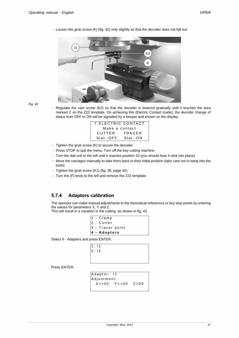
Operating manual - English VIPER
- Loosen the grub screw (K) (fig. 42) only slightly so that the decoder does not fall out.
Fig. 42- Regulate the cam screw (K2) so that the decoder is lowered gradually until it touches the area
marked C on the Z22 template. On achieving this (Electric Contact made), the decoder change of status from OFF to ON will be signalled by a beeper and shown on the display:
- Tighten the grub screw (K) to secure the decoder.
- Press STOP to quit the menu. Turn off the key-cutting machine.
- Turn the dial unit to the left until it reaches position 10 (you should hear it click into place)
- Move the carriages manually to take them back to their initial position (take care not to bang into the tools).
- Tighten the grub screw (K1) (fig. 39, page 45).
- Turn the (F) knob to the left and remove the Z22 template.
5.7.4 Adaptors calibration The operator can make manual adjustments to the theoretical references or key stop points by entering the values for parameters X, Y and Z.This will result in a variation in the cutting, as shown in fig. 43.
Select 4 - Adapters and press ENTER.
Press ENTER.
7 E L E C T R I C C O N TA C TM a k e a c o n t a c t
C U T T E R T R A C E RSt a t . : O F F S t a t . : O N
1 - C l a m p2 - C u t t e r3 - T r a c e r p o i n t4 - A d a p t o r s
1 : I 12 : I 2
A d a p t o r : I 1A d j u s t m e n t :
X = + 0 2 Y = + 0 4 Z = 0 0
K
O
K2
Copyright Silca 2012 47

Operating manual - English VIPER
Use the arrows or [ENTER] to place the cursor at the side of the parameter to alter and change the parameters with the following keys:
• SHIFT + [up arrow] increases the value within +50 hundredths of a mm
• SHIFT + [down arrow] decreases the value within - 50 hundredths of a mm
• CLEAR to zero the value
• [ENTER] in the last field allows you to quit the window and save the alterations made:Attention: if you press [STOP] the new values will not be saved and the previous calibration settings will
remain valid.
Figura 43
S a v e a d j u s t m e n t ?
N o = S T O P Ye s = E N T E R
-X +X
-Y
+Y
48 Copyright Silca 2012
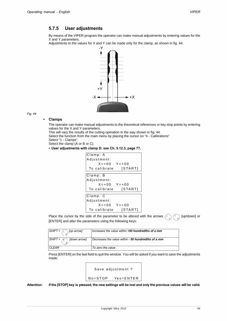
Operating manual - English VIPER
5.7.5 User adjustmentsBy means of the VIPER program the operator can make manual adjustments by entering values for the X and Y parameters.Adjustments to the values for X and Y can be made only for the clamp, as shown in fig. 44.
Fig. 44
• ClampsThe operator can make manual adjustments to the theoretical references or key stop points by entering values for the X and Y parameters.This will vary the results of the cutting operation in the way shown in fig. 44.Select the function from the main menu by placing the cursor on “4 - Calibrations”Select “1 - Clamps”.Select the clamp (A or B or C).• User adjustments with clamp D: see Ch. 5.12.3, page 77.
Place the cursor by the side of the parameter to be altered with the arrows [up/down] or
[ENTER] and alter the parameters using the following keys:
Press [ENTER] on the last field to quit the window. You will be asked if you want to save the adjustments made:
Attention: if the [STOP] key is pressed, the new settings will be lost and only the previous values will be valid.
C l a m p : AA d j u s t m e n t :
X = + 0 0 Y = + 0 0To c a l i b r a t e [ S TA R T ]
C l a m p : BA d j u s t m e n t :
X = + 0 0 Y = + 0 0To c a l i b r a t e [ S TA R T ]
C l a m p : CA d j u s t m e n t :
X = + 0 0 Y = + 0 0To c a l i b r a t e [ S TA R T ]
SHIFT + [up arrow] Increases the value within +50 hundredths of a mm
SHIFT + [down arrow] Decreases the value within - 50 hundredths of a mm
CLEAR To zero the value
S a v e a d j u s t m e n t ?
N o = S T O P Ye s = E N T E R
-Y
+Y
-X +X
Copyright Silca 2012 49

Operating manual - English VIPER
5.8 MAINTENANCE - 4All the steps necessary for maintenance are described below.
5.8.1 CuttersSelect the function from the main menu by placing the cursor on “4 - Maintenance.Press ENTER, the display will show:
The menu item "CUTTERS" includes the tool used by VIPER with its characteristics.Use the [ENTER] key to go to the item "1 - Cutters" or press the "1" key to view the tool used by the machine.
Fig. 45Press ENTER, the display will show:
Move with the arrow keys or [ENTER] onto the field to be altered and press [SHIFT]+ [down arrow
key] to alter the value from those admissible:
Attention: use cutters provided by SILCA.
* DURATION:LOWSTANDARDHIGHCUSTOM 3X = STANDARD x 3CUSTOM 4X = STANDARD x 4
1 - C u t t e r2 - T e s t3 - C u t t i n g T e s t4 - H e a t i n g c u t t e r
C u t t e r 1 : W 1 0 1 2 : W 1 1 4 3 : H 1 5 8 4 : W 3 0 2
C u t t e r : 1 0 1 M a t . = WL i f e = [ X X X X X X X X X X ] %D u r a t i o n = S T A N D A R DL e n g . : 4 0 0 0 B a s e : 2 5 0
Material The user can select H = HSS or W = Hard Metal, according to the material of the cutter to be used. Cutter W101 = Standard
Life Shows the life of a (new) cutter with 10 black squares. The fewer the black squares the more worn the cutter is (this characteristic of the cutter cannot be modified, variable by the selected duration)
*Duration Select: LOW / STANDARD / HIGH / CUSTOM 3X / CUSTOM 4XA STANDARD value is normally established
Length Cutter length 40 (unalterable characteristic of the cutter)B. Cutting The cutter cutting base (unalterable characteristic of the cutter)
50 Copyright Silca 2012

Operating manual - English VIPER
5.8.2 TESTThere is a TEST menu on the machine, for use in the event of faulty operation or for checks.
Attention: this ‘Test’ chapter can be used to check any errors/anomalies that could occur on the machine (Ch. 7.1 "Trouble shooting", page 87).Select the function from the main menu by placing the cursor on “4 - Maintenance”Select “2 - Test”.
Operational keys: arrow keys [Up/Down] to position the cursor on the option required, and press [Enter].
• Test 1: X AXIS MOTOR (top carriage)
Carefully follow the instructions on the display and check that the X axis carriage moves.- With the arrow [Down] the carriage moves to the right.
- With arrow [Up] the carriage moves to the left.
Attention: during this test all the end of run controls are disabled; avoid moving the carriage up against its mechanical stops.
Note: if the motor does not start, contact Silca’s Technical Assistance Dept.
• Test 2: Y AXIS MOTOR (bottom carriage)
Carefully follow the instructions on the display and check that the Y axis carriage moves.- With the arrow [Down] the carriage moves towards the operator.
- With the arrow [Up] the carriage moves towards the cutter.
Attention: during this test all the end of run controls are disabled; avoid moving the carriage up against its mechanical stops.
Note: if the motor does not start, contact Silca’s Technical Assistance Dept.
• Test 3: CUTTER MOTOR
Carefully follow the instructions on the display and check that the cutter motor works.Note: if the cutter motor does not turn, contact Silca’s Technical Assistance Dept.
1 - X a x i s m o t o r2 - Y a x i s m o t o r3 - C u t t e r m o t o r4 - X a x i s s e n s o r > >5 - Y a x i s s e n s o r6 - S h i e l d m i c r o7 - E l e c t r i c c o n t a c t8 - D i a l l o c k l e v e r9 - K e y b o a r d1 0 - D i s p l a y1 1 - S e r i a l p o r t1 2 - B a t t e r y s t a t u s
1 X A X I S M O T O RP r e s s a r r o w e d k e y s
t o m o v e a x i s .
2 Y A X I S M O T O RP r e s s a r r o w e d k e y s
t o m o v e a x i s .
3 C U T T E R M O T O RS TA R T k e y t o
a c t i v a t e m o t o r .
Copyright Silca 2012 51
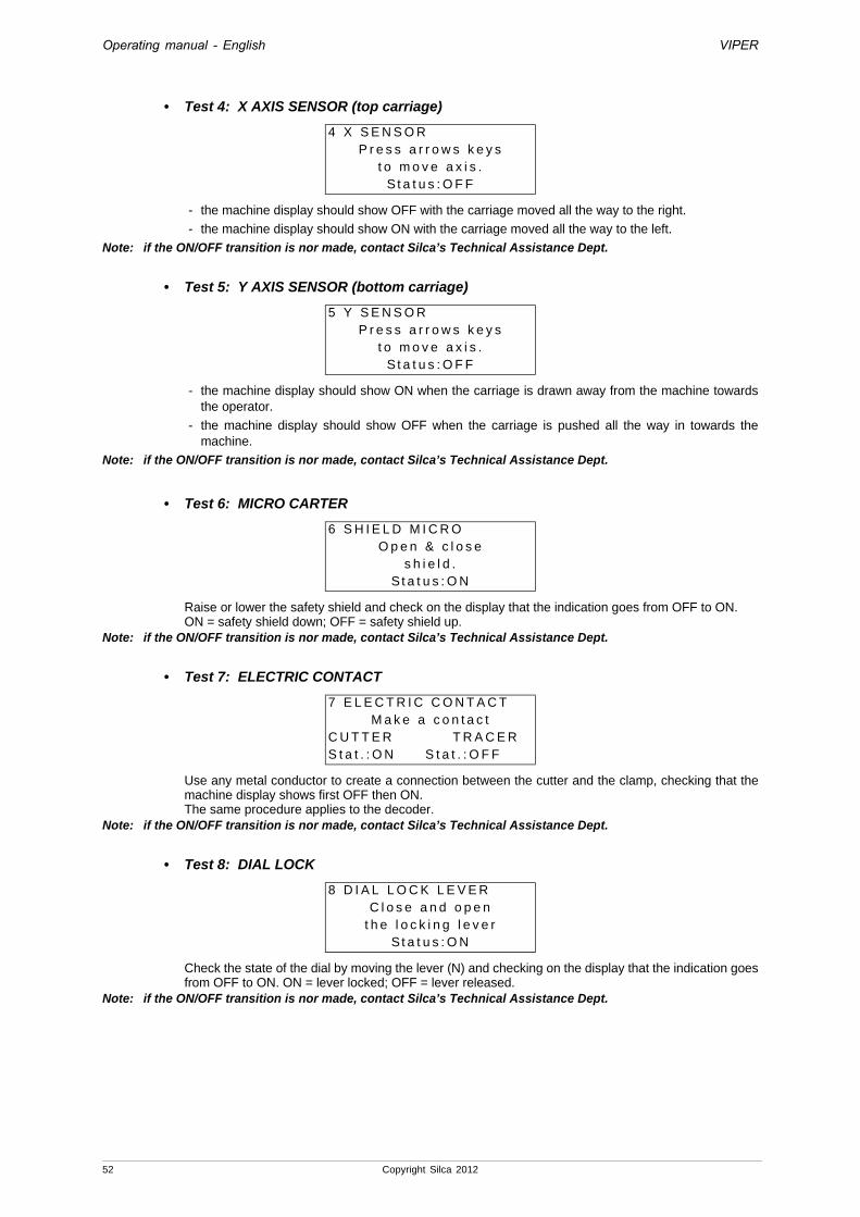
Operating manual - English VIPER
• Test 4: X AXIS SENSOR (top carriage)
- the machine display should show OFF with the carriage moved all the way to the right.
- the machine display should show ON with the carriage moved all the way to the left.
Note: if the ON/OFF transition is nor made, contact Silca’s Technical Assistance Dept.
• Test 5: Y AXIS SENSOR (bottom carriage)
- the machine display should show ON when the carriage is drawn away from the machine towards the operator.
- the machine display should show OFF when the carriage is pushed all the way in towards the machine.
Note: if the ON/OFF transition is nor made, contact Silca’s Technical Assistance Dept.
• Test 6: MICRO CARTER
Raise or lower the safety shield and check on the display that the indication goes from OFF to ON.ON = safety shield down; OFF = safety shield up.
Note: if the ON/OFF transition is nor made, contact Silca’s Technical Assistance Dept.
• Test 7: ELECTRIC CONTACT
Use any metal conductor to create a connection between the cutter and the clamp, checking that the machine display shows first OFF then ON.The same procedure applies to the decoder.
Note: if the ON/OFF transition is nor made, contact Silca’s Technical Assistance Dept.
• Test 8: DIAL LOCK
Check the state of the dial by moving the lever (N) and checking on the display that the indication goes from OFF to ON. ON = lever locked; OFF = lever released.
Note: if the ON/OFF transition is nor made, contact Silca’s Technical Assistance Dept.
4 X S E N S O RP r e s s a r r o w s k e y s
t o m o v e a x i s .S t a t u s : O F F
5 Y S E N S O RP r e s s a r r o w s k e y s
t o m o v e a x i s .S t a t u s : O F F
6 S H I E L D M I C R OO p e n & c l o s e
s h i e l d .S t a t u s : O N
7 E L E C T R I C C O N T A C TM a k e a c o n t a c t
C U T T E R T R A C E RS t a t . : O N S t a t . : O F F
8 D I A L L O C K L E V E RC l o s e a n d o p e n
t h e l o c k i n g l e v e rS t a t u s : O N
52 Copyright Silca 2012

Operating manual - English VIPER
• Test 9: KEYPAD
Press all the keys (except STOP) one at a time and check that an asterisk (*) appears for each key pressed. Press STOP to quit.
Note: if this is not so, contact Silca’s Technical Assistance Dept.
• Test 10: DISPLAY
Press START and check that all points on the display should be obscured.Note: if this is not so, contact Silca’s Technical Assistance Dept.
• Test 11: SERIAL PORT
Check that the machine display shows OFF.Fit the special serial test connector (Z4) provided to the machine serial port, checking that the display shows first OFF then ON.
Note: if the ON/OFF transition is nor made, contact Silca’s Technical Assistance Dept.
• Test 12: BATTERY STATE
Check that the display shows <Charged>.If not, replace it (Ch. 7.16, page 100).
Note: the machine also works with a flat battery (the battery is used only for the function: Options > Set Clock).
9 K E Y B O A R D 0 0 0 0 0P r e s s 0 0 0 0 0k e y s 0 0 0 0 0
0 0 0 0 0 0 0 0 0 0
1 0 D I S P L A Y
S TA R T t o a c t i v a t e .
1 1 S E R I A L P O R TI n s t a l l s p e c i a lZ 4 c o n n e c t o r .
S t a t u s : O F F
1 2 B A T T E R Y S T A T U S
< C H A R G E D >
Copyright Silca 2012 53

Operating manual - English VIPER
5.8.3 Cutting Test
Enter the main menu and choose this function by placing the pointer on “4 - Maintenance”Select “3 - Cutting Test”.
Insert a key (HON66) or with the following dimensions:
Place the key in the clamp, as illustrated in fig. 46.
Fig. 46Fig. 47
Press START.
At the end of the operation remove the key/template (fig. 47) and check the dimensions with a centesimal gauge.
If the dimensions do not correspond, re-gauge (Ch. 5.7, page 36).
1 - C u t t e r s2 - T e s t3 - C u t t i n g T e s t4 - H e a t i n g c u t t e r
C l a m p : AC u t t . : W 1 0 1 D i a l : 5P o s . : 2
[ S TA R T ]
C u t t i n gi n p r o g r e s s !
2,2mm
6,2mm
1,95mm +/-0,05
6 mm +/-0,05
15 mm +/-0,05
54 Copyright Silca 2012

Operating manual - English VIPER
5.8.4 Heating cutterThis operation is performed to heat the cutter and ring nut unit so that the ring nut will rotate freely even when the machine has not been used for some time and/or is installed in a very cold place.
Select 4 – Cutter heating and press ENTER; the display will show:
Press START, the cutter motor will start and the display will show:
The time to complete the operation (120 seconds) is shown and decreases progressively as the seconds go by. Press STOP to interrupt the procedure.
At the end of the procedure (after 120 seconds) the display will show:
Press STOP to exit, or START to carry out a new cutter motor heating cycle.
5.8.5 Machine Zero PointsNote: this function is deliberately semi-concealed so that the operator cannot access this menu by mistake and
1 - C u t t e r s2 - T e s t3 - C u t t i n g T e s t4 - H e a t i n g c u t t e r
H e a t i n g p r o c e d u r eo f c u t t e r
m o t o r[ S TA R T ] t o a c t i v a t e
P r o c e d . i n p r o g r e s s1 2 0
[ S T O P ] i n t e r r u p t
P r o c e d . i n p r o g r e s s6 8
[ S T O P ] i n t e r r u p t
H e a t i n g p r o c e d u r eo f c u t t e r
m o t o r[ S TA R T ] t o a c t i v a t e
Copyright Silca 2012 55
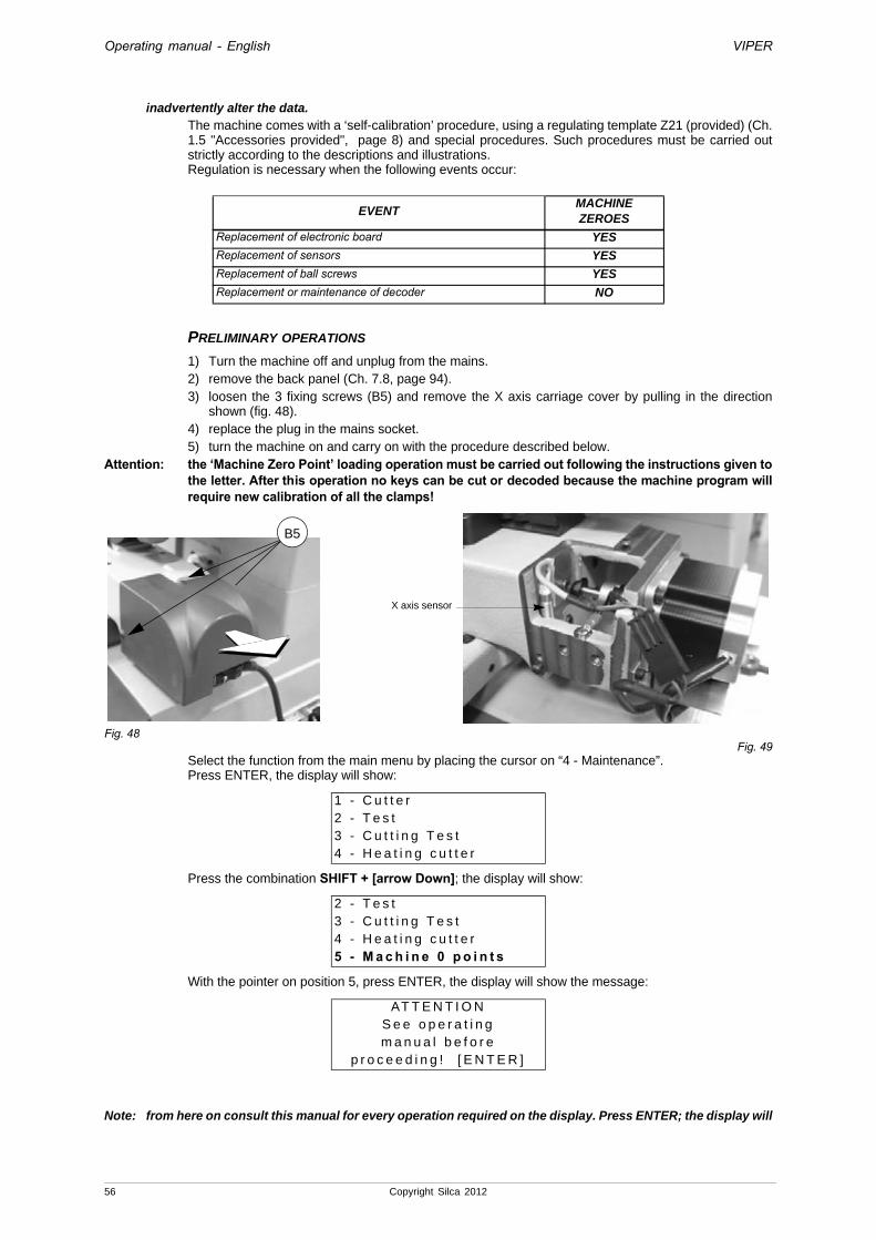
Operating manual - English VIPER
inadvertently alter the data. The machine comes with a ‘self-calibration’ procedure, using a regulating template Z21 (provided) (Ch. 1.5 "Accessories provided", page 8) and special procedures. Such procedures must be carried out strictly according to the descriptions and illustrations.Regulation is necessary when the following events occur:
PRELIMINARY OPERATIONS
1) Turn the machine off and unplug from the mains.2) remove the back panel (Ch. 7.8, page 94).3) loosen the 3 fixing screws (B5) and remove the X axis carriage cover by pulling in the direction
shown (fig. 48).4) replace the plug in the mains socket.5) turn the machine on and carry on with the procedure described below.
Attention: the ‘Machine Zero Point’ loading operation must be carried out following the instructions given to the letter. After this operation no keys can be cut or decoded because the machine program will require new calibration of all the clamps!
Fig. 48Fig. 49
Select the function from the main menu by placing the cursor on “4 - Maintenance”.Press ENTER, the display will show:
Press the combination SHIFT + [arrow Down]; the display will show:
With the pointer on position 5, press ENTER, the display will show the message:
Note: from here on consult this manual for every operation required on the display. Press ENTER; the display will
EVENTMACHINEZEROES
Replacement of electronic board YES
Replacement of sensors YES
Replacement of ball screws YES
Replacement or maintenance of decoder NO
1 - C u t t e r2 - T e s t3 - C u t t i n g T e s t4 - H e a t i n g c u t t e r
2 - T e s t3 - C u t t i n g T e s t4 - H e a t i n g c u t t e r5 - M a c h i n e 0 p o i n t s
AT T E N T I O NS e e o p e r a t i n gm a n u a l b e f o r e
p r o c e e d i n g ! [ E N T E R ]
X axis sensor
B5
56 Copyright Silca 2012

Operating manual - English VIPER
show the message:
- Raise the safety shield.
- Turn the cutter spindle by hand in order to reach the tool-locking grub screw (E1).
- with one hand hold the cutter to be removed and with the other use a 2.5 mm hex wrench to loosen the grub screw (E1) (fig. 50).
- remove the tool.
- fit the U111 tracer point into the spindle (fig. 51) pushing all the way in.
- hold the U111 tracer point still with one hand and with the other tighten the grub screw (E1) with the 2.5 mm hex wrench.
Fig. 50Fig. 51
Press ENTER; the display will show the message:
- Loosen the (F1) handle by one turn and pull the anatomic grip (F2) towards the operator. This releases the clamp so that it can slide to the right. Release the anatomic grip, move the clamp manually and the positioning device will lock the clamp into the reference notch.
- When the clamp is in position (Clamp A) tighten the (F1) handle.
- Turn the (F) knob to the left. Fit the Z21 template (fig. 52) into jaw A with the wording “Z21” upwards so that the operator can read it. Make sure it lies flat on the clamp and is right up against Stop 2 (to do this turn the Stop 1 plate to the left and downwards).
- Secure the Z21 template by turning the (F) knob to the right.
Fig. 52
I n s t a l lU 111 t r a c e r
S e e o p e r a t i n g m a n u a l . [ E N T E R ]
I n s t a l lc l a m p A a n dZ 2 1 t e m p l a t e
[ E N T E R ]
E1E1
tracer pointcutterW101 U111
Stop 2
tracer point
Z21
U111
Copyright Silca 2012 57

Operating manual - English VIPER
- press ENTER; the display will show the message:
Move the upper X and lower Y carriages by hand so that the U111 tracer point is in contact with both the sides of the Z21 template (fig. 52).Lower the safety shield and press START. First the display will show the message:
then:
Attention: if the tracer point and template are not in th e position shown in fig. 52 the following message appears on the display:
Check that the template Z21 and the U111 tracer point are positioned as shown in fig. 52.Press [ENTER] and carry out the procedure described above.
B r i n g t r a c e r i nc o n t a c t w i t h Z 2 1 .
S e e o p e r a t i n g m a n u a l .[ S TA R T ]
P o s i t i o n i n gi n p r o g r e s s !
S e n s o r p o s i t i o n i n gI C X = O F F I C X = O F F
S e e o p e r a t i n g m a n u a l .[ S TA R T ]
E R R O R 2Te m p l a t e e r r o r !
N o c o n t a c t m a d e .S e e o p e r a t i n g m a n u a l .
58 Copyright Silca 2012

Operating manual - English VIPER
PROCEED AXIS BY AXIS, AS FOLLOWS:
Regulation of sensor for top carriage (X axis):
• lift the protective shield.
• use the hex wrench to loosen the grub screw (B1) slowly move the rod (B2) manually in both directions (fig. 53) until the point of transition from OFF to ON is found. The display changes from:
to:
• secure the rod by tightening the grub screw (B1).
Fig. 53
Regulation of sensor for bottom carriage (Y axis):
• tip the machine onto one side.
• Open the lower compartment (Ch. 7.8, page 94).
• Loosen the screw (L5) and remove the sensor plate (fig. 54, page 60).
• Loosen the nut (L3) and regulate the Y measurement.
• Secure the plate by locking the screw (L5) until the display shows a description that goes from OFF to ON. The display goes from:
to:
• reposition the machine on its workbench and lower the shield.
• press the [START] push button.
• the ‘Machine Zero Points’ are detected by electric contact.
S e n s o r p o s i t i o n i n gI C X = O F F I C Y = O F F
S e e o p e r a t i n g m a n u a l .[ S TA R T ]
S e n s o r p o s i t i o n i n gI C X = O N I C Y = O F F
S e e o p e r a t i n g m a n u a l .[ S TA R T ]
S e n s o r p o s i t i o n i n gI C X = O N I C Y = O F F
S e e o p e r a t i n g m a n u a l .[ S TA R T ]
S e n s o r p o s i t i o n i n gI C X = O N I C Y = O N
S e e o p e r a t i n g m a n u a l .[ S TA R T ]
X axis sensor
0,1 / 0,4 mm
B2B1
Copyright Silca 2012 59

Operating manual - English VIPER
Fig. 54
First the display will show:
then:
- if the calibration values read exceed the limits allowed (+/- 50 hundredths of a mm) calibration is not valid and the following message appears:
In this case the operation must be carefully repeated, paying great attention to all the steps, especially positioning of the Z21 template.
- if the operation is successfully completed the display will show the difference between the theoretical value and the one read (Delta).
Press [ENTER] to confirm the data and end the operation.Press [STOP] to quit without saving.Turn off the machine.Replace the bottom panel, X axis protective cover and secure them with the screws provided.
Attention: after calibration of the ‘Machine Zero Points’, all the clamps must be calibrated.
Z e r o d e t e c t i o ni n p r o g r e s s !
E x c e e d e d s e t t i n gt o l e r a n c e l i m i t !X = + 5 3 Y = + 2 5 7
S e e o p e r a t i n g m a n u a l .
M a c h i n e z e r o p o i n t sm e a s u r e m e n t s :X = - 1 7 Y = - 3 2
N o = S T O P Ye s = E N T E R
0,1 / 0,4 mm
L2Y axis sensor
L3L5
measurement “Y”
60 Copyright Silca 2012

Operating manual - English VIPER
5.9 OPTIONS - 6Below are described all the steps necessary for choosing options.Select the function from the main menu by placing the cursor on “6- Options”.
Press ENTER. A list of machine OPTIONS will appear:
Place the cursor on the option required and press [ENTER].
5.9.1 Machine dataThe display shows:
• the serial number corresponding to that punched on the rating plate located on the back of the machine.
• the machine model (name)
• the number of keys cut
• the software version on the machine
5.9.2 Preferences
1 - used to choose the measuring unit used to view dimensions such as parameters, adjustments etc.(1 = INCH or 0 = millimetres).
0 - D e c o d e a n d C o p y1 - I n s e r t t h e C u t s2 - L i s t o f C o d e s3 - Q u e u e f r o m P C4 - C a l i b r a t i o n s 5 - M a i n t e n a n c e6 - O p t i o n s
1 - M a c h i n e d a t a2 - P r e f e r e n c e s3 - T r a c e r p o i n t4 - J a w r e c o g n i t i o n5 - C u t t e r w e a r6 - L a n g u a g e7 - P r o t e c t e d s y s t e m 8 - C u t t i n g s p e e d9 - C l o c k s e t1 0 - C a r r i a g e s p e e d1 1 - K e y b o a r d i n v e r s .
S e r . n . : - - - - - - - - - - - - - - - - - - - - -M o d e l : - - - - - - - - - - - - - - - - - - - - -K e y s c u t : - - - - - - - - - - - - - - - - - -S W V e r s i o n : - - - - - - - - - - - - -
1 - M e a s u r e m e n t u n i t2 - S t a r t m e n u3 - P r e f e r r e d M F G4 - Q u i c k m e n u > >5 - S e r i e s d e s c r i p t i o n
M e a s u r e m e n t u n i t = 0( 0 = M i l l i m e t r e s )( 1 = I n c h )
Copyright Silca 2012 61

Operating manual - English VIPER
2 - used to select from the main menu the function you wish to appear on the screen when the machine is turned on.Place the cursor on the item to be selected and press [ENTER]. An asterisk will appear (*) to highlight the selection made.
3 - searches by code must be filtered by selecting the car makes in which you are interested. This reduces the number of SSNs involved in the search.Place the cursor on the item to be selected and press [ENTER]. An asterisk will appear (*) to highlight the selection made.Press “CLEAR/COPY” to null the selection.
[15] total number of makes
The STANDARD setting of the machine enables searches through all makes (select the item “0-All makes”); as soon as one of the makes is selected the asterisk disappears from the item “0- All makes” and ONLY the MAKES selected are involved.
4 - if enabled (=1) is used to skip some steps (or windows), when applicable in heavy operating flows, in order to speed up the procedure required by the operator.
5 – used to alter the choice parameters.
1. Search based on SILCA keys.2. Search based on KABA ILCO keys.
5.9.3 DecoderThis menu is used to enable or disable use of the standard decoder as the decoding instrument.The VIPER program allows the operator to choose whether to use the standard decoder (U111DC) or the U111 tracer point for key decoding operations.If the user disables the standard decoder the program will require the appropriate tracer point (U111) to be installed when decoding is needed. If the user enables the standard decoder the program will ALWAYS require the standard decoder when necessary.
S e l e c t s t a r t m e n u :- * M a i n M e n u0 D e c o d e a n d C o p y1 I n s e r t t h e c u t s
S e l e c t M F G [ 1 5 ]0 * A L L M F G1 * A C U R A2 * A L F A R O M E O
Q u i c k m e n u = 0 ( 0 - 1 )
S E R I E S D E S C R I P T I O NT Y P E : 1
( 1 = S I L C A 2 = I L C O )
U s e o f T r a c e r = 1 ( 0 = D i s a b l e d ) ( 1 = A l w a y s e n a b l e d )
S e e o p e r a t i n g m a n u a l
62 Copyright Silca 2012

Operating manual - English VIPER
5.9.4 Clamp detectionEnter the number for the chosen clamp:
• 0 = the clamp detection procedure will not take place before the cutting or decoding cycle. Attention: if the clamp is not positioned properly the tools may break.
• 1 = the clamp detection procedure will take place before each cutting or decoding cycle.
• 2 = the clamp detection procedure will take place before the cutting or decoding cycle only if the clamp is in a position different form the one in use.
5.9.5 Worn cuttersAllows enabling or disabling of the Worn Cutter function (Ch. 5.8.1, page 50).
5.9.6 LanguageEnter the number that corresponds to the language you intend to work with.
C l a m p d e t e c t i n g : 10 = D i s a b l e d1 = A l w a y s e n a b l e d2 = O n l y w h e n c h a n g i n g
C u t t e r w e a r = 1( 0 = D i s a b l e d )( 1 = E n a b l e d )
S e e o p e r a t i n g m a n u a l
S e l e c t l a n g u a g e = 11 : I t a l i a n o 2 : E n g l i s h3 : D e u t s c h 4 : F r a n ç a i s5 : E s p a ñ o l
Copyright Silca 2012 63

Operating manual - English VIPER
5.9.7 Protected SystemsSilca has predisposed limited access to some of the data in the Database, in compliance with agreements with some makers. Limitations apply to:- SERIES: No access to codes or data cards [SR]
- TABLE: No access to codes [TB]
- DATA CARD: No access to data card [SC]
Gain access to protected data in the following way:- request the maker’s authorization.- communicate to Silca:
- The key-cutting machine SERIAL NUMBER- The ACTIVATION CODE- Key-cutting machine ID
Silca will issue a Password to enter in order to enable key-cutting of the protected system.Example: Silca provides a protected data card for SSN No. yyy.When SSN yyy is selected from menu 0-1 or 2 the following appears on the screen:
When authorization has been received from the maker, apply to Silca for a password, providing the following information:- Key-cutting machine serial No 1170145634567
Read the serial number on the ID plate fixed to the back of the machine.- Machine ID 12345
Visible in the password application box or by selecting menus 5-7-1 on the machine.- ACTIVATION Code ...SC00011
Shown ONLY when access to protected data is attempted.Once obtained, enter the password on the Password line, as shown in the example given above.If the correct password has been entered, the screen shows:
The password can be saved so that it need not be entered whenever the protected data card is used, or not saved so that access is limited only to the person in possession of the password.
5.9.7.1 List of enabled systems ACTIVATED and removal of an activationTo consult the list of enabled DATA (data card, series or table) select menus 5-7:
Select the item in menu 1 to see the Machine Identification Number.
Select the item in menu 2 to see the list of Enabled Systems
Use the (r/h arrow >) key to view the description associated to the lock system.To delete an enabled system, place the cursor on the line to be eliminated and press the CLEAR key.
S C H E D A P R O T E T TA M a c h . I D : 1 2 3 4 5
C o d e :
P a s s w o r d : 0
C O R R E C T PA S S W O R DS a v e t h e p a s s w o r d ?
N o = S T O P Ye s = E N T E R
P R O T E C T E D S Y S T E M S 1 - M a c h i n e I D 2 - E n a b l e d s y s t e m s
M A C H I N E I D4 4 6 2 1
N o s y s t e m e n a b l e d
64 Copyright Silca 2012

Operating manual - English VIPER
5.9.8 Cutting speedThis operation is carried out to reduce the carriage movement speed during cutting in terms of percentage (0 to -35%) (cutter rotation speed does not change).
Select 8 – Cutting speed and press ENTER; the display will show:
SHIFT + arrow [up/down] to set the required value.Press ENTER.
Press ENTER to confirm; STOP to quit.
5.9.9 Clock (hidden menu)This menu is used to set the values for Date and Time.From the “Options” menu, gain access to the function pressing SHIFT+ [down arrow key].
1 - Place the cursor on 1 and press ENTER, the display will show:
- arrow keys [up/down] to change the sector to be edited.
- SHIFT + [arrow down] to set the exact figure.
Press ENTER to confirm. Press STOP to exit.
2 - Place the cursor on 2 and press ENTER, the display will show:
Press the arrow keys [up/down] to change the sector to be edited, then use the arrow keys [left/right] to set the exact figure.Press ENTER to confirm. Press STOP to exit.
5 - C u t t e r w e a r6 - L a n g u a g e7 - P r o t e c t e d s y s t e m 8 - C u t t i n g s p e e d
C u t t i n g s p e e d
R e d u c t i o n % - 3 5( 0 . . . - 5 0 )
S a v e t h e m o d i f i c a t i o n s ?
N o = S T O P Ye s = E N T E R
1 - F o r m a t d a t e & t i m e2 - S e t u p d a t e & t i m e
D AT E - T I M E D a t e : D D / M M / Y Y T i m e : 0 - 2 4
D AT E - T I M E S E T T I N G D a t e : 2 1 / 0 6 / 1 2 D M Y T i m e : 1 0 : 2 0 : 2 0
Copyright Silca 2012 65

Operating manual - English VIPER
5.9.10 Carriage speedThe speed at which the carriages approach the cutting area, before cutting starts. The set speed is that for ideal conditions, but the operator may vary it from a minimum of 1000 to a maximum of 5000, by entering the new value.
5.9.11 Keypad inversionThis operation is used to invert the function of the alphanumerical keys.“Keypad Inversion” disabled (0):• To digit number 1: press [1/H]
• To digit letter H: press [SHIFT] + [1/H]
“Keypad Inversion” enabled (0):• To digit number 1: press [SHIFT] + [1/H]
• To digit letter H: press [1/H]Note: this function is operational in “Enter cuts”, “Decode and Copy” and “Code Tables” in the main menu.
C a r r i a g e a p p r o a c hs p e e d = 3 5 0 0( 1 0 0 0 – 5 0 0 0 )
I n v e r s i o n k e y b o a r df u n c t i o n = 0( 1 = E n a b l e d )
S e e o p e r a t i n g m a n u a l
66 Copyright Silca 2012
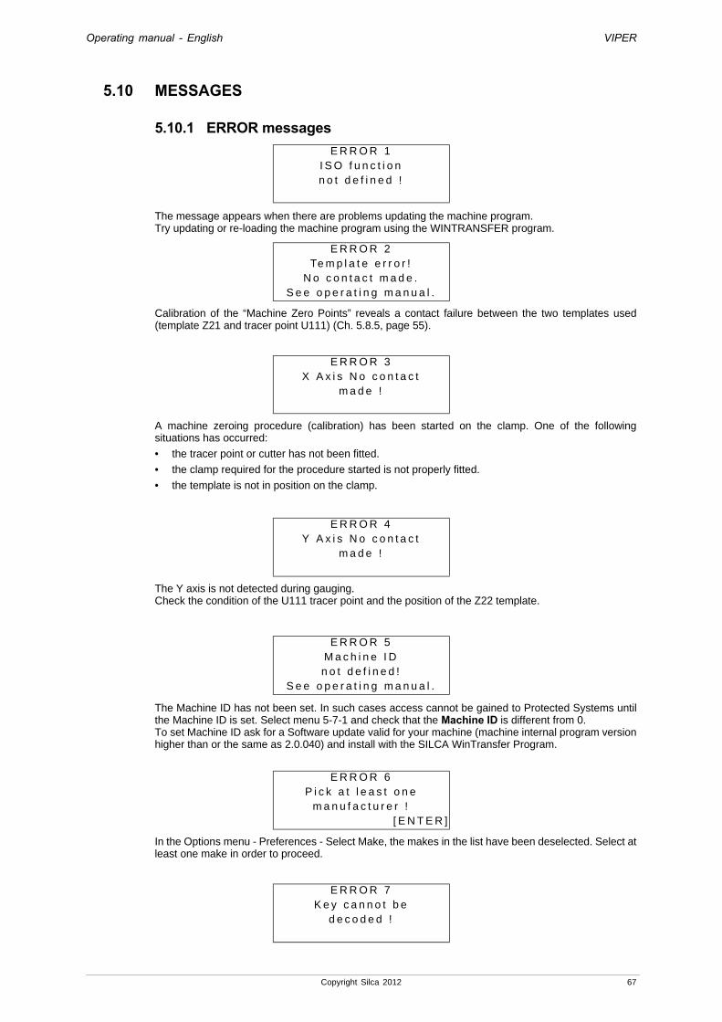
Operating manual - English VIPER
5.10 MESSAGES
5.10.1 ERROR messages
The message appears when there are problems updating the machine program. Try updating or re-loading the machine program using the WINTRANSFER program.
Calibration of the “Machine Zero Points” reveals a contact failure between the two templates used (template Z21 and tracer point U111) (Ch. 5.8.5, page 55).
A machine zeroing procedure (calibration) has been started on the clamp. One of the following situations has occurred:
• the tracer point or cutter has not been fitted.
• the clamp required for the procedure started is not properly fitted.
• the template is not in position on the clamp.
The Y axis is not detected during gauging.Check the condition of the U111 tracer point and the position of the Z22 template.
The Machine ID has not been set. In such cases access cannot be gained to Protected Systems until the Machine ID is set. Select menu 5-7-1 and check that the Machine ID is different from 0.To set Machine ID ask for a Software update valid for your machine (machine internal program version higher than or the same as 2.0.040) and install with the SILCA WinTransfer Program.
In the Options menu - Preferences - Select Make, the makes in the list have been deselected. Select at least one make in order to proceed.
E R R O R 1I S O f u n c t i o nn o t d e f i n e d !
E R R O R 2Te m p l a t e e r r o r !
N o c o n t a c t m a d e .S e e o p e r a t i n g m a n u a l .
E R R O R 3X A x i s N o c o n t a c t
m a d e !
E R R O R 4Y A x i s N o c o n t a c t
m a d e !
E R R O R 5M a c h i n e I Dn o t d e f i n e d !
S e e o p e r a t i n g m a n u a l .
E R R O R 6P i c k a t l e a s t o n e
m a n u f a c t u r e r ![ E N T E R ]
E R R O R 7K e y c a n n o t b e
d e c o d e d !
Copyright Silca 2012 67
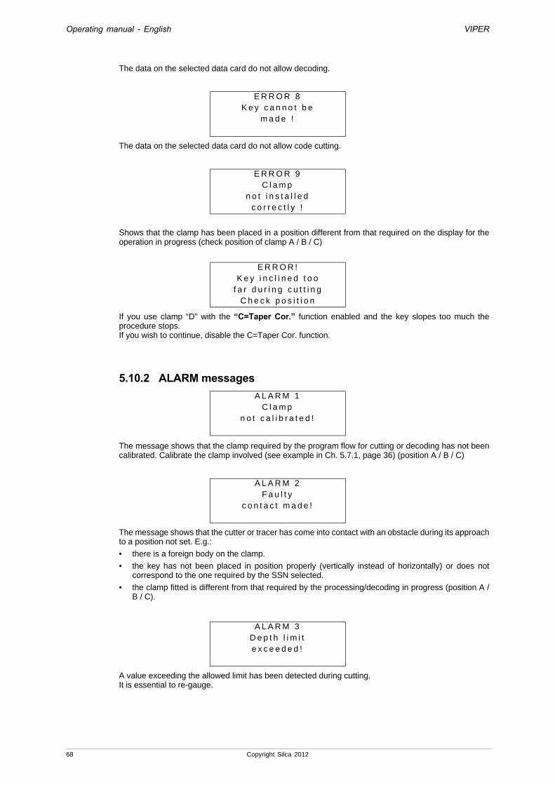
Operating manual - English VIPER
The data on the selected data card do not allow decoding.
The data on the selected data card do not allow code cutting.
Shows that the clamp has been placed in a position different from that required on the display for the operation in progress (check position of clamp A / B / C)
If you use clamp “D” with the “C=Taper Cor.” function enabled and the key slopes too much the procedure stops.If you wish to continue, disable the C=Taper Cor. function.
5.10.2 ALARM messages
The message shows that the clamp required by the program flow for cutting or decoding has not been calibrated. Calibrate the clamp involved (see example in Ch. 5.7.1, page 36) (position A / B / C)
The message shows that the cutter or tracer has come into contact with an obstacle during its approach to a position not set. E.g.:
• there is a foreign body on the clamp.
• the key has not been placed in position properly (vertically instead of horizontally) or does not correspond to the one required by the SSN selected.
• the clamp fitted is different from that required by the processing/decoding in progress (position A / B / C).
A value exceeding the allowed limit has been detected during cutting.It is essential to re-gauge.
E R R O R 8K e y c a n n o t b e
m a d e !
E R R O R 9C l a m p
n o t i n s t a l l e dc o r r e c t l y !
E R R O R !K e y i n c l i n e d t o o
f a r d u r i n g c u t t i n gC h e c k p o s i t i o n
A L A R M 1C l a m p
n o t c a l i b r a t e d !
A L A R M 2F a u l t y
c o n t a c t m a d e !
A L A R M 3D e p t h l i m i te x c e e d e d !
68 Copyright Silca 2012
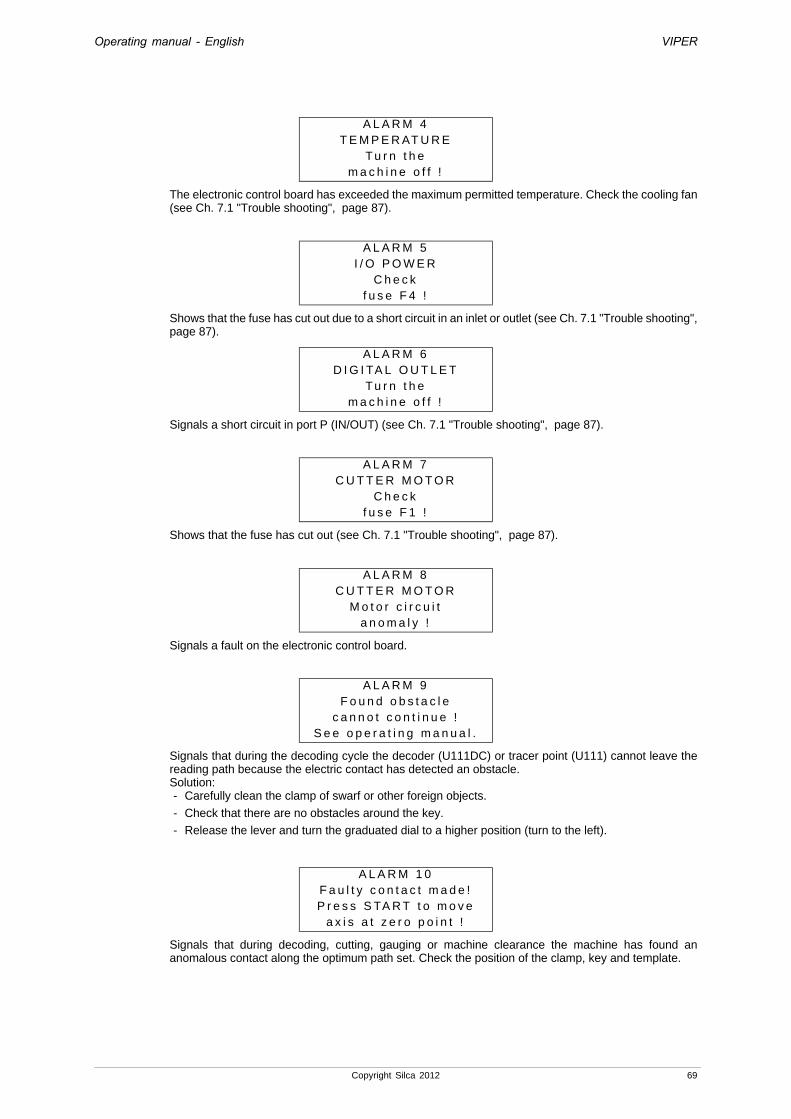
Operating manual - English VIPER
The electronic control board has exceeded the maximum permitted temperature. Check the cooling fan (see Ch. 7.1 "Trouble shooting", page 87).
Shows that the fuse has cut out due to a short circuit in an inlet or outlet (see Ch. 7.1 "Trouble shooting", page 87).
Signals a short circuit in port P (IN/OUT) (see Ch. 7.1 "Trouble shooting", page 87).
Shows that the fuse has cut out (see Ch. 7.1 "Trouble shooting", page 87).
Signals a fault on the electronic control board.
Signals that during the decoding cycle the decoder (U111DC) or tracer point (U111) cannot leave the reading path because the electric contact has detected an obstacle. Solution:- Carefully clean the clamp of swarf or other foreign objects.
- Check that there are no obstacles around the key.
- Release the lever and turn the graduated dial to a higher position (turn to the left).
Signals that during decoding, cutting, gauging or machine clearance the machine has found an anomalous contact along the optimum path set. Check the position of the clamp, key and template.
A L A R M 4T E M P E R AT U R E
Tu r n t h em a c h i n e o f f !
A L A R M 5I / O P O W E R
C h e c kf u s e F 4 !
A L A R M 6D I G I TA L O U T L E T
Tu r n t h em a c h i n e o f f !
A L A R M 7C U T T E R M O T O R
C h e c kf u s e F 1 !
A L A R M 8C U T T E R M O T O R
M o t o r c i r c u i ta n o m a l y !
A L A R M 9F o u n d o b s t a c l e
c a n n o t c o n t i n u e !S e e o p e r a t i n g m a n u a l .
A L A R M 1 0F a u l t y c o n t a c t m a d e !P r e s s S TA R T t o m o v e
a x i s a t z e r o p o i n t !
Copyright Silca 2012 69
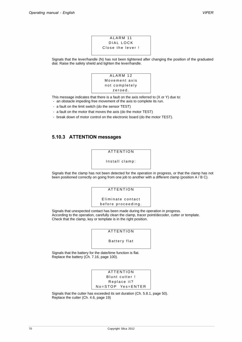
Operating manual - English VIPER
Signals that the lever/handle (N) has not been tightened after changing the position of the graduated dial. Raise the safety shield and tighten the lever/handle.
This message indicates that there is a fault on the axis referred to (X or Y) due to:- an obstacle impeding free movement of the axis to complete its run.
- a fault on the limit switch (do the sensor TEST)
- a fault on the motor that moves the axis (do the motor TEST)
- break down of motor control on the electronic board (do the motor TEST).
5.10.3 ATTENTION messages
Signals that the clamp has not been detected for the operation in progress, or that the clamp has not been positioned correctly on going from one job to another with a different clamp (position A / B C).
Signals that unexpected contact has been made during the operation in progress.According to the operation, carefully clean the clamp, tracer point/decoder, cutter or template.Check that the clamp, key or template is in the right position.
Signals that the battery for the date/time function is flat.Replace the battery (Ch. 7.16, page 100).
Signals that the cutter has exceeded its set duration (Ch. 5.8.1, page 50).Replace the cutter (Ch. 4.6, page 19)
A L A R M 11D I A L L O C K
C l o s e t h e l e v e r !
A L A R M 1 2M o v e m e n t a x i sn o t c o m p l e t e l y
z e r o e d .
AT T E N T I O N
I n s t a l l c l a m p :
AT T E N T I O N
E l i m i n a t e c o n t a c tb e f o r e p r o c e e d i n g .
AT T E N T I O N
B a t t e r y f l a t
AT T E N T I O NB l u n t c u t t e r !
R e p l a c e i t ?N o = S T O P Ye s = E N T E R
70 Copyright Silca 2012
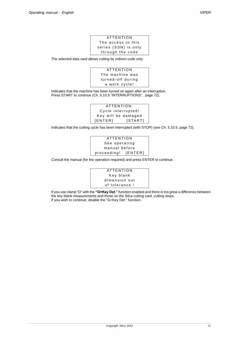
Operating manual - English VIPER
The selected data card allows cutting by indirect code only.
Indicates that the machine has been turned on again after an interruption.Press START to continue (Ch. 5.10.5 "INTERRUPTIONS", page 72).
Indicates that the cutting cycle has been interrupted (with STOP) (see Ch. 5.10.5, page 72).
Consult the manual (for the operation required) and press ENTER to continue.
If you use clamp “D” with the “G=Key Det.” function enabled and there is too great a difference between the key blank measurements and those on the Silca cutting card, cutting stops. If you wish to continue, disable the “G=Key Det.” function.
AT T E N T I O NT h e a c c e s s t o t h i s
s e r i e s ( S S N ) i s o n l yt h r o u g h t h e c o d e
AT T E N T I O NT h e m a c h i n e w a st u r n e d - o f f d u r i n g
a w o r k c y c l e !
AT T E N T I O N :C y c l e i n t e r r u p t e d !
K e y w i l l b e d a m a g e d[ E N T E R ] [ S TA R T ]
AT T E N T I O NS e e o p e r a t i n gm a n u a l b e f o r e
p r o c e e d i n g ! [ E N T E R ]
AT T E N T I O NK e y b l a n k
d i m e n s i o n o u to f t o l e r a n c e !
Copyright Silca 2012 71

Operating manual - English VIPER
5.10.4 Various messages
Appears
• If the template is not found during gauging.
• If the key is not in the clamp.
Appears
• if the decoder is broken or missing,
• if the decoder is not properly gauged (decoder too high),
• if the clamp is installed in a different position (A, B or C),
• if the clamp is not installed, (***) = A, B or C
If the previous operation required the dial to be in a position different from 5 (e.g. 6) and the operator forgets to take the dial back to position (5), the display will show the message:
Release the lever (N) turn the depth regulating (O) dial by hand and check that it is in position 5 (you should hear a click).
5.10.5 INTERRUPTIONS• WHAT TO DO IF THE DISPLAY SHOWS:
Indicates that the machine has been turned on again after an interruption.Press START or ENTER to continue; the display will show:
Raise the safety shield,loosen the lever/handle (N).Turn cutter chuck dial to the left until it reaches position 16 (you will feel position it clicks).Turn the clamp (F) knob and remove the key.Turn the cutter chuck dial to the right until it reaches its original position.Tighten the lever/handle (N).Lower the safety shield and press START.The display will show first:
then return to the initial menu.
X A X I S E R R O RN o c o n t a c t
m a d e !
E R R O RC l a m p ( * * * )
n o t i n s t a l l e dc o r r e c t l y !
U n l o c k t h e l e v e r a n dr e g u l a t e t h e d i a l
t o p o s i t i o n 5[ S TA R T ]
AT T E N T I O NT h e m a c h i n e w a st u r n e d - o f f d u r i n g
a w o r k c y c l e !
I t i s r e q u e s t e d t oz e r o o u t t h e a x e s
P r e s s [ S TA R T ]t o p r o c e e d .
P o s i t i o n i n gi n p r o g r e s s !
72 Copyright Silca 2012

Operating manual - English VIPER
• WHAT TO DO IF THE DISPLAY SHOWS:
Indicates that the cutting cycle has been interrupted (with STOP). Press the START button to turn on the cutter again. The upper carriage will make a straight run towards the operator in order to leave the cutting operation. The key will be a reject.Press the ENTER button; the display will show:
Raise the safety shield,loosen the lever/handle (N).Turn the cutter chuck dial to the left until it reaches position 16 (you will feel position it clicks).Turn the clamp (F) knob and remove the key.Turn the cutter chuck dial to the right until it reaches its original position.Tighten the lever/handle (N).Lower the safety shield and press START.The display will show first:
AT T E N T I O NC y c l e i n t e r r u p t e d !
K e y w i l l b e d a m a g e d[ E N T E R ] [ S TA R T ]
S e e o p e r a t i n g m a n u a lt o a v o i d a m i s c u t
k e y. [ S TA R T ]
P o s i t i o n i n gi n p r o g r e s s !
Copyright Silca 2012 73

Operating manual - English VIPER
5.11 WINTRANSFER PROGRAM FOR LOADING/UPDATING THE MACHINE PROGRAMThe machine comes with an internal program loaded and tested in workshops. The operator does not therefore need to carry out any operations.Only in the situations described below will the WinTransfer Program allow the machine to be re-set.
Here is a list of the situations that require the use of the WinTransfer Program.
• SILCA update for program or machine data
1) Connect the PC to the machine with the serial cable provided.2) Turn on the machine.3) Install the WinTransfer Program update on your personal computer, following the instructions in the
program.
• Replacement of the electronic board (see Ch. 7.4) or loss of machine program
1) use the machine keypad to enter the serial number found on the data plate on the back of the machine (see Ch. 5.9.1).
2) install the latest version of the WinTransfer Program on your personal computer.3) calibrate the machine according to the instructions in the manual, as follows:
The machine is now calibrated and ready for operation.
Carry out calibration in the way described in Ch. 5.8.5 "Machine Zero Points", page 55.Calibrate the clamp (Ch. 5.7.1, page 36).Continue by re-calibrating all the remaining clamps.
74 Copyright Silca 2012

Operating manual - English VIPER
5.12 CUTTING FLAT VEHICLE KEYS WITH THE CLAMP “D” SET
Fig. 55 - Clamp “D” set
5.12.1 Initial operation1) Check that the machine SW update is 1.2.018 DB 9.0 or later. If the machine is not updated, use
Wintransfer (CD provided in the clamp “D” set). See Ch. 5.11 for the procedure.
2) Install clamp “D” (see instructions in Ch. 4.4).
3) Remove the existing decoder U111DC and install the new vehicle key decoder U113DC.
Attenzione: if you are in possession of clamp “D” you may use tracer point U113 and the new vehicle key decoder U113DC, for all systems.
Decoder U113Decoder U113DC
Cutter H158 Z3 template
Insert 3-4
for vehicle keys CD Wintransfer
Insert 1-2 Side 1
Side 2
Side 3
Side 4
Insert 5-6 Side 5
Side 6
Copyright Silca 2012 75

Operating manual - English VIPER
76 Copyright Silca 2012
5.12.2 Clamp “D” calibration
Attention: Automatic Calibration is required only for D-1 clamp. For clamps D-2, D-3, D-4, D-5, D-6 see Ch.5.12.3, page 77 .
1) Select “CALIBRATION” and press ENTER.2) Select “CLAMPS” and press ENTER.
3) Select “D” and press ENTER. The display will show:
4) Check that the ring nut is on position 6.5) Check that tracer point U113 is installed.6) Check that insert 1-2 is fitted with position 1 towards the operator (fig. 56).7) Fit the key/template Z3 into the clamp, making sure the back is well aligned on the bottom and the
key stop is all the way up against position “0” (fig. 57).
Fig. 56
Fig. 57
8) Lower the safety shield and press START.
C l a m p s 1 : A 2 : B 3 : C 4 : D
C l a m p : D - 1A d j u s t m e n t :
X = + 0 0 Y = + 0 0To c a l i b r a t e [ S TA R T ]
C l a m p : D - 1T e m p l . : Z 3 P o s . : 0
S e e o p e r a t i n g m a n u a l [ E N T E R ]
C l a m p : D - 1 D i a l : 6 T r a c e r : U 1 1 3
S e e o p e r a t i n g m a n u a l [ S TA R T ]
F5

Operating manual - English VIPER
Copyright Silca 2012 77
- Start automatic clamp calibration by electrical contact.
The display will show:
- At the end the following message (for example) will appear:
Press [ENTER] to save the automatic adjustments to the default values.Attention: if you press [STOP] the new measurements will not be saved and the previous calibration settings
will remain valid.
- If this is not the case the display will show an error message:
In this case you MUST repeat the procedure taking care to perform all the steps described; particularlychecking the proper position of the clamp (Ch. 4.4, page 18).Lack of this condition may affect calibration.
Note: calibration will be accepted only if the variations remain within a range of -50 or +50 hundredths of a mm.
5.12.3 User adjustments - clamp “D”
The operator can make manual adjustments to the theoretical references or key stop points by enteringvalues for the X and Y parameters.This will vary the results of the cutting operation in the way shown in .Select the function from the main menu by placing the cursor on “4 - Calibrations”Select the menu “1 - Clamps”.Select clamp D.
• Press SHIFT + ENTER to go from one clamp to the other.
Note: clamps D-2, D-3, D-4, D-5 and D-6 accept only manual adjustments. For further details see Ch. 5.7.5.
Place the cursor at the side of the parameter to alter with the arrows [up/down] or [ENTER] and change the parameters with the following keys:
Fig. 58
C l a m p : D - 1D e t e c t i o n
i n p r o g r e s s !
C l a m p : D - 1X = - 0 2 Y = + 0 1
s a l v a r e i d a t i ?N o = S T O P Ye s = E N T E R
S u p e r a t o i l l i m i t ed i t o l l e r a n z a
X = - 0 2 Y = + 4 2S e e o p e r a t i n g m a n u a l .
C l a m p : D - 2A d j u s t m e n t :
X = + 0 0 Y = + 0 0To c a l i b r a t e [ S TA R T ]
SHIFT + [up arrow]Increases the value within +50 hundredths of a mm
SHIFT + [down arrow]Decreases the value within - 50 hundredths of a mm
CLEAR To zero the value
-Y
+Y
-X +X

Operating manual - English VIPER
[ENTER] in the last field allows you to quit the window and save the alterations made:
Attention: if you press [STOP] the new measurements will not be saved and the previous calibration settings will remain valid.
5.12.4 Decode and Copy - clamp “D”IMPORTANT: decoding keys in anodized aluminium, plastic or any key lacking electric conductivity IS NOT ALLOWED! For keys of these types use the “Key-cutting” function only.
Below is a description of all the steps needed to decode and cut a key. Choose the function from the main menu and position the cursor on “0-Decode and Copy”.
Press ENTER, the display will show:
Do a search by SSN or Make (see Ch. 5.1 "Symbols and terminology", page 20).
Example by make: LAND ROVER
• Press the key [right-hand arrow] to place the cursor next to the “Make” field.You do not need to enter the whol e name, the first letters will be enough; the na me of the closest MAKE in alphabetical order will appear automatically;
• You can use the arrows [up/down] to scroll the sequence of MAKES in alphabetical order.
• Use [CLEAR] to delete the text entered.
• The last line in the window gives the results of the search:- “[08] List = ENTER”: 8 SSN found, press [ENTER] to see the list.
Note: the letter D in front of a description indicates that the system requires clamp “D”.
S a v e a d j u s t m e n t ?
N o = S T O P Ye s = E N T E R
0 - D e c o d e a n d C o p y1 - I n s e r t t h e C u t s2 - L i s t o f C o d e s3 - Q u e u e f r o m P C
4 - C a l i b r a t i o n s 5 - M a i n t e n a n c e6 - O p t i o n s
S S N = ( D e c o d . )M F G == >
S S N = ( D e c o d . )M F G = L A= > L A N D R O V E R[ 0 8 ] L i s t = E N T E R
L A N D R O V E R [ 0 8 ]1 : 1 3 6 1 D A F2 : 9 7 / 9 1 L A N D R O V E R3 : C R G 8 5 + a n d U S T R > >
78 Copyright Silca 2012

Operating manual - English VIPER
Example with cursor in position 1:• To view other information about the SSNs found, hold down the key (right-hand arrow). For
example, with the cursor in position 1:
Press ENTER to continue; the display will show:
1) Raise the safety shield, loosen the handle (N) and turn the depth regulating ring nut (O) so that the number 6 corresponds with the spindle support notch () (it will click into place). Block the handle (N).
2) Fit insert 1-2 in the clamp with notch 2 towards the operator (fig. 59).3) Fit the key to be decoded in the clamp so that it lies flat with the stop
up against Stop 0.4) Secure the key by tightening the knob (F5) to the right.
Fig. 59
Fig. 60Close the safety shield and press [START] to begin decoding. If the safety shield is not closed, the following message will appear:
When the safety shield is lowered the following message will appear:
Press START to continue; the display will show an initial message:
S i l c a N r . 1 3 6 11 3 6 11 : D A F2 : F O R D E U
D E C O D EC l a m p . : D - 2 P o s . : 0T r a c e r D i a l : 6
[ S TA R T ]
C l o s es h i e l d !
C o n t i n u e ?
N o = S T O P Ye s = S TA R T
D E C O D I N G I N P R O G R E S SS i d e : AA x i s : 1
O
F5
N
Copyright Silca 2012 79

Operating manual - English VIPER
At the end of the procedure the display will show the message (example):
ATTENTION:- Press [right-hand arrow] to move the cursor (on the same axis) into the various cutting
positions - Press [up arrow] to eliminate the cut in the cursor position (an empty space is created) and
the cutting positions remain the same [8]- Press (CLEAR/COPY) to e liminate cuts (the machine considers consecutive cuts and not
empty spaces) and the cutting positions decrease [7]
Press ENTER and continue with cutting, performing the operations described in capitolo Ch. 5.12.5 "Insert Cuts - clamp “D”".
5.12.4.1 Key copying by measurements readAfter decoding the operator can choose to reproduce the key by measurements read (EXACT COPY) or by the decoded measurements (COPY BY CUTTING CARD).
5.12.5 Insert Cuts - clamp “D”Below are described all the steps needed to cut a key when the SSN (Silca Serial Number) or Make associated to the Lock System is known.Choose the function from the main menu and place the cursor on “1-Insert cuts”.
Note: do a search by SSN or Make (see Ch. 5.1 "Symbols and terminology", page 20).
Example by Make: LAND ROVER
• Press [right-hand arrow] to place the cursor next to “Make”.You do not need to enter the whol e name, the first letters will be enough; the na me of the closest MAKE in alphabetical order will appear automatically;
• You can use the arrows [up/down] to scroll the sequence of MAKES in alphabetical order.
• use [CLEAR] to delete the text entered.
• The last line in the window gives the result of the search:
A x i s : 1 o f 2S i d e s : A B4 4 2 2 3 3 4 4( 1 2 3 4 ) [ 8 ]
W a n t t o c o p y t h e k e yu s i n g t h e m e a s u r e m .
j u s t r e a d ?N o = S T O P Ye s = E N T E R
0 - D e c o d e a n d C o p y1 - I n s e r t t h e C u t s2 - L i s t o f C o d e s3 - Q u e u e f r o m P C
4 - C a l i b r a t i o n s 5 - M a i n t e n a n c e6 - O p t i o n s
S S N = ( C u t )M F G = L= > L A N D R O V E R[ 0 8 ] L i s t = E N T E R
?
80 Copyright Silca 2012

Operating manual - English VIPER
- “[08]) List = ENTER”: 2 SSN found, press [ENTER] to see the list.
• To view other information about the SSNs found, hold down the key [right-hand arrow]. With the cursor in position 1 press ENTER:
Use the alphanumerical keys to enter only the symbols given in brackets (1, 2, 3, 4) that correspond to the cutting depths admitted for the chosen key.
- If a different symbol is entered, you will hear a long warning beep.
- To skip cuts (empty cuts or skipped cuts) press [up arrow].
- The value in square brackets [1] corresponds to the position (pitch) of the cut;
- To move the cursor horizontally press [right-hand arrow];
(at the end of the line the cursor will automatically go back to the beginning).To view or enter cuts on the key axes, press [down arrow].
Enter the cuts, e.g.:
Press ENTER to continue with the cutting operations.The display will show:
Cutting instructions continue on page 82.
5.12.5.1 Cutting flat keys (descriptions)
Fig. 61Fig. 62
L A N D R O V E R [ 0 8 ]1 : 1 3 6 1 D A F2 : 8 7 / 9 1 L A N D R O V E R3 : C R G 8 5 + a n d U S T R
A x i s : 1S i d e s : A B. . . . . . . .( 1 2 3 4 ) [ 1 ]
A x i s : 1S i d e s : A B2 2 3 3 4 4 3 3( 1 2 3 4 ) [ 8 ]
C l a m p . : D - 2 P o s . : 0 C u t t e r : H 1 5 8 D i a l : 6 F = B r a s s G = K e y D e t . P c s . 1 / 1 [ S T A R T ]
?
?
4
Insert position 2
Insert position 1 Insert position 3
Insert position 4
Insert position 5
Insert position 6
2
3
4
6
Key stop position (Stop)
Copyright Silca 2012 81

Operating manual - English VIPER
Clamp: D-2Clamp required - Insert position (fig. 61)
Pos.: 0Key stop position (fig. 62)
Cutter: H158Cutter required for system involved.
Dial: 6Dial (O) position (fig. 63)
Pcs. 1/1Number of pieces to cut
Fig. 63
5.12.5.2 Change key material function - F=Brass/SteelPress F to select the material of the key to be cut.
5.12.5.3 Key blank measurement reading function - G=Key Det. This function is used to read the measurement of the key blank (stem width) in order to adapt cutting to the key blank in use. If this function is enabled it is automatically applied only to keys with two sides.
Press G to enable the function.When the words “G=Key Det. f”lash the function is enabled.
Fig. 64
With the “G=Key Det. F”unction enabled, if there is too great a difference between the key blank measurements and those on the Silca cutting card, cutting stops and the following message ap-pears:
If you wish to continue, disable the “G=Key Det.” function.
Cutting instructions (continue from page 81)1) Raise the safety shield, loosen the knob (F5) and remove the original key. Fit the key blank into the
clamp (Stop 0) and tighten the knob (F5).2) Lower the safety shield.3) If the number of keys to be cut is different from 1, enter (using the alphanumerical keys on the
keypad) the number of keys required (pieces) [1-255].
Attention: the operator is responsible for installing the right cutter as there is no electronic device to warn of any errors!!!
4) Press START to begin cutting.
5) At the end of side A the display will show:
AT T E N T I O NK e y b l a n k d i m e n s i o n
o u t o f r a n g e !
C U T T I N G I N P R O G R E S SC o p y : 1 o f : 1
S i d e : A A x i s : 1B r a s s
C l a m p . : D - 2 P o s . : 0C u t t . : H 1 5 8 D i a l : 6C = Ta p e r C o r . S i d e : B [ S TA R T ]
6
O
82 Copyright Silca 2012

Operating manual - English VIPER
5.12.5.4 Key Inclination Adjustment Function C= Taper Cor. This function is used to check that the key has been properly positioned: this is because the cuts on side A make it difficult to align the key in the clamp.If enabled this function is automatically applied only to keys with double sides.To enable the function press C. When the words “C=Taper Cor.” flash the function is enabled.
Fig. 65
When the “C=Taper Cor.” function is enabled and the key is inclined too much, the procedure stops and the following message will appear:
If you still wish to continue, disable the “C=Taper Cor.” function.6) Raise the safety shield, loosen the knob (F5), remove the key and turn it 180°. Replace in the clamp
(Stop 0) and tighten the knob (F5).7) Lower the safety shield and press START.
At the end of the operation the display will show:
Press [ENTER] to proceed with another copy.Press [STOP] to end the operation.
E R R O R !K e y i n c l i n e d t o o
f a r d u r i n g c u t t i n gC h e c k p o s i t i o n
C U T T I N G I N P R O G R E S SC o p y : 1 o f : 1
S i d e : B A x i s : 1
C o p y : 1 o f : 2f i n i s h e d !
M o r e c o p i e s ?N o = S T O P Ye s = E N T E R
Side B
Copyright Silca 2012 83

Operating manual - English VIPER
5.12.6 Code Tables - clamp “D”The “CODE TABLES” menu is used to identify the SSNs with an associated code table using search criteria such as “Original Code” or the key MAKE-USE.When the SSN has been identified the key can be cut in the way described in Ch. 5.12.5 "Insert Cuts - clamp “D”", page 80.Choose the function from the main menu and position the cursor on “2- Code Tables”.Do a search by entering the code or Make (Ch. 5.1 "Symbols and terminology", page 20).
Example by Code: 8442
• Press [right-hand arrow] to place the cursor next to the “Code=” field.
• Enter the code “8442”.
• The search finds 12 series that use the code in question.The display will show:
The search for the code i n question is made in all the series relating to the MAKES enabled. The machine with its standard settings makes a search in all the series of codes.If you wish to filter code searches according to given Lock or Vehicle Makes follow the instructions on page 61 (cap. 5.9 "Options - 6", 5.9.2 "Preferences", “Preselezione Marche”). If the code in question belongs to a series but not the group of makes selected, a message will appear “Code not found” and the last line of the window will show the words “SHIFT + ?”. Press [SHIFT] and [?] to temporarily exclude the filter and extend the search to all makes so as to view the result without changing the “Make Preselection” setting.
Press ENTER to view the list of series involved.
Use the arrows [up/down] to move the cursor to select the required series, for example with cursor in pos. 2. Press ENTER; the display will show:
• To view other information about the SSNs found, hold down the [right-hand arrow] .
There are now 2 possibilities:
- Proceed with [SHIFT+ENTER] to follow the complete flow and see the cuts associated to the code in question. The cuts are already inserted and correspond to code 8442.
- Proceed with [ENTER] to skip some steps and go to the window that appears before cutting start.
Lower the safety shield and press START.
C o d e = 8 4 4 2M F G == >[ 1 2 ] L i s t a = E N T E R
C o d e = 8 4 4 2 [12] 1 : A A 0 0 - 7 T 5 1 G M < I > 9 4 +2 : 5 0 0 1 - 8 4 4 2 H O N D A 8 83 : 1 - 1 7 7 3 5 K ( 2 T - 9 W )
S i l c a N r : 1 3 4 8H O N D A 8 8 + I S U Z U 9 8 +1 - A C U R A2 - H O L D E N
C l a m p : D - 2 P o s . : 0C u t t . : H 1 5 8 D i a l : 6F = B r a s s G : K e y D e t .P c s . 1 / 1 [ S T A R T ]
?
?
84 Copyright Silca 2012
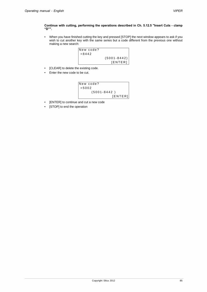
Operating manual - English VIPER
Continue with cutting, performing the operations described in Ch. 5.12.5 "Insert Cuts - clamp “D”".
• When you have finished cutting the key and pressed [STOP] the next window appears to ask if you wish to cut another key with the same series but a code different from the previous one without making a new search:
• [CLEAR] to delete the existing code.
• Enter the new code to be cut.
• [ENTER] to continue and cut a new code
• [STOP] to end the operation
N e w c o d e ? = 8 4 4 2 ( 5 0 0 1 - 8 4 4 2 ) [ E N T E R ]
N e w c o d e ? = 5 0 0 2
( 5 0 0 1 - 8 4 4 2 )[ E N T E R ]
Copyright Silca 2012 85

Operating manual - English VIPER
6 CLEANING• keep the o perational parts of the machine as clean as possible by brushing away the
chippings.• The clamp, detection pins, decoder, cutter and Z22 template must always be kept perfectly
clean.• under no circumstances use compressed air to clear the work zone of chippings as this will
blow them onto the moving parts.• Never use oily products or thinners for cle aning painted surfaces, clamps, electrical or
electronic connections.
86 Copyright Silca 2012

Operating manual - English VIPER
7 MAINTENANCEAttention: for repairs or replacement of parts for main tenance, the ‘CE’ mark is guaranteed only if original
spare parts provided by the manufacturer are used.Although the VIPER key-cutting machine does not require special maintenance, it is advisable to check and, if necessary, replace the parts subject to wear and electric/electronic parts (fuses, circuit boards, etc.) in the event of faulty operation.Replacement is simple and can be carried out by the operator consulting the instructions.
Attention: for normal servicing of the burnished mechanical parts, we recommend using lubricants o r protective oil, e.g. WD40 or similar. Do not apply to the parts used for electrical contact (clamps, decoders, cutters, gauging templates, etc.). Do not contaminate the electronic parts with the oil.Before starting any type of maintenance (checks or replacements) read the instructions below:
• never carry out maintenance with the machine switched on• always remove the mains plug• always remove the mains plug• use original spare parts (see ‘Spare Parts List’ provided with the machine).
7.1 TROUBLE SHOOTING
FAULT CHECK PROBABLE CAUSEMachine on, no message on display:
check if the rear fan is working:
YES
a) emergency button activated
b) faulty general fuses in power socket
c) master switch on back of machine in OFF position
d) disconnected supply wire
NO
a) fuse F3 on the electronic control board has cut out
b) loose connection wire between display and electronic board
c) display out of order
Cutter motor not working:
a) the closed protective shield is not making proper contact with the safety microswitch (see Ch. 7.10, page 97).
b) fuse F1 on the electronic control board cut out (see Ch. 7.3, page 90)
c) motor wire not properly connected to the connector (see.Ch. 7.4, page 91)
d) faulty electronic control board
The display shows “Cutting in progress, or decode, etc.” but the X-Y axes are immobile and none of the keys is enabled.
Check the fuse F2 (fig. 69, page 90) on the electronic control circuit board involved.
Use tests No 1-2 (Ch. 5.8.2, page 51) to check the X-Y axis motors
Check the X axis connecting cable (fig. 80, page 96)
The wiring connecting the X-Y axis motors to the electronic control board is not properly secured or the connectors are not fitted correctly (Ch. 7.4, page 91)
Electronic control circuit board faulty.
With shield closed display shows message “Close shield”
a) the closed protective shield is not making proper contact with the safety microswitch (see Ch. 7.10, page 97)
b) fuse F4 on the electronic control board has cut out (see Ch. 7.3, page 90)
Keypad not working (partially or completely)
a) the keypad connector is not properly connected to the interface board (fig. 66)
b) the wiring between the keypad/display and electronic control board is not properly attached to the relative connectors (see Ch. 7.4, page 91 and Ch. 7.5, page 92)
c) faulty keypad (see Ch. 7.5, page 92)
d) faulty electronic control board (see Ch. 7.4, page 91)
During clamp gauging or decoding the U111 tracer point bumps repeatedly against the template or against the key.
the earth wire (C2) on the cutter (fig. 86, page 98) is detached or broken.
the wire connecting the connector (J14) for the electronic control board is not properly fitted into the relative connector (fig. 69, page 90).
there is swarf on the top part of the cutter shaft.
electronic control circuit board faulty.
Key-cutting machine fails to communicate with computer
a) wiring between the 9-pin serial port and electronic control board badly fixed or disconnected (see Ch. 7.4, page 91)
b) serial wire between key-cutting machine (serial port fig. 5, page 6) and computer faulty or disconnected
c) faulty computer serial port
d) electronic control board faulty (see Ch. 7.4, page 91)
Copyright Silca 2012 87

Operating manual - English VIPER
Fig. 66
Display shows message ‘TEMPERATURE ALARM, turn the machine off”.
Check whether the fan on the back of the key-cutting machine is working:
Not working
a) fan faulty or badly wiredb) faulty electronic control board (see Ch. 7.4, page 91)
Working a) faulty electronic control board (see Ch. 7.4, page 91)
Display shows message ‘CUTTER MOTOR ALARM, check Fuse F1”.
a) fuse F1 on the electronic control board cut out (see Ch. 7.3, page 90).
b) cutter protective cover microswitch cut out or disconnected (see Ch. 7.10, page 97 and Ch. 7.11, page 97).
c) cutter motor wiring disconnected.
d) internal fault on the electronic control board (see Ch. 7.4, page 91).
The top X axis carriage moves to the left or right and bumps against the machine end of run.
Use test No 5 (Ch. 5.8.2, page 51) to check operation of the sensor.
Check the fuse F4 (fig. 69, page 90) on the electronic control board.
Check the X axis connecting cable (J1) (fig. 80, page 96).
electronic control board faulty.
The bottom Y axis carriage moves towards the operator or the machine face and bumps against the end of run.
Use test No 6 (Ch. 5.8.2, page 51) to check operation of the sensor.
Check the fuse F4 (fig. 69, page 90) on the electronic control board.
electronic control board faulty.
FAULT CHECK PROBABLE CAUSE
88 Copyright Silca 2012

Operating manual - English VIPER
7.2 BELT REPLACEMENT AND TENSION ADJUSTMENT1) Turn off the machine and unplug.2) open the top compartment (Ch. 7.6, page 93).3) loosen (without removing) the grub screw (Y2) that secures the belt tightening pulley (fig. 67).4 a) tightening:- increase belt tension by means of the socket head screw (Y3), using the allen key provided.
4 b) replacement:- loosen the belt by means of the socket head screw (Y3), using the allen key provided.
- remove the belt and replace it.
- tighten by means of the socket head screw (Y3) using the allen key provided.
5) lock the belt tightening pulley by tightening the socket head screw (Y2).6) reposition the belt cover.
Fig. 67
Y2
Y3
Copyright Silca 2012 89

Operating manual - English VIPER
7.3 FUSE CHECK AND REPLACEMENTFuses should be checked with an instrument for measuring their continuity (tester, ohmmeter, multimeter, etc.) as they may appear to be in good condition to the naked eye even when they are electrically faulty. Fuses must always be replaced with others of the same type (rapid or delayed) and with the same amps, as given in the manual.There are 6 fuses in the VIPER key-cutting machine.• 2 fuses:6,3 Amps rapid (230V)10 Amps rapid (120V)8 Amps rapid (100V)They are situated in the power socket on the back of the machine, next to the switch (fig. 68). They protect the machine from power variations and short circuits.To check and replace when necessary, proceed as follows:
1) turn off the machine and unplug.2) use a screwdriver to open the flap covering
the socket, remove the fuses and replace if necessary.
Fig. 68
• 4 fuses: F1, F2, F3 e F4F1: 10 Amps delayed
- protects the cutter motor and its control electronics (230V a.c.)F2: 6,3 Amps delayed
- protects the step motors and their control electronics (+32V d.c.)F3: 4 Amps delayed
- protects the logic control circuits on the microprocessor board (+5V d.c.)F4: 2 Amps delayed
- protects the digital output circuits for the low voltage controls and the sensor inlets (+24V d.c.)Those situated on the electronic circuit board inside the base (fig. 69), protect the board from short circuits. To check and replace when necessary, proceed as follows:
1) turn the machine off and unplug it from its power supply cable.2) remove the bottom plate (Ch. 7.8, page 94).3) check and replace the fuses if necessary, in the way described below:To remove the fuse:- press the fuse cap with your fingers and turn it counter clockwise.
To fit the new fuse:- carefully position the fuse back into place, then gently press the fuse cap downwards turning it
clockwise.
Fig. 69
F2
F3
F1
F4
to open fuse cap
to close fuse cap
scheda elettronica
J14
90 Copyright Silca 2012

Operating manual - English VIPER
7.4 ELECTRONIC CIRCUIT BOARD REPLACEMENTReplace the electronic circuit board in the following way:
1) turn off the machine and unplug.2) remove the bottom panel (Ch. 7.8, page 94).3) disconnect all the wires from the board.
Fig. 70
4) loosen the nuts (E) and remove the board.5) fit the new board on the threaded pins and screw down the nuts, re-connect all the wires (each
connector is polarized and cannot be placed in the wrong position).6) replace the bottom plate and re-position the machine on the workbench.7) turn on the machine and launch the WIN-TRANSFER PROGRAM in order to transmit the software. 8) carry out the calibration operations (Ch. 5.8.5 "Machine Zero Points", page 55 and Ch. 5.7.1
"Automatic calibration of clamp", page 36).
E
Copyright Silca 2012 91

Operating manual - English VIPER
7.5 KEYPAD/DISPLAY REPLACEMENT1) turn off the machine and unplug.2) remove the display stand by unscrewing the 2 fixing screws (B1) (fig. 71).3) detach the wire and earth wire from the keypad (fig. 72).4) loosen the keypad fixing nuts and remove from its stand.5) fit the new keypad/display, repeating the operations described above in reverse order.
Fig. 71
Fig. 72
B1
92 Copyright Silca 2012

Operating manual - English VIPER
7.6 ACCESS TO TOP COMPARTMENTTo gain access to the top compartment, proceed as follows:
1) turn off the machine and unplug.2) loosen the 2 screws (V1) and remove the protective shield.3) loosen the 5 screws (G1) and remove the top cover (fig. 74).
Fig. 73
Fig. 74
V1
G1
G1
G1
Copyright Silca 2012 93

Operating manual - English VIPER
7.7 ACCESS TO REAR COMPARTMENTTo gain access to the rear compartment, proceed as follows:
1) turn off the machine and unplug.2) loosen the 6 screws (M1) securing the rear plate (fig. 75) and remove.
Fig. 75
7.8 ACCESS TO LOWER COMPARTMENTTo gain access to the lower compartment, proceed as follows:
1) turn off the machine and unplug.2) turn the machine onto its back.3) remove the bottom plate by loosening the 8 fixing screws (L1) (fig. 76).
Fig. 76
M1
L1
94 Copyright Silca 2012

Operating manual - English VIPER
7.9 SENSOR REPLACEMENT
REPLACING THE BOTTOM AXIS (Y) SENSOR
1) Turn off the machine and unplug.2) remove the display stand by unscrewing the 3 fixing screws (B1) (fig. 71, page 92).3) detach the wire and earth wire from the keypad (fig. 72, page 92).4) remove the bottom plate (Ch. 7.8, page 94).5) disconnect the bottom axis (Y) sensor from the circuit board.6) loosen the screw (L5) and remove the plate (sensor).7) check the “Y” measurement.8) loosen the nut (L3), loosen the sensor from the plate and remove (fig. 78).9) loosen the 3 screws (B4) to remove the front cover on the lower carriage (fig. 79).10) place the new sensor in position and screw down to the “Y” measurement (fig. 78), secure with the
nut (L3).11) connect the sensor connector (L6) to the circuit board.12) replace the plate (sensor) in position and tighten the screw (L5).
Fig. 77
Fig. 78
Fig. 79
L5
L6
0,1 / 0,4 mm
L2Y axis sensor
L3L5
measurement “Y”
B4
Copyright Silca 2012 95
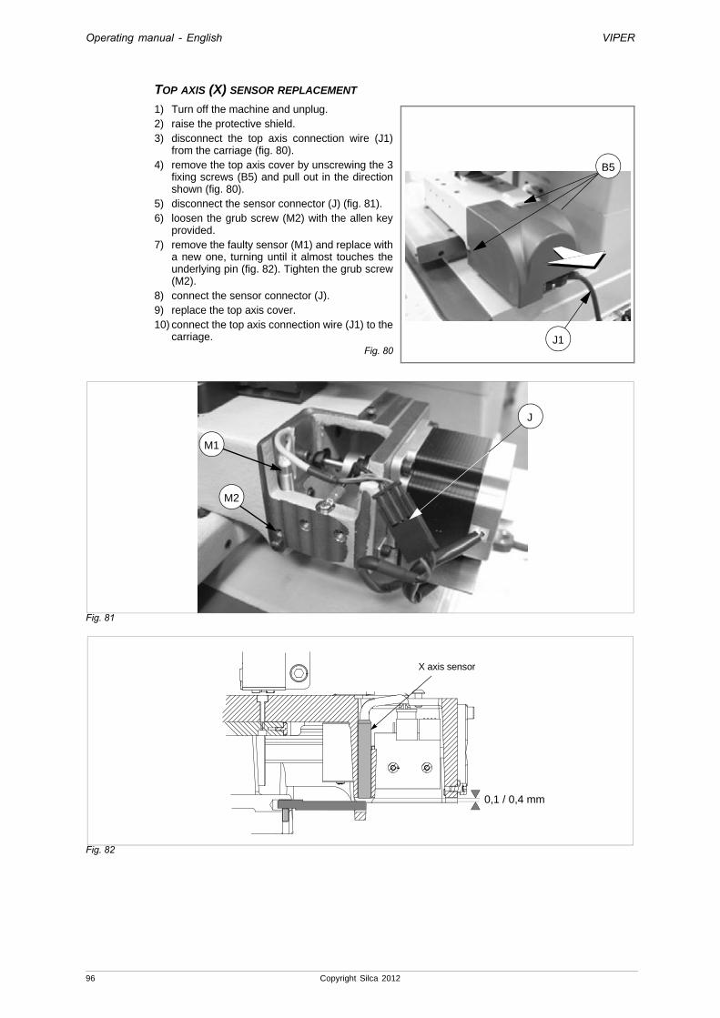
Operating manual - English VIPER
TOP AXIS (X) SENSOR REPLACEMENT
1) Turn off the machine and unplug.2) raise the protective shield.3) disconnect the top axis connection wire (J1)
from the carriage (fig. 80).4) remove the top axis cover by unscrewing the 3
fixing screws (B5) and pull out in the direction shown (fig. 80).
5) disconnect the sensor connector (J) (fig. 81).6) loosen the grub screw (M2) with the allen key
provided.7) remove the faulty sensor (M1) and replace with
a new one, turning until it almost touches the underlying pin (fig. 82). Tighten the grub screw (M2).
8) connect the sensor connector (J).9) replace the top axis cover.10) connect the top axis connection wire (J1) to the
carriage.Fig. 80
Fig. 81
Fig. 82
J1
B5
M1
J
M2
X axis sensor
0,1 / 0,4 mm
96 Copyright Silca 2012
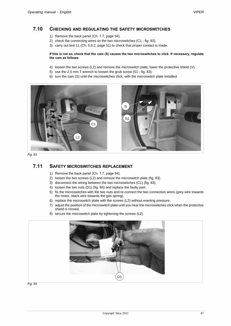
Operating manual - English VIPER
7.10 CHECKING AND REGULATING THE SAFETY MICROSWITCHES1) Remove the back panel (Ch. 7.7, page 94).2) check the connecting wires on the two microswitches (C1 - fig. 83).3) carry out test 11 (Ch. 5.8.2, page 51) to check that proper contact is made.
If this is not so, check that the cam (S) causes the two microswitches to click. If necessary, regulate the cam as follows:
4) loosen the two screws (L2) and remove the microswitch plate; lower the protective shield (V).5) use the 2,5 mm T wrench to loosen the grub screw (S1 - fig. 83).6) turn the cam (S) until the microswitches click, with the microswitch plate installed.
Fig. 83
7.11 SAFETY MICROSWITCHES REPLACEMENT1) Remove the back panel (Ch. 7.7, page 94).2) loosen the two screws (L2) and remove the microswitch plate (fig. 83).3) disconnect the wiring between the two microswitches (C1) (fig. 83).4) loosen the two nuts (D1) (fig. 84) and replace the faulty part.5) fix the microswitches with the two nuts and re-connect the two connection wires (grey wire towards
the motor, black wire towards the gas spring).6) replace the microswitch plate with the screws (L2) without exerting pressure.7) adjust the position of the microswitch plate until you hear the microswitches click when the protective
shield is moved.8) secure the microswitch plate by tightening the screws (L2).
Fig. 84
S1
S
L2
C1
D1
Copyright Silca 2012 97

Operating manual - English VIPER
7.12 DECODER (U111DC) REPLACEMENT1) Loosen the grub screw (K) (fig. 85).2) remove the broken decoder from its seat.3) place the new decoder in its seat, pushing it upwards against the end of run.4) tighten the grub screw (K).5) proceed with gauging (Ch. 5.7.3, page 44).
Fig. 85
7.13 RING NUT MICROSWITCH REPLACEMENT1) Open the top compartment (Ch. 7.6, page 93).2) loosen the 4 screws (C3) and remove the plate covering the microswitch (fig. 86).3) disconnect the microswitch connector (W).4) turn the lever/handle (N) anticlockwise to free the microswitch fin.5) loosen the 2 microswitch fixing screws (W1) and remove.6) connect the connector (W) to the new microswitch.7) place the new microswitch in position (free fin to the right) and secure with the 2 screws (W1).8) before tightening the two screws (W1) adjust the microswitch position and check with the special
test (Test 8, see Ch. 5.8.2, page 51). When locking the microswitch fin the lever/handle (N) should be positioned vertically downwards (fig. 86).
9) fix the cover plate with the 4 screws (C3).
Fig. 86
K
C3
W
N
W1
98 Copyright Silca 2012

Operating manual - English VIPER
7.14 MOTOR / CONDENSER REPLACEMENT 1) Turn off the machine and unplug. 2) open the top compartment (Ch. 7.6, page 93).3) turn the machine over onto its side.4) open the rear compartment (Ch. 7.7, page 94).5) open the bottom compartment (Ch. 7.8, page 94).Condenser:
a) loosen the fixing nut (Z1) and remove the washer and condenser.b) fit the new condenser and fix with the washer and nut.c) remove the cap (Z2) on the new condenser.d) remove the cap from the old condenser, detach the 2 connectors (a) and (b) paying careful atten-
tion to their position, and connect to the new condenser.e) replace the cap (Z2) on the new condenser.
Motor:f) cut the 4 nylon ties on the wiring.g) press on the connector grips (Z3) to remove them (fig. 88).h) remove the belt.i) loosen the screw (Y1) and remove the pulley (fig. 89).j) loosen the 4 screws (Y2) fixing the motor and remove (fig. 89).k) Install the new motor by carrying out in reverse the operations described above. If necessary, also
replace the condenser.
6) close the bottom compartment.7) close the rear compartment.8) close the upper compartment.
Fig. 87
Fig. 88
a
Z2
b
Z1
Z3
Z1
Copyright Silca 2012 99

Operating manual - English VIPER
Fig. 89
7.15 LIGHT BULB REPLACEMENT1) turn off the machine and unplug.2) raise the safety shield.3) remove the lampshade (H1), unscrewing it manually (fig. 90).4) unscrew the light bulb by hand (H) and remove.5) fit the new bulb by screwing it manually into the bulb holder.6) replace the lightshade (H1), screwing it down manually.
Fig. 90
7.16 CLOCK BATTERY REPLACEMENT1) turn off the machine and unplug.2) open the bottom compartment (Ch. 7.8, page 94).3) use a slim insulated tool to push the battery and remove it.4) fit the new battery into its seat, paying attention to the poles.
Fig. 91
Y2
Y1
H1
H
100 Copyright Silca 2012

Operating manual - English VIPER
8 DISPOSING OF MACHINETo dispose the machine, it must be rendered unusable by carrying out the operations listed below:• deactivation of the electricity supply;
• separation of the plastic and metal parts;
• remove the lithium battery from the electronic board;Attention: the lithium battery must be disposed in the special containers.
When these operations have been carried out the machine can be disposed of according to the current regulations in the country of use.
WASTE DISPOSAL
CEE standards lay down special regulations for waste disposal (*).
MACHINE
VIPER is a durable machine and is also re-usable.Recycling is an ecologically sound practice to be recommended.
PACKING
As the packing in which the VIPER key-cutting machine is transported is made of cardboard and wood it can be re-used if intact or used as fuel for the production of heat (e.g. wood-fired stoves) if dismantled.Warning! Take great care when dismantling the packing as it contains nails, the points of which will be exposed. Bend them down into the wood with a hammer or remove separately and dispose of them in an authorized metal recycling centre.As waste the packing is considered solid urban waste and must not be thrown into the environment but taken to the special collection centres.
WASTE DERIVING FROM KEY CUTTING
Waste deriving from key cutting is classified as special waste, but included in solid urban waste, considered as metal wool. Such waste must be disposed of in the special collection centres according to the classification assigned to them by current Italian and EEC law. The circumstances which transform metal residue from solid urban waste into contaminated or toxic noxious waste are listed in the appendices to current Italian and European Union regulations regarding disposal of such waste
INFORMATION FOR USERSas per art. 10 of Directive 2002/96/CE of 27/01/2003
regarding waste from electric and electronic appliances (RAEE),
• The symbol illustrated above, also found on the machine, indicates that it has been placed on the market and must be included in separate rubbish collection when the user wishes to dispose of it (including all components, sub-assemblies and consumables that are integrated in the product).
• For information about the collection system for such appliances please contact SILCA S.p.A. or another subject registered in the various National Rolls for other countries in the European Union. Household waste (or of similar origin) can be included in the separate collection system for urban waste.
• On purchasing a new appliance of equivalent type, the old one can be consigned to the dealer. The dealer will then contact whoever is responsible for collecting the appliance.
• Suitable separate collection of the unused appliance and its dispatch for treatment, recovery and environmentally compatible disposal, makes it possible to avoid potential negative effects on the environment and human health, and aids recycling and the recovery of the materials used.
• Unauthorised disposal of the product by users involves the application of the sanctions provided for in received Directives 91/156/CE and 91/689/CE.
(*) Waste is any substance or object deriving from human activity or natural cycles, thrown away or to be thrown away.
Copyright Silca 2012 101

Operating manual - English VIPER
9 AFTER-SALES SERVICESilca provides full service to purchasers of the VIPER key-cutting machine. To ensure complete safety for the operator and machine, any job not specified in this manual should be carried out by the manufacturer or in a Silca authorized Service Centre.On the back cover of this manual is a list of the manufacturer’s addresses; listed below are the addresses of Silca authorized Service Centres.
9.1 HOW TO REQUEST SERVICEThe guarantee attached to the VIPER key-cutting machine ensures free repairs or replacements of faulty parts within 24 months of purchase. All other service calls must be arranged by the customer with Silca or with a Silca authorized Service Centre.
102 Copyright Silca 2012
Operating manual - English VIPER
Copyright Silca 2012 Appendix - I
Appendix 1 - ELECTRICAL DIAGRAMS
The following pages contain the electrical diagrams for the VIPER key-cutting machine described in thismanual.


Operating manual - English VIPER
Copyright Silca 2012 Appendix - III
VIPER Key-Cutting Machine
ELECTRICAL DIAGRAMS
INLETS-OUTLETS
INLE
TS
RS
232
KE
YB
OA
RD
/LC
D
MEMORY FEEDERM
OT
OR
1M
OT
OR
2
DIS
SIP
AT
OR
F1
F2 F3
F4
J1 J2J3
J5 J6 J7
J9
J8
J10
J16
J13
J15
EV1
J16
GND1
6
9
LA
MP
AD
AL
AM
PL
AM
PE
LA
MP
AR
AL
AM
PE
L
N1
3
T1
1 24Vac
N
QS11
SB1
10
5 18Vac
VE
NT
ILA
TO
RE
FA
NV
EN
TIL
AT
EU
RV
EN
TIL
AD
OR
VE
NT
ILA
TO
R
4
7
2 24Vac
INT
ER
RU
TT
OR
E +
FIL
TR
OS
WIT
CH
+ F
ILT
ER
INT
ER
RU
PT
EU
R +
FIL
TR
EIN
TE
RR
UP
TO
R +
FIL
TR
OS
CH
ALT
ER
+ F
ILT
ER
GND
2
HL1
GND
TR
AS
FO
RM
AT
OR
ET
RA
NS
FO
RM
ER
TR
AN
SF
OR
MA
TE
UR
TR
AN
SF
OR
MA
DO
RT
RA
NS
FO
RM
AT
EU
R
4 18Vac
5
8
3 GND
PU
LS
AN
TE
EM
ER
GE
NZ
AE
ME
RG
EN
CY
BU
TT
ON
PO
US
SO
IR D
'UR
GE
NC
EP
UL
SA
DO
R D
E E
ME
RG
EN
CIA
NO
TS
TO
PT
AS
TE
L1
10
0V-5
0/6
0H
z: F
use
s 8A
RA
P.
23
0V-5
0Hz:
Fu
ses
6,3A
. RA
P.
12
0V-6
0Hz:
Fu
ses
10A
RA
P.

Operating manual - English VIPER
IV - Appendix Copyright Silca 2012
ROSSOREDROUGEROJOROT
BIANCOWHITEBLANCBLANCOWEISS
ARANCIONEORANGEORANGEANARANJADOORANGE
NEROBLACKNOIRNEGROSCHWARZ
MO
TO
RE
FR
ES
A
CU
TT
ING
TO
OL
MO
TO
R
MO
TE
UR
FR
AIS
E
MO
TO
R F
RE
SA
MO
TO
R F
RA
SE
R
:
ASSE CARRELLO YCARRIAGE AXIS YAXE CHARIOT YEJE CARRO YACHSE SCHLITTEN Y
J10
AC LINE
AC LOAD
J9
MICROINTERRUTTORE DI SICUREZZA MOTORE FRESACUTTER MOTOR SAFETY MICROSWITCH MICRO-INTERRUPTEUR DE SECURITE MOTEUR FRAISEMICROINTERRUPTOR DE SEGURIDAD MOTOR FRESAFRASER SICHERHEITS-MIKROSCHALTER
M
GND
L1
N1
2
1
NE
AR
BI
RO
A+
B-B+A-
56
4
AR
NE
BI
--
3
21
RO
PPM
8 m
F V
.230
/50
Hz.
20 m
F V
.120
/60
Hz.
V.1
00/5
0 H
z

Operating manual - English VIPER
Copyright Silca 2012 Appendix - V
+
GNDOUT
MA
AZNE
432
1
-
1
32
1
CTS
GND 232
CTS
7
DCDDCD
5
TXD
4
10
5
9
6
5
3
6
6RTS
9
1
4
RS 232
-
-
8
7
-
2
RTS
GND 232
-
TXD
-8
-
RXD
9
RXD
SENSORE YSENSOR YSENSEUR YDETECTOR YSENSOR Y
GND
J7
+24V
IN
NE
NE
GRPULSANTE EMERGENZAEMERGENCY PUSH BUTTONPOUSSOIR D'URGENCEPULSADOR DE EMERGENCIANOTSTOPTASTE
NE
RO
TRASFORMATORETRANSFORMERTRANSFORMATEURTRASFORMADORTRANSFORMATOR
MA
GR
TERMINAL BOARD CONNECTIONS
RO
LAMPADALAMPLAMPELAMPARALAMPE
NE
VENTILATOREFANVENTILATEURVENTILADORVENTILATOR
NE
GR AZ
AZ AZZURROBLUEAZURAZULBLAU
MA MARRONEBROWNBRUNMARRONBRAUN
RO ROSSOREDROUGEROJOROT
BI BIANCOWHITEBLANCBLANCOWEISS
GR GRIGIOGREYGRISGRISGRAU
MA AZ NEMARRONE AZZURRO NEROBROWN BLUE BLACKBRUN AZUR NOIRMARRON AZUL NEGROBRAUN BLAU SCHWARZ

Operating manual - English VIPER
VI - Appendix Copyright Silca 2012
GND 14
VCC 13
GND 12
VCC 11
GND 10
V LED 9
SER DIN+ 8
SER DIN- 7
SER/RES+ 6
SER/RES- 5
SER DOUT+ 4
SER DOUT- 3
SER CLK+ 2
SER CLK- 1
J15
STA
RT
STO
P
21
3
CLE
AR
CO
PY
EN
TER
SH
IFT
AB
76
8
EF
45
CD
90
G
BIANCOWHITEBLANCBLANCOWEISS
2
BI
8
4
GR
4
B-
5
1
RO
GRIGIOGREYGRISGRISGRAU
3
RO
7
13
AR
3
J8
ROSSOREDROUGEROJOROT
14
15
8
AZ
GI
5
NE
A+
11
7
9
ARANCIOORANGEORANGEANARANJADOORANGE
AR
66
15
2A-
AR
8
4
1 9
NEROBLACKNOIRNEGROSCHWARZ
INSY
NE
15
MA
9
1
1
-
INFY
9
9
AZ
10
GIALLOYELLOWJAUNEAMARILLOGLEB -
MARRONEBROWNBRUNMARRONBRAUN
10
MA
1
NE
1211
+12V
12RO
GND
15
AZZURROBLUEAZURAZULBLAU
NE
8
MX
3
MA
8
6
GND
B+
GI
2
1M
PP
8
5
OUT+
GND
J6
SENSORE XSENSOR XSENSEUR XDETECTOR XSENSOR X
ASSE CARRELLO XCARRIAGE AXIS XAXE CHARIOT XEJE CARRO XACHSE SCHLITTEN X
1234
MANEAZ
123
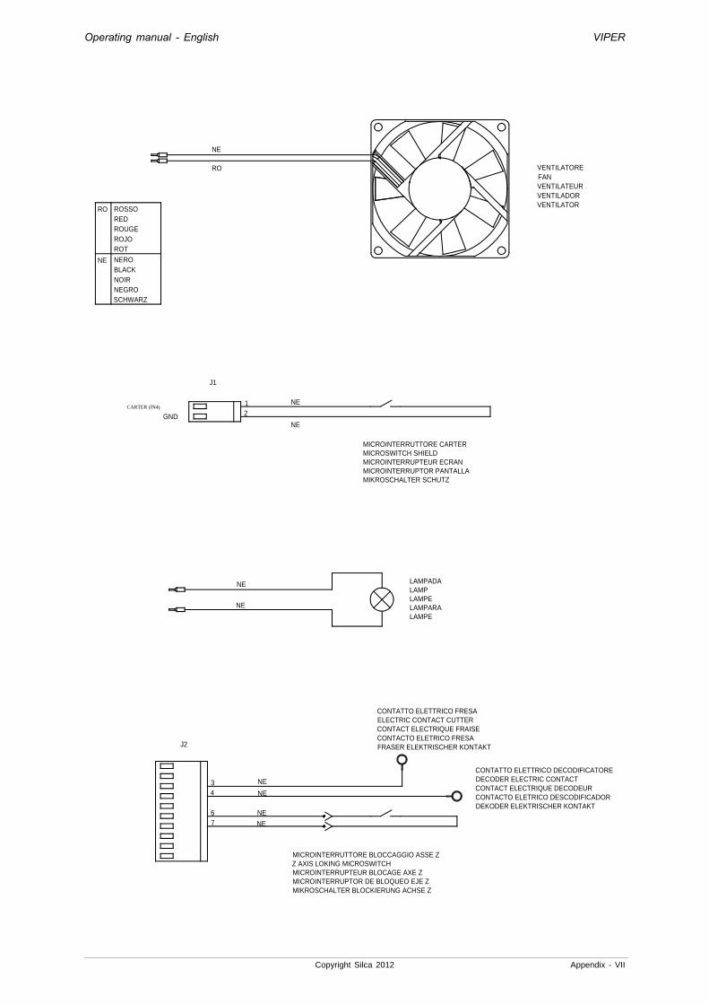
Operating manual - English VIPER
Copyright Silca 2012 Appendix - VII
12
ROSSOREDROUGEROJOROT
NEROBLACKNOIRNEGROSCHWARZ
NE
RO
GND
VENTILATOREFANVENTILATEURVENTILADORVENTILATOR
RO
MICROINTERRUTTORE CARTERMICROSWITCH SHIELDMICROINTERRUPTEUR ECRANMICROINTERRUPTOR PANTALLAMIKROSCHALTER SCHUTZ
CARTER (IN4)
NE
NE
LAMPADALAMPLAMPELAMPARALAMPE
J1
NE
NE
NE
34
MICROINTERRUTTORE BLOCCAGGIO ASSE ZZ AXIS LOKING MICROSWITCHMICROINTERRUPTEUR BLOCAGE AXE ZMICROINTERRUPTOR DE BLOQUEO EJE ZMIKROSCHALTER BLOCKIERUNG ACHSE Z
NE
J2
NE
76
NE
NE
CONTATTO ELETTRICO FRESAELECTRIC CONTACT CUTTERCONTACT ELECTRIQUE FRAISE CONTACTO ELETRICO FRESAFRASER ELEKTRISCHER KONTAKT
CONTATTO ELETTRICO DECODIFICATOREDECODER ELECTRIC CONTACT CONTACT ELECTRIQUE DECODEURCONTACTO ELETRICO DESCODIFICADOR DEKODER ELEKTRISCHER KONTAKT

Operating manual - English VIPER
VIII - Appendix Copyright Silca 2012

VITTORIO VENETO 24/03/2011 CE DECLARATION OF MACHINE COMPLIANCE SILCA S.p.A. - VIA PODGORA 20 ( Z.I.) 31029 VITTORIO VENETO (TV) - (ITALY) TEL. 0438 9136 - FAX. 0438 913800 Declares under its own responsibility that the Key-cutting machine model VIPER complies with the requirements of the following European Directives: European Union DIRECTIVE 2006/42/CE (Machines) and with the EN 292/1 – EN 292/2 Standards European Union DIRECTIVE 2004/108/CE (Electromagnetic Compatibility) and with the EN 55022 : 1998 + A1 : 2000 - EN 55024 : 1998 EN 61000 – 3 – 2 : 2000 EN 61000 - 3 – 3 :1995 + A1 : 2001 Standards European Union DIRECTIVE 2006/95/CE (Low Voltage) | 06 | and with the EN 60204-1 ( sections 20.2 – 20.3 – 20.4 ) Standards Claudio Tomasella of the Silca S.p.A. Research & Development Division is authorized to create a Technical File. General Manager Basic Production Center
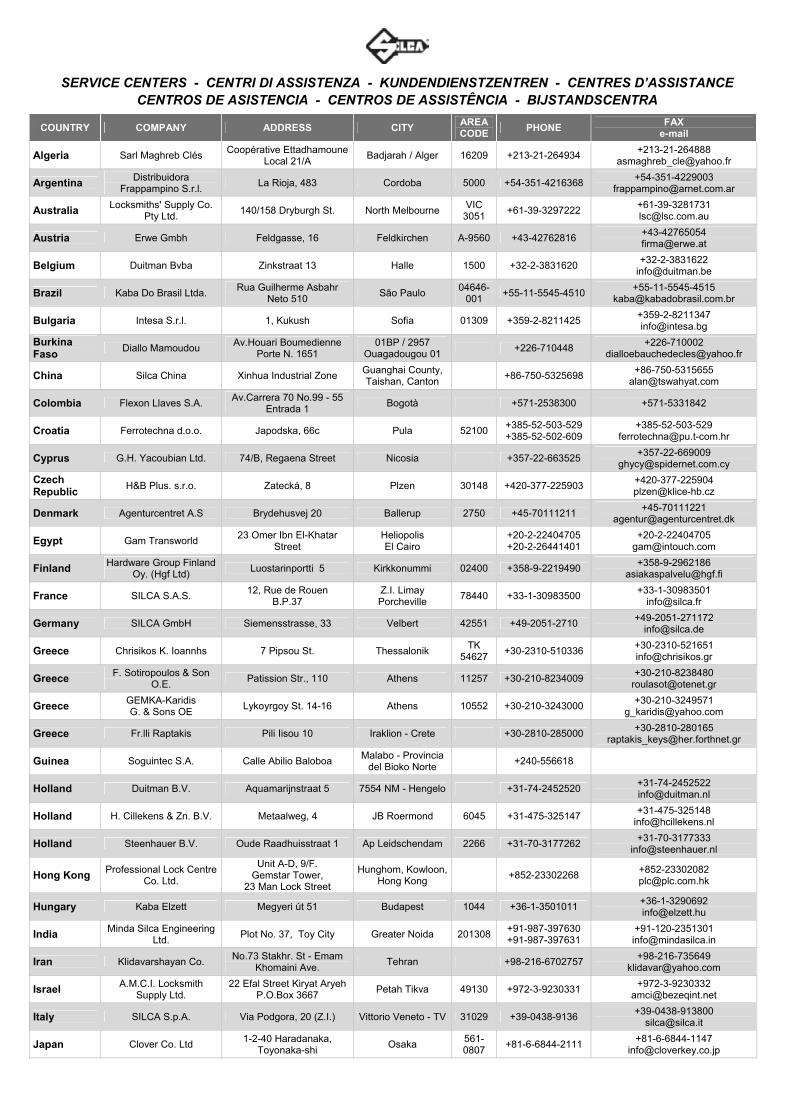
SERVICE CENTERS - CENTRI DI ASSISTENZA - KUNDENDIENSTZENTREN - CENTRES D’ASSISTANCE
CENTROS DE ASISTENCIA - CENTROS DE ASSISTÊNCIA - BIJSTANDSCENTRA
COUNTRY COMPANY ADDRESS CITY AREA CODE
PHONE FAX
Algeria Sarl Maghreb Clés Coopérative Ettadhamoune
Local 21/A Badjarah / Alger 16209 +213-21-264934
+213-21-264888 [email protected]
Argentina Distribuidora Frappampino S.r.l.
La Rioja, 483 Cordoba 5000 +54-351-4216368 +54-351-4229003
Australia Locksmiths' Supply Co. Pty Ltd.
140/158 Dryburgh St. North Melbourne VIC
3051 +61-39-3297222
+61-39-3281731 [email protected]
Austria Erwe Gmbh Feldgasse, 16 Feldkirchen A-9560 +43-42762816 +43-42765054 [email protected]
Belgium Duitman Bvba Zinkstraat 13 Halle 1500 +32-2-3831620 +32-2-3831622
Brazil Kaba Do Brasil Ltda. Rua Guilherme Asbahr
Neto 510 São Paulo
04646-001
+55-11-5545-4510 +55-11-5545-4515
Bulgaria Intesa S.r.l. 1, Kukush Sofia 01309 +359-2-8211425 +359-2-8211347 [email protected]
Burkina Faso
Diallo Mamoudou Av.Houari Boumedienne
Porte N. 1651 01BP / 2957
Ouagadougou 01 +226-710448
+226-710002 [email protected]
China Silca China Xinhua Industrial Zone Guanghai County, Taishan, Canton
+86-750-5325698 +86-750-5315655
Colombia Flexon Llaves S.A. Av.Carrera 70 No.99 - 55
Entrada 1 Bogotà +571-2538300 +571-5331842
Croatia Ferrotechna d.o.o. Japodska, 66c Pula 52100 +385-52-503-529 +385-52-502-609
+385-52-503-529 [email protected]
Cyprus G.H. Yacoubian Ltd. 74/B, Regaena Street Nicosia +357-22-663525 +357-22-669009
Czech Republic
H&B Plus. s.r.o. Zatecká, 8 Plzen 30148 +420-377-225903 +420-377-225904 [email protected]
Denmark Agenturcentret A.S Brydehusvej 20 Ballerup 2750 +45-70111211 +45-70111221
Egypt Gam Transworld 23 Omer Ibn El-Khatar
Street Heliopolis El Cairo
+20-2-22404705 +20-2-26441401
+20-2-22404705 [email protected]
Finland Hardware Group Finland Oy. (Hgf Ltd)
Luostarinportti 5 Kirkkonummi 02400 +358-9-2219490 +358-9-2962186
France SILCA S.A.S. 12, Rue de Rouen
B.P.37 Z.I. Limay Porcheville
78440 +33-1-30983500 +33-1-30983501
Germany SILCA GmbH Siemensstrasse, 33 Velbert 42551 +49-2051-2710 +49-2051-271172
Greece Chrisikos K. Ioannhs 7 Pipsou St. Thessalonik TK
54627 +30-2310-510336
+30-2310-521651 [email protected]
Greece F. Sotiropoulos & Son O.E.
Patission Str., 110 Athens 11257 +30-210-8234009 +30-210-8238480
Greece GEMKA-Karidis G. & Sons OE
Lykoyrgoy St. 14-16 Athens 10552 +30-210-3243000 +30-210-3249571
Greece Fr.lli Raptakis Pili Iisou 10 Iraklion - Crete +30-2810-285000 +30-2810-280165
Guinea Soguintec S.A. Calle Abilio Baloboa Malabo - Provincia
del Bioko Norte +240-556618
Holland Duitman B.V. Aquamarijnstraat 5 7554 NM - Hengelo +31-74-2452520 +31-74-2452522 [email protected]
Holland H. Cillekens & Zn. B.V. Metaalweg, 4 JB Roermond 6045 +31-475-325147 +31-475-325148
Holland Steenhauer B.V. Oude Raadhuisstraat 1 Ap Leidschendam 2266 +31-70-3177262 +31-70-3177333
Hong Kong Professional Lock Centre Co. Ltd.
Unit A-D, 9/F. Gemstar Tower,
23 Man Lock Street
Hunghom, Kowloon, Hong Kong
+852-23302268 +852-23302082 [email protected]
Hungary Kaba Elzett Megyeri út 51 Budapest 1044 +36-1-3501011 +36-1-3290692 [email protected]
India Minda Silca Engineering Ltd.
Plot No. 37, Toy City Greater Noida 201308 +91-987-397630 +91-987-397631
+91-120-2351301 [email protected]
Iran Klidavarshayan Co. No.73 Stakhr. St - Emam
Khomaini Ave. Tehran +98-216-6702757
+98-216-735649 [email protected]
Israel A.M.C.I. Locksmith Supply Ltd.
22 Efal Street Kiryat Aryeh P.O.Box 3667
Petah Tikva 49130 +972-3-9230331 +972-3-9230332
Italy SILCA S.p.A. Via Podgora, 20 (Z.I.) Vittorio Veneto - TV 31029 +39-0438-9136 +39-0438-913800
Japan Clover Co. Ltd 1-2-40 Haradanaka,
Toyonaka-shi Osaka
561-0807
+81-6-6844-2111 +81-6-6844-1147

COUNTRY COMPANY ADDRESS CITY AREA CODE
PHONE FAX
Kenya MPPS Ltd. P.O. Box 31347 Nairobi +254-20-6532913 +254-20-6533370
+254-20-6533369 [email protected]
Kuwait Hasawi & Sabano Co. For Gen.Trad.
P.O. Box 42105 Kuwait City 70652 +965-24832505 +965-2622778
Latvia Solo F Ltd. Salaspils 12 Riga 1057 +371-7278359 +371-7876901
Lebanon Mouawad Books & Stationary Sarl.
Mouawad Str. Mouawad Center, 60094 Jal el Dib
Beyrouth +961-4-711202 +961-4-11206 [email protected]
Macedonia Panevski & Sinovi Llidenska , 11 Kumanovo 1300 +389-31-411545 +389-31-412411
Malta Unimark Ltd. 32, Zerafa Str. Hmr 03 Marsa +356-21-231540 +356-241319
Mexico Corporacion Cerrajera Alba Sa De Cv
Circuito Gustavo BAZ, 16 Atizapan de Zaragoza
Messico D.F. 52966 +52-55-53667200 +52-55-53667291
Mozambique Davel Importacao Comercio e Servicos
Rua Do Carmo NR.54 - 3° Solat
Coimbra 3000 +351 239833858 +351 914506747
New Zealand
Baber LSC Limited Unit 5, 6 Argus Place
Auckland Glenfield 1310 +649-444-5117
+649-444-5119 [email protected]
Nigeria Chilex Security Products Ltd.
12, Olowu Street P.O. Box 5153
Ikeja - Lagos +234-1-4965005 +234-1-4965005
Norway Prodib Ab Montorgat 16 Eskilstuna 632 29 +46-16-168000 +46-16-145590
Poland Dar-Mar ul. Napoleona, 17 Kobylka 05-230 +48-22-7710118 +48-22-7710118
Poland Z.P.U.H. Expres Wojcieck Kowalczyk
32-447 Siepraw 795 Siepraw +48-1227-46365 +48-1227-46365
Portugal Casa Das Chaves Da Falagueira Ltda
Estrada Da Falagueira 5B Amadora 2701 +351-214936430 +351-214912403
Portugal Luso Chav' Av. Rodrigues de Freitas,
199-A Porto
4000-303
+351-22-5104702 +351-22-5361248 [email protected]
Romania M&C Business S.r.l. 36, Badea Cartan Street
2nd District Bucharest 20064 +40-213118602
+40-212120155 [email protected]
Russia Strazh 16/2, pt. Komsomolskiy Moscow 119021 +7 495 7083440 +7-495-7083292
Russia O.O.O. Peter Key Mihaylovsky Pereulok, 7b Saint Petersburg 198095 +7-812-2520241 +7-812-2523885
Saudi Arabia
Fahd Omar Bamashmous Est.
P.O. Box 20919 Jeddah 21465 +966-2-6422588 +966-2-6447238
Serbia Silkon D.O.O. 29, Novembra 70 Belgrade 11000 +381-11-2080200 +381-11-3290017
Singapore Silca Soxxi Pte. Ltd. 21 Toh Guan Rd. East
#01-12 Toh Guan Centre Singapore 608609 +65-6316-8100
+65-6316-4470 [email protected]
Slovakia H&B Slovakia s.r.o. Ovsistske Nam. 1 Bratislava 85104 +421-2-6252-0032 +421-2-6252-0033
+421-2-6252-0034 [email protected]
South Africa Sanlic International (Pty) Ltd.
46, Hulbert Street New Centre
Johannesburg +27-11-4939717 +27-11-6831312
Spain Silca Key Systems S.A. C/Santander 73/A Barcelona 08020 +34-93-4981400 +34-93-2788004 [email protected]
Sweden Prodib Ab Montorgat 16 Eskilstuna 632 29 +46-16-168000 +46-16-145590
Switzerland Robert Rieffel Ag Widenholzstrasse 8 Wallisellen 8304 +41-44-8773333 +41-44-8773322 [email protected]
Syria Muheiddin Arabi Katbi P.O. Box 1322 Damascus +963-11-2212407 +963-11-2224588
+963-11-2224588 +963-11-3737001
Taiwan Global Tecspro Ltd. 11F-2 N.42-2 Lian Sheng
St. Jhongho City
Taipei +886-2-22494028
+886-2-22425735 [email protected]
Turkey Kadiköy Anahtar San.Ve.Tic.Ltd.Sti.
Osmanaja Mah.Nüzhet Efendi Sk.No.56
Kadiköy - Istanbul +90-216-4145254 +90-216-3475488
U.A.E. Sabano Trading Co.Llc P.O. Box 32075 Dubai +971-4-2682400 +971-4-2622778
Ukraine Service-Centre Kopir Segedskaya 12 Odessa 65009 +38-487-433196 +38-487-190777
United Kingdom
SILCA Ltd. 6 Lloyds Court Manor Royal
Crawley RH10 9QU
+44-1293-531134 +44-1293-531108
U.S.A. Kaba Ilco Corp. 400 Jeffreys Road,
P.O. Box 2627 Rocky Mount
NC 27804 +1-252-446-3321
+1-252-446-4702 [email protected]
Venezuela La Casa del Cerrajero C.A.
Av. Principal de Maripérez Caracas +58-212-793-0083 +58-212-781-8692
Yemen Sabano Trading Co.Llc P.O. Box 32075 Dubai U.A.E. +971-4-2682400 +971-4-2622778

SILCA S.p.A. Via Podgora, 20 (Z.I.)
31029 VITTORIO VENETO (TV) Tel. 0438 9136 Fax 0438 913800
E-mail: [email protected] www.silca.biz
Members of the Kaba Group


