H2020 – FOF – 09 – 2015 Innovation Action Smart integrated immersive and symbiotic human-robot collaboration system controlled by Internet of Things based dynamic manufacturing processes with emphasis on worker safety This project has received funding from the European Union’s Horizon 2020 research and innovation programme under grant agreement No 680734 D4.5 User Handbook Report Identifier: D4.5 Work-package, Task: WP4, Task 4.2 Status – Version: 1.0 Distribution Security: PU Deliverable Type: R Editor: Venelin Arnaudov (PROS) Contributors: Tuncher Shefkaev (PROS) Reviewers: TUM, ED Quality Reviewer: ED Keywords: Project website: www.horse-project.eu
Transcript
H2020 – FOF – 09 – 2015
Innovation Action
Smart integrated immersive and symbiotic human-robot collaboration system controlled by Internet of Things based dynamic manufacturing processes with
emphasis on worker safety
This project has received funding from the European Union’s Horizon 2020 research and innovation programme under grant agreement No 680734
D4.5 User Handbook
Report Identifier: D4.5
Work-package, Task: WP4, Task 4.2 Status – Version: 1.0
Use of any knowledge, information or data contained in this document shall be at the user's sole risk. Neither the HORSE Consortium nor any of its members, their officers, employees or agents accept shall be liable or responsible, in negligence or otherwise, for any loss, damage or expense whatever sustained by any person as a result of the use, in any manner or form, of any knowledge, information or data contained in this document, or due to any inaccuracy, omission or error therein contained.
The European Commission shall not in any way be liable or responsible for the use of any such knowledge, information or data, or of the consequences thereof.
This document does not represent the opinion of the European Union and the European Union is not responsible for any use that might be made of it.
This document contains information that is protected by copyright. All Rights Reserved. No part of this work covered by copyright hereon may be reproduced or used in any form or by any means without the permission of the copyright holders.
2.2.1 Short Description ....................................................................................................................................... 13
2.2.2 System Requirements .............................................................................................................................. 15
2.2.3 Legal Status ................................................................................................................................................... 15
2.3.1 Short Description ....................................................................................................................................... 16
2.3.2 System Requirements .............................................................................................................................. 16
2.3.3 Legal Status ................................................................................................................................................... 16
2.4.1 Short Description ....................................................................................................................................... 16
2.4.2 System Requirements .............................................................................................................................. 17
2.4.3 Legal Status ................................................................................................................................................... 20
2.5.1 Short Description ....................................................................................................................................... 23
2.5.2 System Requirements .............................................................................................................................. 23
2.5.2.1 Design and development requirements ...................................................................................... 23
2.5.3 Legal Status ................................................................................................................................................... 26
2.6.1 Short Description ....................................................................................................................................... 26
2.6.2 System Requirements .............................................................................................................................. 26
2.6.3 Legal Status ................................................................................................................................................... 26
2.7.1 Short Description ....................................................................................................................................... 27
2.7.2 System Requirements .............................................................................................................................. 27
2.7.3 Legal Status ................................................................................................................................................... 28
2.7.5 Administration and support .................................................................................................................. 28
2.8 LOCAL SAFETY GUARD............................................................................................................................................. 28
2.8.1 Short Description ....................................................................................................................................... 28
2.8.2 System Requirements .............................................................................................................................. 28
2.8.3 Legal Status ................................................................................................................................................... 29
2.8.5 Administration and support .................................................................................................................. 29
2.9 HUMAN DETECTION AND TRACKING .................................................................................................................... 29
2.9.1 Short Description ....................................................................................................................................... 29
2.9.2 System Requirements .............................................................................................................................. 30
2.9.3 Legal Status ................................................................................................................................................... 30
2.10.1 Short Description ....................................................................................................................................... 31
2.10.2 System Requirements .............................................................................................................................. 31
2.10.3 Legal Status ................................................................................................................................................... 31
2.10.5 Administration and support .................................................................................................................. 31
2.11.1 Short Description ....................................................................................................................................... 31
2.11.2 System Requirements .............................................................................................................................. 31
D4.5 User Handbook
Page 5 of 55
2.11.3 Legal Status ................................................................................................................................................... 31
2.11.5 Administration and support .................................................................................................................. 32
2.12.1 Short Description ....................................................................................................................................... 32
2.12.2 System Requirements .............................................................................................................................. 33
2.12.3 Legal Status ................................................................................................................................................... 33
2.12.5 Administration and support .................................................................................................................. 33
2.13 KUKA SUNRISE ........................................................................................................................................................ 33
2.13.1 Short Description ....................................................................................................................................... 33
2.13.2 System Requirements .............................................................................................................................. 34
2.13.3 Legal Status ................................................................................................................................................... 34
2.13.5 Administration and support .................................................................................................................. 35
2.14.1 Short Description ....................................................................................................................................... 36
2.14.2 System Requirements .............................................................................................................................. 37
2.14.3 Legal status ................................................................................................................................................... 37
2.14.5 Administration and support .................................................................................................................. 37
APPENDIX A ............................................................................................................................................................ 40
4 APPENDIX B .................................................................................................................................................. 53
D4.5 User Handbook
Page 6 of 55
List of Figures
FIGURE 1: DEPLOYMENT EXAMPLE ...................................................................................................................... 11
FIGURE 2: HORSE EXEC GLOBAL DEPLOYMENT ..................................................................................................... 12
FIGURE 3: HORSE EXEC LOCAL DEPLOYMENT ....................................................................................................... 13
FIGURE 7: SHARED, CONTAINER-MANAGED PROCESS ENGINE.................................................................................. 18
FIGURE 8: SITUATION AWARENESS WITHIN HORSE FRAMEWORK ............................................................................. 23
FIGURE 9: USE CASE SCENE ................................................................................................................................. 24
FIGURE 20: TEST WEB CLIENT ............................................................................................................................. 51
FIGURE 21: CONFIGURATION OF THE HORSE BOS ADAPTER - COORDINATOR............................................................ 54
TNO Nederlandse Organisatie voor Toegepast Natuurwetenschappelijk Onderzoek (Netherlands Organisation for Applied Scientific Research)
TUE Technical University of Eindhoven
TUM Technical University of Munich
URDF Unified Robot Description Format
(*) This HORSE deliverable is not public. A copy could be granted upon the discretion of the project’s Coordination Board.
D4.5 User Handbook
Page 9 of 55
Executive Summary
This deliverable provides a guideline for installation of the HORSE components and supporting infrastructure. The most of these components are developed as extensions or on top of existing products and implement state of the art technologies. The contact data of the component developers or product support is provided as a reference for further information and assistance.
D4.5 User Handbook
Page 10 of 55
1 Introduction
1.1 Objectives
The key objective of the HORSE project is to inform and enable SMEs to adopt robotic technologies and collaborative solutions. For this purpose, the HORSE consortium designed and implemented a flexible framework (a collection of components) that can be easily tailored to the needs of the entrepreneurs.
The resulted distributed solution is based on the state of the art technologies and products in the domain of Industry 4.0, Internet of Things robotics and business processes. This document should help the prospective users to evaluate the cost of procuring of equipment and estimation of the efforts for setup and maintenance of the desired constellation of HORSE components.
1.2 Structure
The key part of the document is the section containing description of the installation specifics for each component and the requirements towards the IT infrastructure and equipment (machines, sensors. Some more detailed setup and operation instructions have been provided as appendices.
D4.5 User Handbook
Page 11 of 55
2 HORSE Components
2.1 Overview
This chapter provides a short introduction of the modules implementing the building blocks identified in the HORSE system design (HORSE Deliverable 2.21). The presented modules should be configured and customised in order to be able to realise the specific scenarios of the end users.
Figure 1 the two major types of functional domains of grouping the HORSE modules.
Figure 1: Deployment Example
Each deployment of the HORSE framework should feature one Global Execution domain, comprising of the components responsible for the global process management and global situation awareness. The detailed view of the modules in this group is given in Figure 2.
1 A public version of the deliverable is available at http://www.horse-project.eu/Publications
D4.5 User Handbook
Page 12 of 55
Figure 2: HORSE Exec Global Deployment
The components interacting with the agents (human and automated), local equipment and sensors could be deployed in one or more groups in the relevant work cells. Figure 3 gives a more detailed view of a typical deployment of the Local Execution functional domain.
The main interface for communication between the components is the exchange of messages over the HORSE Messaging Middleware. These connections are marked with “HM”.
The HORSE Broker (one for each functional domain) is responsible for forwarding the messages to the designated recipients. The communication between the domains is realised through the HORSE Dispatcher (one for the entire system) who is mediating between the brokers.
Another protocol used for communication between the components dealing with robots and other time sensitive equipment is ROS. The conversion of the messages exchanged over the HORSE Messaging Middleware and the ROS messages is done by the HORSE-ROS Bridge.
The connection to the local DB server (usually residing in Global Execution domain) is done over JDBC protocol. For a better readability of Figure 3, the JDBC connections of the single components are not displayed. Instead, there is one collective connection between the Local Execution domain and the DB server.
D4.5 User Handbook
Page 13 of 55
Figure 3: HORSE Exec Local Deployment
The next sections provide more details on the installation and configuration specifics of each HORSE module.
2.2 Messaging Middleware
2.2.1 Short Description
The HORSE Messaging Middleware is responsible for communication between the HORSE components. It consists of:
• Broker, deployed in each functional domain and enabling the com • Dispatcher, one instance, mediating between the brokers • Client specification and a reference implementation • Agent Manager, providing information about the connection status of the messaging
clients • Lifecycle management of the connections to the agents • Format of the JSON based message
D4.5 User Handbook
Page 14 of 55
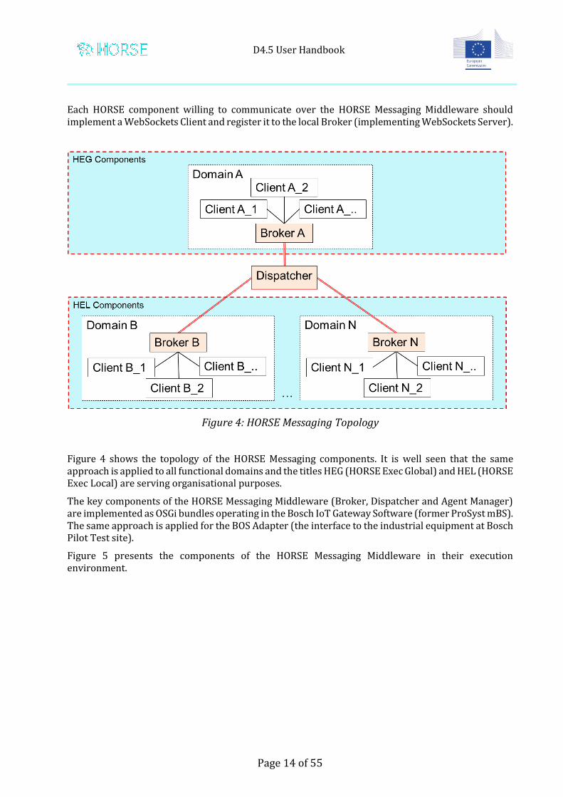
Each HORSE component willing to communicate over the HORSE Messaging Middleware should implement a WebSockets Client and register it to the local Broker (implementing WebSockets Server).
Figure 4: HORSE Messaging Topology
Figure 4 shows the topology of the HORSE Messaging components. It is well seen that the same approach is applied to all functional domains and the titles HEG (HORSE Exec Global) and HEL (HORSE Exec Local) are serving organisational purposes.
The key components of the HORSE Messaging Middleware (Broker, Dispatcher and Agent Manager) are implemented as OSGi bundles operating in the Bosch IoT Gateway Software (former ProSyst mBS). The same approach is applied for the BOS Adapter (the interface to the industrial equipment at Bosch Pilot Test site).
Figure 5 presents the components of the HORSE Messaging Middleware in their execution environment.
D4.5 User Handbook
Page 15 of 55
Figure 5: Execution Environment for PRO modules
The HORSE Messaging Middleware has been described in HORSE deliverables D3.11 Final Version of HORSE Cross-Domain Messaging and D3.13 Final Version of the Middleware for HORSE Execution Domains.
2.2.2 System Requirements
CPU: x86, ARM
OS: Windows, Linux, MacOS
RAM: at least 4 GB
Disk Space: at least 2 GB for storing the log files
Java VM: Oracle 1.8, Open JDK 1.8
DB: postgreSQL (local or remote)
OSGi implementation: Bosch IoT Gateway Software (former ProSyst mBS), version 8.1.4 or higher
2.2.3 Legal Status
The HORSE Messaging Middleware components and the underlying Bosch IoT Gateway Software are provided free of charge to the consortium members and Open Calls partners for the duration of the project. For a further use, please contact the vendor Bosch Software Innovations GmbH.
D4.5 User Handbook
Page 16 of 55
2.2.4 Installation Guide
See Appendix A.
2.2.5 Administration and support
• See the usage guide in Appendix A • For further assistance contact:
The HORSE-ROS Bridge is a component that allows the communication between native ROS nodes (the Open-Source framework "Robot Operating System") and nodes using the HORSE middleware. It enables the middleware clients to use the full ROS functionalities available to native ROS nodes. In order to allow the forwarding of HORSE events originating at native ROS nodes to middleware nodes, it offers a ROS service interface to forward arbitrarily complex messages.
2.3.2 System Requirements
The HORSE-ROS Bridge requires Ubuntu Linux 16.04 with the ROS Kinetic framework.
2.3.3 Legal Status
The HORSE-ROS Bridge is distributed under the BSD license.
2.3.4 Installation Guide
The software and the installation guidelines are available at the HORSE website, under the menu “About HORSE -> Publications”.
The HORSE Design Global and the Global Execution modules of HORSE Exec Global of HORSE Software Architecture are the so called “Manufacturing Process Management System” (MPMS), the information system components which enable the design and execution of a manufacturing process which contains two or more tasks. In this Chapter we describe the technical details of MPMS.
The MPMS is the collection of subsystems responsible to orchestrate the tasks of agents in the manufacturing processes. Orchestration is dependent on the design of the processes and agents. The
MPMS includes the functionality to design processes and describe agents, and execute the processes by assigning activities to agents. It is built on traditional Business Process Management Systems (BPMS), with adaptations to fit the manufacturing domain. A Process Modeller is available for designing processes and a Process Engine undertakes the enactment of those.
MPMS communicates, through the Middleware, with the Local modules which eventually trigger the agents.
The management of the high level tasks is handled by the MPMS. Its user interface is executed by a web server like WildFly or Apache.
2.4.2 System Requirements
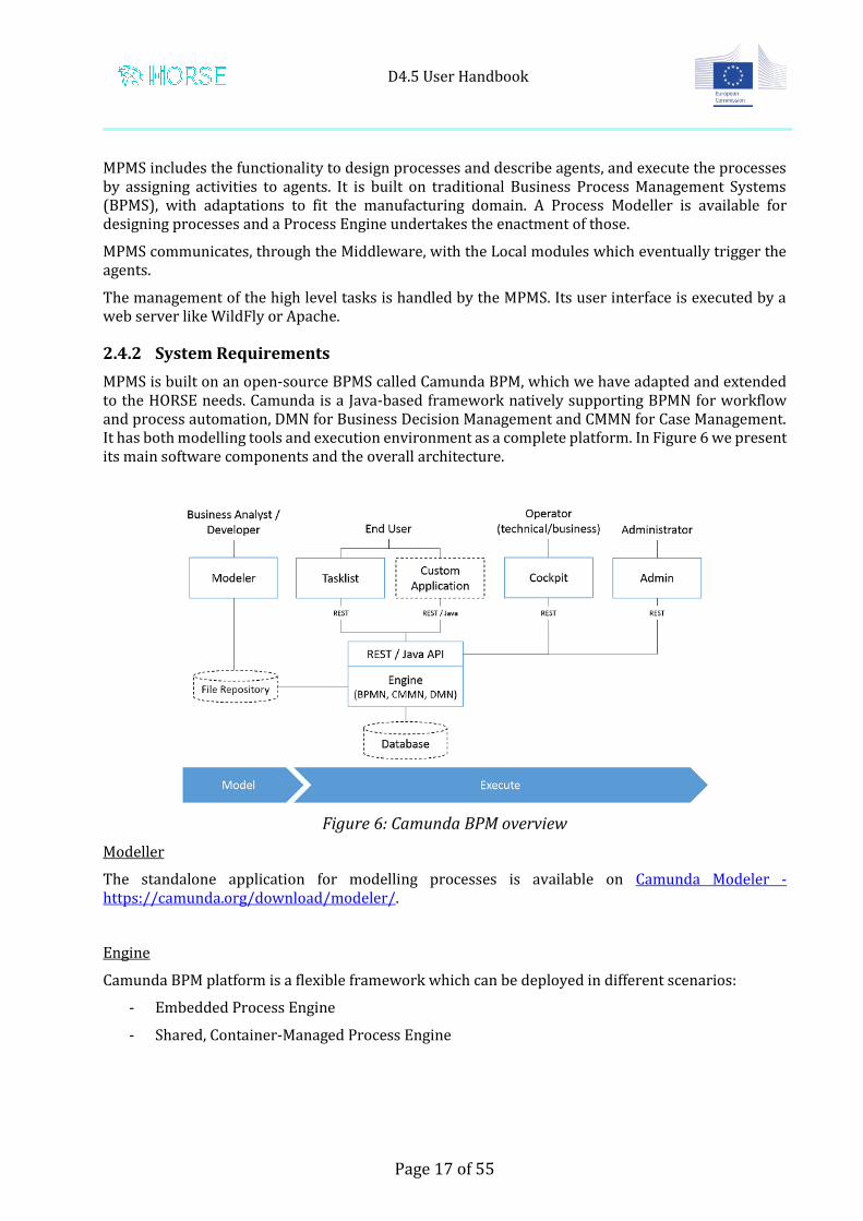
MPMS is built on an open-source BPMS called Camunda BPM, which we have adapted and extended to the HORSE needs. Camunda is a Java-based framework natively supporting BPMN for workflow and process automation, DMN for Business Decision Management and CMMN for Case Management. It has both modelling tools and execution environment as a complete platform. In Figure 6 we present its main software components and the overall architecture.
Figure 6: Camunda BPM overview
Modeller
The standalone application for modelling processes is available on Camunda Modeler - https://camunda.org/download/modeler/.
Engine
Camunda BPM platform is a flexible framework which can be deployed in different scenarios:
- Embedded Process Engine
- Shared, Container-Managed Process Engine
D4.5 User Handbook
Page 18 of 55
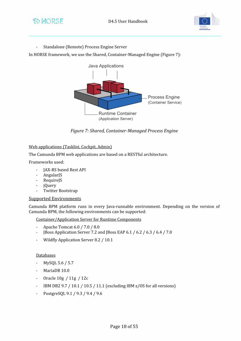
- Standalone (Remote) Process Engine Server
In HORSE framework, we use the Shared, Container-Managed Engine (Figure 7):
Figure 7: Shared, Container-Managed Process Engine
Web applications (Tasklist, Cockpit, Admin)
The Camunda BPM web applications are based on a RESTful architecture.
Frameworks used:
- JAX-RS based Rest API - AngularJS - RequireJS - jQuery - Twitter Bootstrap
Supported Environments
Camunda BPM platform runs in every Java-runnable environment. Depending on the version of Camunda BPM, the following environments can be supported:
Container/Application Server for Runtime Components
- IBM DB2 9.7 / 10.1 / 10.5 / 11.1 (excluding IBM z/OS for all versions)
- PostgreSQL 9.1 / 9.3 / 9.4 / 9.6
D4.5 User Handbook
Page 19 of 55
- Microsoft SQL Server 2008 R2 / 2012 / 2014
- H2 1.4
Web Browser
- Google Chrome latest
- Mozilla Firefox latest
- Internet Explorer 9 / 10 / 11
Java
- Java 6 / 7
- Java 8 (if supported by your application server/container)
Java Runtime
- Sun/Oracle Hot Spot 6 / 7 / 8
- IBM® J9 virtual machine (JVM) 6 / 7 / 8
- OpenJDK 7 / 8
- Oracle JRockit 6 - R28.2.7
Camunda Modeler
- Windows 7 / 10
- Mac OS X 10.11
- Linux
Camunda BPM is available as a full distribution, available on Camunda Download - https://camunda.org/download/.
It bundles:
- Process Engine configured as shared process engine - Runtime Web Applications (Tasklist, Cockpit, Admin)
- Rest API
- Container / Application Server itself
For HORSE we use Camunda BPM 7.7.0 – WildFly 10 Distribution, using all above components.
TUE implemented the application processes that interact with the engine.
D4.5 User Handbook
Page 20 of 55
For registering the MPMS as a Websocket Agent in the Message Bus, we use Java API for WebSocket JSR 356, which defines a standard API for creating websocket applications. We implement a @ClientEndpoint POJO, which is responsible to open/close a websocket connection (we only need the IP address and the port number of the Message Bus server to register MPMS as a client node) and send/receive messages.
For DB integration, in the default configuration of the Camunda BPM distribution, the database schema and all required tables are automatically created in an H2 database when the engine starts up for the first time. These are internal engine data.
For “business/application” data, like for example the Product DB or Agent Def. DB., we use a PostgreSQL JDBC driver to connect to the PostgreSQL DB Server. We implement a “horse” DB, with all the right datatables.
PC Requirements
For deploying MPMS in a local desktop PC, not any special requirements are needed. A powerful processor, a lot of RAM memory and a decent graphics card is sufficient. The following specs are recommended:
The Camunda Community Platform is licensed under the Apache License 2.0 - http://www.apache.org/licenses/LICENSE-2.0.html. Third-party libraries or application servers included are distributed under their respective licenses. We present below a list of the required dependencies we use in MPMS (to provide core functionality). Full list including optional dependencies can be found on Camunda - Third party libraries - https://docs.camunda.org/manual/7.7/introduction/third-party-libraries/.
Third party libraries
The process engine depends on the following third-party libraries:
MyBatis mapping framework, (Apache License 2.0) for object-relational mapping
Joda Time, (Apache License 2.0) for parsing date formats
Java Uuid Generator (JUG), (Apache License 2.0) Id Generator
SLF4J, (MIT License) Logging Façade
Apache Commons Email, (Apache License 2.0) for mail task support
Groovy, (Apache License 2.0) for groovy script task support
D4.5 User Handbook
Page 21 of 55
The REST API depends on the following third-party libraries: Jackson JAX-RS, (Apache License 2.0) provider for JSON content type Apache Commons FileUpload, (Apache License 2.0)
Camunda Spin depends on the following third-party libraries:
Jackson Json, (Apache License 2.0) for Json Dataformat Support
Camunda Connect depends on the following third-party libraries: Apache Http Components, (Apache License 2.0) for REST and SOAP support
The Camunda Webapps (Cockpit, Tasklist, Admin) include the following third-party libraries: AngularJS, (MIT License) AngularUI, (MIT License) bpmn-js, (bpmn-js Custom license) domReady, (MIT License or new BSD License) heatmap.js, (MIT License) Placeholder.js, (MIT License) prism.js, (MIT License) jQuery, (MIT License) jQuery UI, (MIT License) RequireJS, (MIT License) Snap.svg, (Apache License 2.0) Twitter Bootstrap, (Apache License 2.0) Mousetrap, (Apache License 2.0)
Most of these libraries are used in the Camunda commons UI library which is aimed at easing development of browser based user interfaces.
The Camunda Javascript SDK (including the Forms SDK) integrates with the following third-party libraries:
Regarding connection to DB server, PostgreSQL is released under the PostgreSQL License, a liberal Open Source license, similar to the BSD or MIT licenses.
D4.5 User Handbook
Page 22 of 55
2.4.4 Installation Guide
In short, installing MPMS includes the following steps:
Prerequisites
- Before downloading Camunda, make sure you have a JRE (Java Runtime Environment), or better, a JDK (Java Development Kit) installed. It is recommended to use Java 8 unless your container/application server does not support Java 8 (like JBoss Application Server 7). We installed Java 8 (after Java is installed, make sure that “JAVA_HOME” and/or “JRE_HOME” environment variables are set in your system).
- Apache Maven (optional, if not installed you can use embedded Maven e.g. inside Eclipse IDE)
Installation
- Download and install Camunda BPM 7.7.0 – WildFly 10 Distribution - Download PostgreSQL JDBC Driver for DB integration and put it on a specific folder of
Camunda distribution (details below) - Modify configuration file of Camunda engine (“standalone.xml” file of application server) - Run db scripts to create the “horse” DB and populate initial data (e.g. task definitions, agent
definitions, product info, etc.) - Configure the connection to the Message Bus server in the application process that is
implemented by TUE - Deploy the application process which is responsible to make the process models executable
by Camunda engine. This deployment will generate a .war file which needs to be dropped to the deployments folder of the application server (in the downloaded Camunda distribution).
- Run Camunda engine (“start” script file in the downloaded Camunda distribution - Create any users in Camunda Admin web application and give authorizations (optional) - Start a process in Camunda Tasklist web application - Monitor a process in Camunda Cockpit web application
The software, along with configuration scripts, deployment scripts and scripts for inserting data to the DB, as well as supporting documentation (like setting up users of Camunda, and detailed steps for installation) should be requested by TUE (dr.ir. Irene Vanderfeesten at [email protected]).
2.4.5 Administration and support
TUE is responsible for modelling manufacturing processes and making them executable by the MPMS. For more information please contact dr.ir. Irene Vanderfeesten at [email protected].
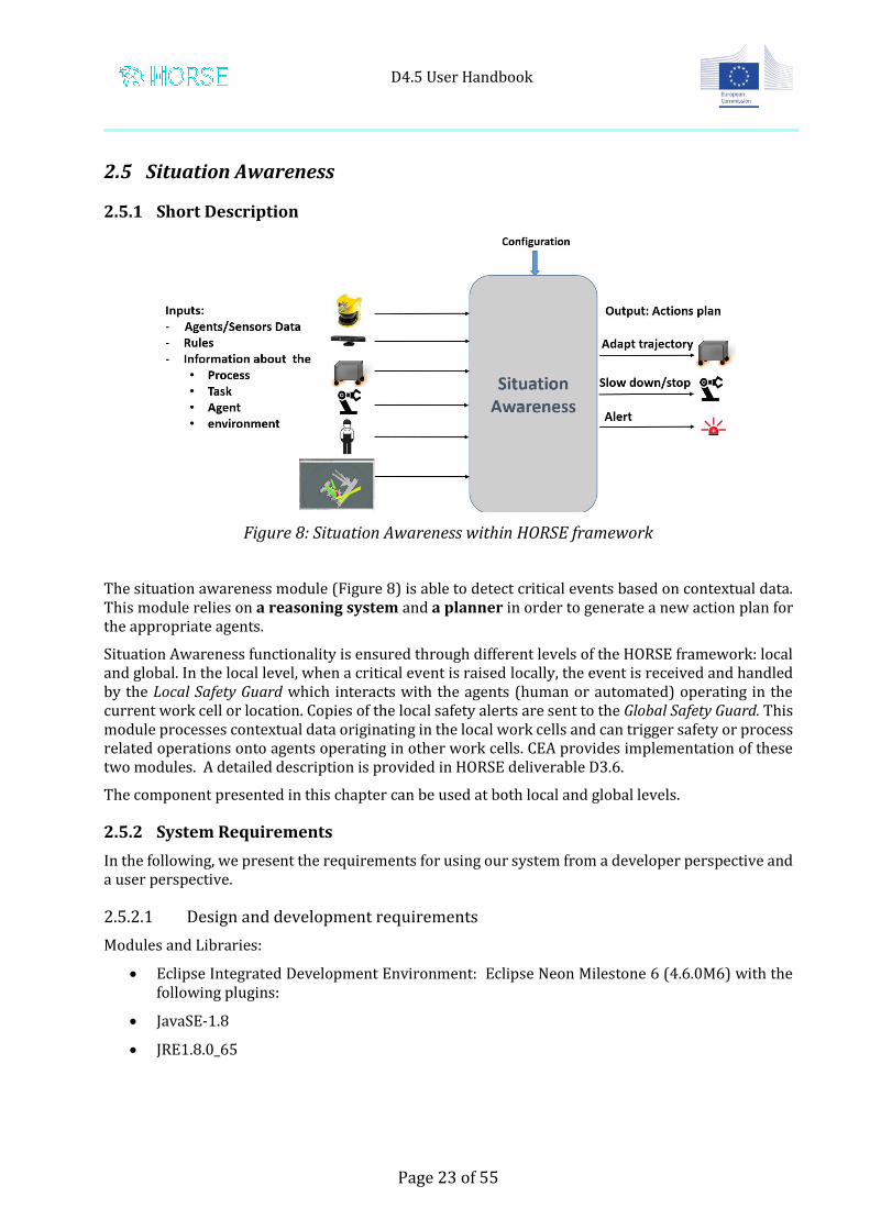
Figure 8: Situation Awareness within HORSE framework
The situation awareness module (Figure 8) is able to detect critical events based on contextual data. This module relies on a reasoning system and a planner in order to generate a new action plan for the appropriate agents.
Situation Awareness functionality is ensured through different levels of the HORSE framework: local and global. In the local level, when a critical event is raised locally, the event is received and handled by the Local Safety Guard which interacts with the agents (human or automated) operating in the current work cell or location. Copies of the local safety alerts are sent to the Global Safety Guard. This module processes contextual data originating in the local work cells and can trigger safety or process related operations onto agents operating in other work cells. CEA provides implementation of these two modules. A detailed description is provided in HORSE deliverable D3.6.
The component presented in this chapter can be used at both local and global levels.
2.5.2 System Requirements
In the following, we present the requirements for using our system from a developer perspective and a user perspective.
2.5.2.1 Design and development requirements
Modules and Libraries:
Eclipse Integrated Development Environment: Eclipse Neon Milestone 6 (4.6.0M6) with the following plugins:
JavaSE-1.8
JRE1.8.0_65
D4.5 User Handbook
Page 24 of 55
Maven
Message Pack and MessagePack-RPC libraries2
Protégé3 ontology editor
OWL files contain the ontologies including environment and task-specific information
SWRL files define rules for the reasoner
2.5.2.2 Configuration
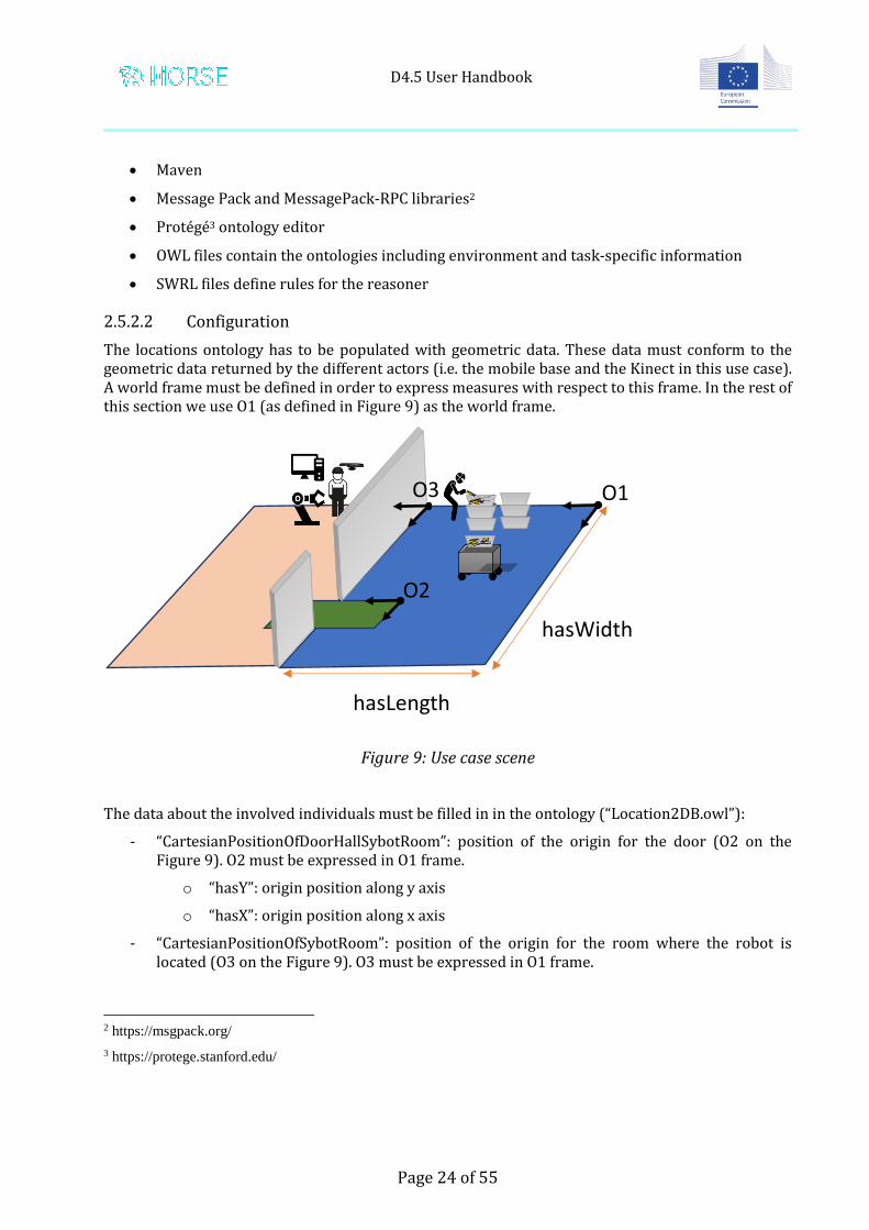
The locations ontology has to be populated with geometric data. These data must conform to the geometric data returned by the different actors (i.e. the mobile base and the Kinect in this use case). A world frame must be defined in order to express measures with respect to this frame. In the rest of this section we use O1 (as defined in Figure 9) as the world frame.
Figure 9: Use case scene
The data about the involved individuals must be filled in in the ontology (“Location2DB.owl”):
- “CartesianPositionOfDoorHallSybotRoom”: position of the origin for the door (O2 on the Figure 9). O2 must be expressed in O1 frame.
o “hasY”: origin position along y axis
o “hasX”: origin position along x axis
- “CartesianPositionOfSybotRoom”: position of the origin for the room where the robot is located (O3 on the Figure 9). O3 must be expressed in O1 frame.
2 https://msgpack.org/
3 https://protege.stanford.edu/
hasWidth
hasLength
O1
O2
O3
D4.5 User Handbook
Page 25 of 55
o “hasY”: origin position along y axis
o “hasX”: origin position along x axis
- “CartesianPositionOfOriginOfHall”: position of the origin of the room where the operator is located (O1 on the Figure 9): O2 must be expressed in O1 frame.
o “hasY”: origin position along y axis
o “hasX”: origin position along x axis
- “SpatialPositionOfDoorHallSybotRoom”: dimension of the area in green on the Figure 9 (it appears bigger than it is on the figure to make it visible)
o “hasWidth” as on the Figure 9
o “hasLength” as the Figure 9
- “SpatialPositionOfSybotRoom”: dimension of the room in pink on the Figure 9
o “hasWidth” as on the Figure 9
o “hasLength” as the Figure 9
- “SpatialPositionOfHall”: dimension of the room in blue on the Figure 9
o “hasWidth” as on the Figure 9
o “hasLength” as the Figure 9
A set of actions are pre-defined in the actions ontology (“Action2DB.owl”). If used robot differs from the one used for the use case, useful actions must be implemented for the robot (e.g. actions such as “MoveToPosition” or “Stop” for the mobile base). If unlisted actions are required, they must be referenced in the ontology and in the source code of the local situation awareness module.
Other parameters such as the distance thresholds that are used in the rules could be modified in the dedicated xml file. These parameters are:
- “GoalInTheSameRoom” and “GoalNextRoomNearSybot”: cartesian positions of the mobile base goals
- “Hidden”: cartesian position of the hidden position of the mobile base (safe position to reach when the agent and the mobile base are about to cross the door at the same time)
- “Home”: cartesian position for the mobile base (i.e. rest position)
- “isHowCloseToThresholds”: distance thresholds that raises different level of warnings
2.5.2.3 Runtime platform
The module is executed as a Java binary. Due to the platform independency of the Java applications, they could be deployed and operated in multiple operating systems. The module has been successfully tested on Windows, Linux and MAC-OS.
CPU – Intel x386 OS – Windows/Linux/MAC-OS
D4.5 User Handbook
Page 26 of 55
Memory – at least 4 GB Disk Space – at least 100 MB Java Runtime Environment 1.8+ Each device requires an implementation embedding MsgPack_RPC server
2.5.3 Legal Status
CEA is the exclusive owner of the intellectual properties on the components developed by its team. Upon a written request, CEA can offer a separate license agreement granting access rights on a non-exclusive basis, without the right to sublicense, and in case of software, in object code. The request for access rights may be made up to twelve months after the end of the project. It should specify the intended purpose.
CEA will transmit the specific conditions that will be applied for the specific access right. The rights will be granted subject to confidentiality obligations. Access Rights shall be granted on a royalty-free basis for the performance of the own work of a party under the Project for the duration of the Project. Access rights shall be granted against financial compensation if needed for exploitation of a party's own results in case of direct or indirect industrial or commercial exploitation.
2.5.4 Installation Guide
The safety guard equipment and software modules are to be requested by CEA. Their installation and configuration should be performed by a CEA professional.
2.5.5 Administration and support
This component can be operated only after a short training provided by CEA. For more information, please contact:
FlexBE is the base component of the HORSE intuitive programming sub-system for robots. It serves as Task Design Interface of the HORSE framework to permit the definition of tasks through a user-friendly graphical interface. This allows the easy definition or modification of a task without the need of a software expert.
2.6.2 System Requirements
FlexBE requires Ubuntu Linux 16.04 with the ROS Kinetic framework.
2.6.3 Legal Status
The flexbe_behavior_engine and the flexbe_app are distributed under the BSD license.
The behaviours and messages packages are distributed under:
The software and the installation guidelines, as well as an one-click installation script, are available at the HORSE website, under the menu “About HORSE -> Publications”.
The Augmented Reality module provided by TNO is a highly sophisticated HMI. It assists the human operator by performing novel and complex manipulations by projecting step-by-step instructions and other helpful information. The integrated sensors recognise the motions of the operator identifying the adherence to or deviation from the designed workflow. The realisation of the customer specific workflow and operations and the integration of specific instruments require a significant amount of coding and customisation. That’s why a one-for-all out of the box solution is not available.
2.7.2 System Requirements
The software is developed and tested with the following system requirements.
OS: Windows 10, 64 bit. Note that it should also be able to work on other Windows versions
Memory: 16 GB Disk Space: 200 GB
The following software modules are required:
Python 3 (Anaconda 3.4.3.1 version recommended) including several packages OPS 3.5.2 Light Guide System software (http://lightguidesys.com/ ) Kinect SDK TNO AR software
The AR software itself will be provided as a stand-alone distribution, which will include the python interpreter and all the necessary packages.
The AR software and installers developed for the TRI pilot site can be requested from TNO.
TNO can provide the needed teaching and support for the setup. An overview of the installation steps:
Install OPS (ver3.5.2), using the provided installer. If necessary, install Microsoft XNA Game Studio 3.1 Install Kinect for Windows SDK 2.0. Deploy the AR software and connection to the HORSE framework
2.7.5 Administration and support
The system should be operated only by qualified personnel. For help and support contact:
The Local Safety Guard implementation of FZI is based on the Collision Prediction and Prevention modules of the HORSE framework, in order to allow human-robot collaboration in a shared workspace.
This component can be used in every use-case that involves the need of a human operator into the robot workspace, in order to avoid collisions and guarantee better efficiency fostering the robot to work in areas away from obstacles.
2.8.2 System Requirements
The software has been tested with the following system configuration:
Ubuntu Linux 16.04 CUDA 7.5, 8.0, 9.1 Toolkit ROS Kinetic framework
Cuda 8.0: using Cuda 8.0 code needed to be compiled with older GPU drivers such as 375.66, since there are compatibility issues with driver 384.111 and newer.
The main software component of the system is the GPU-Voxels library.
To permit a correct collision detection with the live environment, the sub-system requires a ROS URDF description of the environment and of the robot collision model. This model is used to compute the swept volumes of any robot trajectory. These volumes can then be used for online collision checking.
The hardware requirements are a CUDA-compatible GPU and any ROS-compatible 3D camera. The cameras need to be calibrated to have the correct pose of the live environment data in the reference frame in relation to the robot.
2.8.3 Legal Status
The GPU-Voxels library is distributed under the CDDL license.
The Local Safety Guard component consists also of packages distributed under:
The Human Detection and Tracking software aggregates data from multiple sensor data processing modules and verifies if any of them detected a human intrusion to the robots workspace. It allows the definition of three types of areas: safe (a human is allowed to be here), danger (robot slows down when entered) and stop.
So far, modules for connecting three different types of sensors are provided:
The Deviation Monitor component is responsible to monitor the low level signals related to the work-cell. These signals could be the joint position of the robot or the distance data acquired from a range laser sensor. The component allows to detect anomalies based on thresholds obtained through a learning phase or specified by the user.
2.10.2 System Requirements
The system requirements are the following:
Ubuntu Linux 16.04 ROS Kinetic framework
2.10.3 Legal Status
The Deviation Monitor component is distributed under:
The HORSE Agent Manager is a functional module that is distributed as part of the HORSE Broker. It is started automatically when the Broker is started.
The BOS Adapter is a group of bundles enabling the communication of the HORSE components (over HORSE Messaging Middleware) and the industrial equipment in the factory of Bosch Castellet, Spain.
The BOS adapter sub-modules provide (partial, only what is needed for the project) support for several industrial protocols and interact with diverse types of equipment. This module is provided as a blueprint of automated agent interface.
Figure 10 depicts the architecture of this component and the integrated industrial equipment:
EtherCAT Interface for interaction with the ATMO2 VisualControl system – triggering taking of snapshots of the checked products and obtaining the inspection results and images ;
PLC/DDL Interface processing notification events coming from the conveyor belt; OPC-UA Interface for switching of a notification beacon (visual signal) when assistance is
needed; Messaging Agent providing the integration with the HORSE Messaging Middleware; Coordinator processing the HORSE messages into invocation of operations through the
industrial interfaces and sharing the alerts received through these interfaces as HORSE messages (with main counterpart FlexBe as implementation of the Hybrid Task Supervisor).
Figure 10: BOS Adapter Architecture
D4.5 User Handbook
Page 33 of 55
2.12.2 System Requirements
Desktop PC with Beckhoff F9002 etherCAT master card
Linux OS (e.g. Ubuntu 16.04) for the native EtherCAT libraries
2.12.3 Legal Status
The following open source libraries have been used in the module:
org.eclipse.jetty-io-9.3.0 under Apache 2.0 license org.eclipse.jetty-util-9.3.0 under Apache 2.0 license org.eclipse.jetty.websocket-api-9.3.0 under Apache 2.0 license org.eclipse.jetty.websocket-client-9.3.0 under Apache 2.0 license org.eclipse.jetty.websocket-common-9.3.0 under Apache 2.0 license gnu.io under LGPL v 2.1 license us.ihmc under Apache 2.0 license org.postgis under LGPL 2.1 license org.postgresql under BSD 2-clause
2.12.4 Installation Guide
Check Appendix B
2.12.5 Administration and support
The configuration of sub-components is visualised in Appendix B. After the establishment of communication with the external components (HORSE Broker) and systems (PLC, EtherCAT), no additional administration is needed.
For further assistance contact: Bosch Software Innovations GmbH, Venelin Arnaudov ([email protected])
2.13 KUKA Sunrise
2.13.1 Short Description
KUKA Sunrise.OS is the system software for the KUKA LBR iiwa robot and other KUKA mobility products like the KMR iiwa . It provides all the functions required for the operation of lightweight robots. Based on Java, Sunrise.Workbench is the programming interface for the robots and mobility products.
For the needs of HORSE project the KUKA Sunrise has been extended with two adapters for handling ROS and HORSE Messaging Middleware messages.
Figure 11: Separation of operator control and programming
1. Development computer with KUKA Sunrise.Workbench (connection via the KLI of the robot controller)
2. KUKA Sunrise Cabinet robot controller 3. Manipulator 4. KUKA smartPAD control panel
2.13.2 System Requirements
For Sunrise.Workbench v1.13
OS: Windows 7
Memory: 2GB RAM
Disk Space: 1GB
Additional software: KUKA Workvisual 4.0 for bus configuration.
2.13.3 Legal Status
KUKA Sunrise.OS uses open-source software. The license terms are stored in the licenses folder in the installation directory of KUKA Sunrise.Workbench. Further information about open-source licenses can be requested from the following address: [email protected]
Preparation If an older version of Sunrise.Workbench is already installed: Uninstall the old version first. Precondition Local administrator rights Procedure
1. Start the program SunriseWorkbench-[…]-Setup.exe. A window opens. 2. Select the language for the installation procedure and confirm with OK. The language selection
only applies to the installation and not to Sunrise.Workbench itself. The default user interface language for Sunrise.Workbench is German.
3. An installation wizard opens. Follow the instructions in the wizard.
2.13.4.2 Starting Sunrise.Workbench
Procedure 1. Double-click on the Sunrise.Workbench icon on the desktop.
Alternative: In the Windows Start menu, open the installation directory and doubleclick on Sunrise Workbench. The Workspace Launcher window opens.
2. In the Workspace box, specify the directory for the workspace in which projects are to be saved.
• A default directory is suggested. The directory can be changed by clicking on the Browse… button.
• If the workspace should not be queried the next time Sunrise.Workbench is started, activate the option Use this as the default value[…] (set check mark). Confirm the settings with OK.
3. A welcome screen opens the first time Sunrise.Workbench is started. There are different options here.
4. Click on Workbench to open the user interface of Sunrise.Workbench
2.13.5 Administration and support
For further assistance, please contact your local KUKA subsidiary: Germany: KUKA Roboter GmbH Zugspitzstr. 140 86165 Augsburg Germany Tel. +49 821 797-1926 Fax +49 821 797-41 1926 [email protected] www.kuka-roboter.de
France: KUKA Automatisme + Robotique SAS Techvallée 6, Avenue du Parc 91140 Villebon S/Yvette France Tel. +33 1 6931660-0 Fax +33 1 6931660-1 [email protected] www.kuka.fr Poland : KUKA Roboter CEE GmbH Poland Spółka z ograniczoną odpowiedzialnością Oddział w Polsce Ul. Porcelanowa 10 40-246 Katowice Poland Tel. +48 327 30 32 13 or -14 Fax +48 327 30 32 26 [email protected] Spain : KUKA Robots IBÉRICA, S.A. Pol. Industrial Torrent de la Pastera Carrer del Bages s/n 08800 Vilanova i la Geltrú (Barcelona) Spain Tel. +34 93 8142-353 Fax +34 93 8142-950 [email protected] www.kuka.es
2.14 iiwa_stack
2.14.1 Short Description
iiwa_stack is a compilation of ROS modules that intgrate KUKA Sunrise with ROS. It provides URDF models for KUKA iiwa LBR 7 and 14 with standard media flange and media flange touch models and is fully integrated with MoveIt!.
Heart of this software is a RosJava node, running directly on the Sunrise Cabinet. In addition to the exiting MoveIt! Interface, we extended RosJava with support of ROS actions and TF to provide an ROS API for common robot motions (Cartesian and joint motions) so that we can program the robot with industrial grade speed and safety settings.
Last but not least we implemented FlexBe states for both MoveIt! and Sunrise based motions..
KUKA LBR iiwa with Sunrise 1.13. Other versions from 1.11 might work as well but have not been tested.
PC with Ubuntu 16.04 and ROS Kinetic.
2.14.3 Legal status
Our contributions to RosJava have been merged to official RosJava packages.
rosjava_tf package is open source and can be found at https://github.com/exo-core/rosjava_tf
iiwa_stack is based on the previous works of Salvatore Virga (TUM) and Marco Esposito (TUM): https://github.com/IFL-CAMP/iiwa_stack. Our extensions can be found at https://github.com/exo-core/iiwa_stack. It is available under BSD license.
2.14.4 Installation guide
See https://github.com/IFL-CAMP/iiwa_stack/wiki for installation instructions.
2.14.5 Administration and support
For help and support contact:
Arne Peters ([email protected]) iiwa_stack development page: https://github.com/IFL-CAMP/iiwa_stack/issues and
https://github.com/exo-core/iiwa_stack/issues
2.15 Databases
The persistent data used by the HORSE modules is stored in a postgreSQL RDBMS.
The setup of database server is done through a script.
The database configuration and data are stored in a clone of an internal HORSE DB repository. This allows easy maintenance of backups (in the cloud repository). The cloning of the backup data on a new platform acts as creation and population of the tables and data.
For further information and access to the scripts contact:
After obtaining the binaries, start server.bat (Windows) or server.sh (Linux) from /opt/horse-mw/bin/vms/jdk/ folder. Make sure to make the Linux script executable. (In order to start the
mBS in background mode in Linux, start bg_server.sh instead.) The mBS command console will
be open.
c. Administration tools
The mBS could be managed over the command console or the web console. The latter should be
accessible at:
http://<host>:10281/system/console/
Important note!
The given port number of the plain HTTP service is specifically set for HORSE project. The
parameters determining the values of the HTTP ports could be changed before the mBS start. This
is done by updating the ./configs/ mbs.http.plain.xml file. Deleting or renaming this file will cause
the mBS to try to use default ports (primary 80 and secondary 8080). If these ports are not available,
no administration over WebAdmin Console will be possible!
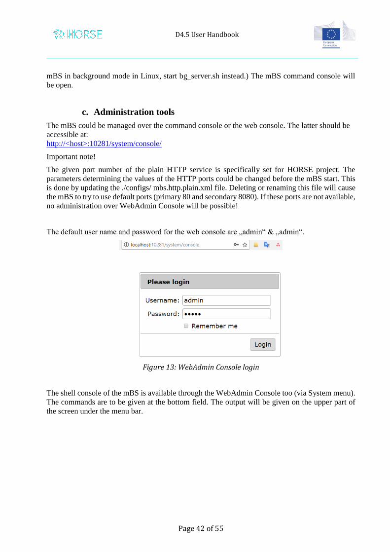
The default user name and password for the web console are „admin“ & „admin“.
Figure 13: WebAdmin Console login
The shell console of the mBS is available through the WebAdmin Console too (via System menu).
The commands are to be given at the bottom field. The output will be given on the upper part of
the screen under the menu bar.
D4.5 User Handbook
Page 43 of 55
Figure 14: Access to the shell console
When the mBS is started as a background process (Linux), there is no terminal console. In this case the command console is available only via the WebAdmin.
d. Configuration of the Websockets server
To set the correct port of the websockets server open the Configurations page from OSGi menu of
the WebAdmin console.
D4.5 User Handbook
Page 44 of 55
Figure 15: Configurations list
Navigate to „Prosyst Websockets Server :: Core“ and click to open the configuration.
D4.5 User Handbook
Page 45 of 55
Figure 16: Websockets server configuration
Provide the correct port (the agreed port for HORSE broker is 10282) and save the configuration.
e. Installation of the needed components
As mentioned above, the ZIP archive contains the components (OSGi bundles) for several HORSE
applications. The installation of the needed set of bundles is managed by script commands.
Execute the console command “kitman.ls” to get the list of available scripts.
Execute the console command “kitman.i “ plus the number of the script in order to install its
components.
D4.5 User Handbook
Page 46 of 55
Figure 17: Kitman scripts
The same commands can be executed via the WebAdmin console shell (Figure 14).
Once the HORSE Message Broker is installed, it could be accessed on the following URI:
ws:\\<host>:<port>,
where the “host” is the IP or name of the host machine and “port” is the selected websockets server
port (e.g. 10282).
f. Configuring the Broker
The proper operation of the Broker requires the correct configuration of the connection to the history database. The configuration panel is accessbilbe from the OSGi/Configuration submenu of the Web Admin Console (see Figure 15)
Upon starting the module, it creates (if not existing) the table “MESSAGE” for storing copies of all received messages.
D4.5 User Handbook
Page 47 of 55
Figure 18: HORSE Broker Configuration
g. Configuration of the Dispatcher
As the Dispatcher is mediating multiple Brokers, it should register itself to each of them as a messaging agent. The parameters of these registrations are provided as configurations as shown in Figure 19.
Figure 19: HORSE Dispatcher Configuration
D4.5 User Handbook
Page 48 of 55
h. Stop of the mBS
Recommended. Via console command (terminal or web console shell)
Execute “exit” to gracefully stop all running services and ultimately stop the Java process.
In case the graceful shutdown is not possible it is possible to kill the Java process. There is a risk
of losing data.
i. Restart the mBS
The standard way to restart the server is to perform a start after the graceful shutdown. The mBS
will reload all components and configurations from the previous session (the connections to the
websockets clients could be lost).
In case of problems by start or out of some other reasons It is possible to reset the mBS and perform
a “clean” start as follows:
- Delete the local storage (./bin/vms/jdk/storage folder). A backup is recommended.
- Also recommended is to back up the previous log files (./bin/vms/jdk/logs folder).
- Start and configure the mBS and its components.
j. Retrieving the log files
The mBS creates and maintains local log files. They are located in the ./bin/vms/jdk/logs folder. They could be retrieved from the file system (scp, ssh…) or via the WebAdmin console (OSGi -> Log files)
3. Working with the Broker
In order to be able to exchange messages between your agent and the Broker, the following steps
need to be executed:
Initiate a connection
Send a control message to register your agent
Start sending and receiving payload messages
a. Initiating a connection
You have to open a websocket connection from your websocket client to the websocket server
running on the Broker’s mBS
ws:\\<host>:<port>, as stated above
The alias for the connection is "/horse/message" (this can be changed and/or discussed)
The ZIP archive contains an image of a HORSE Message Agent. It could be installed using the
Kitman scripts on the same or remote host. We have provided a Jetty-based websocket client.
D4.5 User Handbook
Page 49 of 55
b. Registering the agent
The registration of an agent is done by sending a special type of message to the Broker, the Control
message. It is a Json message with the following format
• ___CONTROL___ It is obligatory that the message is prefixed by this special string!
• It is followed by a JSON Object with two mandatory fields:
"ID" bearing the unique name of the agent.
"Operation" with two possible values: "connect" and "disconnect" in order to add or remove
the agent from the Broker’s list of agents;
A number of other parameters could be provided, if needed.
Once the agent is registered by the Broker it can send and receive Json-based payload messages
with the following format:
• Topic (can be any String) - default value is empty string ("")
• Priority (from 1 - Lowest to 5 - Highest) - default value is 1 (Lowest)
• Receivers (a comma-separated list of IDs, if a star is included all receivers will get this
message) - default value is * (all recipients)
• Type (1 for Debug, 2 for Event, 3 for System, 4 for Custom) - default value is 4 (Custom)
• Timestamp - The timestamp of the initial sending of the message. Long data type;
automatically set by first broker the message passes through.
• Subtype (fully customizable, can be any string).
• SenderID - the ID of the sending client. Should be automatically set by all implementations
to the sending client.
• MessageID - a timestamp in milliseconds corresponding to a message which wants to be
answered back to. Default value is "" (empty string).
• ResponseMessageID - The timestamp of the message of the sender to which we are sending
a reply message. This is meant to say that the message we are sending is an answer to a previous
message with a specific senderID and messageID. Default value is "" (empty string).
• Internal – if set, this flag sends the message to the agents of the broker which is directly
connected (i.e. without connecting to the dispatcher) to the sending client
• ExternalBrokers – If a message is to be sent over the dispatcher, this shows which dispatcher
broker this should get sent to. This is a comma-separated list. It corresponds to the ID of the web
socket connection between the dispatcher and the corresponding message bus.An asterrisk ("*")
sends to all brokers.
D4.5 User Handbook
Page 50 of 55
• SenderBroker – If a message is to be relayed using the dispatcher, this field is normally set
by the dispatcher to note the sending message broker. It is also used to protect against looping of a
message between the broker and dispatcher.
• The body (payload) can be any JSON Object with proper syntax - default value is empty
JSON Object "{}.
Example:
{"Topic":"test_domain/topic/something",
"Priority":"1",
"ResponseMessageID":"1234567",
"Receivers":"Test_client_2,something,*",
"SenderID":"dummy_component",
"MessageID":"1484816109871",
"Type":"3",
"Timestamp":"123413412"
"Subtype":"GETAGENTLIST",
"Internal":"true",
"ExternalBrokers":"test_broker_2",
"SenderBroker":"test_broker_1",
"Body":{}}
4. Useful tools
We have provided several useful options to simulate and test the HORSE messaging, as well as
access the information of the Broker:
a. Web based interface
A test.html file is available at http://<host>:<port>/root/test.html, where the “host” is the host name
or ip of the machine running the HORSE messaging component (agent or broker) and “port” is the
port of the HTTP server on that machine (e.g. 10281). It has a hard-coded alias of "/horse/message"
which can be changed in the HTML file.
D4.5 User Handbook
Page 51 of 55
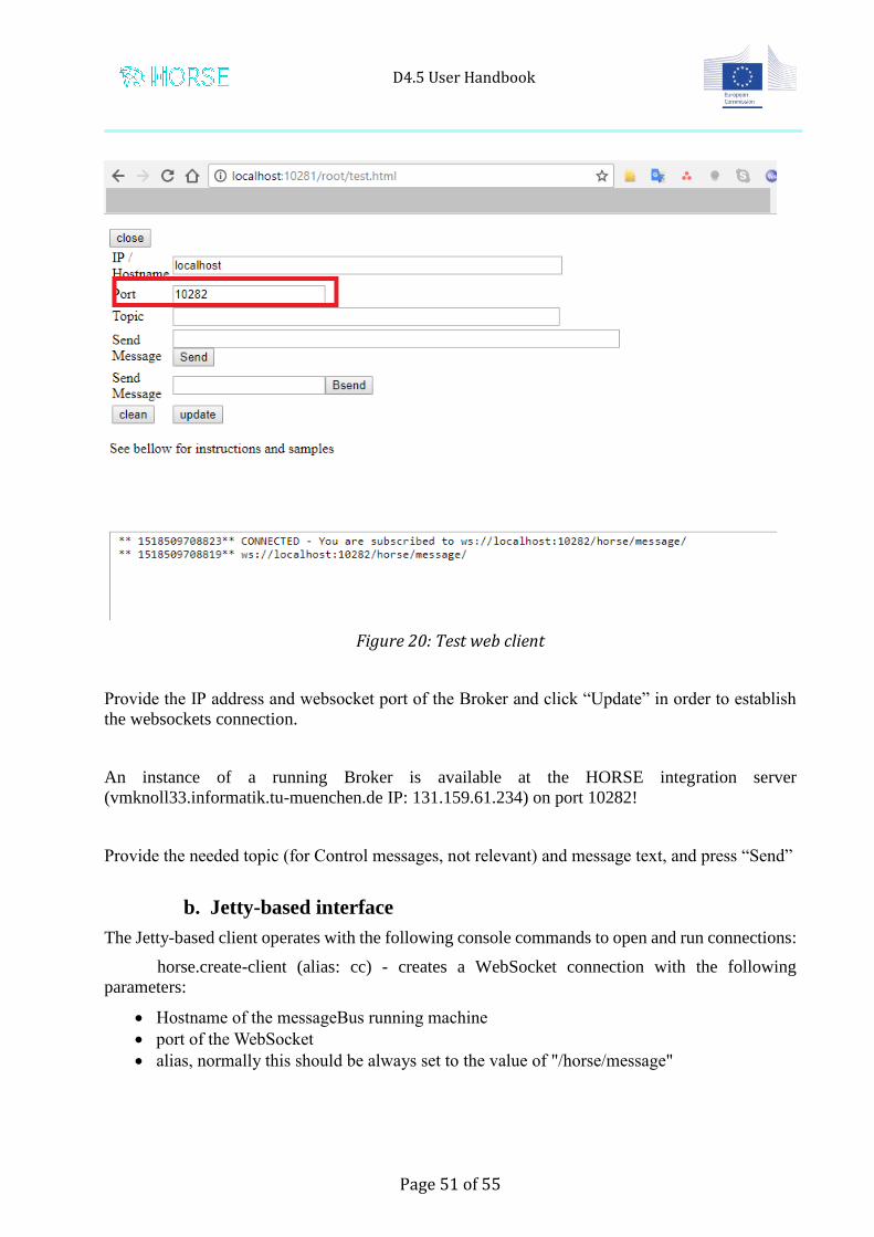
Figure 20: Test web client
Provide the IP address and websocket port of the Broker and click “Update” in order to establish
the websockets connection.
An instance of a running Broker is available at the HORSE integration server
(vmknoll33.informatik.tu-muenchen.de IP: 131.159.61.234) on port 10282!
Provide the needed topic (for Control messages, not relevant) and message text, and press “Send”
b. Jetty-based interface
The Jetty-based client operates with the following console commands to open and run connections:
horse.create-client (alias: cc) - creates a WebSocket connection with the following
parameters:
Hostname of the messageBus running machine
port of the WebSocket
alias, normally this should be always set to the value of "/horse/message"
D4.5 User Handbook
Page 52 of 55
newly requested ID (can be any string value)
a map with all the other parameters of the client, such as {param_1=value_1,
param_2=value_2, ….}
horse.list (alias: ls) - lists all active clients <on the side of the client mBS!>
horse.send-message (alias: sm) - sends a message ot the messageBus to
redistribute; note that the active client has to have sent a control message to register
(i.e. the create-client command has to have had been executed) before this operation
can be completed successfully; the parameters are as follows:
id of the active client to send with (seen with ls command)
topic of the message
priority of the message (1-5)
type of the message (1-4)
subtype of the message (any string)
internal flag - if set, sends the message to the internal message broker agents.
recipients (comma-separated string of values, * for all clients)
externalBrokers (comma-separated string of values, default value is empty
string)
return flag - if true, the message is sent with an additional JSON Field
(MessageID) to denote that it wants to be answered back to
response message ID of the message
body (valid JSONObject string)
horse.stop-client (alias : sc) - stops a web socket client with the given ID as
argument.
c. Monitoring the connection
There are two ways to monitor which clients have connected (and registered) to the
message bus:
via console commands
horseserver.ls will print information about all clients (server-side!)
horseserver.reset in case the thread to send messages stops working, normally
this isn't needed and is for debugging purposes only
horseserver.stop-client (alias : sc) - stops a web socket client with the given ID
as argument.
via REST at http://<host>:<port>/restdoc/swagger-ui/index.html
the /horse/ids method is a simple listing mechanism for the used registered IDs
of clients (server-side!)
The /horse/details/{id} method is meant to provide additional information for
a specific ID.
D4.5 User Handbook
Page 53 of 55
4 Appendix B
HORSE BOS Adapter Installation and Usage Guide
1. Introduction
Since similarly to the HORSE Messaging Middleware components, the BOS Adapter components are distributed as OSGi bundle and executed in the same environment (Bosch IoT Gateway Software, former mBS), this guide will cover only the specific operations.
2. Setup
The BOS Adapter binaries should be requested by Bosch Software Innovations (Venelin Arnaudov, [email protected]):
horse-bos-adapter_YYYYMMDD.zip - the binaries and scripts of the BOS Adapter modules.
Since the BOS Adapter components are executed in the mBS, the horse-mw-core package, providing the mBS is required.
The latest version of the BOS Adapter binaries can be requested by Bosch Software Innovations
The installation, configuration and start of the mBS is explained in Appendix A.
The installation of the BOS Adapter modules is done by executing kitman commands as shown Section 2.e Installation of the needed components of Appendix A (Figure 17).
Components 2, 3 and 4 provide interfaces to the industrial protocols PLC, EtherCAT and OPC-UA, while the coordinator (#5) is mediating between the protocol interfaces and the HORSE Messaging Middleware.
The next figures show the configuration forms for each components.