Page 1
© MARIO consortium Page 1 of 35
D6.5 Final Report on MARIO’s Control
Architecture_Final version
Project Acronym: MARIO
Project Title: Managing active and healthy ageing with use of caring service robots
Project Number: 643808
Call: H2020-PHC-2014-single-stage
Topic: PHC-19-2014
Type of Action: RIA
Page 2
643808
© MARIO consortium Page 2 of 35
D6.5
Work Package: WP6
Due Date: July 2017
Submission Date: 19/6/2018
Start Date of Project: February 2015 February 2015
Duration of Project: 36 Months
Organisation Responsible of Deliverable: CNR
Version: 4
Status: Final
Author name(s): Stefano Nolfi, Alessandra Vitanza, Filippo Cantucci, Alessandro Russo (CNR), Alex Gkiokas, Maria Ramos Montero (ORTELIO), Giuseppe Pappalardo (R2M), Valentina Presutti (CNR)
Institutions CNR, ORTELIO, R2M
Reviewer(s): Massimiliano Raciti (R2M),
Alex Gkiokas (ORTELIO)
Nature: R – Report P – Prototype
D – Demonstrator O - Other
Dissemination level: PU - Public CO - Confidential, only for members of the
consortium (including the Commission)
RE - Restricted to a group specified by the consortium (including the Commission Services)
Project co-funded by the European Commission within the Horizon 2020 Programme (2014-2020)
Page 3
643808
© MARIO consortium Page 3 of 35
Revision history Version Date Modified by Comments
1 15/7/2017 Stefano Nolfi Prepared a first version obtained by extending the preliminary version of the deliverable 6.4. In particular the description of the work carried by CNR has been updated
2 25/6/2017 Giuseppe Pappalardo (R2M)
Added the description of the work carried by R2M
3 26/6/2017 Maria Ramos Montero (ORTELIO)
Added the description of the work carried by ORTELIO
4 27/7/2017 Stefano Nolfi Revised the document on the basis of the feedback provided by the reviewers
5 31/7/2017 Stefano Nolfi Revised the document on the basis of the feedback provided by Dolan Aisling (GALWAY).
6 19/6/2018 Stefano Nolfi and Valentina Presutti (CNR)
Revised on the basis of the request included in the review report of the project. Added section 10.
Page 4
643808
© MARIO consortium Page 4 of 35
Copyright © 2015, MARIO Consortium
The MARIO Consortium (http://www.mario-project.eu/) grants third parties the right to use and distribute all or parts of this document, provided that the MARIO project and the document are properly referenced.
THIS DOCUMENT IS PROVIDED BY THE COPYRIGHT HOLDERS AND CONTRIBUTORS "AS IS" AND ANY EXPRESS OR IMPLIED WARRANTIES, INCLUDING, BUT NOT LIMITED TO, THE IMPLIED WARRANTIES OF MERCHANTABILITY AND FITNESS FOR A PARTICULAR PURPOSE ARE DISCLAIMED. IN NO EVENT SHALL THE COPYRIGHT OWNER OR CONTRIBUTORS BE LIABLE FOR ANY DIRECT, INDIRECT, INCIDENTAL, SPECIAL, EXEMPLARY, OR CONSEQUENTIAL DAMAGES (INCLUDING, BUT NOT LIMITED TO, PROCUREMENT OF SUBSTITUTE GOODS OR SERVICES; LOSS OF USE, DATA, OR PROFITS; OR BUSINESS INTERRUPTION) HOWEVER CAUSED AND ON ANY THEORY OF LIABILITY, WHETHER IN CONTRACT, STRICT LIABILITY, OR TORT (INCLUDING NEGLIGENCE OR OTHERWISE) ARISING IN ANY WAY OUT OF THE USE OF THIS DOCUMENT, EVEN IF ADVISED OF THE POSSIBILITY OF SUCH DAMAGE.
Page 5
643808
© MARIO consortium Page 5 of 35
Executive Summary
The utilisation of mobile robots for the realisation of robot companions that support and
monitor human users in their everyday activities present several potential advantages. It
enables to maximise the information that can be extracted from the human user without
restructuring the environment with embedded sensors and computing devices. Further, it
permits the realization of a natural and effective interaction with the user. It enhances the
usability of other interaction modalities (e.g. interactions mediated by a touch screen or
by natural language) by enabling the robot to reach an appropriate relative position with
respect to user.
The achievement of these objectives, however, requires the development of robots
possessing robust and effective perceptual and motor capabilities able to operate
autonomously for prolonged periods of time in dynamic environments.
In this document we briefly describe the perceptual and motor capabilities that we
developed to enable MARIO to display these functionalities. The rationale behind the way
in which these components have been developed is described in D6.4. Here we provide
a guide to technical users and developers on how to use the available motor and
perceptual capabilities and on how to incorporate them into applications. In this
document, we restrict to the analysis of the perceptual and motor components of the
robot. The overall software architecture of the robot and the software components that
are not directly related to motor behaviours are described elsewhere.
Page 6
643808
© MARIO consortium Page 6 of 35
Table of Contents
Executive Summary ........................................................................................................................ 5
1. Introduction ................................................................................................................................. 8
1.1. Work Package 6 Objectives ............................................................................................ 8
1.2. Purpose and Target Group of the Deliverable ................................................................. 8
1.3. Relations to other Activities in the Project ...................................................................... 8
1.4. Document Outline ........................................................................................................... 8
1.5. About MARIO ................................................................................................................. 9
2. Summary ................................................................................................................................... 10
3. Software Architecture ............................................................................................................... 11
4. Perceptual and Motor Components ........................................................................................... 13
5. The User Approaching and Following Motor Component ....................................................... 21
6. The Navigate and Guide-Me Motor Components ..................................................................... 23
7. The Recharging Behavioural Component ................................................................................. 24
8. The Task Manager ..................................................................................................................... 26
9. The Navigation Graphic Interface ............................................................................................. 29
10. Development effort required to bring the Mario system to market ......................................... 31
11. References ............................................................................................................................... 35
Page 7
643808
© MARIO consortium Page 7 of 35
Index of Figures
Figure 1. Behavioural architecture of MARIO............................................................................................. 12 Figure 2. The KOMCOM client/server communication system .................................................................. 13 Figure 3. Example of a planned path. The white, black, and grey pixels represent the information contained in the occupancy grid. The crosses represent the initial and the target points. The blue circles represent the planned path......................................................................................................................... 16 Figure 4. MARIO and the recharging station. ............................................................................................. 26 Figure 5. A snapshot of the Navigation Graphic Interface. ........................................................................ 31
Page 8
643808
© MARIO consortium Page 8 of 35
1. Introduction
The objective of this deliverable is to provide a guide to technical users and developers
on how to use the motor and perceptual capabilities of MARIO and how to incorporate
them into new applications. The description of the software architecture of the perceptual
and motor components of Mario is provided in deliverable D6.4.
1.1. Work Package 6 Objectives
WP6 is made up of three primary tasks: (1) Development of MARIO’s behavioural
capabilities that has the objective of providing the robot with the required motor
behavioural skills, (2) Development of MARIO’s social skills that aim at enabling the Mario
robot to establish a rich and effective interaction with the user, and (3) Development of
MARIO’s adaptive engine that has the objective of enabling MARIO to adapt its behaviour
to the characteristics and to the needs of a specific user.
1.2. Purpose and Target Group of the Deliverable
This document is targeted to support the technicians’ use of MARIO and to aid developers
aiming to extend Mario’s functionalities.
1.3. Relations to other Activities in the Project
The work described in this deliverable is based on the input provided by WP1 (Definition
of Mario’s Functionalities), WP3 (Requirements for addressing the mitigation of
loneliness), and WP4 (Requirements for addressing a comprehensive geriatric
assessment). The work is also strongly dependent on the characteristics of the Mario
robot defined in WP2.
The software components developed in WP6 and described in this deliverable are
integrated with the ontology of the robot and with the robot reading and listening
component developed in WP5.
The motor behavioural and behaviour arbitration capabilities developed within WP6
constitute a component of the software applications integrated in WP7.
1.4. Document Outline
The document describes the perceptual and motor software components, the way in
which they operate, the commands that can be used to call them, and the way in which
they can be configured.
Page 9
643808
© MARIO consortium Page 9 of 35
Section 10 includes the description of the development effort required to bring the Mario
system to market requested in the final review report
1.5. About MARIO
MARIO addresses the difficult challenges of loneliness, isolation, and dementia in older
persons through innovative and multi-faceted inventions delivered by service robots. The
effects of these conditions are severe and life-limiting. They burden individuals and
societal support systems. Human intervention is costly but the severity can be prevented
and/or mitigated by simple changes in self-perception and brain stimulation mediated by
robots.
From this unique combination, clear advances are made in the use of semantic data
analytics, personal interaction, and unique applications tailored to better connect older
persons to their care providers, community, own social circle and also to their personal
interests. Each objective is developed with a focus on loneliness, isolation and dementia.
The impact centres on deep progress toward EU scientific and market leadership in
service robots and a user driven solution for this major societal challenge. The competitive
advantage is the ability to treat tough challenges appropriately. In addition, a clear path
has been developed on how to bring MARIO solutions to the end users through market
deployment.
Page 10
643808
© MARIO consortium Page 10 of 35
2. Summary
This document provides a guide to technical users and developers that describe the
available perceptual and motor software components, the way in which they operate, the
commands that can be used to call them, and the way in which they can be configured.
The rational behind the design of the components and the relation with respect to the
state of the art is discussed in Deliverable D6.4.
Page 11
643808
© MARIO consortium Page 11 of 35
3. Software Architecture
The behavioural architecture of MARIO is constituted by the perceptual and motor
components described in the Figure 1. The perceptual components extract categorical
information from the environment through the robot’s sensor. The motor components
enable the robot to move so as to generate the required behaviours on the basis of the
information extracted from the perceptual components.
The perceptual components operate continuously so as to enable the robot to
continuously update its representation of the user and of the environment on the basis of
the information that can be extracted from the robot’s sensors. By contrast, the motor
components are mutually exclusive and are activated by the task manager (see Section
9). Importantly, by modifying the relative position of the robot in the environment, the
motor components also modify the information that is sensed and that is perceived by the
sensor components.
Figure 1. Behavioural architecture of MARIO.
Page 12
643808
© MARIO consortium Page 12 of 35
In Section 4 we describe the perceptual components and the way in which they can be
configured and used. The motor components are described in Sections 5-7. The task
manager is described in Section 8. Finally, in Section 9 we describe the graphic interface
that can be used to monitor and debug the activity of the perceptual and motor
components.
As illustrated in the Figure 2, the communication between the perceptual and motor
components and the others software components and the communication between the
software running on the Linux and Windows PCs is carried out through the Kompai
communication component (KOMCOM), a client/server system developed in accordance
with the Web Application Messaging Protocol (WAMP, see http://wamp.ws/). It is standard
WebSocket protocol that enables both one-to-one communications (through remote
procedure called RPC), and one-to-many communications (through publish and
subscribe procedure systems called PubSub).
Figure 2. The KOMCOM client/server communication system
Page 13
643808
© MARIO consortium Page 13 of 35
4. Perceptual and Motor Components
The perceptual and motor components are software modules that enable the robot to
extract categorical information from the user and from the environment through the robot’s
sensors and to control the robot’s actuators. Perceptual components are organised in a
hierarchical structure in which high-level components operate on the basis of lower-level
components (Figure 1).
The simultaneous localisation and mapping system (SLAM) component infers the
position of the robot on the basis of the values sensed by the frontal laser scanner, update
the map of the environment. It is based on ROS and MRPT (Mobile Robot Programming
Toolkit) library. The SLAM system is used to create a 2D Occupancy grid map of the
environment and do self-localization at all times. The robot needs to be manually driven
in the environment with a slow-medium speed, due to the fact that the robot can miss
measurements during the time it takes to process the previous ones and thus get lost.
The self-localization and mapping can be realized by using one of the following
algorithms:
• ICP (Iterative Closest Point) (Besl, McKay, 1992): This algorithm enables the robot
to fill a map and self-localise when the current portion of the perceived environment
is sufficiently similar to the environment perceived during the preliminary phase, in
which the map was extracted (i.e. when approximately 60% of the detected
distances match with respect to the expected distances. This is only a very rough
estimate, since whether the robot manages to self-localise or not also depends on
the nature of the detected differences). When the match is lower than 40%, MARIO
tends to lose its ability to self-localize. This algorithm has problems with featureless
hallways. The map and the position are updated all the time.
• RBPF (Rao-Blackwellized Particle Filters) (Doucet, De Freitas, Murphy, and
Russell, 2000): This algorithm uses ICP as a base, adding the odometry data from
the robot and using a particle filter to match the pose of the robot with both
components. This algorithm calculates a more robust pose of the robot than using
solely ICP, although the pose of the robot and the map are only updated every
certain distance or angle (which can be modified in the configuration file). In this
case the odometry of the robot is calculated manually, given the linear and angular
speed of the motors, due to not being possible to access directly the motors’ data.
Both algorithms have parameters that can be modified in their configuration files. In both
cases, where the robot starts the mario node, default pose will be (x = 0, y = 0, theta =
0). This pose should be in the docking station, failure to do so will result in unmerged
maps and the robot getting lost.
Page 14
643808
© MARIO consortium Page 14 of 35
The component can be executed by running the mario node. When the RBPF algorithm
is used, mario_motors node (see below) should by executed as well.
The map obtained will be saved in a PNG file when the node is terminated. In case there
is a need for a debug map while the node is running, the interval of time to save the map
in a different PNG file, can be set in the configuration file.
The associated path planning component uses the current map to calculate a path
between two points given, as you can see in Figure 3. The algorithm will return a vector
of points to arrive from the start point to the goal. If an empty path is returned it is because
no possible path was found (there is an obstacle that is not possible to avoid, one of the
points is in an unexplored area, etc.). The algorithm calculates the path using only the x
and y components, not the angle.
Page 15
643808
© MARIO consortium Page 15 of 35
Figure 3. Example of a planned path. The white, black, and grey pixels represent the information contained in the occupancy grid. The crosses represent the initial and the target points. The blue circles represent the planned path
An algorithm can be used to fuse two existing maps. During the execution of this process
the robot should not move to avoid that it fail to self-localize.
The data flow from mario node is the following:
• Topic /pose: publishes the position of the robot in a ros geometry_msgs/Pose2D
format
• Topic /path_input: receives a ros geometry_msgs/Pose2D with the start point and
another ros geometry_msgs/Pose2D with the goal point.
• Topic /path_output: publishes a boolean according to whether the path has been
found and ros geometry_msgs/PoseArray with all the intermediate positions
between the two points given in the /path_input topic. PoseArray contains a
quaternion for the orientation, but it is not calculated.
• Topic /load_merge_maps: receives a boolean to start the load and merge process.
• Topic /load_merge_maps_result: publishes a boolean with the result of the load
and merge process.
The mario_motors node is a component in charge of getting the information from the
motors and controlling them. The communication is done with HTTP protocol, although
the information is translates to/from a ROS message to facilitate its use. It is necessary
that the MAPPER API developed by Robosoft is running to allow the communication with
the motors.
The information flow from mario_motors node is the following:
• Topic /speed: publishes two float32 with the linear and angular speed of the robot
and a boolean to enable/disable the motors.
• Topic /control: receives two float32 with the linear and angular speed and a
boolean to enable/disable the motors. This information will be sent to the motors.
The orders sent by the manual controller have higher priority than this component.
Because of that, in an emergency case, the robot can be easily controlled.
The mario_default.launch will run lasers, mario_motors and mario nodes. Mario_full will
run the same as mario_default and additionally the Intel Realsense camera.
Page 16
643808
© MARIO consortium Page 16 of 35
The easier and more user friendly way to start and stop the Mario nodes, is through the
Web Interface implemented in the web_api directory of the project. It makes the above
choices (start default or full and stop the nodes) accessible through a web browser,
running in a device connected to the same wifi with the robot. However, due to security
reasons, in order for access to this interface to be obtained, one has to log in first, by
entering registered caregiver credentials.
The obstacle perceptual components, developed by CNR, extract information about
nearby obstacles that need to be avoided. This perceptual component operates on the
basis of the information extracted from the laser range sensors and from the depth
camera.
The data elaborated from the component can be accessed directly through the
“get_proximities (Array<ProximitiesData>)” method that returns a vector of proximity
distances distributed around the full 360o of the robot. ProximitiesData is a structure that
includes for each element the actual distance, the angle relative to the robot’s orientation,
and a type that indicates whether the detected obstacle corresponds to an object present
in the map or not. Moreover, the component provides the “get_peripersonal_proximities
(Array<ProximitiesData>)” method that returns the subset of proximity distances relative
the direction of motion of the robot. This information is used by the motion controller to
check whether the portion of space in which the robot is going to move is free from
obstacles or not.
The moving-object perceptual component, developed by CNR, operates on the basis of
the state sensed by the laser range finders. This software operates by processing how
the distance detected by the laser ranges vary over time during the last 5 seconds and
by clustering readings corresponding to adjacent portions of space. The software also
pre-process data so to filter out noisy readings and to filer out “shadows”, i.e. variations
caused by changes in perceptual occlusions rather than by movement of the detected
objects.
The data elaborated by this component can be accessed through the
“getDynamicObjects(Array<laserData>)”. Due to the poor resolution of the rear laser, the
accuracy of the data detected is greater for objects located in the frontal side of the robot
than for objects located in the rear side.
The leg-detection perceptual component, developed by CNR, operates on the basis of
the state sensed by the laser range finder and on the basis of the information contained
in the map of the environment. This software component operates by: (i) identifying the
readings of the laser range finder that do not match with the information stored in the
Page 17
643808
© MARIO consortium Page 17 of 35
map, (ii) clustering this information into a vector of inferred objects that were absent while
the map was created, (iii) filtering out the objects that are too big or too small to
correspond to people, and (iv) estimating the probability that each object corresponds to
a leg or to the legs of a person. This software library therefore receives as input the map
of the environment, the estimated position of the robot, and the current state of the laser
range finders and produces as output a vector of possible leg objects with associated
information (i.e. position, size, probability).
The data elaborated from the component can be accessed directly through the “get_legs
(Array<LegsData>)” method that returns the list of perceived objects. LegsData is a
structure that includes for each element the position of the centre of the detected leg, the
radius, and the probability that the object detected correspond to a human leg.
The Microsoft© Skeletal perception component operates on the basis of the Kinect depth
camera and enables to recognize human bodies. More specifically, it allows for the
recognition of the skeleton of a single or of multiple persons in the filed of view of the
camera (i.e. the major segments forming the skeleton and the position of the joints linking
the segments). The reliability of the library depends on the relative orientation of the
persons located in the field of view of the camera. More specifically the probability of
correctly recognising the individuals is maximised when they have a standing or sitting
posture and are located in front of the camera. The reliability deteriorates when the
individuals are standing sidewise, have a different posture, or are only partially located
within the field of view of the camera. The probability of correctly recognising users also
deteriorates when the robot moves as a consequence of the reduced stability of the
perceived image and of the intrinsic noise of the images. This library enables the
recognition of the individual’s skeleton located in the filed of view of the camera at a
distance between 1.2 and 3.5 m, approximately. We complemented the library with an
additional software component that estimates the probability that the skeleton
corresponds to the target user and that tries to infer the orientation of the skeleton on the
basis of the positions of the segments and of the joints. Overall this component produces
as output a vector of detected skeleton with associated position and orientation
information and probabilities.
The information generated by the component can be accessed by subscribing to the topic
with the “Komkinect.bodies” and by accessing the JSON structures that encode for each
detected skeleton the following information {FrameEdges ClippedEdges;
TrackingConfidence HandLeftConfidence; HandState HandLeftState;
TrackingConfidence HandRightConfidence; HandState HandRightState;
bool IsRestricted; bool IsTracked; IDictionary<JointType, JointOrientation>
JointOrientations; IDictionary<JointType, Joint> Joints; PointF Lean; TrackingState
Page 18
643808
© MARIO consortium Page 18 of 35
LeanTrackingState; ulong TrackingId} and {int isSkel; point skelPosition; double
SkelOrientation; double SkelReliability}. These structures include information about the
positions and orientations of each detected skeleton as well as information about the
position of all detected skeleton parts, information about the angle of the joints, and
confidence information concerning the probability that the structure detected corresponds
to a human skeleton.
The tag detection perceptual system is a software component, developed by CNR, which
operates on the basis of the RFID receiver. It returns the list of tags detected. When
present, the tags uniquely identify the user identity or the identity of tagged objects (e.g.
the user’s wallet or keys).
The library provide the following methods: (1) “RFIDStart()” that sets the receiver in the
operation mode, (2) “RFIDStop()” that sets the receiver in a stand-by mode and that can
be used to save power, (3) “RFIDGetList(Vector RFIDtags)” where RFIDTAGS is a
structure that contains for each element the ID of the detected TAG.
The library runs on the Windows computer and can be accessed through the KomCom
API developed by R2M. More specifically, it can be accessed by subscribing to the topic
with the “kompai.rfid.data” realm and by accessing the JSON structures that encode the
UID of each detected tag.
The face detection component detects human faces. We developed in parallel two
version of this component that operates on the basis of the Kinect and on the basis of the
Intel Realsese ZR300 camera, respectively. The first version has been developed by R2M
and the second version by ORTELIO.
The version that operates on the basis of the Kinect can be accessed by subscribing to
the topic with the “kompai.kinect.face_location” realm and by accessing the JSON
structures that return a map with the following information {bool "isTracking", int x, int y,
int width, int height}. The map includes information about tracking success, the location
of the face detected on the x and y-axis (top/left point), the width and the height of the
portion of the image that includes the detected face.
The version that operates on the basis of the Intel Realsense ZR300 camera can be
accessed by using the topic described in the following paragraph.
The face recognition component, developed by ORTELIO, recognizes human faces. It
operates on the basis of the Intel Realsese ZR300 camera and on the basis of a database
of face images. The component can only recognize people that are included in the
database (faces corresponding to different people are recognized as the most similar face
included in the database).
Page 19
643808
© MARIO consortium Page 19 of 35
The database is generated from video files to allow the process to take place faster than
taking photos of the subjects and two scripts have been developed to help to create the
database. The database must to be in conf/face_db folder.
The information shared from mario_motors node is the following:
Topic /faces: publish a vector of the faces detected. Every face has width, heigh
and the x and y coordinates for the top left corner of the rectangle that contains
the face. All of these variables are int32 format.
Topic /humans: publish a vector of the humas detected. Every face has width,
heigh and the x and y coordinates for the top left corner of the rectangle that
contains the human. All of these variables are int32 format.
Topic /person_vector: publish a vector of the faces recognised. Every face
recognised has a float32 distance(the probability of the result given is correct), a
face(width, height, x and y of top left corner), an int32 label for that person and a
string with the name of that person.
The user-monitoring component, developed by CNR, is a high level perceptual
component that recognizes the presence and the relative position of the user by fusing
and integrating the information extracted from the lower-level perceptual components
described above. More specifically, this component operates on the basis of the output
produced by the moving-object, leg detection, skeletal tracking, face detection, face
recognition, and the tag recognition system. This information is used to generate a vector
of perceptual clusters that corresponds to potential target persons. Each cluster includes
one or more perceived person’s parts, e.g. legs, skeleton, face, tag, as well as information
encoding the position and the orientation of the cluster and the likelihood that the cluster
corresponds to the target user. Importantly, the vector of clusters and the associated
information are updated not only on the basis of the current perceived information but
also on the basis of the previous clusters (i.e. on the basis of the clusters calculated on
the basis of the combination of the previous sensed information and on the basis of dead-
reckoning information). This enables the robot to operate on the basis of the object
permanence principle, i.e. to understand that objects continue to exist even when they
become temporarily not observable. As described below, the output of the user detection
component is used by the robot to approach and/or follow the user. In addition to that, it
is used to update the robot’s knowledge base. In particular, this component is used to
update the robot’s knowledge concerning: the current position and orientation of the user,
the posture of the user, the movement that the user is performing, the relative distance
and angular offset between the robot and the user, the position of perceived tagged object
etc.
Page 20
643808
© MARIO consortium Page 20 of 35
The data elaborated from the component can be accessed directly through the “get_users
(Array<UsersData>)” method that returns a vector of clusters, i.e. a vector of perceived
human persons. UsersData is a structure that includes for each element the estimated
centre of the position of the person over the plane, the estimated orientation of the person,
the leg objects detected (if any) associated to the person, the skeleton object detected (if
any) associated to the person, the tag object detected (if any) associated to the person,
and the probability that the detected person corresponds to the identity specified.
Finally, the environmental-monitoring component, developed by CNR, is a high level
perceptual component that recognizes of the presence of relevant objects located in the
space surrounding the robot. The component operates on the basis of the output
produced by the mapping, self-localization, obstacle detection, and tag recognition
perceptual components.
The data elaborated from the component can be accessed directly through the
“get_objects (Array<ObjectsData>)” method that returns a vector of objects. ObjectData
is a structure that includes for each element the estimated barycentre of the object over
the plane, the estimated orientation of the object, the ID of the object type, and the
probability that the object corresponds to the object type.
Page 21
643808
© MARIO consortium Page 21 of 35
5. The User Approaching and Following Motor Component
The approaching and following behavioural component enables MARIO to detect a
person, approach and then remain near her/him once the person has been reached.
The behavioural component assumes that the robot already has a map of its environment.
It can operate effectively even when the robot is unable to self-localise but operates more
robustly in normal conditions in which the self-localisation modules permit to the robot to
establish its own location in the map.
In the default mode, the behaviour is realised in three continuous phases. First the robot
orients toward the person, then it navigates toward the person by avoiding obstacles, and
finally it stops at a desired distance from the target user (the desired distance is a
parameter that can be varied depending on the circumstances). If the person moves,
MARIO will move as well by trying to stay at the desired distance from the person.
The behavioural module continually updates the relative position of the person with
respect to the robot during all phases (i.e. both when the robot move to approach the
person and when the robot stay still) by publishing the information extracted by the user-
detection component.
The behavioural component can be executed in three modes. In the “approach” mode it
produces the behaviour described above. In the “orient” mode it orients toward the user
but it does not approach the user. In the “monitor mode” it simply monitors for the user
presence without moving. In all cases, the controller publishes the information concerning
the relative position of the person located nearby the robot, if present. In particular, it
publishes the probability that the detected object is a person, the distance of the person,
and the relative angle of the person with respect to the robot.
This motor component can be executed via the task manager (see Section 9) through the
following command:
http://{hostname}:{port}/marvin/eventbus/topics/ApproachFollow
The component can be configured by editing the AppConfig.ini configuration file that
includes the parameters described and explained below:
[TASK MANAGER]
enable = true
Page 22
643808
© MARIO consortium Page 22 of 35
→ Enable/Disable the Client’s ability to interact with Task Manager (T.M.)
uri = "http://xxxx.it"
address = "X.X.X.X"
→mutually exclusive parameters for the connection with the T.M.
port = 80
→T.M. port
subscribername = "BehaviourModule"
→ Motion Behaviour Module name into the T.M. subscribers list.
path="/marvin/eventbus/topics/"
→subscribtion path
GET_topic="test"
→ the name of the topic used for GET messages.
POST_topic="abilitystate"
→ the name of the topic used for POST messages.
publisher_topic="userInfo"
→ the name of the topic used for publishing data.
[PROTOCOL]
protocol="WAMP"
→ Communication Protocol supported: "WAMP"
[MODE]
mode="NO_GUI" (default operative mode)
→ "NO_GUI" || "VIS" || "SIMULATED"
behaviour = "monitoring"
→ Supported behaviours:
1. "monitoring": the robot monitors the presence of a possible user in
its field of view, using laser and Kinect sensor.
2. "orientation": the robot turns towards the identified user.
3. "approach": the robot moves in order to approach the identified
user, detecting obstacles.
running = false
→ just for developmental purposes. The default value can be false.
[ROBOT]
host_ip="X.X.X.X"
→ the robot IP
host_port=3000
→ the robot port
map_name="kkk0"
→ name of map file without ".png" extension.
map_path="C:\\Maps\\"
→ the path where the map files is located
TimeInterval=100
→ just for developmental purposes. The default value can be 100 ms.
Page 23
643808
© MARIO consortium Page 23 of 35
6. The Navigate and Guide-Me Motor Components
These motor components, developed by CNR, enable the robot to reach a given
destination. They operate on the basis of the navigation planning, the obstacle detection
components, and the leg detection component (in the case of the guide-me motor
component).
The guide-me component is an extended version of the navigation component that
checks the presence of the user and proceeds toward the destination only when the user
follows the robot.
This motor component can be executed via the task manager (see Section 9) through the
following commands:
http://{hostname}:{port}/marvin/eventbus/topics/Navigate {running:true, destination:{X,Y,Z}}
http://{hostname}:{port}/marvin/eventbus/topics/GuideMe {running:true, destination:{X,Y,Z}}
The component can be configured by editing the AppConfig.ini configuration file that
includes the following parameters:
[NAVIGATE MODE]
NavigateBehaviour = "Navigate"
→ Supported behaviours:
1. "Navigate": the robot navigates, using path planning, to reach
a destination point.
2. "Guide_me": the robot navigates to a destination area
checking the presence of the user.
running = false
→ just for developmental purposes. The default value can be false.
mode="NO_GUI" (default operative mode)
→ "NO_GUI" || "VIS"
[NAVIGATE]
timeout = 15 s
[GUIDE-ME]
maxuserdistance = 1.5 m
timeout = 15 s
Page 24
643808
© MARIO consortium Page 24 of 35
7. The Recharging Behavioural Component
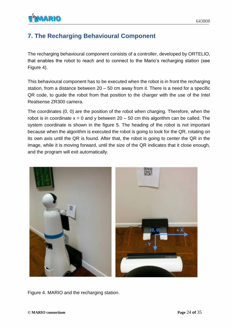
The recharging behavioural component consists of a controller, developed by ORTELIO,
that enables the robot to reach and to connect to the Mario’s recharging station (see
Figure 4).
This behavioural component has to be executed when the robot is in front the recharging
station, from a distance between 20 – 50 cm away from it. There is a need for a specific
QR code, to guide the robot from that position to the charger with the use of the Intel
Realsense ZR300 camera.
The coordinates (0, 0) are the position of the robot when charging. Therefore, when the
robot is in coordinate x = 0 and y between 20 – 50 cm this algorithm can be called. The
system coordinate is shown in the figure 5. The heading of the robot is not important
because when the algorithm is executed the robot is going to look for the QR, rotating on
its own axis until the QR is found. After that, the robot is going to center the QR in the
image, while it is moving forward, until the size of the QR indicates that it close enough,
and the program will exit automatically.
Figure 4. MARIO and the recharging station.
Page 25
643808
© MARIO consortium Page 25 of 35
This system should be calibrated in the position (0, 0) before the robot leaves the
recharging station. If the recharging station is fixed to a surface (completely steady in
regards to the qr) only one calibration is enough. However, if this is not the case, the
calibration should be done every time the robot finishes the charging of the battery.
The calibration part must be executed manually, it will create automatically a file with the
data of the QR, which will be read when the normal algorithm is running, and it will be
closed automatically.
Page 26
643808
© MARIO consortium Page 26 of 35
8. The Task Manager
The task manager is the software component that is responsible for initiating the activities
carried out by the robot on the basis of the current context and that arbitrate between
possible alternative activities that cannot be carried out in parallel. It is implemented in
Java as a software project named Marvin. It includes a publish/subscribe REST-based
communication protocol (Event Bus) that allows the external applications to be integrated
regardless of the programming language they are based on.
The task manager operates on the basis of: long term knowledge stored in the robots’
ontology, short term knowledge recently extracted from the environment through the
perceptual components, and affordances, i.e. opportunities for action. Affordances are
represented by triplets that encode the likeness that a certain knowledge state elicits or
inhibits a corresponding action.
The affordance network has been integrated into MARIO’s ontology through the
implementation of the Description and Situation Ontology Design Pattern combined with
a frame-based representation scheme (http://ontologydesignpatterns.org/
wiki/Submissions:DescriptionAndSituation). More specifically affordances
are represented as individuals of the class Affordance, which is modelled as a n-ary
relation connecting: (i) a class of situations that represents states of the world, (ii) the
afforded action or activity, which is any individual of the class action:Behavior, and (iii) a
quantity that indicate the likeness that the activity is triggered or inhibited and that is
represented by the property affordanceStrenght. The activity level of the premotor
states that determine whether a specific activity is triggered or terminated are
continuously updated on the basis of the state of the affording items and on the basis of
the affording strength.
As the Task Manager performs Abilities management and coordination, acting as a high-
level controller and supervisor, it is mainly responsible for activating, suspending,
resuming and terminating abilities. This mechanism is possible through a message-based
interaction approach, where the Task Manager communicate with the different abilities
by producing and consuming specific messages. The Event Bus acts as a message-
oriented middleware that allows architectural components to produce and consume
messages/events according to a topic-based publish-subscribe paradigm.
To manage the overall activities, the Task Manager sends control commands through
dedicated topics defined according to a JSON Schema, as following:
{
Page 27
643808
© MARIO consortium Page 27 of 35
" title": "Ability control command ",
" type " : " object " ,
" properties " : {
" command " : {
" description " : " The command ",
" type " : " string ",
" enum " : [" start " , " stop " , " suspend "]
}
},
" required " : [" command "]
}
The Abilities act as publishers for this topic and send messages carrying state change
events, while the Task Manager subscribes to the topic to receive state change
notifications produced by the Abilities. Typical notifications by the Ability to notify its
state change are defined according to the following JSON Schema:
{
" title " : " Ability state change event " ,
" type " : " object " ,
" properties " : {
" abilityName " : {
" description " : " The name of the ability whose state has changed " ,
" type " : " string "
},
" state " : {
" description " : " The state of the ability " ,
" type " : " string " ,
" enum " : [" ready " , " running " , " suspended "]
}
},
" required " : [" abilityName " , " state "]
}
A start command produces a state change event in the ability (e.g. Motor Behavioural
Component), transitioning to the running state is thus represented by the following JSON
object:
{
" abilityName ": " MotorBehaviour ",
Page 28
643808
© MARIO consortium Page 28 of 35
" state ": " running "
}
In line with the Event Bus API, the ability notifies its state change by sending a state
change event as a string in the body of a message published to the abilitystate topic
through a POST request:
POST .../ eventbus / topics / abilitystate
...
Accept : application / json
Content - Type : application / json
...
{
" correlationId " : " motorBehaviour-123" ,
" body " : "{\" abilityName \":\" motorBehaviour \" ,\" state \":\" running \"}"
}
Additional notification messages are provided since in MARIO the knowledge base is
organised as a networked ontologies. In order to update this knowledge base, for
example, the Behavioural Component can update the current position and orientation of
the user, the posture of the user, the movement that the user is performing, the relative
distance and angular offset between the robot and the user, the position of perceived
tagged object etc., according to the following JASON message:
{
abilityName: BehaviourModule,
state: "approach" || "monitoring" || "orientation",
userInfo: {
DistanceToUser: double, Reliability: double, } }
Page 29
643808
© MARIO consortium Page 29 of 35
9. The Navigation Graphic Interface
The navigation and graphic interface is a developmental tool that can be extremely useful
to debug problems affecting the robot’s sensors, motors, and the robot’s perceptual and
motor components. It is normally set off and can be turned on by editing the “running”
parameter in the NavigationInterface.ini configuration file.
Figure 5 shows an example of the information that can be visualized with the interface.
Figure 5. A snapshot of the Navigation Graphic Interface.
The upper part shows the objects detected by the robot in its surrounding area. The back
circles represent the robot. The black dots represent detected obstacles/surfaces. The
pink and green circles represent the location in which the robot detected a moving object
Page 30
643808
© MARIO consortium Page 30 of 35
and/or a human skeleton. More precisely, the green dashed circle indicates the perceived
user (target), obtained by the fusion of laser range finder information (colored pixels) and
human skeletons (bordeaux square) detected by the skeleton perceptual component. The
lower part displays laser reading that varied significantly during the last 5 seconds and
that consequently indicate the presence of moving objects. The vertical axis represents
time (within an interval of 5 seconds). The horizontal axis represents laser readings (from
frontal left side to the frontal right size and then from the rear right side to the read left
side). The data of the fontal and rear sides are divided by a line. The fact that the frontal
side is larger is due to the fact that the resolution of the frontal laser is higher than the
resolution of the rear laser.
The state of the graphic interface is updated continuously while the robot is moving and
consequently provides useful information that can help to understand the eventual
problems that cause inappropriate behaviours and/or the occurrence of malfunctioning in
the robot’s sensors and/or motors.
Page 31
643808
© MARIO consortium Page 31 of 35
10. Development effort required to bring the Mario system to market
In this section we describe the developmental effort required to improve the functionalities
developed in WP5 and WP6 so to reach a TRL9 maturity level (E.U., Work Program
2018-2020) which corresponds to a fully mature successful technology.
In the context of WP5, two research prototypes have been developed, i.e. sentiment
analysis and machine reading. In addition to these prototypes, the work in WP5 produced
an open large scale dataset (Framester) and an ontology network (Mario Ontology
Network) associated with a set of Java libraries, which have been integrated in MARIO
apps, used during the project experimental trials.
The machine reading tool named FRED (Gangemi et al., 2017) implements a method for
transforming natural language text to RDF knowledge graphs that include links to existing
LOD datasets e.g. DBpedia, WordNet, and alignments towards existing ontologies e.g.
Dolce Ultra Lite, Schema.org. The transformation process also includes tasks such as
frame detection, co-reference resolution, adjective semantics interpretation, modality and
negation detection, which are then formalised in the resulting graph. FRED is available
as both RESTful service and a python library. It is currently used in many research
applications, which provide a reasonable test-bed to make it evolve in terms of bug fixing
and accuracy improvement.
However, as a research prototype it has been developed without following an industrial-
oriented engineering methodology. For this reason, FRED would need additional effort to
be classified as a TRL9 maturity level technology. In particular, FRED would require the
development of an extended test suite of unit tests to ensure a more rigorous assessment
of its robustness, according to the needs of the possible client. In addition, depending on
the requirements of the intended client application, a number of integration and interface
tests would be needed. In order to engineer and perform such testing resources, a
minimum of six person/months and a maximum of twelve person/months would be
required, depending on the level of familiarity of the developer with the system. Another
aspect that may be considered in certain applications is the need of revise FRED’s code
in order to make it a native parallel computing software. In this case, the effort required
would be from eight person/months (minimum) to a maximum of twelve person/months,
depending on the level of familiarity of the developer with the system.
Page 32
643808
© MARIO consortium Page 32 of 35
The sentiment analysis component developed in the context of MARIO reuses existing
affective-based linguistic resources, such as SentiWordNet, for computing a sentiment
score for a given text. The implemented prototype is released as a RESTful service and
has also been integrated in some of the MARIO apps. In order to reach a TRL9 maturity
level, this service would need the development of testing resources and the performance
of additional testing: unit tests and integration tests. The effort required is estimated in
minimum three person/months to a maximum of six person/months, depending on the
level of familiarity of the developer with the system.
Framester is an open large-scale linked data knowledge graph, covering and interlinking
both linguistic, ontological and factual knowledge. In principle Framester can be used as
it is by any client application, as background knowledge. However, depending on the
client application at hand, it may require additional effort to perform data cleaning,
developing ad-hoc querying interfaces, or additional linking to domain-specific datasets.
Hence, to bring it to a TRL9 maturity level, we estimate that an effort of eight to twelve
person/months is required, assuming that an expert is involved in the development
process.
Mario Ontology Network (MON) is a network of ontologies that model a number of
relevant domains to assistive robotics applications. MON is associated with Lizard, a
Java-based software library that allows developers to reuse MON (querying, storing, etc.)
without forcing them to directly deal with RDF, OWL and SPARQL, which they may not
be familiar with. Lizard is a powerful and very useful tool in industrial context as many
developers prefer to use software libraries instead of dealing with knowledge
representation languages. It has been tested within the MARIO project as a tool for
building MARIO apps as natively integrated with MON. However, the number of apps
developed in the context of the project are not enough to classify Lizard as a TRL9
maturity level technology. In order to make it reach TRL9, an effort of minimum nine
person/months to a maximum of fifteen person/months must be spent in testing activities:
building resources for, and performing unit tests, interface tests, and integration tests.
For what concern the functionalities developed in WP6 a developmental effort is required
to: (i) improve the robustness of Mario’s autonomous recharging capability, (ii) improve
the robot SLAM and navigation system, (iii) extend the user’s detection range and the
efficacy of the follow software component, (iv) extend the perceptual libraries so to enable
the robot to reliably detect and discriminate the user from other persons, (v) improve the
integration between the perceptual and motor software, the dialog systems and the APPs.
The achievement of a robust autonomous recharging capability requires a partial re-
design of the recharging station to make it more compliant and the refinement of the
Page 33
643808
© MARIO consortium Page 33 of 35
software module responsible for the docking behavior. Overall this task might require an
effort of 10 man-months, approximately.
A second development effort is required to improve the robustness of the new open-
source SLAM system. This will require to develop a low-level software routine for
interfacing the software with the rear laser, to carry on extensive tests in varying
environmental conditions, and to tune the setting of software parameters. The capability
of the robot to move in densely occluded environmental area should also be improved by
using the navigation system to identify viable paths in a more robust way. Overall this
task might require an effort of approximately 12 man-months.
The software components that enable the robot to detect and approach the user can be
considered already mature for an in-house application scenario in which the robot needs
to interact with the user only. Indeed, the large majority of failures are temporal and do
not prevent the robot for achieving its goal. Moreover, users involved in test studies
reported to be satisfied by the current quality level of the system. An improvement in
reliability can be obtained by implementing the actuated degree of freedom on the
camera, that was planned in the original design of the robot, and the associated control
routines that also need to be integrated with the current perceptual software components.
This will enable to expand the view range of user’s detection. Moreover, the software
module responsible for the following capability should be improved to enable the robot to
deal effectively with a wider range of users’ movements and in particular to enable to the
robot to move faster when required. Overall this task will require a developmental effort
of approximately 8 months.
Extending the approaching and following behavior to enable the robot to interact reliably
with the user in the presence of other individuals requires additional developmental efforts
for improving the integration of the RFID tags detection component with the other
perceptual libraries, to test high quality RFID tags that can reduce the probabilities of false
negatives, to better fuse the information extracted through the face detection and
recognition components with the other perceptual information. Overall this task will
require a developmental effort of approximately 15 months.
Finally, the quality of the interaction between the user and Mario should be improved by
improving and extending the integration between the perceptual and motor software, the
dialog systems and the application. This includes limiting the usage of Mario speech to
the cases in which the user is located in a suitable relative position with respect to the
robot, allowing Mario to comprehend sentences such as “Mario come closer” by
regulating the distance at which the robot remain near to the user or “Mario please leave
me alone” by moving to the recharging station and by remaining there until the user does
Page 34
643808
© MARIO consortium Page 34 of 35
not call the robot again. Overall this task will require a developmental effort of
approximately 12 months.
Page 35
643808
© MARIO consortium Page 35 of 35
11. References
P.J. Besl, H.D. McKay, “A method for registration of 3-D shapes”, IEEE Transactions on Pattern Analysis and Machine Intelligence, 1992 A. Doucet, N. De Freitas, K. Murphy, and S.Russell (2000), “Rao-Blackwellised particle
filtering for dynamic Bayesian networks”, Proceedings of the Sixteenth conference on
Uncertainty in artificial intelligence. (pp.176–183)
Gangemi A., Presutti V., Reforgiato Recupero D., Nuzzolese A.G., Draicchio F., Mongiovì
M. (2017). Semantic web machine reading with FRED. Semantic Web 8(6): 873-893.