33
PRG, DACs, Slide 1 Monolithic D/A Converters •Basic DAC Specs •Basic MOS DAC Implementations •Performance Limits in DACs •Improved DAC Implementations
| Date post: | 03-Jan-2016 |
| Category: |
Documents |
| Upload: | guitarfrido |
| View: | 27 times |
| Download: | 0 times |

PRG, DACs, Slide 1
Monolithic D/A Converters
• Basic DAC Specs• Basic MOS DAC Implementations• Performance Limits in DACs• Improved DAC Implementations

PRG, DACs slide2
PRG, DACs, Slide 3
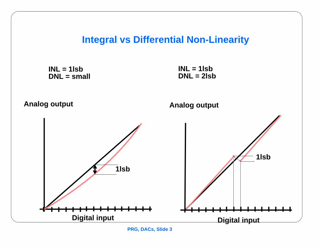
Integral vs Differential Non-Linearity
. .
Analog output Analog output
Digital input Digital input
1lsb
1lsb
INL = 1lsbDNL = small
INL = 1lsbDNL = 2lsb
PRG, DACs, Slide 4
High Speed ADC/DAC Techniques
Traditional Approach• Bipolar Technology
• Current-switched DAC
• LWT Thin-film resistors for >10 bits
Problems:• Not LSI Compatible
• No self-cal capability
Key Issues for CMOS LSI High-Integration ICs:• How do we integrate high-resolution DACs in CMOS?
• How do we calibrate or trim linearity for >10 bits?
Approaches:• Current-Switched DACs
• Resistor-String DACS
• Charge-Redistribution DACs
• Algorithmic DACs
PRG, DACs, Slide 5
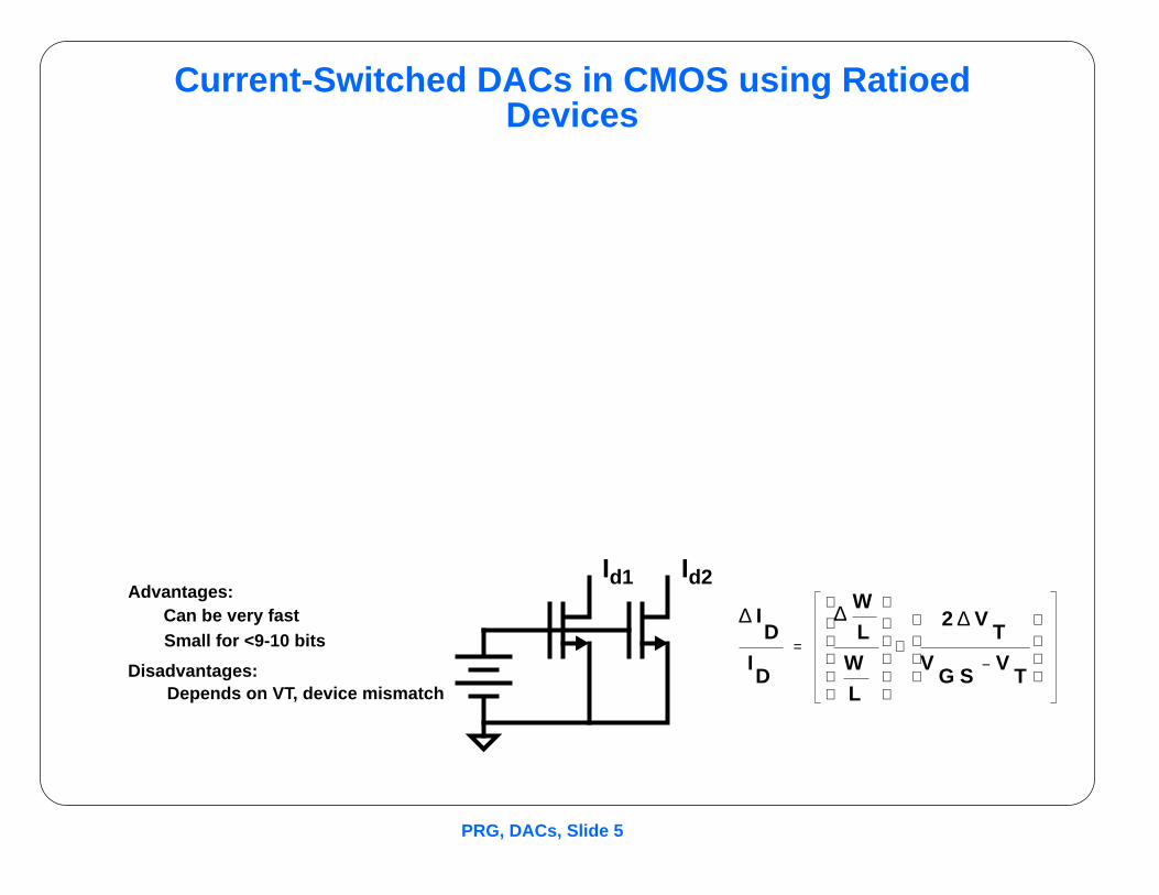
Current-Switched DACs in CMOS using RatioedDevices
Advantages:Can be very fastSmall for <9-10 bits
Disadvantages:Depends on VT, device mismatch
Id1 Id2
∆ ID
ID
∆ W
L
W
L
2 ∆ VT
VG S
VT
−
+=

PRG, DACs, Slide 6
Current-Switched DACs
Advantages• Inherent High Speed
• Easy to Generate Nonlinear Xfer
• Easy to Segment
• Amenable to Self-Cal
Disadvantages
• INL Depends on Transistor Matching
• Critically dependent on Rout of device

PRG, DACs, Slide 7
Resistor-String DACs

PRG, DACs, Slide 8
X-Y Decoding in R-String DACs
DiffusedResistors
Poly lines Metal pickup lines
Switch tree Analog Vout
Vref
Problems:Turning cornersProcess gradients
Ref: Hoff, Huggins et al, JSC Feb 79, Pellgrom, ISSCC90

PRG, DACs, Slide 9
Resistor-string DACs
Advantages• Inherently Monotonic
• Small area for <8 bits
Disadvantages• Large area for >8bits
• Susceptible to Process Gradients
• Susceptible to Contact Resistance
• Susceptible to Voltage Coefficient
Examples• Intel 8021, 80960

PRG, DACs, Slide 10
Resistors vs. Capacitors for Precision DACs
Representative Component Nonidealities, Typical Technologies
Componenttype
Matchingrange, 1sigma
TC, typical VC, typical
N+Poly-N+Poly cap,20u
0.1%-0.3% 40ppm/deg C 50ppm/V
P-Diffused R,3uX50u
0.2%-0.5% 1500ppm/ C 100ppm/V
N+Poly Resis-tor, 3x50u
0.2-0.5% 300ppm/ C <50ppm/V
Thin filmresistor, 3X50
0.1-0.3% 100ppm/ C 0
PRG, DACs, Slide 10.1
Polysilicon Capacitor and SwitchStructure

PRG, DACs, Slide 11
Charge-redistribution ADC
1. Sampling Mode

PRG, DACs, Slide 12
Charge-Redistribution ADC
2. Hold Mode

PRG, DACs, Slide 13
Charge-Redistribution ADC
3. Bit trials
PRG, DACs, Slide 14
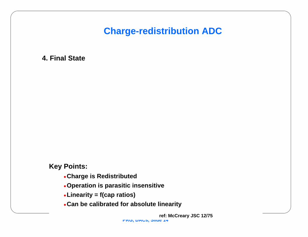
Charge-redistribution ADC
4. Final State
Key Points:• Charge is Redistributed
• Operation is parasitic insensitive
• Linearity = f(cap ratios)
• Can be calibrated for absolute linearity
ref: McCreary JSC 12/75

PRG, DACs, Slide 15
Conventional Charge-Redistribution DACs
Advantages:• Inherent Sample/Hold
• MOS Compatible
• Can be made inherently monotonic
• Potential for very low power
Disadvantages• Trim or self-cal required for >10bit linearity
• Requires cap in process
DAC Summary
• Current-switched widely used for high-speed video, low-res
• Cap arrays often used in precision data acquisition or telecom apps
• R-string used mostly in capacitorless technologies
PRG, DACs, Slide 16
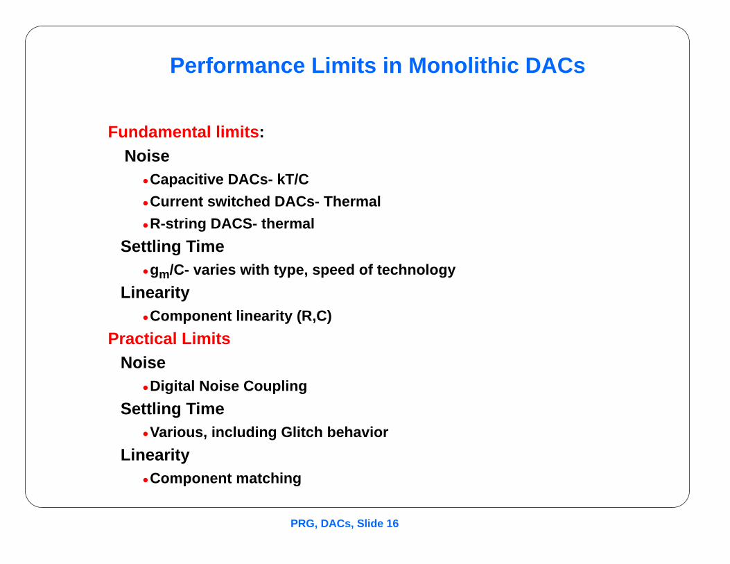
Performance Limits in Monolithic DACs
Fundamental limits :Noise
• Capacitive DACs- kT/C
• Current switched DACs- Thermal
• R-string DACS- thermal
Settling Time• gm/C- varies with type, speed of technology
Linearity• Component linearity (R,C)
Practical LimitsNoise
• Digital Noise Coupling
Settling Time• Various, including Glitch behavior
Linearity• Component matching

PRG, DACs, Slide 17
Performance Limits in Monolithic DACs
• Linearity
• Settling Time.
Modifications for Improved Performance
• Segmented DACs
• Self-Calibrated DACs
• Dynamic Element Matching
• Current Replica DACs
PRG, DACs, Slide 18
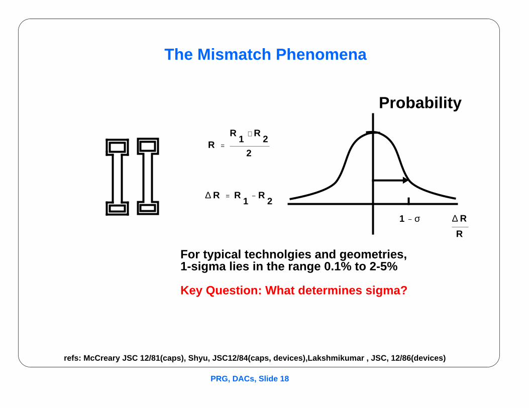
The Mismatch Phenomena
refs: McCreary JSC 12/81(caps), Shyu, JSC12/84(caps, devices),Lakshmikumar , JSC, 12/86(devices)
RR
1R
2+
2=
∆ R R1
R2
−=
Probability
1 σ− ∆ R
R
For typical technolgies and geometries,1-sigma lies in the range 0.1% to 2-5%
Key Question: What determines sigma?
PRG, DACs, Slide 19
Mismatch Effects in Binary Weighted DACs

PRG, DACs, Slide 20
Design Approaches for Improving Linearity
• Laser Trimming• Discrete trim/Poly fuse• Segmentation• Self-Calibration• Dynamic Element matching
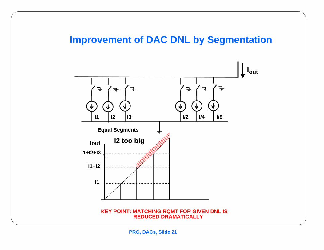
PRG, DACs, Slide 21
How do we Solve this in a DAC?
Standard Approach: Segmentation
I1 I2 I3 I/2 I/4
Equal Segments
I1
I1+I2
I1+I2+I3
I/8
KEY POINT: MATCHING RQMT FOR GIVEN DNL IS REDUCED DRAMATICALLY
I2 too big
Improvement of DAC DNL by Segmentation
Iout
Iout
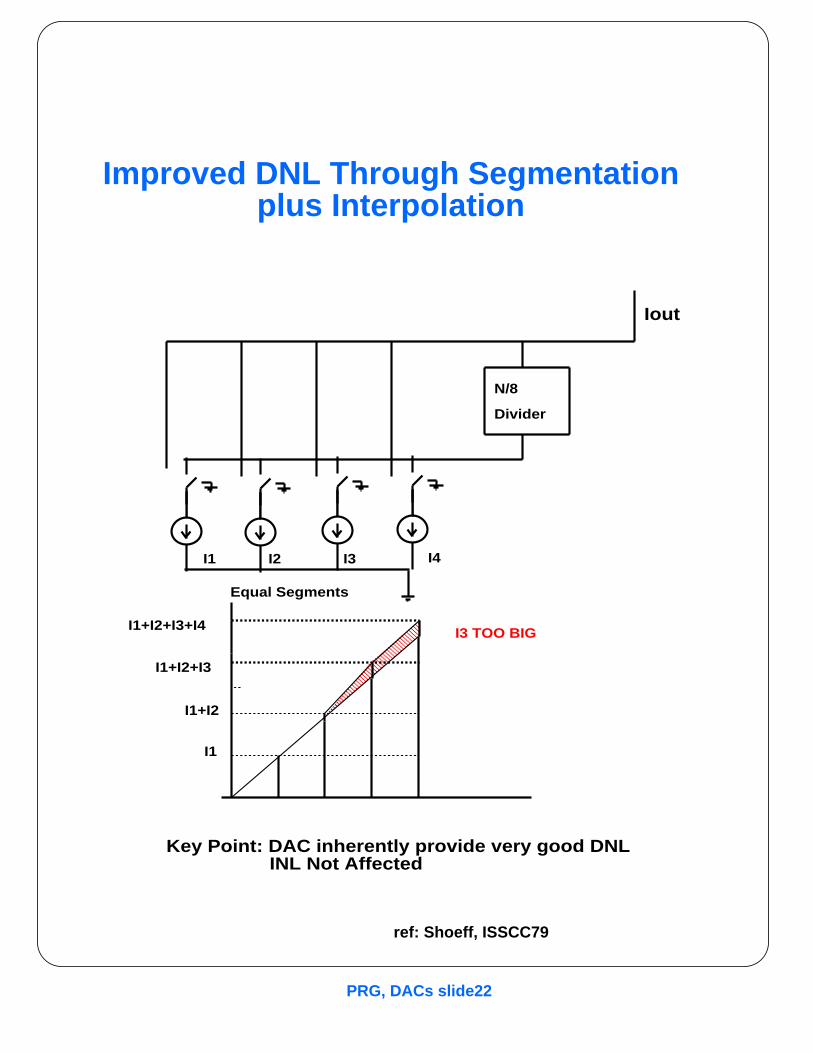
PRG, DACs slide22
I1
I1+I2
I1+I2+I3
I3 TOO BIG
Improved Approach:
Segmentation Plus Interpolation
I1 I2 I3
Equal Segments
N/8
Divider
I4
Iout
I1+I2+I3+I4
Key Point: DAC inherently provide very good DNL INL Not Affected
Improved DNL Through Segmentationplus Interpolation
ref: Shoeff, ISSCC79
PRG, DACs, Slide 23
Symp VLSI paper

PRG, DACs, Slide 24
Segmented DACs
Key Concept:• Improve DNL by building DAC Xfer characteristic out of additive equalsegments rather than binary weighted elements
Advantages:• Dramatically improves DNL
• With proper decoding can improve glitch energy
Disadvantages:• More complex switching
• Does nothing for INL
Key Design Issues:• Number of segments
• Layout, segment turnon sequence
refs: Kumazawa, VLSICkts, 1990; Nakamura, VLSIckts, 1990

PRG, DACs, Slide 25
Resistor/Capacitor Interpolation
refs: Fotouhi, JSC12/79;Tan, ISSCC83
PRG, DACs, Slide 26
Capacitor-Resistor Interpolation
Ref: Agazzi, JSC, 4/89
PRG, DACs, Slide 27
Self-Calibration of Q-R DACs

PRG, DACs, Slide 28
Self-Cal of Q-R DACS, contd
refs: Lee, Hodges, JSC, 12/84, Miller, ISSCC90, Croteau, ED, Sept86
PRG, DACs slide29
Self-Calibrated DACs
Key Concept:• Improve DNL and INL by using on-chip intelligence tomeasure and correct DAC non-linearity
Advantages:• Dramatically improves DNL, DNL
• Can compensate for environmental changes
• .Allows high-performance DAC/ADC with standardtechnology
Disadvantages:• Much more complex analog and digital circuitry
• Self-cal can be a burden to the user
.
PRG, DACs, Slide 30
Example Self-Cal Application
Single-Chip CMOS Programmable Data Acquisition System
• Uses Digital CMOS to allow higher level of integration of DAS functionin a reasonable size
• Uses self-cal to allow 13bit ADC in std CMOS
• Address application diversity throught programmability
• Uses lateral bipolar transistors and poly fuse trimming for precisionband gap.

PRG, DACs, Slide 31
Current-Replica Self-Calibration
To Calibrate Segment:
Force Iseg=Iref
Problem:• Charge Injection error
Solutions:• Big Cs
• Small switch
• Slow turnoff
• Small correction current
ref: Groenveld, ISSCC89
PRG, DACs, Slide 32
Algorithmic ADC Technique
Potential Advantages• Hardware simplicity
• Single parameter calibration
• Inherently programmable gain function
• Inherent Differential Implementation
Potential Disadvanatages• Sensitivity to Loop Offsets
• Speed limitations in Op Amp Settling
Critical Design Issues• Loop Offset Cancellation
• Loop Gain Calibration
• Op Amp Settling Time Optimization
refs: Ohara JSC 12/87, Webb ISSCC80, Li JSC12/84, Jusuf, CICC92


