132
DAILY VEHICLE RANGE BODYBUILDERS INSTRUCTIONS L I G H T R A N G E ISSUE 2007

DAILY VEHICLERANGE BODYBUILDERS INSTRUCTIONS
LIG
HT
RA
NG
E
ISSUE 2007

Publication Edited by:Technical ApplicationStrada delle Cascinette, 424/3410156 Turin - Italy
Publication Nr. 603.93.751 - 2nd EditionPrinted in Italy - 04.08
B.U. TECHNICAL PUBLISHINGIveco Technical PublicationsLungo Stura Lazio, 15/1910156 Turin - Italy
Produced by:

Print 603.93.751 Base - April 2008
Update data
DAILY 2007
Bodybuilders instructionsPrint 603.93.751 - 2nd editionBase - April 2008
UPDATE DATA
Section Description Page Revision date
2 Notes and table for tyre screwtightening added
54 February 2008
2 Under-dashboard relay fusebox
83 February 2008
2 Engine compartment relay fusebox (Euro 4 Diesel)
84 February 2008
2 Opt fuse box Enginecompartment (t.2.28/2.29)
86 February 2008
2 Engine compartment relay fusebox (CNG)
88 February 2008
2 Opt fuse box Enginecompartment (Daily CNG)
91 February 2008
4 PTO added to Daily CNGwithmanual gearbox
12 February 2008
4 PTO added to Daily CNGwithautomatic transmission
13 February 2008
A Appendix February 2008
2 Trailer KIT PN removed 95 July 2007
2 Paragraph 2.16.9 added 99 July 2007
4 Automatic gearbox sectionupdated
13 July 2007
4 Specific procedure 1 added 18, 19 July 2007
5 Figure and specific text2 changed
13 July 2007
5 Figure and specific text3 changed
14 July 2007

Base - April 2008 Print 603.93.751
Update data

This publication provides the data, features and instructions for vehicle fitting and modifications.
It is intended for qualified, skill personnel. The body builder is responsible for designing the fitting, its modification and execution,and will have to ensure compliance with the provisions both of this publication and the law regulations in force.
Prior to carrying out any work, make sure you have the publication of the vehicle model on which you are about to work. Also makesure that all the accident-prevention equipment such as, for instance, goggles, helmet, gloves, boots, etc. as well as the working, liftingand handling equipment are available and in goodworking order. Finally, make sure that you operate on the vehicle in such conditionsas to ensure maximum safety.
The execution of the work by strictly complying with the above provisions, as well as the use of the components shown, ensure thatthe work is carried out correctly and safely.
Any change, modification or fitting not covered by this manual and not expressly authorized in written by IVECO will relieve thelatter of any responsibility and make, in particular, the vehicle guarantee null and void.
IVECO is available to provide all and every explanation required to carry out the work and also help you handle the cases not dealtwith in this publication.
After every single intervention, the functioning, efficiency and safety conditions established by IVECO shall be restored. Contact theIVECO service network for vehicle set-up, if necessary.
IVECO shall not be responsible for any change, modification or fitting concerning the vehicle.
The data and information contained in this publication may not be updated due to the changes made by IVECO, at any time, fortechnical or commercial reasons, or to make the vehicles comply with the law regulations in force in the different countries.
In case of disagreement between the provisions included herein and the actual vehicle make-up, contact IVECO prior to carryingout any work.
General danger
It includes the dangers of above described signals.
Danger of serious damage for the vehicle
Partial or complete non observance of these prescriptions can cause serious damages to the vehicle and sometimesguarantee lapse too.
Environment protection
It indicates correct behaviour in order that vehicle use is environmentally friendly as much as possible.
Danger for persons
Missing or incomplete observance of these prescriptions can cause serious danger for persons’ safety.
Symbols - Warnings
!
Foreword
It indicates an additional explanation for a piece of information.NOTE
Print 603.93.751 Base - April 2008
Foreword

Page header and footer interpretation
Vehicle type Section titleSection number -page number
Printnumber
Chapter title Basic edition -month year
Base - April 2008 Print 603.93.751
Foreword

Print 603.93.751 Base - April 2008
Index of section
INDEX OF SECTION
Section
General specifications 1
Chassis modifications 2
Fitting superstructures 3
Power Take-offs 4
Specific information and instructions 5
Appendix

Base - April 2008 Print 603.93.751
Index of section

GENERAL SPECIFICATIONS 1-1DAILY 2007
Print 603.93.751 Base - April 2008
Index
Index
SECTION 1
General specifications
Page
1.1 Aim of bodybuilders instructions 1-3
1.2 IVECO approval for changes and fittings 1-3
1.3 Liabilities 1-4
1.4 Guarantees 1-4
1.5 Request for approval 1-4
1.6 IVECO technical documents available by means of computer 1-5
1.7 Trademarks and Logos 1-5
1.8 Legal Provisions 1-5
1.9 Prevention of accidents 1-6
1.10 Choice of material to use: Ecology - Recycling 1-6
1.11 Vehicle delivery 1-7
1.12 Vehicles identification 1-8
1.13 Dimensions and masses 1-9
1.13.1 General Specifications 1-9
1.13.2 Determining the Centre of Gravity of the Body and Payload 1-10
1.13.3 Observing the Permitted Weights 1-13
1.14 Instructions for the Correct Functioning of the Parts of the Vehicle and Accessibility for Maintenance 1-14
1.15 Quality System management 1-15
1.16 Vehicle maintenance 1-15
1.17 Conventions 1-16

1-2 GENERAL SPECIFICATIONS DAILY 2007
Base - April 2008 Print 603.93.751
Index

GENERAL SPECIFICATIONS 1-3DAILY 2007
Print 603.93.751 Base - April 2008
Aim of bodybuilders instructions
Aim of bodybuilders instructions
1.1 Aim of bodybuilders instructions
The purpose of this publication is to provide data, specifications and instructions for the bodybuilding and conversion of an originalIVECO vehicle to ensure the functionality, safety and reliability of the vehicle and its components.
1.2 IVECO approval for changes and fittings
Changes must be carried out in accordance with the requirements set out in the following guidelines.
The following may be carried out only with IVECO’s approval after submitting a copy of the documentation required for technicalevaluation of the proposed change (drawings, calculations, technical report etc.):
- wheelbase modifications, whereby the value of the newly obtained wheelbase does not fall within the minimum and maximumvalues available within the IVECO range for the same vehicle;
- work carried out on the braking system;
- work carried out on the suspension system;
- steering wheel modifications;
- changes to the stabiliser bars and suspensions;
- changes to the cab, cab supports, locking and tipping devices;
- changes to the engine intake and exhaust systems;
- engine cooling system modifications;
- power unit and driving component modifications;
- work carried out on front and rear axles;
- fitting decelerator brakes;
- fitting power take-offs;
- changing the tyre dimensions;
- coupling device (hooks, fifth wheels) modifications;
- electric/electronic unit modifications.
The other modifications of fittings covered by the following standards and made in compliance with the same do not require specificapproval from IVECO. Any modification or fitting not covered by these standards shall, on the contrary, be authorized by IVECOin advance.

1-4 GENERAL SPECIFICATIONS DAILY 2007
Base - April 2008 Print 603.93.751
Liabilities
Liabilities
1.3 Liabilities
The authorizations issued by IVECO concern solely the technical/conceptual feasibility of the modification and/or fitting to bemade on a genuine IVECO vehicle.The bodybuilder is responsible for the:
- project of the modification or fitting;
- choice and features of the products used;
- workmanship of the modification or fitting;
- compliance of the project and its implementation with all the instructions provided by IVECO;
- compliance of the project and its implementation with all the current regulations in the country where the vehicle is registered;
- the functionality, safety and reliability and in general the effective performance of the vehicle and also the effects that the changesand the conversion may have on vehicle performance and specifications.
1.4 Guarantees
The bodybuilder/chassis converter who has built the body or who has modified the chassis must guarantee that the work wasundertaken in a professional manner in full compliance with the specifications contained in this manual. IVECO reserves the rightto declare void its own warranties for the vehicles where:
- these specifications have not been adhered to or where unauthorised equipment was installed, or unauthorised modificationswere carried out;
- an unsuitable frame has been used for the required conversion or application;
- the specifications, standards or instructions issued by the Manufacturer for the flawless execution of the operations have notbeen heeded;
- original spare parts or components which the Manufacturer has made available for specific interventions were not used;
- read and respect the safety standards and symbols applied before any operation;- do not use the vehicle for applications other than those for which it is designed.
Maintaining the functionality of vehicle components.The effective operation of vehicle components, all component safety and running conditions, com-pliance with national and international regulations (e.g. EC Directives) and also accident preventionstandards must naturally be guaranteed in all permitted conversions and applications.All our vehicles are covered by a warranty as laid down in the specific documents.The bodybuilder must arrange to carry out operations at least in an equivalent manner.
1.5 Request for approval
The requests for approval or support to carry out work ormake modifications or fittings shall be forwarded to the IVECOmarke-ting offices in charge.
To obtain the approval, the body builder shall provide adequate documents that illustrate the anticipated implementation, utilizationand conditions of use on the vehicle. The drawings shall highlight any item differing from the instructions contained in this manual.
The body builder shall submit the modification and/or fitting to the competent authorities for approval.

GENERAL SPECIFICATIONS 1-5DAILY 2007
Print 603.93.751 Base - April 2008
IVECO technical documents available by means of computer
IVECO technical documents available by means of computer
1.6 IVECO technical documents available by means of computer
The following technical documents are available on the Internet at www.thbiveco.com:
- directives for transformation and equipping of vehicles;
- technical cards;
- chassis cab diagrams;
- chassis diagrams;
- other specifications concerning the vehicle range.
The body builder shall submit the modification and/or fitting to the competent authorities for approval.
1.7 Trademarks and Logos
Trademarks, nameplates and denominations must not be modified or displaced in relation to the original design. The appearanceof the vehicle must not be changed or modified.
The application of trademarks tied to the transformation or trim levels must be authorised by IVECO. They must not be appliednear to the IVECO tradenames or logos.
IVECO reserves the right to withdraw the tradenames and logos if the fitting or conversion fails to conform with requirements. Thebodybuilder accepts all responsibility for the entire vehicle.
Instruction for added assemblies
Where assemblies are added, the bodybuildermust provide the necessary service andmaintenance instructions when the vehicleis delivered.
1.8 Legal Provisions
On completing the vehicle, the bodybuilder/chassis converter must check the work (modifications, body + equipment etc.) toensure that the legal provisions required in the country of registration are observed (e.g. weights, dimensions, braking, noise,emissions etc.). Information regarding these matters may be obtained from the competent Authorities or the IVECOAreaNetwork.
The vehiclesmanufactured at our plant (except some versions for Extra-European countries) comply with the EC directives. Conver-ted vehicles must also comply with these directives. The only permissible exception is granted where local type approval differs fromEC homologation.

1-6 GENERAL SPECIFICATIONS DAILY 2007
Base - April 2008 Print 603.93.751
Prevention of accidents
Prevention of accidents
1.9 Prevention of accidents
Do no allow unauthorised personnel to work on or operate the vehicle.
It is forbidden to use the vehicle if its safety devices have been tampered with or damaged.
The structures and devices fitted to the vehiclesmust complywith the current regulations concerningthe prevention of accidents and safety regulations in force in the countries where the vehicle is to beused.
All the precautions dictated by technical awareness must be adopted to prevent malfunction and functional defects.
Compliance with these regulations will be the responsibility of the manufacturers of the structures and devices.
!Components such as seats, coverings, linings, protective panels etc.may represent a potential fire haz-ard if they are exposed to an intense heat source.
Arrange for their removal before working with welding equipment and flames.
1.10 Choice of material to use: Ecology - Recycling
Increasingly greater attention should be paid, at the study and design stage, to the choice of materials to be used.
This is especially the case as regards the aspects connected with ecology and recycling in the light of domestic and internationalregulations that are constantly being developed in the sector.
In this connection:
- everyonemust be aware of the prohibitions on using harmful or potentially hazardousmaterials, such as ones containing asbestos,lead, halogen additives, fluorocarbons, cadmium, mercury, hexavalent chrome, etc.
- Use materials whose processing produces limited waste and that permit easy recycling after their first use.
- With composite synthetic materials, use components that are compatible with each other, envisaging also their possible utiliz-ation with the addition of other salvaged components. Affix the markings required in compliance with the current regulations.
- Batteries contain substances that are very hazardous to the environment. When replacing batteries, we advise contacting theservice network, which is suitably equipped for battery disposal in compliance with environmental policies and laws.
In order to comply with EC directive 2000/53 (ELVs), IVECO S.p.A. prohibits fitting parts containinglead, mercury, cadmium and hexavalent chrome to vehicles (except for the departures referred to inAttachment II of the above directive).

GENERAL SPECIFICATIONS 1-7DAILY 2007
Print 603.93.751 Base - April 2008
Vehicle delivery
Vehicle delivery
1.11 Vehicle delivery
Prior to delivering the vehicle, the body builder shall:
- verify that the work has been made correctly;
- perform vehicle and/or equipment set-up;
- check the operation and safety of the vehicle and/or equipment;
- prepare and deliver the necessary instructions for service andmaintenance of the fitting and any additional units to the end custo-mer;
- write the new data down on the special tags;
- confirm that the work carried out complies with the indications provided by the vehicle manufacturer and with the law regula-tions;
- carry out the checks included in the ”IVECO Pre-Delivery inspection” list (available from the IVECO network) with regard tothe items affected by the work done;
- provide a guarantee for the modifications made;
- in the event that the connections originally provided with screws have been mounted and restored, the same screws shall notbe used. In such an instance, and in the event that nails have been replaced with screws, you must check again the closing ofthe connection after travelling approximately 500-1000 km.
- measure the battery voltage. Ensure there is a minimum charge of 12.5 V. If the voltage reading is between 12.1 and 12.49 V,recharge the battery (slow charge). If the voltage is less than 12.1 V, the battery must be scrapped and replaced with a new one;
- the batteries must be serviced at regular intervals until the vehicle is handed over to the customer to prevent problems of lowcharge, short-circuits or corrosion. IVECO reserves the right to terminate the battery warranty if the maintenance proceduresrequired by the IVECO network are not observed.

1-8 GENERAL SPECIFICATIONS DAILY 2007
Base - April 2008 Print 603.93.751
Vehicles identification
Vehicles identification
1.12 Vehicles identification
The commercial designation of IVECO vehicles is not the same as the type approval (homologation) designation. Two typesof commercial designation are shown below with the meaning of the codes used:
GVW(tx10)
Class Enginerating(HP:10)
Version Suspension
2 9 L 1 0
3 5 S 1 2 D - P
5 0 C 1 5 C N G - P
Class Rear wheels GVW (t) VersionL single 2.8 — 3.3 - TruckS single 3.5 V VanC twin 3.5 — 6.5 D Crewcab 6+1
CNG CNG engine
Suspension- mechanic/P pneumatic

GENERAL SPECIFICATIONS 1-9DAILY 2007
Print 603.93.751 Base - April 2008
Dimensions and masses
Dimensions and masses
1.13 Dimensions and masses
1.13.1 General Specifications
The dimensions and maximum permissible weight on the axles are indicated on the bodybuilder layout drawings, on technicalspecification sheets and, in greater details, on the official documentation issued by the Company. The kerb weights refer to vehicleswith standard equipment. Special equipment may involve considerable modification to the weight and its distribution on the axles.
On our vehicles, lights and rear-view mirrors are designed for widths of up to 2350 mm.
Weighing the Chassis
As a result of production factors there could be at a ±5% variation in the published weights for models 29L, 35S and 35C anda ±3% for models 40C, 50C, 60C and 65C.
It is therefore, advisable to weigh the vehicle in the chassis cab condition before fitting the body and equipment and establish theweight distribution on the axles.
Body conversions
The body building limits for each model are mainly defined by the following:
- weight distribution on the axles;
- width of the mirrors used;
- position of the rear under run-bar.
Greater values in compliancewith theweights permitted on the axlesmay be authorized by IVECO aftermodifying such componentsas the chassis, under run-bar, mirrors, etc.

1-10 GENERAL SPECIFICATIONS DAILY 2007
Base - April 2008 Print 603.93.751
Dimensions and masses
1.13.2 Determining the Centre of Gravity of the Body and Payload
Positioning on the longitudinal plane
To establish the location of the centre of gravity of the body and payload the following examples belowmay be used as guidelines.
The technical documentation specific to eachmodel (chassis cab drawing) give the positions permittedwith the vehicle in its standardform. The masses and positioning of the single components of the vehicle are given in the chassis and weight distribution diagram.
respectively L1 = L − W2 ⋅ LW
102452
Figure 1.1
W = Body + payload (kg)
W1 = Body and payload acting on front axle (kg)
W2 = Body and payload acting on rear axle (kg)
L1 = Distance of the centre of gravity from the rear axle centre line (mm)
L = Wheelbase (mm)
L1 =W1 ⋅ LW
Example of calculation of the load barycentre positionConsider a 40C15 vehicle with a wheelbase of 3,450 mm with:
1. GWW= 4,200 kg (permitted maximum: 1,900 kg on the front and 3,100 kg on the rear)
2. KERB WEIGHT = 1,955 kg (1,340 kg on the front axle, 615 kg on the rear)
The permitted maximum load (body + payload) will beW= 4,200 - 1,955 = 2,245 kg. Let us calculate the position of the centerof gravity in which the maximum permitted on the front axle is achieved. Let us assume an uniform distributed load .
In this case, out of 2,245 kg. W1 = 1,900 - 1,340 = 560 kg will affect the front axle, while the remainingW2 = 2,245 - 560 = 1,685kg will affect the rear axle.
Thus, the following will be obtained:
1. W1 = 560 kg
2. L = 3450 mm
3. W = 2245 kg
L1= W1 x L / W = 860 mm
The center of gravity of the load (Body + payload) must not be more than 860 mm far from the rear axle; otherwise, the frontaxle would be overloaded.

GENERAL SPECIFICATIONS 1-11DAILY 2007
Print 603.93.751 Base - April 2008
Dimensions and masses
In order to determine the payload on the axles, it must be uniformly distributed except when the shape of the loading surface itselfentails a different distribution of the load.
Regarding any equipment, the actual position of the centre of gravity must be used.
When building bodies or containers, loading and unloading systems must be devised which preclude excessive variations in thedistribution of the load and/or excessive loads on the axles. Relevant instructions should also be given to the operator.
Uniform load distribution Uneven load distribution
Uniform load distribution Uneven load distribution(beware of axle loads and minimum axle ratio)
102453
Figure 1.2
Figure 1.3

1-12 GENERAL SPECIFICATIONS DAILY 2007
Base - April 2008 Print 603.93.751
Dimensions and masses
Height of centre of gravity
The height of the centre of gravity of the chassis cab is given in the technical documentation specific to each model (chassisdrawing).
For testing the vehicle complete with superstructure, the bodybuilder must check that the height of the centre of gravity of theequipment including the payload, or of the entire vehicle when fully loaded, falls within the maximum permitted values.
These limits are defined in compliancewith the national or international regulations (e.g. ECDirective regarding braking) or requestedby the Manufacturer to ensure good handling of the vehicle (e.g. transverse stability of the moving vehicle).
102454
Ht=Wc . Hc + Wb . HbWc + Wb
Hb= (Wc + Wb) . Ht − Wc . Hc
Wb
Wc = Chassis cab vehicle kerb weight
Hc = Height of centre of gravity of chassis cab vehicle (laden condition)
Wb = Body and payload
Hb = Height of centre of gravity of body and payload in relation to ground
Wt = Vehicle weight when fully loaded
Ht = Height of centre of gravity of vehicle with full load
Figure 1.4
Verification with full load:
To check the vehicle with its body but no payload, use the above formula but for Wb use only the vehicle unladen weight (Theposition for Hc will depend on the load and deflection of the suspension).
The height of the centre of gravity indicated in Table 2.6 represents values which are not to be exceeded for each given equipmentlevel. These values have been calculated only in terms of the transverse stability of the vehicle and are applicable to a mid wheelbase.Any other possible restrictive specification, e.g. braking regulation, should be taken into consideration.
The values given in Table 2.6 refer to the body with fixed payload. In versions where the payload tends to move sideways (e.g.suspended loads, fluid loads etc.) especially when turning, higher dynamic transverse forces is generated which makes the vehicleless stable. This must be taken into consideration when providing vehicle operating instructions or for possible reduction in theheight of the centre of gravity.

GENERAL SPECIFICATIONS 1-13DAILY 2007
Print 603.93.751 Base - April 2008
Dimensions and masses
Using Stabiliser BarsSupplementary stabilising or anti-roll bars, where available, spring reinforcements or the application of rubber components (in
compliance with point 2.11) may increase the height of the centre of gravity of the payload which must be defined as each occasionarises. The modification must be carried out after careful consideration has been given to the specifications of the body type, tothewheelbase and to the distribution of the transverse forces acting on the suspension both at the front and at the rear of the vehicle.Modification to the front axle may be made where the load is positioned behind the cab (e.g. crane) or where the body is very rigid(e.g. van conversion).
1.13.3 Observing the Permitted Weights
All the limits specified on the IVECO documents must be complied with. It is essential that the maximum weight on the frontaxle is not exceeded, under any load condition, so as to ensure the correct steering and braking characteristics regardless of theroad surface conditions.
Particular attention must be taken with vehicles where the load is concentrated on the rear overhang (e.g. cranes, tail lifts, trailers)and to vehicles with short wheelbases and a very high centre of gravity.
Ensure transverse loads are properly distributed when positioning auxiliary components and superstructures. A +4% variation onthe rated load (50% of load on the axle) is permissible for each wheel (for example: permissible load on axle 3000 kg; 1440 to 1560kg allowed for each wheel side); in compliance with load allowed by tyres, without affecting braking properties and vehicle drivingstability.
Apart from different specifications for specific vehicles, the following may be taken to be the minimum weights for the front axle:30% of the total vehicle weight (with uniformly distributed loads and with loads concentrated on the rear overhang).
The rear overhang of the body must be built in strict observance of the permitted axle loads, the minimum load required on thefront axle, the limitations in length, the positioning of any tow hook and of the rear under-run guard stipulated by the relevantNational and EC regulations.
Variations in the Permissible Weight
Special exceptions to the maximum permissible weights may be granted for particular applications for which, however, preciselimitations regarding the use will be imposed in addition to possible vehicle reinforcements.
Such exemptions, if they exceed the limits imposed by law, must be authorised by the Government Administrative Authority.
The request for authorisation must include:
- vehicle type, wheelbase, identification number, designated use;
- unladen weight on the axles (e.g. vehicles equipped with crane) including positions for the centre of gravity of the payload;
- proposals concerning the reinforcement of the vehicle components where necessary.
The reduction in the permissible weight on the vehicle (derating) may involve changing various components such as suspension,brakes etc) and may require recalibration of the load sensing valve where one is fitted. In these circumstances necessary instructionsmay be provided.

1-14 GENERAL SPECIFICATIONS DAILY 2007
Base - April 2008 Print 603.93.751
Instructions for the Correct Functioning of the Parts of the Vehicle and Accessibility for Maintenance
Instructions for the Correct Functioning of the Parts of the Vehicle and Accessibility for Maintenance
1.14 Instructions for the Correct Functioning of the Parts of the Vehicleand Accessibility for Maintenance
As a rule, when modifying or installing any type of equipment, nothing must be altered which prevents the correct functioningof assemblies and parts of the vehicle under all operational conditions.
For example:
- Ready access to all parts requiring inspection or maintenance and periodic servicing must be provided. In the case of closed bodytypes suitable opening doors must be provided.
- Service access to chassis/driveline components must be retained. For instance repairing the gearbox or clutch must be possiblewithout necessitating the removal of major components of the added structure.
- The cooling system (radiator cowling, radiator, air passages, cooling circuit etc.), fuel supply (pump position, filters, pipe diameter,etc.) and the engine air intake must not be altered.
- The anti-noise panels must not be altered or moved in order to prevent changes in the approved noise levels of the vehicle.Should it be necessary to make openings (e.g. for the longitudinal runner of the body to pass through) these must be properlyclosed off using material with inflammability and soundproofing characteristics equivalent to those used originally.
- Adequate ventilation of the brakes and battery case (especially in the case of vans) must be guaranteed.
- When positioning the mudguards and wheel arches, the rear wheels must be free to rebound even when used with chains.
- When the vehicle has been set up, for safety reasons, headlight attitude must be checked and adjusted as necessary. Performthe adjustment according to the instructions provided in the use and maintenance manual.
- In the case of parts which are supplied loose (e.g. spare wheel, chocks) it will be the responsibility of the bodybuilder to positionand secure them in an accessible and safe manner in compliance with possible national laws.
GENERAL SPECIFICATIONS 1-15DAILY 2007
Print 603.93.751 Base - April 2008
1.15 Quality System management
For some time IVECO has been promoting Quality System development and training for bodybuilders.
This is a requirement due not only to compliancewith domestic and international regulations on product liability, but also the growingdemand for increasingly higher quality levels. The creation of new forms of organization in the various sectors and the quest forincreasingly more advanced levels of efficiency.
IVECO believes it essential for bodybuilders to be equipped with an organization where the following are defined and available:
- Organization charts for functions and responsibilities.
- Quality system.
- Quality goals.
- Technical design documentation.
- Process and control phases with relevant resources.
- Product improvement plan, obtained also with corrective actions.
- After sales service.
- Staff training.
- Manufacturer liability documentation.
1.16 Vehicle maintenance
In addition to making the necessary checks on the outfit in keeping with customary working procedures, the bodybuilder shallperform the checks specified in the “IVECO pre-delivery inspection” list, which can be obtained from the IVECO network, for theaspects affected by the modifications performed.

1-16 GENERAL SPECIFICATIONS DAILY 2007
Base - April 2008 Print 603.93.751
Convention
Convention
1.17 Conventions
In these bodybuilders instructions, the wheelbase is taken as the distance between the centreline of the first steering axle andthe centreline of the first rear axle (driven or non-driven). This definition differs from the definition of wheelbase in the CEDirectives.The rear overhang is taken as the distance between centreline of the last axle and the rear end of the chassis runner. For dimensionsA, B and t of the frame and counterframe section please refer to the figure below.
Figure 1.5
91473

CHASSIS MODIFICATIONS 2-1DAILY 2007
Print 603.93.751 Base - April 2008
Index
Index
SECTION 2
Chassis modificationsPage
2.1 General instructions for chassis modifications 2-5
2.1.1 Specific Precautions 2-5
2.2 Protection against Rust and Painting 2-7
2.2.1 Original components 2-7
2.2.2 Added or modified painted parts 2-10
2.2.3 Precautions 2-11
2.2.4 Exceeding the Limits 2-12
2.3 Drilling the Chassis 2-13
2.3.1 Screws and nuts 2-13
2.3.2 Characteristics of the material to be used when modifying the chassis 2-14
2.3.3 Stresses on the chassis 2-15
2.3.4 Welding the Chassis 2-16
2.3.5 Closing of existing holes 2-18
2.4 Modifying the Wheelbase 2-19
2.4.1 General Specifications 2-19
2.4.2 Authorisation 2-19
2.4.3 Consequences for steering 2-19
2.4.4 Effect on Braking 2-20
2.4.5 Consequences for steering 2-20
2.4.6 Chassis Stress Level 2-21
2.4.7 Cross Members 2-21
2.4.8 Chassis reinforcements 2-22
2.4.9 Changes to transmissions 2-22
2.5 Modifying the Rear Overhang 2-23
2.5.1 General Specifications 2-23
2.5.2 Authorisation 2-23
2.5.3 Reducing the Overhang 2-23
2.5.4 Increasing the Overhang 2-23

2-2 CHASSIS MODIFICATIONS DAILY 2007
Base - April 2008 Print 603.93.751
Index
Page
2.6 Installing a Towing Device 2-25
2.6.1 General Specifications 2-25
2.6.2 Traditional towing hooks 2-26
2.6.3 Hook types 2-29
2.6.4 Lowered Rear Cross Member 2-29
2.7 Installing a Supplementary Axle 2-31
2.8 Modifying the Drive Line 2-31
2.8.1 Permitted lengths 2-31
2.8.2 Determining Driveshaft Positions 2-34
2.9 Modifications of the Engine Cooling System 2-37
2.9.1 Intake 2-37
2.9.2 Engine exhaust 2-37
2.10 Modification of the Engine Cooling System 2-38
2.11 Work on the Suspension 2-39
2.12 Heating/Air conditioning system modifications 2-41
2.12.1 Installation of a Supplementary Heating System 2-41
2.12.2 Installing an Air-Conditioning System 2-42
2.13 Cab Modifications 2-43
2.13.1 General Specifications 2-43
2.13.2 Roof Panel Modifications 2-44
2.13.3 Van and combi bodywork modifications 2-46
2.13.4 Crew Cabs 2-52
2.13.5 Occupant protection 2-53
2.14 Changing the Size of the Tyres 2-54
2.15 Modifications to the Braking System 2-55
2.15.1 General remarks 2-55
2.15.2 Brake pipes 2-55
2.15.3 Fitting pipes on the vehicle 2-57
2.15.4 Instructions for adjusting the braking load proportioning valve 2-60
2.15.5 ESP (Electronic stability control) 2-62

CHASSIS MODIFICATIONS 2-3DAILY 2007
Print 603.93.751 Base - April 2008
Index
Page
2.16 Electrical System: Modifications and Drawing-Off Power 2-63
2.16.1 Earth points 2-65
2.16.2 Electromagnetic compatibility 2-70
2.16.3 Additional equipment 2-77
2.16.4 Current drawing 2-80
2.16.5 Additional Circuits 2-94
2.16.6 Harness Modifications due to Changes to Wheelbase or Overhang 2-95
2.16.7 Provision for trailer 2-95
2.16.8 Side Marker Lights 2-98
2.16.9 Operation of emergency control on dashboard (option) 2-99
2.17 Repositioning Parts and Mounting Auxiliary Assemblies and Equipment 2-101
2.18 Retarder Installation 2-104
2.19 Modifications to the Rear Underrun 2-105
2.20 Rear mudguards and wheel boxes 2-106
2.21 Mudflaps 2-106
2.22 Side Guards 2-107
2.23 Chocks 2-108

2-4 CHASSIS MODIFICATIONS DAILY 2007
Base - April 2008 Print 603.93.751
Index

CHASSIS MODIFICATIONS 2-5DAILY 2007
Print 603.93.751 Base - April 2008
General instructions for chassis modifications
2222.2
General instructions for chassis modifications
2.1 General instructions for chassis modifications
Particular attention must be given to the following points:
- Welding to the bearing structures of the chassis is explicitly prohibited (with the exception of the items described at points2.3.4, 2.4 e 2.5);
- Holes in the flanges of the side members are not permitted (except for the items described at point 2.3.4);
- Where riveted connections exist and can be modified as explained below, these can be replaced by flanged-head screws andnuts of min. class 8.8 or by hex screws of the next greater diameter and self locking nuts. Screws greater than M14 must notbe used (max. diameter of hole 13 mm) unless otherwise specified.
- In cases where the original joints were detached and rejoined with bolts it is forbidden to reuse the same bolts. In this eventand when rivets are replaced with bolts, the bolt torque must be checked after the vehicle has been driven approximately 500÷ 1.000 kms.
2.1.1 Specific Precautions
!During the welding, drilling, grinding and cutting operations when working in the proximityof brake lines and particularly if these are of plastic material or electric wiring, care must betaken to ensure their protection.Where necessary they should be removed (complywith theprovisions given at points 2.15 and 2.16).
Figure 2.1
91444

2-6 CHASSIS MODIFICATIONS DAILY 2007
Base - April 2008 Print 603.93.751
General instructions for chassis modifications
Regarding the electrical equipment remember to:a) Take precautions concerning the alternator and the electrical/electronic components. In order to avoid damaging the diode
rectifier, never disconnect the batteries (or open the isolator) when the engine is running.If the vehicle has to be tow started make certain that the batteries are connected. Should it be necessary to quick chargethe batteries, disconnect them from the vehicle circuit.In order to run the engine with external means and in order to avoid current peaks which might damage the electric/elec-tronic components, do not use the ”start” function in conjunction with external charge devices if such devices are equippedwith this function. Starting will have to be carried out only with the external battery trolley ensuring correct polarity.
b) Checking the earth connections.As a general rule the original earth connections of the vehicle must not be changed. If it is necessary to move these connec-tions or to implement further earth points use the existing holes on the chassis as far as possible and:
- Remove, mechanically, and/or with an appropriate chemical product, the paint on the chassis side and on the terminal sidecreating a resting plane free from indentations or ridges.
- Apply appropriate high conductivity paint between the cable terminal and the metal surface (e.g. galvanizing paint IVECOPart number 459622 by PPG).
- connect the earth after waiting long enough for the paint to dry.
Do not use the IVECO standardised M1 (battery earth connection) M2, M8 (earth connection for starter motor depending on thedriving position) points for the earth connections for control switches (e.g. sensors or low absorption devices): See IVECOWork-shop manuals.
With regard to the electronic devices, avoid linking earth connections between the devices; only use singlewire earths with optimisedlengths (as short as possible).
c) Electric wiring
For further information regarding the braking and electronic system, refer to point 2.15 and 2.16.

CHASSIS MODIFICATIONS 2-7DAILY 2007
Print 603.93.751 Base - April 2008
Protection against Rust and Painting
Protection against Rust and Painting
2.2 Protection against Rust and Painting
All parts fitted to the framemust be painted in accordancewith Iveco St. Iveco 18-1600 Colour IC444RAL 7021 70/80 gloss.
NOTE
2.2.1 Original components
In Table 2.1 details the operations for protecting and painting the components of the original vehicle (Table 2.3 for painted parts,Table 2.2 for non-painted or aluminium parts).
Table 2.1 - Protection category - STD 18 - 1600 (Schedule I)
Class Parts requirements Specific examples affected
A Parts in direct contact with atmospheric agents.
Body - Door mirrors - Windscreenwipers - Aerodynamickit metal structure - sun blind metal structure - Metalbumpers - Cab attachment lock - Door stopdevice - Bodyfasteners (screws,bolts, nuts, washers), etc.
BB2 Parts in direct contact with atmospheric agents.with
mainly structural characteristicsin direct view.
Frame and parts, includingfasteners.Parts beneath grille (category B).Exterior cab steps.
B1mainly structural characteristicsin direct view.
Only for rear axles and axles
CParts in direct contact with atmospheric agents.not indirect view.
Engine and parts
D Parts not in direct contact with atmospheric agents.Pedals - Seat reinforcements - Fasteners - etc., fitted insidecab.
Parts must be supplied only with cataphoretic coating or rustproofing (Schedule III). The enamelwillbe appliedduring the frame finishing stage.
NOTE

2-8 CHASSIS MODIFICATIONS DAILY 2007
Base - April 2008 Print 603.93.751
Protection against Rust and Painting
Table 2.2 - Various unpainted and aluminium parts and components - STD 18 - 1600 (Schedule IV)
Type of protection IVECO ClassType of protection IVECO
standard A B - B1 - B2 C D
Stainless steel¡ 18-0506 yes - - -
DAC 320-8yes
- - -
DAC 500-8yes
- -
DacrometDAC 320-5
18 1101-
yes- -
Dacromet(H) DAC 500-5 18-1101 -
yes- -( )
DAC 500-5 PL -yes
Category B1wheel studs
GEO321-8-PM
yes -
GEO 321-5
Geomet(HHH)
GEO321-5-PM
18-1101-
yes- -
GEO321-5-PL
-yes
Category B1wheel studs
Fe/Zn 12 III(yellow)
- - yes yes
Fe/Zn 12 V(olive green)
- - -
Zinc coating(H)
Fe/Zn 25 V(olive green)
18 1102
-
yes
- -
Fe/Zn 12 III S(yellow)
18-1102-
yes- -
Fe/Zn 12 V S(olive green)
- - -
Zinc coating FE/ZN 12 II - - yes yesZinc coating(HH) FE/ZN 12 IV S - yes - -
Aluminium
Anodicoxidation
18-1148 yes
yes yes yesAluminiumPainting
SeeSchedule III
yesyes yes yes
(H) Hexavalent chromium coatings.(HH) Hexavalent chromium-free coatings.(HHH) Chromium-free coatings.¡ Matching with other metals must not generate battery effects.

CHASSIS MODIFICATIONS 2-9DAILY 2007
Print 603.93.751 Base - April 2008
Protection against Rust and Painting
Table 2.3 - Painted parts - STD 18 - 1600 (Schedule III)
Description of the cycle phaseClasses
Description of the cycle phaseA B§ B1¤ B2 C D
MECHANICAL CLEANINGSanding/sandblasting -
MECHANICAL CLEANINGSUPERFICIAL¡
Brushingyes L
yes L - yes L yes L yes LSUPERFICIAL¡
Sandpaperingyes L
PRETREATMENT
Iron phosphatation (only fornon-precoated ferrous materials)
-yes L - yes L yes L yes LPRETREATMENT
Zinc phosphatation l yesyes L yes L yes L yes L
High thickness (30-40 μm) yes©L
yes LL
CATAPHORESIS Medium thickness (20-30 μm) yes¢yes L¥
-yes L¥ yes L
¨yes L
Acrylic top coat (>35 μm) -¥
-¨
RUSTPROOFINGDual component (30-40 μm) yes - yes yes L
yes LRUSTPROOFINGSingle component (30-40 μm)
-- yes yes
yes L¨
yes L
CHIP-RESISTANT PRIMERSingle (130 °C)or dual component (30-40 μm)
yes¢ - - - - -
Single (130 °C)or dual component (30-40 μm)
yesyes L -
LENAMEL Powder (40-110 μm) yes£
yes L- yes L
yes L¦
Single component, low temperature(30-40 μm)
- - yes
¦
¡ = Carry out operation in presence of shearing burrs, oxidation, welding swarf, laser-cut surfaces.© = Two-coat body cycle.¢ = Three-coat body cycle.£ = As an alternative to single or dual component enamel only for body parts (windscreen wipers. Rear view mirrors etc.).¤ = Only for rear axles and axles.¥ = Excluding parts that cannot be submerged in pretreatment or paint baths because this would affect their operation (e.g.: mechanical parts).¦ = Colour is specified on the drawing by means of an IC§ = For fuel tanks in ferrous sheet metal or precoated.¨ = Only parts to be fitted on engine. = Parts that cannot be treated with cataphoresis (see¥).l = For galvanised or aluminium panels, use special phosphating treatments.L = Alternative products and cycles for the same class, as long as they are compatible with the part being treated.

2-10 CHASSIS MODIFICATIONS DAILY 2007
Base - April 2008 Print 603.93.751
Protection against Rust and Painting
2.2.2 Added or modified painted parts
All parts of the vehicle (cab, chassis, bodywork, etc.) which are added or subjected to modification must be protected from rustand corrosion.
There must be no unprotected areas on ferrous materials.
Table 2.4 (painted) and Table 2.5 (unpainted) show the minimum treatments required for modified or added components whenit is not possible to provide the same protection as that used on IVECO original components. Different treatments are allowedon condition that the same level of protection against rust and corrosion is guaranteed.
Never use powder enamels directly after degreasing.
Parts in light alloy, brass and copper must not be protected.
Table 2.4 - Added or modified painted parts
Description of the cycle phaseClass
Description of the cycle phaseA - B - D (1)
Mechanical surface cleaning (including the removal of burrs / rustMechanical surface cleaning (including the removal of burrs / rustand cleaning of modified parts)
Brushing/sanding/sand blastingand cleaning of modified parts)
Brushing/sanding/sand blasting
Pre-treatment Degreasing
Anti-rust Bicomponent (30-40μm) (2)
Paint Bicomponent (30-40μm) (3)
(1) = Modifications to rear axles, front axles and engine (Classes B1 and C) are not allowed.(2) = Preferably epoxy.(3) = Preferably polyurethane.
Table 2.5 - Added or modified unpainted and/or aluminium parts
Type of protectionClass
Type of protectionA — B (1) D
Stainless steelyes
-
Dacromet (1)yes
-
Zinc treatment (1) - yes
(1) = Hexavalent chromium-free.

CHASSIS MODIFICATIONS 2-11DAILY 2007
Print 603.93.751 Base - April 2008
Protection against Rust and Painting
2.2.3 Precautions
Suitable precautions must be taken to protect those parts whose preservation and operation could be damaged by paints suchas:
- rubber or plastic pipes for the air and hydraulic installations;
- gaskets, parts in rubber or plastic;
- flanges of the transmission shafts or power take-offs;
- radiators;
- shock absorber and hydraulic or air cylinder rods;
- drainage and bleeder valves (mechanical components, air tanks, cold starting heater plug pre-heating tanks etc.);
- fuel sediment filter;
- nameplates and logos.
With particular regard to the engine and its electric and electronic components, adequate precautions shall be taken to protect:
- on the whole engine and vehicle wiring, including earth contacts;
- on all connectors on sensor/actuator side and wiring side;
- on all sensors/actuators, on flywheel, on flywheel rev sensor bracket;
- on the whole diesel fuel system pipes (plastic and metallic);
- on complete diesel fuel filter base;
- on control unit and control unit base;
- on the whole soundproofing cover inner side (injectors, rail, pipes);
- on common rail pump including regulator;
- on vehicle electric pump;
- on tank;
- on front belt circuit and relevant pulleys;
- on power steering pump and relevant piping.
If the wheels are removed, protect the contact surfaces on the hubs, avoid increasing the thickness and especially avoid the build-upof paint on the connecting flanges of the wheel disks and resting points of the fixing nuts.
Ensure that the disc brakes are adequately protected.
The electronic components and modules must be removed.
!When the painting operation is to be completedby ovendrying (max. temp. 80ºC), all parts whichmaybe damaged by exposure to heat, must be removed.

2-12 CHASSIS MODIFICATIONS DAILY 2007
Base - April 2008 Print 603.93.751
Protection against Rust and Painting
2.2.4 Exceeding the Limits
In case of special transport with considerable high centre of gravity (e.g. special body versions, advertising vehicles, etc.), froma technical point the values shown in the table may be exceeded, provided the vehicle is driven carefully (e.g. low speed, gradualrunning direction changes, etc.).
Table 2.6 - Maximum heights in relation to the centre of gravity of the payload and cornering stability
ModelsMax. height (approx.) of centre of gravity of payload(include. body and equipment) in relation to the
ground (mm)
29 L 1400
35 S 1500
35 C (front transverse leaf) 1800
35 C (front longitudinal bar) 1900
40 C 1900
45 C 1950
50 C 1950
60 C 2050
65 C 2050

CHASSIS MODIFICATIONS 2-13DAILY 2007
Print 603.93.751 Base - April 2008
Drilling the Chassis
Drilling the Chassis
2.3 Drilling the Chassis
When it is necessary to mount assemblies or auxiliary units on the chassis, as a general rule, the existing holes made at the factoryshould be used.Under no circumstances should the flanges of the supporting member of the vehicle be drilled unless in compliance with
the indications given in point 3.3.1.
In those cases (installation of shelves, brackets etc.) where it is necessary to drill new holes, they must be drilled on the verticalweb of the side member and must be carefully deburred and reamed.
Position and Size
The new holes must not be made in areas of high stress (such as supports for springs) and at variance with the cross-sectionof the side member.
The diameter of the holes must be proportional to the thickness of the steel. Under no circumstances must this exceed 13 mmunless otherwise specified. The distance from the centre of the hole to the edges of the side member must not be below 30 mm.The centres of the holes must never be located at a distance of less than 30 mm from each other or in relation to the existing holes.The holes must be staggered as shown in Figure 2.2.When moving spring or crossbeam supports, always maintain the original boringdiagrams.
Figure 2.2
102420
2.3.1 Screws and nuts
In general, use connectors of the same type and class as those for similar fixings on the original vehicle (Table 2.7).
As a general rule, materials of class 8.8 are recommended. Class 8.8 and 10.9 screws must have been hardened and tempered. Forapplications of diameter ± 6mm, stainless steel parts are recommended. Approved finishes are Dacromet and zinc coating, as detailedin Table 2.2. A Dacromet finish is not recommended if the screws are to be subjected to welding. If space allows, use screws andnuts with flanged heads. Use self-locking nuts. Nuts must be tightened using a torque wrench set to the correct torque setting forthe fixing.
2-14 CHASSIS MODIFICATIONS DAILY 2007
Base - April 2008 Print 603.93.751
Drilling the Chassis
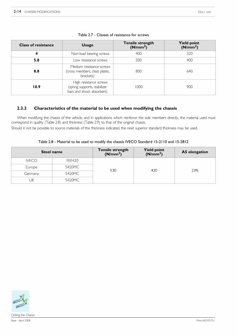
Table 2.7 - Classes of resistance for screws
Class of resistance Usage Tensile strength(N/mm2)
Yield point(N/mm2)
4 Non-load bearing screws 400 320
5.8 Low resistance screws 500 400
8.8Medium resistance screws
(cross members, cleat plates,brackets)
800 640
10.9High resistance screws
(spring supports, stabilizerbars and shock absorbers)
1000 900
2.3.2 Characteristics of the material to be used when modifying the chassis
When modifying the chassis of the vehicle, and in applications which reinforce the side members directly, the material used mustcorrespond in quality (Table 2.8) and thickness (Table 2.9) to that of the original chassis.
Should it not be possible to source materials of the thickness indicated, the next superior standard thickness may be used.
Table 2.8 - Material to be used to modify the chassis IVECO Standard 15-2110 and 15-2812
Steel name Tensile strength(N/mm2)
Yield point(N/mm2) A5 elongation
IVECO FEE420
Europe S420MC530 420 23%
Germany S420MC530 420 23%
UK S420MC

CHASSIS MODIFICATIONS 2-15DAILY 2007
Print 603.93.751 Base - April 2008
Drilling the Chassis
Table 2.9 - Daily: truck chassis dimensions, section and thickness
Class Type Wheelbase [mm] Chassis rearoverhang [mm]
A x B x twheelbase areaside membersection [mm]
A x B x trear overhang areaside membersection [mm]
3000 920
truck3450 1355
truck3750 1665
29L 35S3950 (camper) 1825
150 x 56 x 3 100 x 56 x 329L - 35S3000 short overhang 840
150 x 56 x 3 100 x 56 x 3
van3000 long overhang 1240
van3300 14603950 1825
35CLight 3750 1665
150 x 56 x 3 100 x 56 x 335CLightcamper 3950 1825 150 x 56 x 3 100 x 56 x 3
3000 (1) 12403450 1355
35C 50C truck3750 1665
182 x 70 x 3 122 x 70 x 335C - 50C truck4100 (1) 1825
182 x 70 x 3 122 x 70 x 3
4350 17154750 (2) 2350
3000 short overhang 840
35C 40C van3000 long overhang 1240
180 x 69 x 3 120 x 69 x 335C - 40C van3300 1460
180 x 69 x 3 120 x 69 x 3
3950 18253000 short overhang 840
45C 50C van3000 long overhang 1240
182 x 70 x 4 122 x 70 x 445C - 50C van3300 1460
182 x 70 x 4 122 x 70 x 4
3950 18253450 1355
truck3750 1665
60C - 65Ctruck
4350 1885 184 x 69 x 5 184 x 69 x 54750 2350
van 3950 1825(1) = only 35C - 40C(2) = only 45C - 50C
2.3.3 Stresses on the chassis
Do not exceed the following stress values under static conditions:
Table 2.10
Range Permitted static stress on the chassis σ amm. (N/mm2)
On road Off-road use
Daily 120 80
When prescribed by national regulations, the bodybuilder must check that the stress limits are not exceeded.
Welding activity will cause a deterioration in the characteristics of the material. Therefore, when checking the stresses in thermically-modified zones, consider a reduction of approx. 15% of the resistance characteristics.

2-16 CHASSIS MODIFICATIONS DAILY 2007
Base - April 2008 Print 603.93.751
Drilling the Chassis
2.3.4 Welding the Chassis
!Welding operationsmust only be carried out by specialist, trained personnel, using suitable equipmentand in a perfectlyworkmanlikemanner. Any intervention on the system not carried out as per instruc-tions provided by IVECO or carried out by unskilled staff, might severely damage the on-board sys-tems, thus adversely affecting vehicle operation safety and efficiency and causing damages not coveredby guarantee contract.
Welding is permitted:
- When joining structural elements to extend or shorten the wheelbase or rear overhang.
- For the application of reinforcing L section flitch on a side member that is to be modified as detailed below (v. Figure 2.3).
Figure 2.3
91448
In case of arc welding, strictly follow instructions below in order to protect electric units and ECUs:
- before disconnecting power cables, check for no loads engaged;
- in case an electric switch is installed (main contactor) wait for cycle end;
- disconnect negative power pole;
- disconnect positive power pole without connecting it to ground and DO NOT short circuit it with negative pole;
- disconnect ECUs connectors, operate carefully and do not touch ECU connector pins;
- In case of welding next ECU, disconnect it from vehicle;
- connect welding machine ground directly on part to be welded;
- protect plastic material pipes against heat sources and disassemble, if required:
- in case of welding near leaf springs or air springs against welding spatters, carefully protect surfaces;
- avoid electrode or gun contact with spring leaves;

CHASSIS MODIFICATIONS 2-17DAILY 2007
Print 603.93.751 Base - April 2008
Drilling the Chassis
Operations for welding preparation
As part of the procedure it will be necessary to remove the paint and deoxidise the parts of the chassis that are affected by thewelding operation as well as those parts whichmay have to be covered by possible reinforcements.When work has been completedthe modified part must be protected with adequate rustproofing (see point 2.2.2).
a) Cut the side members with a diagonal or vertical cut. (We recommend that the diagonal cut be used particularly for the sectionbetween the wheelbase) Cuts are not permitted in areas in which the profile of the side member as well as the chassis widthchange or in those where there is a high concentration of stresses (e.g. spring brackets). The cuts must not be made throughthe holes present in the side member (see Figure 2.4).
91446
Figure 2.4
b) On the inner side of the side member give the parts that are to be joined a V-shaped chamfer of 60° along the entire lengthto be welded (see Figure 2.5).
91447
Figure 2.5
c) Arc weld in stretches using carefully dried basic electrodes. The recommended electrodes are:
For S 500 MC (FeE490: QStE 500TM)Diameter of the electrode is 2.5 mm, current intensity approx. 90A (max. 40A for each millimetre of diameter of the electrode).Using MIG-MAG welding use a welding rod with the same characteristics as the material to be welded (diameter 1 to 1.2 mm).Recommended welding rod: DIN 8559 - SG3 M2 5243
gas DIN 32526-M21 or DIN EN 439If FeE490 is used at very low temperatures, we recommend:PrEN 440 G7 AWS A 5.28 - ER 80S - Ni 1gas DIN EN439-M21Avoid current overloading. Welding must be free from marginal cuts and waste material.
d) Repeat the operation on the reverse side by welding as detailed in point c).
e) Allow the side members to cool slowly and uniformly. Cooling by air, water or other means is not permitted.
f) Remove excess material resulting from the welding operations by grinding.

2-18 CHASSIS MODIFICATIONS DAILY 2007
Base - April 2008 Print 603.93.751
Drilling the Chassis
g) On the inner side reinforcing L-section flitches should be applied. These should be made of steel and have the same characteris-tics as the steel used for the chassis. The minimum dimensions are given in Figure 2.3.The reinforcements may only be fixed to the vertical web of the side member using welding beads, plug welds, bolts or rivets(Huck rivets may also be used).The cross-section and the length of the weld bead, the number and distribution of the plug welds, bolts or rivets must beadequate to transmit the bending and shearing moment of the section.
2.3.5 Closing of existing holes
If, when making new holes, the existing holes are found to be too close (see Figure 2.2) these may be closed up by welding. Toensure the success of this operation the outer edge of the hole should be chamfered and copper plate used for the inner part.
For holes with a diameter of over 20 mm, chamfered plugs may be used, welded on both sides.

CHASSIS MODIFICATIONS 2-19DAILY 2007
Print 603.93.751 Base - April 2008
Modifying the Wheelbase
Modifying the Wheelbase
2.4 Modifying the Wheelbase
2.4.1 General Specifications
!Anymodification to the wheelbase that involves the electrical circuit and/or the relocation of electric/electronic components requires approval andmust be carried out in accordance with the instructionsin point 2.16.
As a rule, for each vehicle, modification to the wheelbase must be carried out on the standard wheelbase above or closer tothe new wheelbase required.The measurements given in the written authorisations will apply in all cases particularly for extensions made to the longest standardwheelbase.Frame cutting must be performed according to the indications given at point 2.3.4Whenever permitted by the body size, wheelbasesshould be made equal to those planned in our production. This enables the original transmission shafts and previously defined cross-member positions to be used.When extending awheelbase beyond the production longest planned, the vehicle usedmust have the longest production wheelbaseto ensure the correct thickness side members are used. Particular care must be taken to comply with the limits set by national regula-tions particularly with regard to the limits for overall dimensions (where specified). Use only material shown at point 2.3.2.
!Wheelbase must not be modified on vehicles equipped with ESP (optional item 8123). Refer toparagraph 2.15.5.
2.4.2 Authorisation
The alteration of the wheelbase for the 4x2 versions is permitted without specific approval by IVECO in the following cases:- When lengthening the wheelbase, if the new length is the same as one of the standard production wheelbases with the samerail cross-section, the dimensions are given in the handbook or in Table 2.9.
- If the wheelbase is to be shortened without falling below the standard minimum values established for each model.Provided the chassis converter gives sufficient guarantees from the technological and control point of view (qualified personnel,adequate operating processes, etc.).Conversion must be carried out performed in compliance with these instructions by making the necessary changes and adjustmentsand taking the appropriate precautions (e.g., determining whether ECU parameters need updating, rearranging the exhaust pipes,ensuring compliance with specific load limits on the rear axle, etc.), by taking into due account the requirements specified for theoriginal wheelbase lengths.
2.4.3 Consequences for steering
Generally, lengthening the wheelbase has a negative effect on the steering.Whenever national regulations require it, the limits on the overall dimensions must be observed as well as the limits concerningthe effort applied on the steering wheel and the relevant operation times (e.g. ECE - R 79/01 standard or current EC Directive).Table 2.11 contain, the wheelbase extension limits for the various models, with series drive, at max load admissible on front axleand with tires admissible on vehicle.Should longer wheelbases be necessary for specially equipped vehicles, request the specific approval of IVECO and take all the neces-sary precautions to improve steering characteristics, such as reduction of the maximum load allowed on the front axle, or the useof tyres and wheels with a more limited offset.The addition of a supplementary pump must be authorised by IVECO and fitted by a specialised company.

2-20 CHASSIS MODIFICATIONS DAILY 2007
Base - April 2008 Print 603.93.751
Modifying the Wheelbase
Table 2.11 - Maximum permitted wheelbase lengthening
Model Front suspension Maximum wheelbase(mm)
29L, 35S Transverse 410035C, 40C, 45C, 50C Transverse (max. permitted value: 1800 kg) 410035C, 40C, 45C, 50C Torsion bar (max. permitted value: 1900 kg) 475060C, 65C Torsion bar 4750
2.4.4 Effect on Braking
In general, wheelbase shortening has a negative effect on braking specifications.Wheelbase modification limits are shown in Table 2.12. Consult relevant IVECO departments to find out the conditions (brakecylinders, minimum tares, maximum permitted weights, tyres, centre of gravity height) under which these values are permitted.
Table 2.12 - Braking: wheelbase modification limits
Model VersionWheelbase
Model VersionMinimum (mm) Maximum (mm)
29L, 35S Truck, van 3000 395035C, 40C Truck, van 3000 410045C, 50C Van 3000 475045C, 50C Truck 3450 475060C, 65C Truck, van 3300 4750
2.4.5 Consequences for steering
To ensure the success of the conversion proceed as follows:- Arrange the vehicle so that the chassis is perfectly level, using the appropriate stands.- Disconnect the propeller shafts, the braking system pipes, the wiring harness and any equipment that might prevent the workbeing carried out correctly.
- Identify the reference points on the chassis (e.g. pilot holes, suspension supports).- Mark the reference points with a light line of punch marks on the top flange on both side members after ensuring that their joiningline is perfectly at right-angles to the longitudinal axis of the vehicle.
- When re-positioning the spring hanger brackets, identify the new position using the reference marks made previously.Check that the new measurements are identical between the left and right sides. Differences no greater than 2 mm shouldemerge from diagonal checking of the lengths less than 1,500 mm.Unless another tool is available, make new holes by using the supports and gussets of the cross members as a template.Fix the supports and cross members with rivets or bolts. If using bolts, fix the supports by reaming the holes and using class 10.9calibrated bolts with nuts equippedwith a device that prevents them fromworking loose.When space permits it use flanged-headscrews and nuts.
- If cutting the chassis, make a second line of reference points so that the area affected by the modification is included betweenthese and the previous points (in any event ensure a distance of not less than 1500 mm. measured when the work has beencompleted). Inside these two reference lines make points to mark out the area of the cut then proceed as indicated in point2.3.4.Before welding, ensure that the side members, including any added portion, are perfectly aligned and take measurements onboth sides and diagonally to check, as previously described. Fit the reinforcements as instructed at point 2.3.4.

CHASSIS MODIFICATIONS 2-21DAILY 2007
Print 603.93.751 Base - April 2008
Modifying the Wheelbase
Further indications
- Protect the surfaces from oxidation as described in point 2.2.2.
- Restore the electrical and braking systems as described in points 2.15 and 2.16.
- For work on the drive line follow the instructions given in point 2.8.
2.4.6 Chassis Stress Level
When lengthening a wheelbase, in addition to local reinforcement on the side member joint, the bodybuilder must provide suffi-cient reinforcements to achieve the section moduli of the side member section no lower than that designed by IVECO for the samewheelbase or for next size up. Alternatively, when permitted by local regulations, larger subframe sections can be used.
The body builder shall verify that such stress is not greater than the one of the chassis with the original wheelbase, by assuming anevenly distributed load and the chassis being considered as a beam resting on the suspension supports. In any case, more restrictivelimits (if any) set by the national standards shall be complied with.
When extending out from the longest original wheelbase the reinforcements must depend on the length of the extension, the typeof body built and the use to which the vehicle is to be put.
2.4.7 Cross Members
The necessity of applying one or more cross members depends on the extent of extension, the location of the transmissionshaft support, the welding area, the introduction points of the forces produced by the body and the condition under which the vehicleis to be used.
Any supplementary crossmembersmust have the same features as those already existing (flexural strength, torsional strength, qualityof thematerial, connection to the side members, etc). In Figure 2.6 shows an example of the application. A crossmember is mandato-ry for any extension over 600 mm.
As a general rule the distance between the two cross members must not be greater than 1000 to 1200 mm.
The minimum distance between two cross members must not be less than 600 mm, particularly for heavy-duty and off-road use;this limit does not apply to the ”lightweight” transmission support cross member.
Figure 2.6
102421

2-22 CHASSIS MODIFICATIONS DAILY 2007
Base - April 2008 Print 603.93.751
Modifying the Wheelbase
2.4.8 Chassis reinforcements
Figure 2.7 shows some examples of possible solutions. The reinforcement must be continuous, covering the entire length of thevehicle’s chassis as far as the cab. To join them to the side member, considering an angular profile, it is necessary to use bolts orrivets of class 8.8; their diameter and distribution must be such as to enable the section to provide the required strength.
In the area of the rear overhang and for approximately half the wheelbase (in any case to no less than 2 m from the front axle),we advise making a shear resistant join.
In any case the reinforcement must meet the requirements of all the calculation standards that may be required by local regulations.There must be bending stresses on the modified chassis no greater than those of the chassis of the original vehicle in thecorresponding sections.
Figure 2.7
1. Bracket - 2. Plate - 3. Bolts or rivets
102422
It is not permitted to apply strengthening plates directly on the flanges of the sidemembers with holes filled with welding. Thisis to prevent non-workmanlike welds impairing the strength of the original sections.
Only in special cases and with specific IVECO authorization is this possible, when there is proven difficulty in fitting bodies onafterwards.
If this application is essential, because of the deterioration in the properties of the material after welding, it is wise when checkingthe stresses in the various sections to consider a reduction in the material specifications of approximately 15%.
When sizing the reinforcement, the static stress on the vehicle chassis shown in Table 2.10, must not be exceeded. Use the materialshown in Table 2.8.
More restrictive limits fixed by national standards in any case hold good.
2.4.9 Changes to transmissions
See chapter 2.8 for admissible changes.

CHASSIS MODIFICATIONS 2-23DAILY 2007
Print 603.93.751 Base - April 2008
Modifying the Rear Overhang
Modifying the Rear Overhang
2.5 Modifying the Rear Overhang
2.5.1 General Specifications
In modifying the rear overhang it must be borne in mind that such modification entails changes in the distribution of the payloadon the axles relative to the loads established by IVECO (see point 1.13). The limitations established by national laws must also berespected as well as the maximum distance from the rear edge of the body and the ground clearance prescribed for the tow hookand the underrun bar. The distance from the extremity of the chassis to the rear edge of the body must not, as a general rule, exceed350 to 400 mm.
Should the bolted rear cross member be re-positioned, the same standard type of connections should be maintained (i.e. numberof screws, dimensions, class of resistance).
When the installation of a tow hook is planned an adequate distance (approximately 350 mm) must be left from the rear crossmember to the next nearest cross member for mounting and removing the tow hook wherever necessary.
If the modifications are carried out competently and in compliance with the specifications contained in this manual, the towableweight originally established may be retained. In any case responsibility for the work rests with those who have carried it out.
2.5.2 Authorisation
Rear frame lengthening, as well as shortening to the shortest standard value for each model, must be specifically authorised byIVECO.
For special conversions, (e.g. caravans, vans, mobile shops etc.) where the load distribution is predefined and controlled, it ispossible to achieve values that are normally >60% of the wheelbase provided the maximum permitted load on the rear axle,the minimum ratio between weights on the front and rear axles and permitted stress on frame rails are respected at all times.
2.5.3 Reducing the Overhang
When reducing the length of the rear overhang of the chassis the last cross member must be moved forward.
If, when reducing the length of the overhang, the rear cross member is found to be located too near to an existing cross member,the latter must be removed if it does not affect the suspension supports.
2.5.4 Increasing the Overhang
Various methods of increasing the length are given in Figures, 2.8, 2.9 and 2.10.
Straight cutting is also allowed for the frame. Theminimum reinforcement dimensions to be applied to the area affectedby the changeare shown in the Figure 2.3.
Figures 2.8 and 2.9 show the solution planned for elongations that do not exceed 300 - 350 mm; in this case, the reinforcementcorner sections act as a link between crossbeam and frame and must have the same thickness and width as the original gusset plate.The originally riveted connection between crossbeam and plates may be created using 8.8 category bolts of the next diameter upand nuts with systems to prevent loosening.

2-24 CHASSIS MODIFICATIONS DAILY 2007
Base - April 2008 Print 603.93.751
Modifying the Rear Overhang
When the increase exceeds 350 mm, Figure 2.10 shows the procedure to be used.
Figure 2.8
Figure 2.9
Figure 2.10
102427
When the extension reaches a certain dimension, it will be necessary to examine on a case by case basis, the feasibility of installinga supplementary cross member to give the frame sufficient torsional rigidity. Adding a supplementary cross member with the sameproperties as the standard production cross member is necessary whenever the distance between two cross members is greaterthan 1200 mm.

CHASSIS MODIFICATIONS 2-25DAILY 2007
Print 603.93.751 Base - April 2008
Modifying the Rear Overhang
Modifying the Rear Overhang
2.6 Installing a Towing Device
2.6.1 General Specifications
Without prior authorisation, the installation of a tow-hook is permissible only on those cross members which are intended forthat use and on those vehicles which IVECO has intended for towing a trailer.
The subsequent installation of a tow hook in vehicles for which the installation of a tow hook was not originally contemplated, mustbe authorised by IVECO.
In addition to the permissible towing weight, the authorisation will specify all other possible specifications that are to be adheredto such as the use of the vehicle, the transmission ratio, the type of braking system as well as possible specifications concerningreinforcements to be applied to the rear cross member or the necessity for employing specially intended cross members.
In trailers with one or more axles close together (centre axle trailers), considering the stress resulting in particular from the verticaldynamic load to which the rear cross member is subjected, the instructions given in point 2.6.3 must be taken into account.
!The tow hook must be appropriate for the permitted loads and of the type approved by national laws.
Since tow hooks are important to vehicle driving safety (in some countries they must be specificallycertified) they must not be modified in any way.
When mounting the tow hook to the cross member, the specifications of the hook manufacturer as well as the limitations imposedby current standards - such as minimum space required for the brake and electrical connections the maximum distance betweenthe swivel hook axis and the rear edge of the body - must be respected.
The size of the hook attachment flange does not coincide with the holes on the vehicle rear beam, modification of the drilling onthe beam may be authorised in specific cases after applying appropriate reinforcements.
The bodybuilder is obliged to construct and fit the superstructure to make the necessary manoeuvres and control of the attachmentpossible without impediment or hazards.
The trailer drawbar must be free to move.

2-26 CHASSIS MODIFICATIONS DAILY 2007
Base - April 2008 Print 603.93.751
Modifying the Rear Overhang
2.6.2 Traditional towing hooks
S) Choice of hook for traditional trailers
The reference dimension for choosing the type of hook is defined by value D calculated as defined below.
116773
Figure 2.11
Free area for towing hooksA towing hook may be fitted, without obtaining prior approval only on crossmembers provided for this purpose and to vehicles
on which IVECO provides for a towing hook to be installed.
The installation of a towing hook on vehicles which IVECO does not provide a towing hook installation then authorisation fromIVECO must be obtained before any installation is carried out.
The towing hook must be chosen on the basis of the following typical values:
T x R(T + R)
D = 9.81 x
D = Representative value of the hook class (kN).T = Maximum mass of tractor, in t.R = Maximum mass of trailer, in t.

CHASSIS MODIFICATIONS 2-27DAILY 2007
Print 603.93.751 Base - April 2008
Modifying the Rear Overhang
S) Towhook for mid-axled trailers
The use of central axle trailers implies the use of tow hooks suitable for this purpose.
The values of the trailer loads and of the permissible vertical loads are contained in the technical documentation of the manufacturerof the tow hook or on the production data plate (e.g. DIN 74051 and DIN 74052).
There are also tow hooks with special type approval, whose values are greater than the ones mentioned in the above standards.These hooks may in any case be subjected to restrictions depending on the trailers used (e.g. drawbar length). In addition this canimply that the rear cross member should be further reinforced and a subframe runner of larger size be fitted.
- mobile connection with the towing vehicles takes place via a towing device.
- The drawbar is not connected to the frame so that it is free to move and therefore able to transmit vertical torques.
- Depending on its construction, part of the overall weight will be borne by the towing vehicle.
- For mechanical attachment devices designed for mid-axled trailers, the Dc, S and V values are defined by the following equations:
Dc = g ⋅(T ⋅ C)(T+ C)
= (kN)
V = a ⋅ X2l2⋅ C (kN)
D = representative value of the class of jaw (kN). This is defined as the technical reference force for the horizontal force between the towing vehicle andthe trailer;
g = acceleration due to gravity (m/s2);T = maximum weight (in tonnes) of the towing vehicle;T+S= maximum weight (in tonnes) of the towing vehicle + the vertical load of a trailer with a centre axle;R = maximum weight (in tonnes) of the trailer;S = value of the static vertical load (in tonnes) which, in static conditions, is transmitted to the point of attachment.
S must be ≤ 0,1 ⋅ R ≤ 1000kg;C = sumof the maximum axle loads (in tonnes) of the trailer with a centre axle at maximum load. It is equal to the maximumweight of the trailer with a centre
axle less the static vertical load (C = R - S);V = value V of the intensity of the theoretical dynamic vertical force;a = for the equivalent acceleration at the point of attachment, as a function of the rear suspension of the towing unit, use the following values:
- a = 1.8 m/s2 for air suspension;- a = 2.4 m/s2 for other suspension types;
X = length of the load surfaces (m);l = theoretical length of the drawbar (distance between the centre of the drawbar towing eye and the centre line of the trailer axle (m));X2/ l2 ≥ 1 if the result is less than 1, use the value 1.
Example for calculating the class of towing gear for trailers with a centre axle
Let us consider a 65C15 vehicle with maximumweight 6250 kg that is to be used to tow amid-axled trailer weighing3500kg with S = 250 kg, load surface length of 5m and theoretical drawbar length of 4m.
Therefore, from the data
1. S = 0.25 t
2. C = R — S = 3.5 - 0.25 = 3.25 t
3. (T + S) = 6.25 + 0.25 = 6.5 t
4. X2 / l2 = 25 / 16 = 1.5
we obtain:
Dc = 9.81 x (6.5 x 3.25) / (6.5 + 3.25) = 21.3 kN, and V = 1.8 x 1.5 x 3.25 = 8.8 kN

2-28 CHASSIS MODIFICATIONS DAILY 2007
Base - April 2008 Print 603.93.751
Modifying the Rear Overhang
Towed vehicle equipped with a towing device that cannot move in a vertical direction (in relation to the trailer) and in whichthe axle or axles are arranged about the vehicle centre of gravity (under uniform load) so that only a small vertical load no greaterthan 10% of the maximum trailer load or than 1000 kg, if lower, is transmitted to the vehicle (lower value applies).
Mid-axled trailers are therefore subgroups of trailers with rigid drawbars.
116774
Figure 2.12
Length of trailer work surface and theoretical length of crossbar
The use of trailers with centre axles (rigid tow bar trailers with single or tandem axles), with respect to articulated tow bar trailers,entails an increase in bending stress on the rear chassis overhang as well as an increased torsional stress of the rear towing crossmember resulting from the vertical static and dynamic loads which the tow bar exerts on the hook (for example when braking oron bumpy roads).
On vehicles for which towing of a trailer is permitted and in accordance with values laid down by IVECO for each model, towableweights with mid-axled trailers and vertical loads on the drawbar may be defined on the basis of the size of the drilling flange presenton the vehicle rear beam (see Table 2.13).
With long rear overhangs, it may be necessary to adopt larger subframe sections than normal depending on the towable weights.
Table 2.13 - Approved towing hooks available
Maker Type Class D (KN) DC (KN) V (KN) EC approval no.
Orlandi GS500 A50-X 22.5 - 25.0 e 11*94/20*0533*00
Orlandi GA381 S 22.5 - 25.0 e11*94/20*1613*01
The following table shows S maximum admitted value for original towing cross member when towing a central axle trailer.
Model Maximum S (kN)
29L 100
35S, 35C, 40C 120
45C, 50C, 60C, 65C 120

CHASSIS MODIFICATIONS 2-29DAILY 2007
Print 603.93.751 Base - April 2008
Modifying the Rear Overhang
2.6.3 Hook types
S) Ball hooks
In fitting the ball hook, in accordance with the manufacturer’s instructions, it is necessary to observe the guidelines laid downby the national and international regulations (e.g., EC Directives).If required, the installer will need to present the necessary documentation to comply with the requirements of the law.The automatic hook for the truck version can also be fitted to the same crossmembers provided for the ball hook.
S) Pin hooks (automatic)
These are to be fitted on the truck version, subject to using a suitable cross member. Unless supplied directly by IVECO, theywill both need to have type approval in compliance with current standards. They must be installed according to the instructionsprovided by the respective manufacturers.
13-Pole connector
If not already fitted by IVECO, it can be retro fitted following the instructions given in point 2.16.4.
2.6.4 Lowered Rear Cross Member
If the type of trailer used requires that the tow hook be positioned lower than originally intended, IVECOmay issue authorisationfor the original cross member to be lowered or for an additional cross member (of the original type) to be fitted in a lower position.Figure 2.13 shows an example.The installation of the new cross member in its new position must be carried out in the same manner as before, using the sametype (diameter and class) of bolt.
Example of a towing crossmember reinforcement using a C-shaped section joined to the side member verticalweb
Figure 2.13
119389
1. Frame longitudinal member - 2. Low crossmember
A device to prevent the bolts from loosening must be adopted for the joints.

2-30 CHASSIS MODIFICATIONS DAILY 2007
Base - April 2008 Print 603.93.751
Modifying the Rear Overhang
Remarks about the Payload
It should be ascertained that the static drawbar load does not cause the allowable load on the rear axle or axles to be exceededand that the required minimum load acting on the front axle is adhered to see point 1.13.3.
Increasing the Towable Mass
For those vehicles which IVECO regards as suitable for towing a trailer, a request may be submitted to evaluate the possibilityof authorising a towable mass exceeding that which is normally permitted.
Such authorisation will include the conditions that must be complied with and, where necessary, specifications concerning modifica-tions and work to be carried out on the vehicle.
These include possible reinforcements to the standard cross member (see Figure 2.13), the instructions for installing a reinforced crossmember when available, and those on the brake system to be made.
The tow hook must be suitable for the new use. Its connecting flange must match that of the cross member.
To fasten the cross member to the chassis frame, preferably use flanged head nuts and bolts or hex head screws of minimum class8.8. Use self-locking nuts.
Rating plates
Some countries require a plate to be fitted, near the towing device, giving the maximum permitted towable weight and verticalload. If not already fitted, this must be done by the bodybuilder.
The body builder shall also take care that the above plate is properly fitted.

CHASSIS MODIFICATIONS 2-31DAILY 2007
Print 603.93.751 Base - April 2008
Installing a Supplementary Axle
Installing a Supplementary Axle
2.7 Installing a Supplementary Axle
Supplementary axles are not approved for use on the vehicle.
2.8 Modifying the Drive Line
Following the modification of the wheelbase, work on the transmission, as a general rule, is carried out on the basis of thetransmission of a similar vehicle with approximately the same wheelbase. The maximum value of the inclinations of the propellershafts used for standard production vehicles is to be retained. This rulemust also be appliedwhen anymodifications to the suspensionand rear drive axle is made.In cases of particular difficulty, the assistance of IVECO may be sought. A diagram giving the length and inclination of the proposednew transmission must accompany the request.The technical instructions given in the drive line manufacturer’s manuals can be used to make and install the sections.The purpose of the specifications contained in this manual is to ensure the proper functioning of the transmission, to limit its noiseand to avoid the build-up of stress transmitted from the engine assembly. In no way does this diminish the responsibility of thebodybuilder for the work he has completed.
2.8.1 Permitted lengths
The maximum operating lengths obtainable for both the intermediate shaft sections and the sliding shafts ”LG” or ”LZ” (seeFigure 2.14) can be determined according to the external diameter of the tube existing on the vehicle and the maximum operatingrotational speed (see formula). These are specified in Table 2.16.For the propeller shaft length specified in Table 2.16. when the tube diameter is not sufficient, a new shaft section with the samecharacteristics as the existing shafts must be used. As an alternative, in some cases transmission shaft with a larger diameter tubecan be used. The tube diameter required can be determined in compliance with the required length and the maximum rotationalspeed, directly from Table 2.16.Figure 2.14
91505
Total Length
Total Length
Total Length
LZ Intermediate sectionsLG Sliding sections

2-32 CHASSIS MODIFICATIONS DAILY 2007
Base - April 2008 Print 603.93.751
Installing a Supplementary Axle
As far as sliding shafts are concerned, length”LG” is measured between the universal joint centres, with the sliding stub in theintermediate position. Always check both sections LG and LZ.
The maximum working revs can be obtained using the formula below:
nG =nmaxiG
nG = maximum number of transmission shaft revs (r.p.m.)nmax = maximum number of engine revs (r.p.m.), refer to Table 2.14iG = gearbox ratio in the fastest gear, refer to Table 2.15
Table 2.14 - Maximum number of engine revs
Engine Engine code (1) nmax.10 F1AE0481F*A 3900.10 F1AE0481F*B 3900.12 F1AE0481G*A 3900.12 F1AE0481G*B 3900.14 F1AE0481H*A 3900.14 F1AE0481H*B 3900.15 F1CE0481F*A 3500.15 F1CE0481F*B 3500.15 F1CE0481F*C 3500.18 F1CE0481H*A 3500.18 F1CE0481H*B 3500.18 F1CE0481H*C 3500
(1) = Check the engine code on the engine rating plate
Table 2.15 - Gearbox ratio with the fastest gear
Gearbox iG
5S300 - 2830.5 1
6AS400 0.8
6S400 - 2840.6 0.8
Example of calculation of the maximum obtainable transmission length
Let us consider a 35C13 equipped with a ZF S5-200 gearbox. Let us assume you wish to use a propeller shaft LZwith an outer diameter of 76.2 mm.
From the data below:
1. nmax = 3600 rpm
2. iG = 0.8
the following will be obtained:
nG = 3600 / (0.8) = 4500 rpm
This value corresponds to a maximum obtainable length of 1.400 mm.
The universal joints on the same shaft should not be rotated.

CHASSIS MODIFICATIONS 2-33DAILY 2007
Print 603.93.751 Base - April 2008
Installing a Supplementary Axle
The greater thickness of the tube depends on the class, i.e. on the torque that the original shaft has to transmit and on the designof the driveline (torque, ratios of kinematic chain, power axle load).
A reference value for the thickness of the tube of a general validity cannot be given. When, for example, a tube of a larger diameteris to be used, its thickness should theoretically be reduced until the torsional strength of the original tube is achieved. It shouldhowever be noted that, to determine the thickness of the tube, the following points are to be taken into account: the size of themale element of the universal joint, the possible necessity of adapters and the sizes of the tubes available.
Therefore the thickness of the tube should be agreed upon as each occasion arises with the workshops authorised by themanufacturers of the transmission shaft depending on its dimensions (i.e. size of the universal joint).
The minimum operating length (from flange to flange) must not fall below 600 mm for the sliding sections and 300 mm for theintermediate sections.
Table 2.16 - Obtainable propeller shaft characteristics
1410 CRITICAL TRANSMISSION SPEED - PIPE ∅ 76.2 x 2.4 mm
Maximum
permittedrotatingspeed(rpm)
Distance between the LV joint centres (mm)
1310 CRITICAL TRANSMISSION SPEED - PIPE ∅ 88,9 x 1,65 mm
Maximum
permittedrotatingspeed(rpm)
Distance between the LV joint centres (mm)
1310 CRITICAL TRANSMISSION SPEED - PIPE ∅ 76,2 x 2,11 mm
Maximum
permittedrotatingspeed(rpm)
Distance between the LV joint centres (mm)
117798
!The above obtainable maximum lengths refer to the original shafts. Shorter shafts (-10%) shall beprovided for the sections resulting from the conversion.

2-34 CHASSIS MODIFICATIONS DAILY 2007
Base - April 2008 Print 603.93.751
Installing a Supplementary Axle
2.8.2 Determining Driveshaft Positions
In the case of a drive line consisting of several sections, each shaft must be approximately the same length. As a general rule,the difference in length between an intermediate and a sliding shaft (see Figure 2.15) must not exceed 600 mm; while between twointermediate shafts the difference must be no greater than 400 mm. For sliding shafts there must be a margin of at least 20 mmbetween the minimum working length and the fully closed length.
Complying with the useful travel, position the static arrangement in an area as central as possible.
When the required length of the drive line exceeds the permissible length, an additional driven shaft must be provided as illustratedin Figure 2.16.
102424
Figure 2.15
1. Engine, clutch, gearbox axis - 2. Front shaft (sliding) - 3. Shaft support - 4. Rear shaft (fixed portion) - 5. Inclination of rearaxle case (static load) - 6. Inclination of rear axle case (max. compression) - 7. Inclination of rear axle case (max. extension) -
8. Front shaft (sliding) and axle case axis must have the same inclination
The intermediate shaft and the inclination of the rear axle case must be aligned accurately under the vehicles static load condition.The difference in their inclination relative to the engine-clutch-gearbox axis must not vary more than 1º. This may be achieved byplacing a wedge between the rear axle case and the spring. The angle of the rear axle inclination must be within 4º and 6º (nominal5º).

CHASSIS MODIFICATIONS 2-35DAILY 2007
Print 603.93.751 Base - April 2008
Installing a Supplementary Axle
When the extension of the wheelbase is substantial, it may become necessary to fit a supplementary intermediate shaft as shownin Figure 2.16. In this case, the same inclination between engine-gearbox axis, second intermediate shaft and rear axle housing axismust be maintained in the vehicles static load condition.
Figure 2.16
102425
1. Engine, clutch, gearbox axis - 2. Front shaft - 3. Rear shaft support - 4. Intermediate shaft (sliding) - 5. Rear shaft (fixedportion) - 6. Inclination of rear axle case (static load) - 7. Inclination of rear axle case (max. compression) - 8. Inclination of
rear axle case (unladen) - 9. Gearbox, sliding intermediate shaft and rear axle case axis must have same inclination.
The elastic supports must be fitted with supporting plates at least 5 mm thick (see Figure 2.17) joined to cross members withsimilar specifications to the IVECO specifications.
When reducing the wheelbase it is recommended that the intermediate shafts are removed if the length of the splined shaft is lessthan approximately 600 mm.
Figure 2.17
1. Intermediate shaft - 2. Support bracket - 3. Bearing plate - 4. Intermediate shaft support
102426

2-36 CHASSIS MODIFICATIONS DAILY 2007
Base - April 2008 Print 603.93.751
Installing a Supplementary Axle
The same holds true also for vehicles with separate gearbox. In addition to this, as a general rule, the wheelbase of such vehiclescannot be reduced beyond the measurement of the shorter wheelbase contemplated for standard production (dumpers forexample).
The use of original drive line from IVECO is recommended for these modifications. Should this not be possible however, hardenedsteel tubes with a yield point of not less than 420 N/mm2 (42 kg/mm2) may be used.
Modifications to the universal joints are not permitted.
Whenever the transmission or part thereof, is modified, each modified section must be subjected to careful dynamic balancing.
!Since transmission is important to vehicle driving safety, it should be borne in mind that anymodification to itmust bearmaximumoperational guarantees.Only very specialised and transmissionmanufacturer-certified companies should therefore be employed to carry out work of this kind.

CHASSIS MODIFICATIONS 2-37DAILY 2007
Print 603.93.751 Base - April 2008
Modifications of the Engine Cooling System
Modifications of the Engine Cooling System
2.9 Modifications of the Engine Cooling System
2.9.1 Intake
The specifications of the engine air intake and exhaust systems must not be altered without authorisation by Iveco. Operationscarried out should not alter the vacuum levels (for the intake) and the original counterpressure levels (for the exhaust).
Table 2.17 - Maximum back-pressure permitted at the intake and exhaust, at the rated engine speed and full load
Engine Engine Code Back-pressure at theexhaust (kPa)
Minimum/maximumback-pressure at the intake (kPa)
.10 F1AE0481F*A 25 1.6 - 8.5
.10 F1AE0481F*B 27 1.6 - 8.5
.12 F1AE0481G*A 25 1.6 - 8.5
.12 F1AE0481G*B 27 1.6 - 8.5
.14 F1AE0481H*A 25 1.6 - 8.5
.14 F1AE0481H*B 27 1.6 - 8.5
.15 F1CE0481F*A 28 1.6 - 8.5
.15 F1CE0481F*B 30 1.6 - 8.5
.15 F1CE0481F*C 30 1.6 - 8.5
.18 F1CE0481H*A 28 1.6 - 8.5
.18 F1CE0481H*B 30 1.6 - 8.5
.18 F1CE0481H*C 30 1.6 - 8.5
Any work done on the exhaust system of the vehicle requires that the vehicle be homologated again with regard to noise and smokewherever government regulations require it. The air intake must be positioned to avoid the intake of hot air from the engine and/orof dusty air or snow and rain. The apertures for the intake of air which may have to be made in the bodies of vans, must have aworking surface of not less than two and a half times that of the master hose located upstream of the filter. These apertures (e.g.openings in the grill) must be of such a dimension that they do not become obstructed. It is prohibited to alter the air filer or replacethe original filter with a lower air capacity unit. Modifications to the equipment (fuel injection pump, regulator, injectors etc.) arenot permissible as this may alter the correct functioning of the engine and adversely affect the exhaust emissions.
2.9.2 Engine exhaust
Pipes must be laid as straight as possible, bend angles must not exceed 90° and radiuses must be at least 2.5 times the outerdiameter. Avoid constrictions and use effective cross-sections no smaller than the originals. Leave a big enough gap between theexhaust piping and the electric system, plastic piping, spare wheel (minimum 150 mm), plastic fuel tank (minimum 100 mm), etc.Lower values (e.g. 80 mm) may be approved if steel guard panels are used. Further reductions require the use of heat insulationor the replacement of plastic pipes with steel pipes. Modifications to the silencer body are not permitted and neither is it permittedto make changes to equipment (injection pump, regulator, injectors, etc.) that could impair efficient engine operation and affect ex-haust gas emissions.

2-38 CHASSIS MODIFICATIONS DAILY 2007
Base - April 2008 Print 603.93.751
Modification of the Engine Cooling System
Modification of the Engine Cooling System
2.10 Modification of the Engine Cooling System
The proper functioning of the original system, especially in connection with the radiator, the free surface of the radiator and hoses(dimensions and layout) must not be tampered with. In any case, whenever modifications must be made that entail work on theengine cooling system (e.g., modifications to the cab), the following points must be considered:
- the useful area for the passage of air for the cooling of the radiator must not be less than that which is available on vehicles withthe standard cab. Maximum venting of air from the engine compartment must be ensured and care must be taken - possiblyusing shields or baffles - to avoid stagnant air pockets or back flow of air. The performance of the fan must not be altered;
- if it is necessary to re-position the hoses this must be done without affecting the complete filling of the system (which must occurat a continuous flow.without forming blockages at themouth) or the normal flow ofwater. Themaximum stabilising temperatureof the water must not be altered even under the most severe operating conditions;
- hoses must be located so that air pockets are not formed (i.e avoiding air traps and providing appropriate bleeding points) thatcould hinder the circulation of water. So, it is necessary to check that the water pump primes immediately on starting the engineand later operates with the engine idling (accelerate a few times, if necessary) even when the circuit is not pressurized. In additionto this check that the delivery pressure of the water pump, when the engine is running under no load and at maximum RPM,is not lower than 1 bar;
- always reinstall the radiator anti-clogging protection after making alterations to the engine cooling system.

CHASSIS MODIFICATIONS 2-39DAILY 2007
Print 603.93.751 Base - April 2008
Modifications of the Engine Cooling System
Modifications of the Engine Cooling System
2.11 Work on the Suspension
!Company authorisation must be obtained to re-work the suspension systems and springs (e.g.additional spring leaves, different cambering etc.) since these are important components for theoperation of the vehicle.
As a general rule no modification of the parabolic springs is permitted. On vehicles equipped with these springs, installation ofelastic rubber components may be authorised for special versions or operations in order to increase the stiffness of the suspension.In very specific cases, and for specific uses, the possibility of adding an extra leaf to the parabolic spring may be evaluated. Thisoperation should be carried out only by specialised firms after approval from IVECO.
It is forbidden to fit a parabolic spring on one side and a semi-elliptic spring on the other side on the same axle.
On vehicles equipped with a load apportioning valve (LAV) for the braking system, modification of the rear suspension requiresadjustment of this LAV valve (see point 2.15).
!No modification of suspensions is permitted on vehicles with ESP (optional 8123). See point 2.15.5.
Changing a Mechanical Suspension into a Pneumatic or Mixed Suspension
Modifications of this kind are generally permitted only for the rear axle. Possible solutions proposed by the body builders maybe considered by IVECO upon submission of full documentation and installation drawings.
The responsibility for the dimensions of the air actuated springs and their installation, for thetorque reaction rods, the effectiveness of the suspension and the effect on the behaviour of the vehicle and the pneumatic supplysystem rests solely with the company that has carried out the modification. Suspension and anchoring components are veryimportant to vehicle safety so that the company carrying out the modification must undertake the necessary design and testing.
On vehicles which are equipped with a load apportioning valve, this must be replaced with a pneumatically controlled LAV actuatedby the pressure of the air in the springs. It must be calibrated in order to create the same braking performance in relation to theload on the axle as that on the original vehicle. The bodybuilder must ensure that the respective values are indicated on theinstruction plate made for that purpose.
The air reservoir for the suspension must be connected to the specially designed circuit, supplied by the specific air compressor.

2-40 CHASSIS MODIFICATIONS DAILY 2007
Base - April 2008 Print 603.93.751
Modifications of the Engine Cooling System
Modifications to the rear suspension
Changing the features of the rear spring (e.g., no. of leaves, spring rate etc.) requires adjusting the brake load apportioning valveso as not to alter the vehicle’s braking performance. When work on the suspensions follows rather large changes in the permittedloads on the axle(s) or the total weight of the vehicle, it may be necessary to adapt the braking forces to permit compliance withthe requirements for the brake regulations in force. The necessary instructions will be given on the documentation issued by IVECO.
If the vehicle is equipped with the ABS system, no adjustment need be made.
If the modification of the specifications of the rear spring does not require changing loads on both axles and total weight, the brakeload apportioning valve must be adjusted by an IVECO dealer. So as not to alter the vehicle’s braking capacity, it is necessary toobserve the ground load / brake pressure ratio (under various load conditions) given on the rating plate of the brake loadapportioning valve.
In these cases, to adjust the brake load apportioning valve, follow the instructions given in point 2.15.4, applying a load on hole 9corresponding to the stiffness of the new spring.
It will be necessary to check the ground load / brake pressure ratio is observed for all load conditions.
Should this not be, contact IVECO for a further check on compliance with the brake regulations.
Changing the data on the rating plate of the load apportioning valve requires it to be replaced with a new one giving the new data.

CHASSIS MODIFICATIONS 2-41DAILY 2007
Print 603.93.751 Base - April 2008
Modifications of the Engine Cooling System
Modifications of the Engine Cooling System
2.12 Heating/Air conditioning system modifications
2.12.1 Installation of a Supplementary Heating System
When the installation of a supplementary heating system is deemed necessary, it is advisable to use the types recommendedby IVECO.
For vehicles on which IVECO has not anticipated the use of supplementary heaters, the installation should be carried out in com-pliance with the supplier’s instructions (i.e. heater arrangement, piping, electrical system etc.) and following the directions givenbelow.
All national rules and regulations relevant to the matter should be adhered to (i.e. inspections, particular installation for dangerouscargo transportation etc.). The supplementary heating system must not make use of the equipment that is specific to the vehiclewhich is subject to approval if the use is liable to impair or alter the performance of the equipment.Furthermore:
- ensure correct operation of the vehicle components and equipment (i.e. cooling system);
- check the electrical system to ensure that the battery capacity and alternator output is sufficient for the higher current require-ments (see point 2.16). Provide the new circuitry with a protection fuse;
- connect the intake of the newly added fuel system to the reservoir connected to the engine fuel return line. Direct feed fromthe vehicle fuel tank is permitted only if this is independent from the engine fuel system and the new circuit is perfectly leakproof;
- trace pipe and cable paths, the location of brackets and hoses bearing in mind that the overall dimensions and heat affect thevarious units on the chassis. Avoid runs and arrangements that could lead to hazards when the vehicle is running. Use shieldsor armouring if necessary;
a) When installing a water heater, original vehicle heating and engine cooling circuits are involved (see point 2.10), it is advisableto follow the instructions listed below to ensure reliability of the heating system and safe operation of the original system:
- special care must be taken when defining the connections between the supplementary equipment and the main one; referto IVECO, if necessary;
- determine a rational arrangement for piping, avoid neckings and siphonings;- install proper venting valve (bleeding points) to ensure proper filling of the system;- ensure that the circuit may be fully drained by providing additional plugs if necessary;- proper insulation should be used to prevent heat dissipation.
b) When air heaters are used and when the installation is to be made directly in the cab, make sure that the engine exhaust systemdoes not touch the added installation (to prevent combustion gas circulation inside the vehicle) and have the correct warmair distribution by avoiding direct air flows;
- the complete installation should be designed to ensure good accessibility for quick and easy servicing.

2-42 CHASSIS MODIFICATIONS DAILY 2007
Base - April 2008 Print 603.93.751
Installing an Air-Conditioning System
Installing an Air---Conditioning System
2.12.2 Installing an Air-Conditioning System
When the installation of an air conditioning system is deemed necessary, it is advisable to use the types recommended by IVECO.
If this procedure is not applicable, the installation must be carried out in accordance with the supplier’s instructions and the followingpoints:
- the installation must not interfere with the correct operation of the vehicle components and of equipment which may be con-nected with the installation;
- check the electrical system to ensure that the battery capacity and alternator output is sufficient for the higher current require-ments (see point 2.16.3). Provide the new circuitry with a protection fuse;
- in liaison with IVECO, establish a method for installing the compressor; if it is fitted to the engine, use the original IVECO com-pressor;
- trace pipe and cable paths, the location of brackets and hoses bearing in mind that the overall dimensions and heat affect thevarious units on the chassis.Avoid runs and arrangements that could lead to hazards when the vehicle is running. Use shields or armouring if necessary;
- the complete installation should be designed to ensure good accessibility for quick and easy servicing. At vehicle delivery, thebodybuilder will supply all service and maintenance instructions which are deemed necessary.
Furthermore, according to the system operations:
a) Equipment installed inside the cab
- The condenser should not impair the original engine cooling system features (reduction in the radiating area of the engine radi-ator).
- The best arrangement is for the condenser not to be combined with the engine radiator but in a separate compartment, suitablyventilated.
- The arrangement of the evaporator-blower unit in the cab (if not anticipated by IVECO) should be designed to make sure thatthe accessibility control and operating equipment is not impaired.
b) Equipment fitted on the cab roof
- When the equipment (condenser, evaporator, blower) is fitted on the cab roof, make sure that its mass is not higher than thatpermitted for roof installation. Furthermore, the bodybuilder should provide for proper reinforcement to the roof frame if necess-ary, in relation to the mass of the unit and the extent of the modification introduced.
- For specific applications with compressors not supplied by IVECO (e.g. fridge box), contact the IVECO offices in charge.

CHASSIS MODIFICATIONS 2-43DAILY 2007
Print 603.93.751 Base - April 2008
Cab Modifications
Cab Modifications
2.13 Cab Modifications
2.13.1 General Specifications
Any work on the driver’s cab must be authorised previously by IVECO.
Modificationsmust not prevent operation of the control devices located in the area affected by themodifications (e.g. pedals, linkages,switches, pipes etc) or alter the strength of the load- bearing elements (uprights, reinforcement sections etc.). Due care must betaken when carrying out work that may affect the cooling system and air inlet pipes of the engine.
When defining the position of payload, account shall be duly taken of the variation in cab weight, in order to ensure the correctdistribution of the permitted loads on the axles (see point 1.13).
For operations that require the removal of sound deadening panels or internal protective elements (panelling, padding) restrict theremoval to the absolute minimum, taking care to restore the protective elements to their original condition, ensuring the previousoperating capability.
Controls and equipment (power take-off engagement control, external operating cylinder control etc.) may be fitted in the cab pro-vided that:
- They are positioned, properly and are easily accessible to the driver.
- Safety, control and warning devices are fitted which meet the requirements of use and safety of the vehicle and its equipmentas well as the requirements of national legislation.
Ensure that the pipes and wires are correctly positioned particularly when the cab is tilted. Use the necessary fixings taking care toobserve the appropriate distances from the engine, heat sources and moving parts.
Provide the necessary protection from corrosion for all modifications to the structure (see point 2.2).
Ensure that the seals are fitted correctly and apply sealant to those areas which require it.
Ensure that a perfect seal is provided against the infiltration of water, dust and fumes.
The bodybuilder must check that after modification, the cab satisfies legal requirements regarding both the inside and outside ofthe vehicle.

2-44 CHASSIS MODIFICATIONS DAILY 2007
Base - April 2008 Print 603.93.751
Cab Modifications
2.13.2 Roof Panel Modifications
Installation andmodification work to achieve specific refurbishmentsmust be carried out with great care to safeguard the strengthof the cab and ensure that its operation and protection are maintained.
When fitting assemblies or systems onto the roof (e.g., air-conditioning systems, spoilers), check that the weight of the appliancedoes not exceed that permitted for the cab. These limits will be provided upon request depending on the assembly or system tobe fitted.
When making the opening, ensure that:
- the connection radii are not less than 50 mm;
- do not modify any ribs that may be present;
- do not change the curvature of the roof.
Fitting a spoiler
The various versions designed by IVECO can be obtained from the local IVECO dealership with relevant instructions forinstallation. It is recommended that these versions are used as they are specifically checked.
If fitting a spoiler other than the one designed by IVECO, follow the manufacturer’s instructions for its installation.
Whenever national regulations require it, these installations must be inspected by the agencies responsible.
Modifications to the roof panel and the cab rear wall
In the event that the rear wall has to be fully removed - and the roof panel partially removed (e.g. motor caravans), the operationmust be carried out in accordance with the instructions below:
- make the cut as illustrated in Figure 2.18, taking care to comply with the minimum joining radii indicated. Remove the structurefor the rear cross member at the level of the roof assembly, In order for the upper mounts of the seat belts to remain effective,it is necessary to restore the resistance with a suitable structure capable of ensuring the pillars will not deform.For this a structure with compression strength of at least 800daN must be fitted;
- make the connection with the new structure by following the general instructions previously specified.

CHASSIS MODIFICATIONS 2-45DAILY 2007
Print 603.93.751 Base - April 2008
Cab Modifications
Figure 2.18
Section B-B Section D-D
Section A-A
Section C-C
1. Roof panel - 2. Limit cutting area - 3. Roof panel side covering - 4. Doorway ring - 5. Internal rear crosspiece -6. Rear wall - 7. Doorway rear covering - 8. Side covering

2-46 CHASSIS MODIFICATIONS DAILY 2007
Base - April 2008 Print 603.93.751
Cab Modifications
2.13.3 Van and combi bodywork modifications
Fitting roof rails
Roof rails must only be used on the ”low roof” or the ”medium roof” vans andmust only be fitted using the specially designed fixingsprovided on the roof panel for this purpose (see figures) using the following guidelines.- the fixing element must include the anchoring device, by ensuring the necessary resistance to the longitudinal and transverseforces. A total of 3+3 fixings are provided for all the wheelbases;
- in order to guarantee good stability when cornering, the total value of 150 kg must not be exceeded;
- the weight permitted for each fastener shall not exceed 25 kg.
Figure 2.19
102430
Table 2.18
Dimensions (mm) 1 2 3 4 5 6
Van, wheelbase: 3000, low roof - short overhang 1760 754 932 1548 1548 1548
Van, wheelbase: 3000, low roof - long overhang 1760 954 932 1548 1548 1548
Van, wheelbase: 3000, medium-height roof - short overhang 1895 734 932 1229 1229 1229
Van, wheelbase: 3000, medium-height roof - long overhang 1895 734 932 1229 1229 1229
Van, wheelbase: 3300, medium-height roof 2549 1082 935 1229 1229 1229
Van, wheelbase: 3950, medium-height roof 2769 1512 1315 1229 1229 1229

CHASSIS MODIFICATIONS 2-47DAILY 2007
Print 603.93.751 Base - April 2008
Cab Modifications
Modifications to the roof panel
a. Fitting a translucent roof
The translucent roof option is available direct from the factory. This should be specified whenever possible.
Vehicles that have already been built, the modification is possible by proceeding as follows, taking the necessary precautions.
- procure the following components from the Spare Parts department:
Component Part number Quantity
Translucent roof 500360077 1
Crosspiece 500360079 2
Support 500360089 2
- identify the area for cutting; one possible solution is illustrated in the diagram below:
Figure 2.20
102772
cutting area
25 mm
- eave approximately 25 mm of the original roof joint area (see Figure 2.20);
- weld (using the most convenient, efficient and safest method) the four roof support crossmembers to the remaining part of theroof using the 25 mm that was left for this purpose when the roof was cut;
- glue the translucent roof (500360077), by placing it down from above, on to the roof support crossmembers in place usingsuitable gluing compounds (e.g. Betafili, Gurit, Essex, etc.) taking care to ensure the complete joint is waterproof.

2-48 CHASSIS MODIFICATIONS DAILY 2007
Base - April 2008 Print 603.93.751
Cab Modifications
b. Fitting a trap door
A hatch may be applied to the roof, provided that the operation does not affect the hoops and the construction guaranteesthe watertightness and strength of the modified part.
Figure 2.21 illustrates an example of installation.
Figure 2.21
102773
cutting area
sealant
anchoring sectional bar

CHASSIS MODIFICATIONS 2-49DAILY 2007
Print 603.93.751 Base - April 2008
Cab Modifications
c. Modifying the roof panel height
There are three internal heights of the roof panel available:
- low roof = 1595 mm
- medium roof = 1900 mm
- high roof = 2300 mm
Modifying the height of the roof panel after the vehicle has been built is a very difficult and expensive. Moreover, it is restrictedto the medium-height and high roof versions which have the same roof structures.
Figure 2.22 shows the arrangement for the two versions: where it is possible to see that the roof panel is a one-piece structure.
The bodybuilder will need tomake a side panel frameworkwith suitablemodification to the roof hoops to permit correct connectionwith the original roof panel.
Figure 2.22
102433

2-50 CHASSIS MODIFICATIONS DAILY 2007
Base - April 2008 Print 603.93.751
Cab Modifications
d. Making side windows
Making windows on vans involves following the specific precautions and measures shown below.
The sheet metal must be cut as shown in Figure 2.23, taking care to maintain a circumferential profile with a minimum width of:
- 15 mm (in case of windows secured with a rubber seal);
- 20 ÷ 25 mm (in case of windows secured by gluing).
An internal supporting structure must be made (see to Figure 2.23), in order to ensure the necessary strength. The connection mustbe made as shown in the figure.
Remove the pillar in the area of the windows provide an adequate reinforcement to the base node.
Figure 2.23
102434
internal supporting structure
gasket
gasket
internal supporting structure
gluing withsemi-structural material
gluing withsemi-structuralmaterial
cutting area
internal supporting structure

CHASSIS MODIFICATIONS 2-51DAILY 2007
Print 603.93.751 Base - April 2008
odifications
odifications
e. Internal shelves
The shelves shall be made and arranged in such a way that they are sufficiently stiff and are self-supporting.
The bottom support must be supported by the floor framework (cross members and longitudinal sections) and be made so as todistribute the load evenly.
The fixing to the side structure must be made without creating any effects of pre-loading and may involve:
- the boxed uprights, where there are already holes;
- the top connecting rails.
f. Work on the structure and floor
Observe the guidelines and precautions given above, and in particular:
- when drilling the box sections avoid areas where there is a higher concentration of stresses;
- the holes for fixing to the floor will need to be protected and sealed against ingress of water, dust and exhaust gas.
Figure 2.24
112216
Clear area allowing unhinderedaccess to the regulation unit
Special Conversions:When working on the bodies of vehicles with torsion bar front suspension, access must be providedto the vehicle ride setting adjustment device.
NOTE

2-52 CHASSIS MODIFICATIONS DAILY 2007
Base - April 2008 Print 603.93.751
odifications
2.13.4 Crew Cabs
When making crew cabs (e.g., 8+1), cabs for special vehicles, for municipal use, fire fighting, etc. check whether the cab’ssuspension requires up-rating due to the increase in weight and taking into account any extra seating arrangements. Before any workis started on a cab approval from IVECO is required to confirm whether the original suspension devices are suitable.
As a rule, solutions equivalent to those designed by IVECO for similar models may be used.
In order to help preserve the integrity and rigidity of the cab we recommend, as far as possible, the rear structures are kept intact.The cut may be made at the side, taking care that the door opening remains intact.
The bodybuilder must make the necessary connections to the load- bearing structure, comprising the longitudinal runners anduprights and connect the new floor to the existing structure. Provide inspection panels if necessary.
Take particular care when preparing the surface of the elements to be welded by applying a zinc primer, taking the necessaryprecautions to ensure that the primed surface is properly prepared for subsequent painting (see point 2.2).
The cab suspension system must be adapted to the additional weight and new dimensions. This must be done rationally, withoutobstructing normal cab movement.
When working out a suitable cab suspension system, the following points must be observed:
- the cab’s attitude, designed for the standard vehicle, must not be altered;
- the weight of the added cab section must not affect the standard cab or rest on its suspension;
- ensure normal oscillation of the cab along the vertical, longitudinal and transverse plane.
When modifications are made to the cab, such components as the air intake and filter may be affected. The use of original elements,previously provided for similar body versions, may represent a good solution andmake it possible to comply with the law regulations.
!Modifications of this type influence the operation and safety of the vehicle (suspension, controls) whichmeans that theymust be carried out carefully and undertaking all the necessary steps to ensure safety.

CHASSIS MODIFICATIONS 2-53DAILY 2007
Print 603.93.751 Base - April 2008
odifications
2.13.5 Occupant protection
The airbags, seat belt fixing points (the positioning of the belt retractors and pre-tensioning devices), seat fixing, as outlined below,are an integral part of the overall safety of the occupants.
Any modification to these components may jeopardize the safety of the passengers and compliance with legal requirements.
Airbag/Window bag
No modifications must be made to or components installed in areas that could impair the correct operation of or damage tothe airbag such as:
- to the front structure of the vehicle;
- in the areawhere the control unit is installed (under the floor between the front seats); in the areas covered by the system sensorsand its wiring;
- installation of components close to the opening in the dashboard for the airbag.
If necessary, refer to an authorized IVECO workshop for any further information.
With an airbag is fitted on the passenger’s side, observe all legal requirements for installing and usingchildren’s safety seats.
NOTE
!The auxiliary circuits shall be separated and protected, by means of a special fuse, from the vehicle’smain circuit.
Anchoring safety belts
Any work carried out in the areas of the seat belt fixing points may affect their compliance with EC certification.
The company carrying out the work must verify compliance with all legal requirements in force.
Seats
The seats have been fixed to the floor structure in compliance with legal requirements on locking systems.
Moving or fitting additional seats requires making suitable fixing areas in the structure under the floor, similar to the IVECOinstallation, in order to ensure compliance with the legal requirements.

2-54 CHASSIS MODIFICATIONS DAILY 2007
Base - April 2008 Print 603.93.751
Changing the Size of the Tyres
Changing the Size of the Tyres
2.14 Changing the Size of the Tyres
Replacing the tyres with others of different sizes or with a different loading capacity with respect to those considered at the timeof vehicle type-approval must be approved by IVECO and it is also necessary to check for the need to reprogram the EBL or EBSsystem.Changing the size of the tyres may involve replacing the wheels with others of a correspondingly greater loading capacity. In thiscase check whether the spare wheel carrier needs to be changed.Mounting tyres of different sizes or types of construction on the same axle is prohibited.Changing the size of the tyresmay affect the ground clearance of the rear underrun guard, therefore the compliancewith the nationallegal requirements must be verified. Its supporting brackets, where necessary, may be replaced with other appropriate, type-ap-proved brackets.The use of larger tyres always necessitates verification of the safety margins for the mechanical parts, wheel arches etc., under alldynamic conditions of steering and bump travel. In certain cases the use of wider tyres may entail a check on the axles to assessthe space required for the suspension components and the length of wheel studs etc.Where there is local national legislation specifying overall widths (e.c. Jersey etc.) these must be complied with.The use of tyres with a different outside diameter affects the performance of the vehicle in terms of speed, maximum gradability,pulling force, braking power etc. The tachograph must be recalibrated by an authorised workshop. The load capacity and the relativereference speed must always be compatible with the performance of the vehicle. When the tyres with a load capacity or speedlimit are chosen for a given vehicle, the permissible loads of the vehicle or its performance, must be reduced accordingly. On theother hand, the use of tyres with a greater load capacity does not automatically increase the maximum permissible mass on theaxles.The size and load capacity of the tyres are established on the basis of international and national norms (ETRTO, DIN, CUNA etc.)and are listed in the manuals of the respective tyre manufacturers.Specific performance characteristics may be established by government regulations for special use in the case of fire-fighting vehicles,vehicles for winter duty, airport tankers, buses etc..Whenever so required by government regulations the vehicle must be presentedto the respective government agency for inspection of the parts that have been replaced and entry of the respective modificationsin the vehicle documents.
!During the processes required to convert the vehicle, the tyres must be removed and when they arerefitted, the tightening torques specified in IVECO’s internal standardsmust be guaranteed (see tablebelow).
Table 2.19 - Wheel tightening torques according to Iveco standard 17-4000
CONNECTING ELEMENTS Thread TIGHTENING
N. DescriptionCLASS Torque
[Nm]SPECIFICATIONS
”S” *N. DescriptionMin. Max.
S
1 Front and rear wheel fastening(29L-35S)
StudM14
II 144 176 “S”
2 Front and rear wheel fastening(35C-50C)
NutM18x1.5
II 290 350 “S”
3 Front and rear wheel fastening(60C-65C)
NutM18x1.5
II 290 350 “S”
4 Front and rear wheel fastening(35W-55W)
NutM18x1.5
II 305 375 “S”
* specification ”S”: safety tightening (see IVECO STD: 19-0405)
!When brackets are used to fasten decorative studs positioned between rim/nut or bolt or if the rimsused are thicker than the original rim, the geometric function of the fastening must be ensured withappropriate thread lengths.

CHASSIS MODIFICATIONS 2-55DAILY 2007
Print 603.93.751 Base - April 2008
Changing the Size of the Tyres
Changing the Size of the Tyres
2.15 Modifications to the Braking System
2.15.1 General remarks
!The braking system and components are very important for driving safety and vehicle use.
No changes may be made to the following parts: brake cylinders and callipers, adjustment units andvalves, parking brake, brake control and auxiliary systems.
Any modification to the braking system requires authorisation from IVECO.
It is recommended that when new units are fitted they should be the same makes as those fitted to the original vehicle.
When required by national regulations, the vehicle must be submitted for testing to the respective authority.
2.15.2 Brake pipes
!Pipes must not be welded for any reason whatsoever.
In the event that the vehicle wheelbase is modified, the brake pipes affected by the change must be replaced by new one-piecepipes. If this is not possible, fittings of the same type as the ones originally used on the vehicle must be used. When replacing pipesthe minimum internal dimensions of the new pipes must not be less than that of the existing pipes.
The new pipes must have the same characteristics and be of the samematerial as those used originally on the vehicle. The installationmust be carried out so that the piping is protected and the correct function of the system ensured.
For the supply and fitting of material we recommend that you contact our Service Centres or specialised workshops.
Metal pipes
For the hydraulic system pipes, any additions and replacements must be as follows:
- pipes (materials, dimensions, fittings): : ISO 4038 standard
- bending radii (referred to the pipe centre line = 4.76 mm): : min. 25 mm
- tightening torque:rigid pipes, M10x1 and M12x1 fittings: : 12÷ 16 Nmflexible pipes, M10x1 male fittings: : 17÷ 20 Nm

2-56 CHASSIS MODIFICATIONS DAILY 2007
Base - April 2008 Print 603.93.751
Changing the Size of the Tyres
Plastic Pipes
They are used on vehicles with air suspension to connect the air springs to the integrated control unit and to control the brakeload apportioning valve.
When replacing pipes, plastic must not be used in the following:
- in areas where the temperature reaches more than 80°C (e.g. within 100 mm of the engine exhaust system);
- between fixed and moving parts, in this case special flexible hoses are to be used.
During modification the following must be observed:
- Material and dimensions Standard DIN 73378 and 74324(max. operating pressure 11 bars)
- Bend Radii min. 6 outer diameter(referred to the pipe centreline)
Preparation and installation
Cut the pipe at right angles (max. permissible variation 15°) using the correct tools to avoid defects that might affect the sealingof the pipe.
To ensure the pipe is correctly fitted into the connector mark the section of the pipe L (see Figure 2.25) that is to be inserted inthe connector with indelible ink or adhesive tape. Push the pipe into the connector until the mark is level with the connector toensure a perfect seal. Mark the pipe in order to avoid assembly mistakes during subsequent operations.
Figure 2.25
91463
Pipe end-of-strokeidentification
Marking
d mm
4
6
8
L mm
19.5
19.5
20.5

CHASSIS MODIFICATIONS 2-57DAILY 2007
Print 603.93.751 Base - April 2008
Changing the Size of the Tyres
As a rule quick coupling connectors should be used. We recommend that the same makes used on the original vehicle is used.When necessary (e.g. near bends), connectors with metal inserts should be used. Before inserting the pipe into the connector thelatter must be screwed into its threaded seat on the component (e.g. pneumatic valve) using the tightening torques shown below.
Table 2.20
Thread Tightening torque (Nm ± 10%)
M 8 X 1 mm 5-6
M 12 X 1.5 mm 24
M 14 X 1.5 mm 28
Insert the portion of the length L, previously marked, of the pipe into the connector applying force of 30 to 120 N dependingon the dimension of the pipe.
The replacement of the components (valves etc.) is made possible since the coupling and connector can be internally rotated whilescrewing or unscrewing.
!In the event that a pipe needs replacing new fittings must be used, fittings must not be reused.
2.15.3 Fitting pipes on the vehicle
New pipes must be thoroughly cleaned inside before use (e.g. by blowing through with compressed air).
Pipes shall be secured into their correct positions and the fasteners must fully wrap the pipes: they may be made either of metal,with rubber/plastic protections, or plastic.Figure 2.26 illustrates two examples of brackets complete with retaining clips, used to secure the brake pipes along the chassis.
Figure 2.26
102435
3 seats for pipes (diameter: 4 ÷ 6)
pipe diameter: 7.5 ÷ 8
pipe diameter: 4.8

2-58 CHASSIS MODIFICATIONS DAILY 2007
Base - April 2008 Print 603.93.751
Changing the Size of the Tyres
When a pipe has to pass through the chassis frame (sidemember or cross members), appropriate precautions must be takento avoid damage.
Observe adequate distances between the various fixing elements. As a rule the maximum distance of 500 mmshould be considered.
For plastic pipes, in order to prevent distortion and tension on the connectors when fitting them, take the necessary precautionswhen arranging the pipe runs and fitting the fixing brackets or clips onto the chassis. Correct fitting of the fixing elements will ensurethat the pipes do not rub against the fixed parts of the chassis.
Observe the necessary safety distances from moving parts and heat sources.
!Important!After completing any work either on the system or on the equipment, the air must be bleed from thesystem correctly, following the instructions given below. The braking system must then be checkedfor correct operation and efficiency.
Manually bleeding air from the hydraulic brake system
There is one bleed screw on each brake calliper.
Carefully repeat the following operations on each of the callipers (the following sequence must be used - rear right, rear left, frontleft, front right):
- check the brake fluid level in the reservoir on the power brake, top up to the maximum level;
- clean the brake area surrounding the bleed screw;
- remove the rubber cap protecting the bleed screw;
- using a transparent flexible tube fix one end over the bleed screw and immerse the other end in a container part filled with brakefluid;
- loosen the bleed screw by one turn and press the brake pedal down to the floor;
- with the pedal held down on the floor tighten the bleed screw and then release the pedal;
- repeat the above two steps until all the air has been removed from the calliper;
- make sure the brake reservoir does not become empty while bleeding the callipers as this will allow air into the brake system;
- repeat the above procedure for the other callipers where necessary.
!The fluid discharged from the hydraulic circuit during the bleed operation must not be used again.
Top up using only new fluid of the prescribed type, contained in original, sealed containers that shouldonly be opened when using the fluid.

CHASSIS MODIFICATIONS 2-59DAILY 2007
Print 603.93.751 Base - April 2008
Changing the Size of the Tyres
Bleed air from the hydraulic braking system using MODUS or E.A.SY. on vehicles with ABS/ABD/EBD
On vehicles equipped with ABS/ABD/EBD systems, the traditional, manual bleeding operation described above may not besufficient. The presence of air causes the brake pedal stroke to be longer, with possible uncharacteristic operation of the system.
Manual operations must be carried out, which will be driven by the program in ”MODUS”or “E.A.SY.”.
This program makes it possible to perform full drain (primary circuit and secondary circuit of the modulator) under item ”Systemfilling / emptying”.
An operator starts the repeated operation of the modulator solenoid valves and the pump and at the same time, by operating thebrake pedal and releasing the drain screw on the calliper (according to the manual procedure) air bubbles still present in theconcerned part of the system will be blown out.
Then follow the instructions that appear each time on the screen, taking care not to exceed the solenoid valve and pump operatingtime, so as to avoid component overheating.
If this occurs the system will be deactivated, and you will have to wait for the established time in order to let the system cool downbefore the operation can be started again.
!In the event that themodulator is replaced (themodulator is supplied by the Spare Parts Departmentalready filled with the brake fluid) you only need to follow themanual drain procedure, taking care notto empty the unit and not cause its pump and solenoid valve to cycle prior to full charging.
The ABS, ABD, EBD modulating devices, placed on the chassis in the engine compartment, must Not be moved.
When modifying the wheelbase, the electric cables between the rear axle sensors and the control unit must be adapted using newcables or extensions with the correct connectors. The brake piping downstream the modulator must be adapted too.
Warning
Great caremust be taken, when carrying out thework, tomake sure the correct connection of the pipes are made to each wheel.
After every modification carry out the necessary checks and tests for correct operation at the Authorized Workshops equippedwith the specific equipment.

2-60 CHASSIS MODIFICATIONS DAILY 2007
Base - April 2008 Print 603.93.751
Changing the Size of the Tyres
2.15.4 Instructions for adjusting the braking load proportioning valve
Load proportioning valve version
Two types of proportioning valve are used (not fitted on the models with ABS):
- dual circuit (crossed) version for vehicles with single rear wheels (models 29L and 35S);
- single circuit version for vehicles with twin rear wheels.
Load proportioning valve adjustment
This adjustment is made on each vehicle in the factory. It permits loading the vehicle or fitting standard bodies in compliancewith the deceleration and road holding characteristic required by the relevant EC Directives.
The adjustment and control data are given on the appropriate rating plate, whose location on the vehicle is given in the specificliterature.
Should it become necessary to adjust the braking load proportioning valve, this can be done following the instructions given below(see Figure 2.27).
When replacement rear springs have been fitted it is necessary for the rear suspension to settle properly. To set the valve correctlythe suspension must be settled in before making any adjustments to the valve. Load the vehicle partially (approximately 2/3 of itsmaximumweight) andmake a few runs over a rough surface, braking a number of times while travelling forwards and while reversing.
- Connect the pressure gauges 1 and 2 to the pressure test points 3 upstream and downstream of the braking load proportioningvalve.
- Loosen the clamping screw 8 of the proportioning valve adjustment lever 7.
- Apply the adjustment load, specific to each model and rear spring, to hole 9, after loading the drive axle in accordance with theprescribed reference value. Check the specific values in the IVECO workshop manuals. A few examples are shown in thefollowing table:
Table 2.21
Models Rear leaf spring type(part. no.)
Load on adjustmentlever (kg)
Reference ground load onrear axle (kg)
29L - 35S single-leaf (504054606 - ...) 1.5 1500
35C semi-elliptical (504048792 -...) 3.5 1500
- Tighten the clamping screw 8 to the prescribed torque of 16÷19 Nm.
- Press the brake pedal until the control pressure of 100 bar is obtained in the circuit upstream the corrector.
- Verify that the output pressure corresponds to the value shown on the load proportioning valve plate, corresponding to theweight at ground of the rear axle.

CHASSIS MODIFICATIONS 2-61DAILY 2007
Print 603.93.751 Base - April 2008
Changing the Size of the Tyres
Figure 2.27
102436
The example shows the single-circuit braking load apportioning valve of the 35C model1. Pressure gauge upstream of the load apportioning valve - 2. Pressure gauge downstream of the load apportioning valve - 3.Test points - 4. Braking load proportioning valve - 5. Connecting Rod - 6. Main lever - 7. Adjustment lever - 8. Clamping
screw - 9. Hole for applying calibration load
Figure 2.28
102437
An example of a load apportioning plate for a 35C vehicle

2-62 CHASSIS MODIFICATIONS DAILY 2007
Base - April 2008 Print 603.93.751
Changing the Size of the Tyres
2.15.5 ESP (Electronic stability control)
No wheelbase or suspension modifications are permitted on the vehicles equipped with ESP (option 8123).
The installation, positioning and fixing points of the yaw sensor and also the steering angle sensor (Figure 2.29) must not bemodified.Tyres not offered in production cannot be used. Vehicles with ESP cannot be changed from trucks into tractors.
Any modification made without considering the above instructions may cause incorrect operation ofthe system and, therefore, possible drivability problems.
Figure 2.29
117799
1. Acceleration sensor - 2. Yaw sensor - 3. Steering angle sensor - 4. Electro-hydraulic modulator/control unit.
The following are NOT be permitted on the vehicles equipped with the ESP system:
- converting from van to truck arrangement;
- exceeding the maximum load permitted on the axles;
- the ratio between the front weight and the rear weight shall not exceed 0.26;
- modifying the ESP connecting pipes;
- installation of any type of decelerator;
- modifying the ESP control unit parameters.

CHASSIS MODIFICATIONS 2-63DAILY 2007
Print 603.93.751 Base - April 2008
Electrical System: Modifications and Drawing-Off Power
Electrical System: Modifications and Drawing---Off Power
2.16 Electrical System: Modifications and Drawing-Off Power
General Information
The vehicles operate on a 12V electric system for normal requirements and the chassis is an earth return. This acts as a currentreturn wire between relevant components, such as battery and alternator. All component negative terminals are connected throughthe chassis in the absence of an insulated return wire.
Installation of auxiliary equipment or circuits added by the bodybuilder must take into account the instructions given below. Dependingon the complexity of the modification, suitable documentation (e.g. electrical diagram) must be provided for inclusion with that relatingto the vehicle.
Use colours and/or codes for wires and connectors equal to those used on the original vehiclemakes the installation more consistentand facilitates repair work.
Specific connection points have been provided for additional systems to ensure effective, correct use of the electrical system bybody builders. Such points have been provided to rule out any additions to or adaptions of the basic design in order to ensure oper-ational integrity and thus maintenance of the warranty.
For greater details on the vehicle’s electrical system, see the specific Workshop Manual, publicationno. 603.93.651 (Daily Euro 4).
This manual is available at the IVECO Service network and can be requested from the relevant De-partments of the IVECO Sales Organisation.
NOTE
Precautions
The vehicles are equipped with sophisticated electrical/electronic systems controlling their operation.
Work on the system (e.g. removing wiring harness, making additional circuits, replacing equipment, changing fuses, etc.) that is notdone in conformity with IVECO instructions or is carried out by unskilled personnel can severely damage the systems (control units,wiring, sensors, etc.), jeopardizing safety and operation of the vehicle besides causing significant damage (e.g. short-circuiting withthe risk of fire and destruction of the vehicle) that is not covered by warranty.
- To avoid damaging the vehicle’s electric system, carefully follow the cablemanufacturer’s instructions. The cable section and routeshall be adequate to the type of load and the positioning of the same on the vehicle.
- Do NOT use a quick battery charger for emergency vehicle starting. Otherwise, the electronic systems - in particular, the controlunits that perform the lighting and power supplying functions - may be damaged.
Always disconnect the batteries before commencing any work on the electrical system. First disconnect the negative and thenthe positive power cable.
Use fuses with the required capacity for their specific function.Never use fuses of higher capacity. Change themonly after eliminatingthe problem with keys and ancilliaries disconnected.
Restore the original conditions of the wiring (routing, guards, and binding, preventing the cable at all costs from coming into contactwith metal surfaces of the structure that may impair its integrity).
During work on the chassis frame, to safeguard the electrical system, disconnect the relevant components and the earth connec-tions, follow the guides given in points 2.1.1 and 2.3.4.

2-64 CHASSIS MODIFICATIONS DAILY 2007
Base - April 2008 Print 603.93.751
Electrical System: Modifications and Drawing-Off Power
When fitting additional equipment, where necessary, diodesmust be fitted to provide protection against any induction current peaks.
The earth signal originating from analogue sensors must only be wired to a specific receiver. Additional earth connections couldresult in false output signals being emitted from these sensors.
The wiring looms for the electronic components with low intensity signals must be arranged in parallel to the metal datum planei.e. it must adhere to the chassis/cab structure in order to reduce the parasite capacity. It should be spaced from additional wiringlooms as far as possible.
Additional equipment should be connected to the system earth with the utmost care (see point 2.1.1). The relative wiring mustnot be fitted alongside the existing electronic circuits in order to avoid electromagnetic interference.
The wiring of the electronic systems (length, conductor type, arrangement, clamping, connecting shield braids etc.) must follow theoriginal IVECO standards. Carefully reset the original system after carrying out any work.
Engine cranking
Never start the vehicle by towing.
Do not start the engine without first disconnecting the batteries permanently.
If the batteries require charging, disconnect them from the vehicle circuit.
If starting using auxiliary methods, this must be carried out only using an external battery trolley in accordance with the followingprocedure:
- To prevent damage to the vehicle, it is important to ensure the tanks contain sufficient fuel during start-up. Attempting to startthe engine with insufficient fuel could cause serious damage to the injection system.
- Observe all current accident prevention precautions (including the use of gloves).
- Use a battery trolley with specifications similar to those of the vehicle battery.
- Use an appropriate cable to connect the battery trolley positive terminal to the positive terminal of the CBA fitted on the vehiclebattery positive terminal.
- Use a suitable cable to connect the negative terminal of the charged battery to the earth of the vehicle with the flat battery.
- When starting the engine on vehicles with a manual gearbox: turn the key ON and wait for all the engine warning lights on theinstrument panel to go off. Start the vehicle engine. The starter motor must not be used for longer than 10 seconds. Do notdepress the accelerator pedal during start-up.
- When starting the engine on vehicles with an automatic gearbox: turn the key ON and press the brake pedal. Wait for all theengine warning lights on the dashboard to go off and for a ”Gearbox OK” message to appear on the display. Start the vehicleengine. The starter motor must not be used for longer than 10 seconds. Do not depress the accelerator pedal during start-up.
- Wait for the vehicle engine to reach idling speed.
- Do not turn on any vehicle electrical appliances, e.g. low beams, heater. This will prevent any current peaks and damage to electriccontrol units when the battery trolley is disconnected.
- Firstly disconnect the vehicle negative terminal and then the battery trolley negative terminal.
- First disconnect the CBA cable fitted to the vehicle battery positive terminal and then the battery trolley positive terminal.

CHASSIS MODIFICATIONS 2-65DAILY 2007
Print 603.93.751 Base - April 2008
Electrical System: Modifications and Drawing-Off Power
- The battery must in any case by recharged subsequently by disconnecting form the circuit using the correct slow, low currentrecharging procedure.
- Do not use other devices (battery charger) to start the engine. If in doubt, contact the IVECO service network.
!Any damage to electronic control units caused by failure to comply with procedure is not covered bythe warranty.
See Chapter 5 for precautions to be adopted for installed control units.
2.16.1 Earth points
The vehicle’s original ground connections should not be modified in principle. In the event that suchconnections need be displaced or addition ground points need be realized, use the holes found on thechassis as much as possible, taking care to:- remove by mechanical means, i.e. by using a file and/or a suitable chemical, the paint both on thechassis side and on the terminal, until the anaphoretic paint is fully taken off the chassis, thusobtaining a base surface free from nicks and steps;
- apply a suitable paint with high electric conductivity properties between the cable terminal and themetal surface;
- connect the earth after waiting long enough for the paint to dry.
As regards the signal-related ground connections (e.g. sensors or low-absorption devices), do not use the standardized pointsfor engine ground connection and chassis ground connection.
The additional signal grounds shall be positioned at different points from the power grounds.
Figure 2.30
4972 86686 4974
AB
DC
CA
B
1.
2.
3.
1. Ground connections: (A) in the first instance, connection is correct; (B) in the second instance, connection is incorrect -2. Correct cable fastening to the ground point by using: (A) screw, (B) cable terminal, (C) washer, (D) nut -
3. Cable connected to the ground.

2-66 CHASSIS MODIFICATIONS DAILY 2007
Base - April 2008 Print 603.93.751
Electrical System: Modifications and Drawing-Off Power
Figure 2.31
GROUND POINTS AVAILABLE ON THE VEHICLE
m2. left chassis side member engine compartment ground - m3+ms3. engine compartment ground under the power brakem4. engine compartment ground next to the front right headlamp - m5. engine compartment ground next to the left rightheadlamp - m6+ms6. right-side cab interior on the dashboard carrier - m7+ms7. left side cab interior on dashboard carrier
102438
m = power groundsms = signal grounds
m4
m5
m2
m3+ms3
m6+ms6
m7+ms7
Figure 2.32
m2. Left frame rail engine compartment earth
119371
BATTERY EARTH
FRAME CABLE EARTH
ENGINE EARTH

CHASSIS MODIFICATIONS 2-67DAILY 2007
Print 603.93.751 Base - April 2008
Electrical System: Modifications and Drawing-Off Power
Figure 2.33
m3 + ms3. Engine compartment earth beneath brake servo
119372
Figure 2.34
119373
m4. Engine compartment earth near right front light

2-68 CHASSIS MODIFICATIONS DAILY 2007
Base - April 2008 Print 603.93.751
Electrical System: Modifications and Drawing-Off Power
Figure 2.35
m5. Engine compartment earth near left front light
119374
Figure 2.36
114177
m7 + ms7. Left side cab interior earth ondashboard carrier
m6 + ms6. Right side cab interior earth ondashboard carrier
m7 + ms7
114176
m6 + ms6
Figure 2.37

CHASSIS MODIFICATIONS 2-69DAILY 2007
Print 603.93.751 Base - April 2008
Electrical System: Modifications and Drawing-Off Power
The negative leads connected to a system ground point shall be as short as possible and connected with one another accordingto a ”Y” or ”X” arrangements. Therefore, they shall be tightened as orderly and properly as possible.
As far as electronic components are concerned, the following instructions shall also be followed:
- The electronic control units shall be connected to the system ground when they are equipped with metal cases.
- The negative cables of the electronic control units shall be connected both to a system ground point, connected to the negativeterminal of the battery.
- The analog grounds (sensor) shall feature very good conductivity, though they are not connected to the system ground/negativeterminal of the battery. As a result, the greatest care shall be taken with the cable terminal stray resistance: oxidation, seamingdefects, etc.
- The screened circuit metal sheath shall come into electric contact only at the end facing the control unit into which the signalis fed.
- If junction connectors are available, the unscreened length ”d” next to the same shall be as short as possible.
- The cables shall be laid in such away that they are parallel to the reference plane, i.e. as near the chassis/body structure as possible.
Figure 2.38
Metal-braid screening of a cable to an electronic component
114077
”Y” or ”X” connection of various negatives with the system ground

2-70 CHASSIS MODIFICATIONS DAILY 2007
Base - April 2008 Print 603.93.751
Electrical System: Modifications and Drawing-Off Power
2.16.2 Electromagnetic compatibility
We recommend that electrical, electro-mechanical and electronic devices which comply with the following immunity require-ments for electromagnetic emissions, both irradiated and conducted are used:
The level of electromagnetic immunity of the electronic devices equipping the vehicle, at a distance of 1 metre from the transmittingaerial must be:
- 50V/m immunity for devices performing secondary functions (not impacting on direct vehicle control), for frequencies varyingfrom 20 MHz to 2 GHz.
- 100V/m immunity for devices performing main functions (not impacting on direct vehicle control), for frequencies varying from20 MHz to 2 GHz.
The maximum admissible variation in transient voltage for units powered with 12 V is +60V, as measured at the terminals of theartificial network (L.I.S.N.) during bench tests; otherwise, if the measurements are made on the vehicle, the variation must be deter-mined at the most accessible point in the proximity of the device generating the disturbance.
The 12V supplied devicesmust be free from immune fromnegative noises, such as -300V spikes, posi-tive +100V spikes, +/-150V burst.
They must operate correctly during voltage lowering phases to 5V for 40mS and to 0V for 2mS.
Moreover, they must resist the load dump phenomena up to 40V.
NOTE
Max levels measured on bench for radiated and driven emissions generated by 12V devices are shown in table below:
Table 2.22
Frequency range and limits acceptable by noise in dBuV/m
Type ofemission
Type oftransducer
Type ofdisturbance
Type ofdetector 150kHz
300kHz530kHz2 MHz
5.9MHz6.2MHz
30 -54MHz
68-87MHzmobileservicesonly
76-108MHzbroadcastonly
142-175MHz
380-512MHz
820-960MHz
Unit ofmeasure
radiated Aerial ata dis-t f
Broad-band
Nearlypeak
63 54 35 35 24 24 24 31 37
radiated tance of1 metre
Broad-band
Peak76 67 48 48 37 37 37 44 50 dBuV/m
radiated Narrow-band
Peak41 34 34 34 24 30 24 31 37
conduc-ted
LISNd 50h / 5
Broad-band
Nearlypeak
80 66 52 52 36 36
conduc-ted
ohm/ 5μH /0 1 μF
Broad-band
Peak93 79 65 65 49 49
Not ap-plicable
dBuV
conduc-ted
0, 1 μFNarrow-band
Peak70 50 45 40 30 36
p
Use electrical/electronic equipment in compliance with the EC Directives on electromagnetic compability, i.e use suitable compo-nents for vehicle applications ”e.” marked (the EC marking is not sufficient). If in any doubt, call the IVECO Service Network.

CHASSIS MODIFICATIONS 2-71DAILY 2007
Print 603.93.751 Base - April 2008
Electrical System: Modifications and Drawing-Off Power
The following is an example of the type ofmarking specified by the current European directive governing electromagnetic compatibil-ity in the automotive industry
Figure 2.39
114476
a ≥ 6 mm
If in any doubt, call the IVECO Service Network.
These levels are granted only if the system comes from ”IVECO Spare Parts” or it has been certified as per ISO, CISPR, VDE interna-tional regulations.
In case of systemswhich use the primary or secondary civil electric network (220VAC) as a supply source, the relevant characteristicshave to comply with the IEC regulations.
Two-way radio systems
The most frequent applications include:
- amateur receiver-transmitter units for CB and 2m bands.
- receiver-transmitter units for cellular telephones.
- GPS receiver and satellite navigation units.
The selection of the aerial to be installed in of remarkable importance to ensure max performance to receiver and transmitterequipment. It shall be of very good quality and installed with utmost care, even the mount position is of essential importance, asit determines the aerial efficiency, therefore its transmission range.
Therefore, the ROS (StationaryWave Ratio), gain and generated electromagnetic field characteristics must be ensuredwithin prede-fined limits, while impedance, efficient height, efficiency, orientability parameters are contained in manufacturer’s technical card.
The installation of 2m amateur CB sets, mobile phones (GSM) and satellite navigation systems (GPS) must use the power systemalready present on the vehicle. The connection is made directly to terminal 30 of connector (and 15, where necessary).
These units must be type-approved according to the applicable legal requirements and must be of the fixed type (non portable)type. The use of non type-approved receiver-transmitter units or supplementary amplifiers might affect the correct operation ofstandard on-board electrical/electronic devices, with adverse effects on vehicle and/or driver safety.

2-72 CHASSIS MODIFICATIONS DAILY 2007
Base - April 2008 Print 603.93.751
Electrical System: Modifications and Drawing-Off Power
Amateur equipment for CB and 2m band.
The installation of CB (27 MHz) and 2m (144 MHz) sets must use the power system provided on the vehicle. The connectionis made to terminal 30.
Such devices must be legally type-approved and fixed (not portable). Insert the transmitting part in an area separated from thevehicle’s electronic components.
The antenna must be installed outside the vehicle, possibly on a large metallic base as vertically as possible with the connection wireleading downwards. Follow the instructions and the manufacturer’s warnings for assembly (see Figure 2.40).
• The SWR must be as close as possible to one. The recommended value is 1.5, while the maximum acceptable value must notin any case be greater than 2.
• The AERIAL GAIN values must be as high as possible and ensure sufficient spatial uniformity, normally with deviations from theaverage value in the order of 1.5dB in the typical CB radio band (26.965-27.405 MHz).
• The RADIATED CAB FIELD value must be as low as possible. We suggest < 1 V/m as a quality target. In any case, the valuemust not exceed limits imposed by current European guidelines.
• The aerial must therefore always be located outside the passenger compartment.
It is advisable to consider the following guidelines to ensure that the radio-cable-aerial is working effectively and assess whether theaerial is adjusted:
1) If the SWR is higher on low channels than high channels, extend the aerial.
2) If the SWR is higher on high channels than low channels, shorten the aerial.
After adjusting the aerial, it is advisable to re-check the SWR on all channels.
The best position to install the aerial is the centre of the roof because the earth plane is proportional in all directions, while installationon a side or any other part of the vehicle makes the earth plane proportional to the vehicle mass.Cables involved in the installations should be connected and positioned taking care to:
- Use a top-quality, low-loss coaxial antenna cable with the same impedance as the transmitter and the antenna. (see Figure 2.41).
- The coaxial cable run must be at a suitable distance (minimum 50 mm) from pre-existing wiring (TV, radio, telephone, amplifiersand other electronic devices) to prevent interference and malfunctioning. Ensure the minimum distance from the metallic struc-ture of the cab. Cable installation on the left or right-hand side is preferable.
- Clean the lower part of the hole made in the body for installing the antenna in fixed position so that the antenna support isperfectly connected to the vehicle earth.
- The coaxial cable connecting the antenna to the radio must be fitted with the utmost care. Avoid curves or bends which canpinch or distort the cable. Avoid tangling. Shorten the wire as much as possible. Remember that any imperfections in the coaxialcable will cause severe interference for the radio transmitter.

CHASSIS MODIFICATIONS 2-73DAILY 2007
Print 603.93.751 Base - April 2008
Electrical System: Modifications and Drawing-Off Power
- Use existing holes for routing the cable. Take all the necessary precautions for protecting the body if additional hole have tobe drilled (use anti-rust paint, sheath, etc.).
- Ensure a good connection with the vehicle earth both at the base of the antenna and at the device fixing to ensure maximumpower transfer.
Radio transmitters are typically fitted on the dashboard in the gear lever area or in the header rail above the driver (see Figure 2.42).
Figure 2.40
1. Antenna support - 2. Gasket (P/N for spares 244614) - 3. Fixed joint cover (P/N for spares 217522) - 4. Fixing screwM6x8.5 (torque to 2 Nm) - 5. Antenna (spare P/N for complete rod 675120) - 6. Roof - 7. Antenna extension lead
98915
Figure 2.41
1. Antenna connector - 2. Ground wire - 3. Insulator - 4. Signal wire - 5. Capacitor (100pF) - 6. Cable RG 58 (characteristicimpedance = 50 Ω) - 7. Clamp - 8. Protective cap - 9. Connector (N.C. SO - 239) transceiver side - 10. Test executed sticker -11. The 100pF capacitor must be soldered on the lower pin and crimped to the ground braid - 12. The lower pin must be
soldered to the core conductor of the cable - 13. Nut
99349

2-74 CHASSIS MODIFICATIONS DAILY 2007
Base - April 2008 Print 603.93.751
Electrical System: Modifications and Drawing-Off Power
Figure 2.42
1. Location of the CB transceiver unit (City Band)119358
Two-way systems for GSM/PCS/UMTS mobile phones
Cellular telephone systems must be installed using the power system provided in the vehicle. Connect to the body builders’connector via a supplementary fuse.
The devices must be legally type-approved and fixed (not portable). Install the transmitting part in a flat, dry area separate from theelectronic components of the vehicle, away from humidity and vibrations.• The SWR must be as close as possible to one. The recommended value is 1.5, while the maximum acceptable value must notin any case be greater than 2.
• The AERIAL GAIN values must be as high as possible and ensure sufficient spatial uniformity, normally with deviations from theaverage value in the order of 1.5dB in the 870-960 MHz band and 2 dB in the 1710-1880MHz band.
• The RADIATED CAB FIELD value must be as low as possible. We suggest < 1 V/m as a quality target. In any case, the valuemust not exceed limits imposed by current European guidelines.
• For this reason, the aerial must always be placed on the outside of the vehicle cab, if possible on a broad metal base fitted asupright as possible with the connection lead facing downwards, observing the Manufacturer’s installation instructions and warn-ings.
The antenna must be installed outside the vehicle, possibly on a large metallic base as vertically as possible with the connection cablefacing down. Follow the instructions and the manufacturer’s warnings for assembly.The ideal location of the antenna is on the front of the cab roof at a distance no less than 30 cm from other antennas.
CHASSIS MODIFICATIONS 2-75DAILY 2007
Print 603.93.751 Base - April 2008
Electrical System: Modifications and Drawing-Off Power
Follow the precautions below when connecting and arranging the wires:
- use a top quality cable particularly as concerned to the protective shielding.
- The cable route must be at a suitable distance (minimum 50 mm) from pre-existing wiring. Ensure the minimum distance fromthe metallic structure of the cab. Avoid excessively pulling or pinching the cable. Installation on the left or right-hand side is prefer-able.
- Never shorten or extend the coaxial antenna cable.
- Use existing holes for routing the cable. Take all the necessary precautions for protecting the body if additional hole have tobe drilled (use anti-rust paint, sheath, etc.).
- Ensure a good connection with the vehicle earth both on the base of the antenna and at the device fixing to ensure maximumpower transfer.
Cellular telephones are typically fitted on the dashboard in gear lever area or in the header rail above the driver.
GPS antenna cable and navigation system installation
Correct and careful assembly of GPS antennas in the vehicle is extremely important for correct operation andmaximumperform-ance.
The antennas should if possible be fitted in a concealed position where they cannot be seen.
Arranging the GPS antenna is a delicate matter. The power of the signal received from the satellite is very weak (approximately136dBm), so any obstacle can effect quality and performance of the receiver.
• The SWR must be as close as possible to one. The recommended value is 1.5, while the maximum acceptable value must notin any case be greater than 2 in the GPS frequency range (1575.42 ± 1.023 MHz).
• The AERIAL GAIN values must be as high as possible and ensure sufficient spatial uniformity, normally with deviations from theaverage value in the order of 1.5dB in the 1575.42 ± 1.023 MHz band.
The GPS antenna must be installed in a position ensuring maximum visibility of the sky.
The minimum angle of visibility must be 90°. Sky visibility must not be obscured by objects or metallic structures. The installationposition must be horizontal.
The ideal location for the GPS antenna is under the plastic dashboard in the middle and at the base of the vehicle windscreen.
Do not install the antenna under any type of metallic structure in the cab.
Position the GPS antenna at a distance which is not less than 30 cm from another antenna.Follow the precautions below when connecting and arranging the wires:
- use a top quality cable particularly concerning the protective shielding.
- The wire course must be at a suitable distance (minimum 50 mm) from pre-existing wiring. Ensure the minimum distance fromthe metallic structure of the cab. Avoid excessively pulling or pinching the cable. Installation on the left or right-hand side ispreferable.
- Never shorted or extend the coaxial antenna cable.
- Use existing holes for routing the cable. Take all the necessary precautions for protecting the body if additional holes have tobe drilled (use anti-rust paint, sheath, etc.).
- Ensure a good connection with the vehicle earth both on the base of the antenna and at the device fixing to ensure maximumpower transfer.
Navigation systems must be installed using the power system provided in the vehicle. Connect to the body builders’ connector viaa supplementary fuse.
The devices must be legally type-approved and fixed (not portable). Install the transmitting part in a flat, dry area separate from theelectronic components of the vehicle, away from humidity and vibrations.

2-76 CHASSIS MODIFICATIONS DAILY 2007
Base - April 2008 Print 603.93.751
Electrical System: Modifications and Drawing-Off Power
Installation of IVECO original radio
The radio comes in two configurations:
- Radio with CD player
- Radio with CD+MP3 player
The IVECO radio is built into the system on the CAN network and allows:
- Message repetition to comfort control panel
- Volume adjustment according to vehicle speed
- Integration with Convergence V2 system
- Recognition/antitheft system with body computer
If the original radio is not present, an aftermarket radio may be fitted.
119375
Radio connector
Aerialconnector
119376
119377

CHASSIS MODIFICATIONS 2-77DAILY 2007
Print 603.93.751 Base - April 2008
Electrical System: Modifications and Drawing-Off Power
2.16.3 Additional equipment
Where the set power supply requires a voltage other than the system voltage, this must be obtained by means of an appropriateDC/DC 12-24V converter unless one is already fitted. The power cables for the converter must be as short as possible with nocoils and maintaining the minimum distance from the reference plane.
!When installing devices that could interact with other electronic systems, namely: Retarders, Extraheaters, Power take-offs, Air conditioners, Automatic transmissions, Telematics and Speed limiters -contact IVECO to for efficient application.
For the operations whichmight cause interference with the basic system, it is necessary to carry outdiagnostic checks in order to make sure that the system has been properly fitted. These tests can becarried out using on-board diagnostic ECUs (Electronic Control Units) or IVECO service.
IVECO reserves the right to void vehicle warranty if work is carried out in away which does not com-ply with IVECO directives.
NOTE
!Using receiving-transmitting devices not approved or fitting auxiliary amplifiers may seriously affectcorrect operation of the electric/electronic units fitted to the vehicle, with adverse effects on thevehicle and/or driver safety.
!Any damage to the system caused by the use of receiving-transmitting units not approved or theaddition of auxiliary amplifiers shall not be covered by the warranty.
The vehicles system is designed to provide the necessary power to all the standard equipment. Each piece of equipment hasits own specific protection for its own function and the appropriate dimensions of the wires.
Fitting of additional equipment must include the provision of suitable protection and must not overload the vehicle’s system.
The earth connections of the additional devices must be made with a cable of an adequate size. It should be as short as possibleand permit movement of the apparatus in relation to the chassis of the vehicle.
If batteries of a greater capacity are used, due to the demand of the added loads, it is advisable to fit optional batteries or alternatorswith a greater capacity.
In any case we recommend that the increase in the capacity of the batteries should not exceed 20 to 30% of the maximum valuesprovided as an optional extra by IVECO so as not to damage some components of the system (e.g. Starter motor). If greater capa-cities are required, use additional batteries making the necessary arrangements for recharging as described below.

2-78 CHASSIS MODIFICATIONS DAILY 2007
Base - April 2008 Print 603.93.751
Electrical System: Modifications and Drawing-Off Power
Supplementary batteries
The addition of an auxiliary battery to the vehicle circuit shall provide for a separate recharging system, which shall be integratedwith the vehicle one. In this case, auxiliary batteries with the same capacity as the original ones (110 Ah) should be provided, toensure correct recharging of all the batteries.In the event that an auxiliary battery is to be installed:- in the passenger compartment, the following batteries can be used:
a) recombination batteries (AGM or gel)
b) traditional batteries.
In both cases, the battery must be completely separated from the occupants in the vehicle. A suitable air tight container could beused in case of:- vapour escape (e.g. in case of alternator voltage regulator failure);
- battery explosion;
- electrolyte leaks, even in case of vehicle overturning.
In the event that type ”A” batteries are used:- a vent to the passenger compartment exterior shall be provided.
In the event that type ”B” batteries are installed, the batteries shall be equipped with:- a cover with a system for blowing the gas off to the outside, fitted with tube for conveying the acid spray to the outside;
- a flame anti-return system by means of a porous pellet (flame arrester).
Moreover, gas escape shall take place far from points liable to spark ignition as well as mechanic/electric/electronic members andparts. The exhaust shall be positioned in such a way that vacuum shall not be generated inside the battery.
!Ground connection of the added battery shall be made by using a cable of adequate section, as shortas possible.
Figure 2.43
NOTE. THE DIAGRAM IS SHOWN FOR ILLUSTRATIVE PURPOSES ONLY
8888
102439
1. Standard battery - 2. Auxiliary battery - 3. Alternator with built-in regulator - 4. Starting motor - 5. Ignition key -6. Remote-control switches - 6BProper remote-control switch dimensioning based on only the loads powered by the auxiliary
battery (2) - 7.No battery recharge warning light
!All the lines downstream all the batteries shall be adequately protected, under any possible faultcondition. Failure to ensure adequate protection may pose a fire hazard and a danger to the persons.

CHASSIS MODIFICATIONS 2-79DAILY 2007
Print 603.93.751 Base - April 2008
Electrical System: Modifications and Drawing-Off Power
Auxiliary alternators
The vehicle’s electric system has been designed to supply the necessary power to the installed pieces of equipment. Both thespecific protection and correct cable dimensioning are ensured for all the pieces of equipment, within the context of their ownfunctions.
The addition of auxiliary pieces of equipment shall provide for suitable protections and shall not overload the vehicle system.
In the event that an extra battery has to be used in parallel to the standard one, it is recommended that a heavy duty alternatoris used or an auxiliary alternator is fitted.
The auxiliary alternator shall be of the type equipped with Zener-diode rectifiers, to avoid possible damage to the installedelectric/electronic pieces of equipment owing to accidental battery disconnection. Moreover, every single alternator shall featurea warning light or LED signalling failed battery recharge.
The auxiliary alternator shall feature the same characteristics as the standard one, and the cables shall be properly dimensioned.
In the event that modifications other than the ones described in this manual need bemade to the system (e.g. adding several batteriesin parallel), the operation shall be carried out together with the IVECO experts.
Figure 2.44
102440 114179
NOTE. THE DIAGRAM IS SHOWN FOR ILLUSTRATIVE PURPOSES ONLY
TO THE BATTERIES
TO THE BATTERIES

2-80 CHASSIS MODIFICATIONS DAILY 2007
Base - April 2008 Print 603.93.751
Electrical System: Modifications and Drawing-Off Power
2.16.4 Current drawing
Precautions
The points where current can be drawn and the instructions to be followed are described below.Protection fuses MUST be used and fitted next to the point where the power is taken.The added cables shall be protected by running them inside special sheathes or corrugated pipes. They shall be installed in accordancewith the instructions given in paragraph 2.16.5.
114081
1. Body builders. node - 2. Passage of wires between cab/engine compartment - 3. Body builders’ connector (cab interior)
Figure 2.45
CBA voltage supply (on battery)
Figure 2.46
107635
Ref. Function Fuserange Sect.
1 Positive +30 for alternator motor 500 502 Positive for engine opening central unit ”CVM” 150 353 Positive +30 for CPL - Dashboard control unit secondary loads 70 104 Positive +30 for CPL - Dashboard control unit primary loads 50 65 Positive +30 for box OPT 70 106 Positive +30 - Wiring for body builders’ interface - -

CHASSIS MODIFICATIONS 2-81DAILY 2007
Print 603.93.751 Base - April 2008
Electrical System: Modifications and Drawing-Off Power
A distribution and protection control unit ( CBA) is installed on the battery. This is fitted with a power take-off for body builders.
The body builders’ node is installed on stud no. 6 of the CBA.
Figure 2.47
BATTERY
BATTERY
116173
Installation precautions
1) Do not lose any parts when overturning the component.
2) Fuses must not be removed from their position during installation.
3) Fit terminals on the studs and secure with nuts (M5 flanged nut, self-locking nut, etc.). Tighten the nuts to torque (4 min - 6max Nm)
4) Then secure the CFO (Centralina Fusibile Opzionale - optional fuse unit) to the CBA control unit, taking care to fit the holein the strip over the stud (M8 flanged nut, self-locking nut, etc.) of the battery terminal (built into the CBA) and tighten the nutto the required torque ( 8.8 min - 13.2 max Nm).

2-82 CHASSIS MODIFICATIONS DAILY 2007
Base - April 2008 Print 603.93.751
Electrical System: Modifications and Drawing-Off Power
Bus version CBA
The CBA for minibus versions is fitted with a disconnector to turn off loads in emergencies.
119378
Figure 2.48
1) Starter motor power supply
2) Engine compartment control unit power supply
3) Dashboard control unit secondary load power supply
4) Dashboard control unit primary load power supply
5) Optional box power supply
6) Wiring for body builders’ interface
7) Disconnector
8) Disconnector status indicator (red = open; off = closed)
9) Yellow button for resetting disconnectorAfter disconnecting the loads, to restore the vehicle to its original conditions:
- press the central emergency control again;
- open the bonnet and press the yellow button on the CBA to reset to the disconnector;
- Turn the key to STOP;
- re-start the vehicle.

CHASSIS MODIFICATIONS 2-83DAILY 2007
Print 603.93.751 Base - April 2008
Electrical System: Modifications and Drawing-Off Power
Fuse and relay box under the dashboardIt is located in a special compartment, which can be closed by means of a snap-in drawer.
Figure 2.49
114180
Only fuses of the prescribed type and rated current values shall be used - Danger of fire.The fuses shall be replaced only after the cause of their actuation is eliminated. Cables shall be checked for integrity.
Table 2.23Fuse Utilization Rated capacityF-12 Right low-beam headlight 7.5 AF-13 Left low-beam headlight - headlamp trim corrector 7.5 A
F-31 Window regulator electronics/body computer/unit engine compartment con-trol unit 3 A
F-32 Out swinging door 15 AF-33 Air heater/cigar lighter 15 AF-34 Current draw 20 AF-35 Debimeter/ESP8 sensors/Telma/ABS8 electronics 10 AF-36 Central locking 20 AF-37 Various loads under starter key 5 AF-38 Body computer power supply 10 A
F-39 Air conditioner electronics/back sensor electronics/radio/tachograph/enginecompartment control unit 15 A
F-40 Right heated rear window 10 AF-41 Left heated rear window 10 AF-42 ABS8 electronics/camera electronics /NIT electronics /reversing lights setup socket 5 AF-43 Windscreen wiper/headlight washer 20 AF-44 Spare -F-45 Window regulator electronics 3 AF-46 Spare -F-47 Left window regulator 25 AF-48 Passenger window regulator 25 A
F-49 Radio electronics/C1 or C3 electronics/camera electronics /back sensor elec-tronics/heated seats/setup socket 15 A
F-50 Airbag 5 AF-51 Tachograph 5 AF-52 Spare -F-53 Body computer 7.5 A
Table 2.24Relay Utilization Rated outputT01 Right and left low-beam headlights 30 AT11 Heated rear window 30 AT12 Windscreen wiper/windscreen washer 30 A
T13 Air heater/electric lighter/power socket/ window regulator electronics/windowregulator 50 A

2-84 CHASSIS MODIFICATIONS DAILY 2007
Base - April 2008 Print 603.93.751
Electrical System: Modifications and Drawing-Off Power
Fuse and relay box in the engine compartment (Daily MY 2006 EURO4)
Figure 2.50
125315
Table 2.25
Fuse Utilization Rated capacityF-0 Ignition spark plugs 60 AF-1 ABS 8 or EPS 8 40 AF-2 ABS 8 or EPS 8 30 AF-3 ESVI ECU 30 AF-4 ESVI ECU 30 AF-5 Ignition switch 30 AF-6 Fan electromagnetic coupling (Baruffaldi) 20 AF-7 Side lights 20 AF-8 Heater or air conditioner fans 40 AF-9 Windscreen washer 20 AF-10 Warning horn 7.5 AF-11 EDC 16 (secondary loads) 15 AF-14 Right high-beam headlight 7.5 AF-15 Left high-beam headlight 7.5 AF-16 EDC 16, T02, T14 auxiliary heater 5 AF-17 EDC 16 (primary loads) 15 AF-18 ESVI ECU - T09 10 AF-19 Fan electromagnetic coupling (Baruffaldi) 5 AF-20 Fuel filter heater 25 AF-21 Fuel pump 15 AF-22 EDC 16 (primary loads) 25 AF-23 Heated mirrors and windscreen - 13-pin trailer socket 15 AF-24 ESVI ECU - power takeoff 15 AF-30 Left and right fog light 15 A

CHASSIS MODIFICATIONS 2-85DAILY 2007
Print 603.93.751 Base - April 2008
Electrical System: Modifications and Drawing-Off Power
Table 2.26
Relay Utilization Rated outputT02 Right and left high-beam headlights 20 AT03 Warning horn 20 AT05 Fan electromagnetic coupling power supply (Baruffaldi) 20 AT06 Fan electromagnetic coupling power supply (Baruffaldi) 20 AT07 Side lights 50 AT08 Heater or air conditioner fans 30 AT09 EDC 16 (main relay) 30 AT10 Fuel pump 20 AT14 Left and right fog lights 20 AT17 Windscreen washer 20 AT19 Fuel filter heater 20 AT20 MODUS or E.A.SY. diagnosis 20 A
Table 2.27
Not incl. incontrol unit Utilization Rated output
T25 Windscreen wiper switch-on/switch-off 10/20 AT26 Windscreen wiper speed 1 & 2 10/20 AT27 Mirror/windscreen power supply 30 AT30 Turning on STOP lights with Telma on 30 A

2-86 CHASSIS MODIFICATIONS DAILY 2007
Base - April 2008 Print 603.93.751
Electrical System: Modifications and Drawing-Off Power
Fuse and relay box in the engine compartment (Daily MY 2006 EURO3)
Figure 2.51
125315
Table 2.28
Fuse Utilization Rated outputF-0 Ignition spark plugs 60 AF-1 ABS 8 or EPS 8 40 AF-2 ABS 8 or EPS 8 30 AF-3F-4 Supplementary fuel filter heater 20 AF-5 Ignition switch 30 AF-6 Fan electromagnetic coupling (Baruffaldi) 20 AF-7 Side lights 20 AF-8 Heater or air conditioner fans 40 AF-9 Windscreen washer 20 AF-10 Warning horn 7,5 AF-11 EDC 16 (secondary loads) 15 AF-14 Right high-beam headlight 7,5 AF-15 Left high-beam headlight 7,5 AF-16 EDC 16, T02, T14 auxiliary heater 5 AF-17 EDC 16 (primary loads) 15 AF-18 T09 10 AF-19 Fan electromagnetic coupling (Baruffaldi) 5 AF-20 Fuel filter heater 25 AF-21 Fuel pump 15 AF-22 EDC 16 (primary loads) 25 AF-23 Heated windscreen mirrors - 13-pin trailer socket 15 AF-24 Power takeoff 15 AF-30 Left and right fog light 15 A

CHASSIS MODIFICATIONS 2-87DAILY 2007
Print 603.93.751 Base - April 2008
Electrical System: Modifications and Drawing-Off Power
Table 2.29
Relay Utilization Rated outputT02 Right and left high-beam headlights 20 AT03 Warning horn 20 AT05 Fan electromagnetic coupling power supply (Baruffaldi) 20 AT06 Fan electromagnetic coupling power supply (Baruffaldi) 20 AT07 Side lights 50 AT08 Heater or air conditioner fans 30 AT09 EDC 16 (main relay) 30 AT10 Fuel pump 20 AT14 Left and right fog lights 20 AT17 Windscreen washer 20 AT19 Fuel filter heater 20 AT20 MODUS or E.A.SY. diagnosis 20 A
Table 2.30
Not incl. incontrol unit Utilization Rated output
T25 Windscreen wiper switch-on/switch-off 10/20 AT26 Windscreen wiper speed 1 & 2 10/20 AT27 Heated windscreen/mirrors power supply 30 AT30 Turning on STOP lights with Telma on 30 A

2-88 CHASSIS MODIFICATIONS DAILY 2007
Base - April 2008 Print 603.93.751
Electrical System: Modifications and Drawing-Off Power
Fuse and relay box in the engine compartment (Daily MY 2006 CNG)
Figure 2.52
125315
Table 2.31
Fuse Utilization Rated outputF-0F-1 ABS 8 or EPS 8 40 AF-2 ABS 8 or EPS 8 30 AF-3 ESVI ECU 30 AF-4 ESVI ECU 30 AF-5 Ignition switch 30 AF-6 ESVI ECU 20 AF-7 Side lights 20 AF-8 Heater or air conditioner fans 40 AF-9 Windscreen washer 20 AF-10 Warning horn 7.5 AF-11 5SF ECU 15 AF-14 Right high-beam headlight 7.5 AF-15 Left high-beam headlight 7.5 AF-16 5SF ECU 5 AF-17 ELTV / Pressure regulator / Injectors 15 AF-18 5SF ECU 5 AF-19F-20F-21 Fan electromagnetic coupling power supply (Baruffaldi) 5 AF-22 Waste gate - Lambda 10 AF-23 Heated windscreen mirrors - 13-pin trailer socket 15 AF-24 Power takeoff 15 AF-30 Left and right fog light 15 A

CHASSIS MODIFICATIONS 2-89DAILY 2007
Print 603.93.751 Base - April 2008
Electrical System: Modifications and Drawing-Off Power
Table 2.32
Relay Utilization Rated outputT02 Right and left high-beam headlights 20 AT03 Warning horn 20 AT05T06 Fan electromagnetic coupling power supply (Baruffaldi) 20 AT07 Side lights 50 AT08 Heater or air conditioner fans 30AT09 EDC 5SF (main relay) 30 AT10 Fan electromagnetic coupling power supply (Baruffaldi) 20 AT14 Left and right fog lights 20 AT17 Windscreen washer 20 AT19T20 MODUS or E.A.SY. diagnosis 20 A
Table 2.33
Not incl. incontrol unit Utilization Rated output
T25 Windscreen wiper switch-on/switch-off 10/20 AT26 Windscreen wiper speed 1 & 2 10/20 AT27 Heated windscreen/mirrors power supply 30 AT30 Turning on STOP lights with Telma on 30 A

2-90 CHASSIS MODIFICATIONS DAILY 2007
Base - April 2008 Print 603.93.751
Electrical System: Modifications and Drawing-Off Power
Optional fuse box (Daily MY 2006 EURO3, EURO 4)
Figure 2.53
125314
Table 2.34
Relay Drawing ref. Utilization Rated outputT04 1 Retarder switch-off with ABS ON 10/20 AT16 12 Headlamp washer 30 AT15 3 Sieray solenoid 30 AT22 4 Air conditioning compressor actuation 30 AT18 6 Start consent 30 AT24 7 Power takeoff actuation enable 30 AT23 9 Turning on air conditioning compressor 30 AT21 10 Compressor ON signal fro EDC 16 20 A
Table 2.35
Not incl. incontrol unit Drawing ref. Utilization Rated output
F-55 2 Auxiliary air conditioner 30 AF-25 5 Webasto engine water supplementary heater 20 AF-28 8 Rear differential lock 30 AF-27 11 Headlamp washer 20 A

CHASSIS MODIFICATIONS 2-91DAILY 2007
Print 603.93.751 Base - April 2008
Electrical System: Modifications and Drawing-Off Power
Optional fuse box (Daily MY 2006 CNG)
Figure 2.54
125314
Table 2.36
Relay Drawing ref. Utilization Rated outputT04 1 Retarder switch-off with ABS ON 10/20 AT16 12 Headlamp washer 30 AT15 3 Sieray solenoid 30 AT22 4 Turning off air conditioning compressor 30 AT18 6 Start consent 30 AT24 7 Power takeoff actuation enable 30 AT23 9 Turning on air conditioning compressor 30 AT21
Table 2.37
Not incl. incontrol unit Drawing ref. Utilization Rated output
F-55 2 Auxiliary air conditioner 30 AF-25 5 Webasto engine water supplementary heater 20 AF-28 8 Rear differential lock 30 AF-27 11 Headlamp washer 20 A

2-92 CHASSIS MODIFICATIONS DAILY 2007
Base - April 2008 Print 603.93.751
Electrical System: Modifications and Drawing-Off Power
Body builders’ connectors (cab interior)
The new Daily is fitted with two connectors to be used by body builders to interface with the vehicle electrical system.
119356
Figure 2.55
Theconnectors are locatedbehindthe passenger side compartmentin an easily accessible area.
Passing cables from inside the cab to outside
Electric cables may be passed from outside the cab to the engine compartment through five 10 mm diameter holes stampedin the bulkhead coupling near the brake servo. Seal the cable routing point to prevent fumes passing from the engine compartmentto the cabin.
Figure 2.56
119355
!Any damage caused by failure to comply with procedure is not covered by the warranty.

CHASSIS MODIFICATIONS 2-93DAILY 2007
Print 603.93.751 Base - April 2008
Electrical System: Modifications and Drawing-Off Power
Maxifuse and megafuse fusesFuse holder are available at the IVECO shops, to protect high-absorption current drawing.
They shall be positioned (as near the battery drawing terminal as possible) by the body builder depending on the space availableon the vehicle.
Figure 2.57
119357
Capacity IVECO ref.no.
Cable section Capacity IVECO ref.no.
Cable section
KIT 40A 4104 0110 KZ 10 mm2 KIT 100A 4104 0112 KZ 25 mm2
KIT 60A 4104 0111 KZ 10 mm2 KIT 125A 4104 0113 KZ 35 mm2
KIT 150A 4104 0114 KZ 50 mm2
It should be pointed out that the current intensity shall, when grouping several cables, be reduced compared with the rated valueof one single cable in order to compensate for smaller heat dispersion.As regards the vehicles the engines of which are frequently started, in the presence of current drawing and short engine rotationtime (e.g. vehicles equipped with refrigerating bodies), the battery shall be recharged at regular intervals in order to ensure efficiencyof the same.The connections with plugs and terminals shall be of the protected, weather-proof type. Components of the same type as the oneoriginally fitted to the vehicle shall be used.In the event that units and assemblies (various components, etc.) need be relocated due to special body building or vehicleconversion, such relocation shall be permitted providing:- the unit or assembly function is not affected;- the original connection is restored;- the unit or assembly position lengthwise to the chassis is not essentially modified;- the unit or assembly weight requires so.In the event that a component has be installed just next to the route of a cable belonging to the original system, or a cable routeneeds be changed, the same can be relocated provided that its integrity is maintained (cuts shall not be made).Figure 2.58
!Any damage caused by the failure to comply with the procedure shall not be covered by the warranty.
The airbag system components must not be displaced or tampered with for any reason whatsoever.

2-94 CHASSIS MODIFICATIONS DAILY 2007
Base - April 2008 Print 603.93.751
Electrical System: Modifications and Drawing-Off Power
2.16.5 Additional Circuits
These must be separated and protected by a fuse from the vehicle’s main circuit.The cables utilised must be of a size that is suitable for the relative functions and must be well insulated. They must also be suitableprotected in sheaths (not PVC) or routed though flexible conduits in the case of a plurality of functions (we recommended the useof polyamide type 6 plastic for flexible conduits) and theymust be correctly installed in a place where they are protected from impactand heat sources. Take care to avoid any chaffing with other components, particularly with live edges of the bodywork. The transitof these cables through structural components (crossmembers, profiles, etc.) must be executed using suitable cable glands or protec-tions; firstly the cables must be secured separately with insulated cable clamps (e.g. made of nylon) at adequate intervals (approx.200 mm).In the case of external panels use a suitable sealant on both the cable and on the panel, to avoid the risk of infiltration of water,dust, or fumes.Establish suitable distance between electrical wiring harnesses and other components as follows:- 10 mm from static components;- 50 mm from moving components (minimum distance = 20 mm);- 150 mm from components that generate heat (e.g. engine exhaust).Wherever possible it is good practice to follow a different cable route for signal cables interfering at high absorbed intensity (e.g.electric motors, solenoid valves) and signals that are susceptible to low absorbed intensities such as sensors, maintaining in any eventa position as close as possible to the metal structure of the vehicle in both cases.Plug and terminal connections must be protected, resistant to weathering, and executed using components of the same type asthose utilised originally on the vehicle.Use cables and fuses with the characteristics shown in the following table in accordance with the current draw:
Table 2.38
Max. continuous current 1) (A) Cable cross-section(mm2) Fuse capacity 2) (A)
0 ÷ 4 0.5 54 ÷ 8 1 108 ÷ 16 2.5 2016 ÷ 25 4 3025 ÷ 33 6 4033 ÷ 40 10 5040 ÷ 60 16 7060 ÷ 80 25 10080 ÷ 100 35 125100 ÷ 140 50 150
1) For uses of more than 30 seconds.2) Depending on the position and hence the temperature thatmaybe reached in the housing, choose fuses that can be loaded to up to 70% - 80%of theirmaximumcapacity.
!The fuse must be connected as close as possible to the current take-off point.
Precautions
- Incorrect installation of electrical accessories may affect occupant safety and cause severe damage to the vehicle.Contact IVECOif you have any questions.
- Avoid coupling with signal transmission cables (e.g. ABS), for which a preferential path has been defined for electromagneticrequirements (EMI).It should be noted that when grouping several cables together, in order to compensate for the lower heat dispersal capacitycurrent intensity must be reduced with respect to the nominal value of a single cable.
- In vehicles subject to frequent engine starts, in the presence of power draws with limited engine running times (e.g. vehicles withrefrigerated bodies) periodic battery charges are required to maintain optimal efficiency.

CHASSIS MODIFICATIONS 2-95DAILY 2007
Print 603.93.751 Base - April 2008
Electrical System: Modifications and Drawing-Off Power
2.16.6 Harness Modifications due to Changes to Wheelbase or Overhang
Should it be necessary to lengthen thewires on the chassis owing to the new dimensions of wheelbase and overhang, a watertightjunction box must be used which has the same characteristics as those used on the standard vehicle. The components used suchas wires, connectors, terminal blocks, conduits etc. must be of the same type as those used originally and be correctly fitted.
As far as electronic control device function is concerned, no joins are permitted: the cable must be rep laced by a new cable withthe same specifications as that used on the vehicle, and of appropriate length.
2.16.7 Provision for trailer
If the tail-lights are repeated on the trailer, fit the vehicle with a 13-pin trailer point.
It is not permitted to connect directly to the original equipment tail-light lights. Connection to the original vehicle tail-lights couldcause current overloads that will be indicated by the on-board computer as operating faults.
If it is necessary to make changes to the system other than those described in this manual (e.g. inclusion of LED lights), the operationmust be carried out in conjunction with Iveco.
a) Trailer connector added by the body builder
If the vehicle is not ordered with a trailer point, a set may be ordered from parts. This consists of:
- electronic control unit;
- control unit fastening brackets;
- front bridle for connecting the control unit with the bonnet cable and chassis cable sectioning;
- chassis cable with 13-pole connector.
Installation
To ensure correct installation, the following instructions shall be followed:
- fit the electronic control unit onto the bracket next to the radiator, as illustrated in the pictures.
Figure 2.59
114195
114196
1
2
1
FRONT VIEW1. Electronic control unit - 2. Radiator
REAR VIEW1. Interfacing connectors

2-96 CHASSIS MODIFICATIONS DAILY 2007
Base - April 2008 Print 603.93.751
Electrical System: Modifications and Drawing-Off Power
- Disconnect the grey connector between the chassis cable and the cab cable. Connect the interfacing bridle between theelectronic control unit and the connections available on the vehicle, as illustrated in the diagram.
Figure 2.60
1. Electronic control unit with bracket - 2. Red taping (connect to the added 13-pole chassis cable) - 3. Yellow taping(connect to the cab/bonnet cable) - 4. Connect to the chassis cable found on the vehicle - 5. Connect to the chassis ground
114197
Figure 2.61
1. To be connected to the chassis cable (from where the reversing gear sensor connection had come off) - 2. To beconnected to the reversing gear sensor - 3. Connect to the chassis ground - 4. To be connected to the control unit
connector - 5. Cable to be fitted onto the chassis - 6. 13 pin socket for trailer
114198
For more details on connections and assembling, ask IVECO for the wiring diagrams.
!Any damage to the lighting system caused by the failure to comply with the above procedure shall notbe covered by the warranty.

CHASSIS MODIFICATIONS 2-97DAILY 2007
Print 603.93.751 Base - April 2008
Electrical System: Modifications and Drawing-Off Power
b) Factory-installed trailer connector (optional item 06520)If the vehicle is ordered complete with the trailer connector, the full circuit will be delivered, which is made up of the electronic
control unit (already fitted into place), the set chassis cable and the 13-pole connector.
Figure 2.62
114194
Electronic control unit
13-pole connector
Rear lights
Rear lights
Chassis cable
Connections with thecab cable
The diagram is shown for illustrative purposes only.NOTE
Description of 13-pin interface
Table 2.39
13-poleconnector
pinCable no. Description Remarks
1 1120 Rear left indicator bulb 1 bulb (21 W, 12 V)2 2283 Rear fog light power supply 2 bulbs (21 W, 12 V)3 0000 Ground -4 1125 Rear right indicator bulb 1 bulb (21 W, 12 V)
5 3335Front left/rear right sidelights;left licence plate light; left clearance light
1 bulb (5 W, 12 V)
6 1175 Brake light power supply 2 bulbs (21 W, 12 V)
7 3334Front right/rear left sidelights;right licence plate light; right clearance light
1 bulb (5 W, 12 V)
8 2268 Reversing light power supply 1 bulb (21 W, 12 V)9 7777 After fuse F23 on the CVM Battery positive10 8879 After fuse F16 on the CVM Ignition-operated positive11 0000 Ground -
12 6676 Trailer connection signal (ground)Signal to be supplied if theparkingsensors are available
13 0000 Ground -

2-98 CHASSIS MODIFICATIONS DAILY 2007
Base - April 2008 Print 603.93.751
Electrical System: Modifications and Drawing-Off Power
2.16.8 Side Marker Lights
The local or EC standards in force in some countries lay down that the vehicles specially manufactured by the body buildersshould be fitted with side marker lights on the overall length of the vehicle itself.
The Daily range vehicles are equipped with specific terminals to make the electric connection required to power the side markerlights.
The external body builders shall take care to make the connections and install the lights on the respective added structures (boxes,vans, etc.).
To ensure the electrical properties of the female connector contacts remain unchanged over time, leave the cap provided by IVECOin place.
Below is an illustration of the position for the above terminal on the chassis-cab.
!It is not possible to draw current from side parking lights.
Figure 2.63
0000 Ground (pin 1)3390 Right side (pin 2)3390 Left side (pin 3)
102448

CHASSIS MODIFICATIONS 2-99DAILY 2007
Print 603.93.751 Base - April 2008
Electrical System: Modifications and Drawing-Off Power
Table 2.40
Connector on the vehicle IVECO code Interface to be used Part number Quantity
Male connector 98435341 Female connector 98435344 1Half shell 1Cable terminal 3Gasket (rubber piece) 3Cap 1
Connector pin-out:
Table 2.41
Pin Cablecode Function Cable section
(mm2) Max. current (A)
1 0000 Ground 1 102 3390 Vehicle right-side marker lights 1 103 3390 Vehicle left-side marker lights 1 10
As regards the vehicles on which the side dimmers are not compulsorily required, the respective connectors are in any case available.In the event that the side dimmers need be installed, the vehicle shall be delivered to an IVECO service centre, in order to havethe body computer enabled.Side marker lights are compulsory for vehicles of total length greater than 6 m.
2.16.9 Operation of emergency control on dashboard (option)
The dashboard Central Emergency Control is used in hazardous situations.
Figure 2.64
120374
Emergency control
When the central emergency control on the dashboard is pressed, the vehicle behaves as follows:- the engine goes off;- the turn signals come on;- the disconnector on the battery (CBA) operates to disable secondary loads;- the locks are released and the turn and slide door opens (if an original Iveco part)- the courtesy lights remain active- the side lights go off and all loads are inhibited

2-100 CHASSIS MODIFICATIONS DAILY 2007
Base - April 2008 Print 603.93.751
Electrical System: Modifications and Drawing-Off Power
Figure 2.65
Yellow button forresetting disconnector
Indicator:RED - disconnector openCLEAR (off) - disconnector closed
Disconnector
120375
To restore the vehicle to its original conditions:
- press the central emergency control again;
- open the bonnet and press the yellow button on the CBA to reset to the disconnector;
- Turn the key to STOP;
- re-start the vehicle.
External hazard control
Some conversions require the direction indicators to be turned on when the conversion is in operation condition.
This function may be managed by supplying a continuous negative signal to pin LN35 of the black body computer connector andthen going to an IVECO workshop to make it operational.
Figure 2.66
120376

CHASSIS MODIFICATIONS 2-101DAILY 2007
Print 603.93.751 Base - April 2008
Electrical System: Modifications and Drawing-Off Power
Electrical System: Modifications and Drawing---Off Power
2.17 Repositioning Parts and Mounting Auxiliary Assemblies and Equipment
Whenever, in the course of modifying the vehicle, it should become necessary to reposition assemblies such as the fuel tank,batteries or the spare wheel, such relocation is permitted provided that the functioning of these parts is not impaired and providedthat the same type of connections as originally in use are re-employed. Their transversal location on the vehicle’s chassis may not,when their weight requires it, be changed radically.
Spare wheel carrier
In the case of chassis cabs not equipped with a spare wheel carrier, and vehicles in which the spare wheel carrier must berelocated, the spare wheel must be set on a support of suitable size that allows the wheel to be readily removed. Figures 2.67 and2.68 show two possible solutions.
To secure the spare wheel to the side of the vehicle with a support attached to the web of the side member, it is advisable to usea local reinforcing plate on the inside or outside of the side member. The size of this plate must take into account both the weightof the wheel and the possible presence of other reinforcements on the side member.
Figure 2.67
114198
In order to limit the torsional stresses on the vehicle chassis, we recommend that the plate be fitted where there is a crossmember, particularly in the case of heavy units.
A similar procedure should be adopted when fitting additional units such as tanks, compressors etc. When positioning them, dueconsideration must be given to the distribution of the weights (see point 1.13). Adequate ground clearance must be ensured withdue consideration given to the operation of the vehicle.

2-102 CHASSIS MODIFICATIONS DAILY 2007
Base - April 2008 Print 603.93.751
Electrical System: Modifications and Drawing-Off Power
Any new holes that are necessary for the relocation must be made in the web of the sidemember in accordance with thespecifications given in point 2.3 taking care to use existing holes as much as possible.
Figure 2.68
102451

CHASSIS MODIFICATIONS 2-103DAILY 2007
Print 603.93.751 Base - April 2008
Electrical System: Modifications and Drawing-Off Power
Fuel tank
In the event that the fuel tank capacity is not enough or the tank does not meet the body builder’s requirements, a larger ordifferently shaped tank can be used. The table below shows the type of IVECO fuel tanks available. Verify that the new tank iscompatible with the vehicle’s original configuration.
It should be remembered that if replacing an original tankwith another of a different type this will involve updating the body computerto fit fuel level indication to the new fuel tank shape.
Table 2.42 - Fuel tanks available
Shaped tank (100 l.) Shaped tank (70 l.) Trapezoidal tank (90 l.) LF Trapezoidal tank (90 l.) RH
Rectangular tank (70 l.) Rectangular tank (90 l.) Rectangular tank (120 l.)
Using fuel tanks other than the ones illustrated above will cause wrong readings on the vehicle’s main instrument panel(emergency fuel, consumption, fuel distance, etc.).
The new electrical systems architecture will process the fuel gauge level signals by associating the emptying concept as for the fueltank original fitted.
!Fuel tanks are subjected to homologation.

2-104 CHASSIS MODIFICATIONS DAILY 2007
Base - April 2008 Print 603.93.751
Electrical System: Modifications and Drawing-Off Power
Electrical System: Modifications and Drawing---Off Power
2.18 Retarder Installation
An extra retarder (e.g., eddy current drag brake or hydraulic brake) may be fitted on the transmission (separate installation) andmust be authorized by IVECO.
Installation on some vehicles can be carried out at our plants (as optional item). Later installation on these vehicles must correspondwith the original installation (refer to retarder manufacturer for instructions).
In the remaining cases, the retarder manufacturer’s workshops must carry out the installation in compliance with points 2.3, 2.8 and2.16 of these instructions. The firm authorized to carry out the installation is responsible for correct operation, installation and goodworkmanship.
The table shows the vehicle on which a retarder can be fitted after production:
Table 2.43
Model Permitted application
29L, 35S, 35C no40C, 45C, 50C, 60C, 65C yes
The choice of retarder must be made based on the following formula:ip ⋅ Cf
R’ ⋅ PTT≅ 1
ip = rear axle ratioCf = maximum braking torque (Nm)R’ = loaded radius of the tyre used (m)GVW = Gross Vehicle Weight (Kg)
Example of calculation the maximum braking torque of a retarder for Daily
1. iP = 3.152. R’ = 0.317m3. GVW = 5200kgwe obtain:Cf = (5200 ⋅ 0.317) / 3.15 = 520 NmA brake retarder can be fitted with a maximum braking torque of 500 Nm.
An electric retarder cannot be fitted if an ESP system is present.NOTE

CHASSIS MODIFICATIONS 2-105DAILY 2007
Print 603.93.751 Base - April 2008
Electrical System: Modifications and Drawing-Off Power
Electrical System: Modifications and Drawing---Off Power
2.19 Modifications to the Rear Underrun
Our vehicles are fitted with a rear underrun bar in accordance with EC Directives.
The maximum permitted distance from the bar to the rearmost part of the body is 400 mm, deducting the distortion found duringapproval tests (10 mm on average).
Whenever the chassis modifications affect the rear overhang, the underrun bar must be repositioned (in compliance with currentregulations) keeping the same connection with the chassis as the original vehicle.
When modifying the vehicles or installing special equipment (e.g. tail lifts) it may be necessary to modify the structure of the underrunbar. Such modifications must not change the original resistance and stiffness specifications (so as to comply with local governmentregulations, if any). The company carrying out the modification / installation must where required, submit the necessary documentdemonstrating compliance with legislation in force at the time.
In the event that a different under run-bar has to be fitted, compliance with the standards and regulations in force must be checked.Test certificates and documentation must, where required, be submitted to the respective government agency.

2-106 CHASSIS MODIFICATIONS DAILY 2007
Base - April 2008 Print 603.93.751
Electrical System: Modifications and Drawing-Off Power
Electrical System: Modifications and Drawing---Off Power
2.20 Rear mudguards and wheel boxes
When vehicles are supplied without mudguards, the bodybuilder must fit them using similarinstallations as used by IVECO on similar vehicles. In making the mudguards, wheel arches, as well as the shape of the body, bearin mind that:
- Ensure the wheels can turn even in the full bump condition with snow chains fitted, in compliance with the limits shown in thedocumentation supplied by IVECO.
- The maximum width of the vehicle over the tyres must comply with the legal limits.
- The supporting structure should be sufficiently strong enough, avoiding any sudden variation in section.
- The connection can be made to the vertical web of the vehicle’s side members or to the longitudinal sections of the subframe.In the first case, the connection must be made solely with screws, or directly under the superstructure (e.g., body, van, etc.), (referto Figure 2.69).
The instructions given in the first two steps shall also be followed when wheelboxes have to be executed.
Figure 2.69
91472
2.21 Mudflaps
If legally required, unless already fitted ex-factory, the bodybuilder must ensure that the complete vehicle is fitted with mud flaps.When fitting these all regulations (e.g. dimensional etc) must be complied with.

CHASSIS MODIFICATIONS 2-107DAILY 2007
Print 603.93.751 Base - April 2008
Electrical System: Modifications and Drawing-Off Power
Electrical System: Modifications and Drawing---Off Power
2.22 Side Guards
In some countries national or EC regulations require that the vehicle is fitted with side guards. The Bodybuilder who finishesoff the vehicle must ensure compliance with the required regulations.
On permanently fitted structures such as fixed platform or box bodies etc, side guards can be fitted directly to their basic structure(floor frame, crossmembers).Whereas onmobile structures (such as tippers, demount bodies, removable containers) the side guardswill be connected to the subframe by way of suitable brackets or installed directly to the chassis. In the latter case, we the Bodybuildershould, as far as possible, makes use of any holes already existing in the sidemembers vertical web in compliance with point 2.3.
In accordance with EC regulations, the external protection element can consist of either a single runner whose surface extends inthe vertical direction or of several longitudinal sections with preset sizes and distances between them.
The side guards must be connected to its own supporting structures in order to allow quick removal or tilting should maintenanceor repair work on assemblies or components located next to them be needed.
Operation of and access to the following parts must be ensured.
- Brake system equipment
- Fuel supply
- Suspension
- Spare wheel
- Engine exhaust.
The guards must be made of the appropriate materials (e.g. FeE420).
Particular care must be taken with the installation to ensure that the various requirements of the regulations are complied with (e.g.ground and body dimensions).
The body builder must take care when preparing and fitting the side guards which will depend on the type of body built, as it is notpossible to give specific instructions that would apply to all body versions built.

2-108 CHASSIS MODIFICATIONS DAILY 2007
Base - April 2008 Print 603.93.751
Chocks
Chocks
2.23 Chocks
Usually these are fitted directly at the factory. Should this not be the case, or if it is necessary to change their original position,the Bodybuilder must work out a new arrangement in compliance with local regulations. The new position must ensure reliabilityand safety as well as easy access for operation by the user.


