17
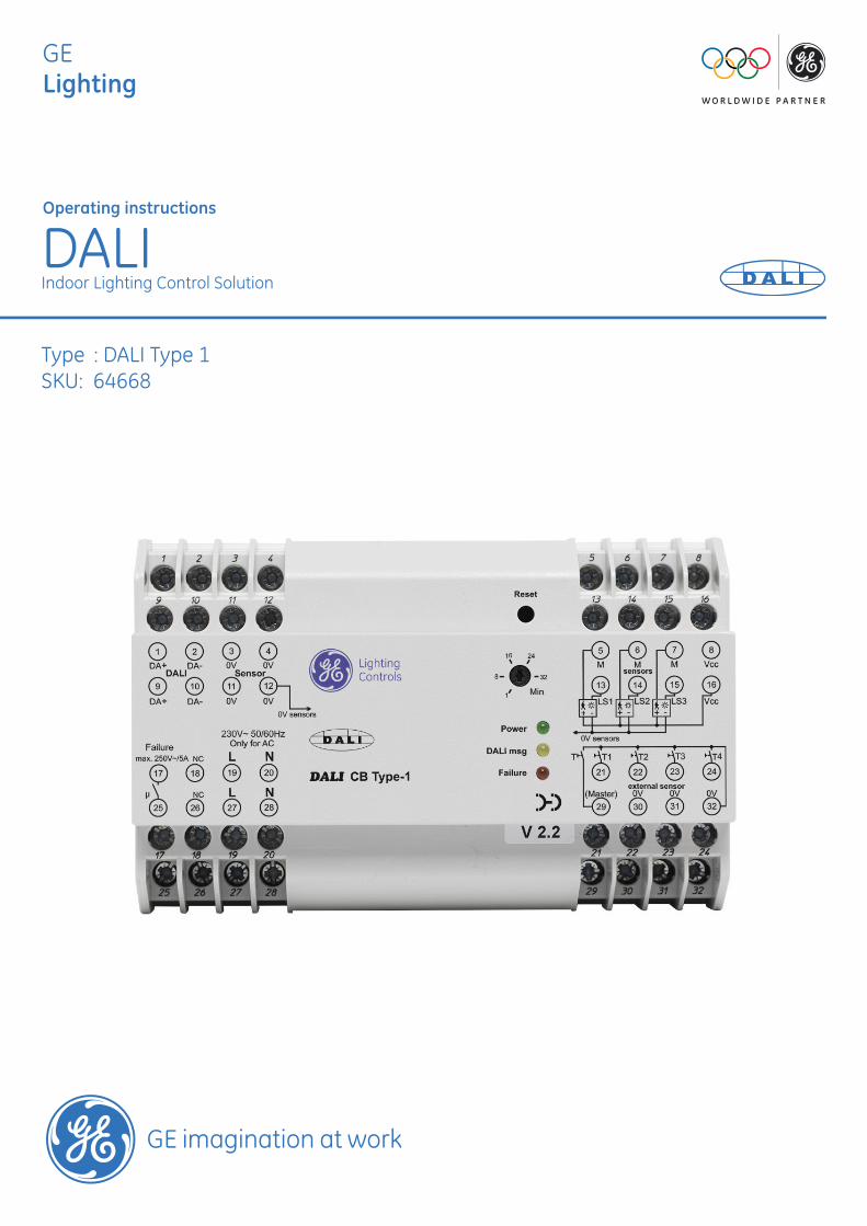
GE Lighting Operating instructions DALI Indoor Lighting Control Solution Type : DALI Type 1 SKU: 64668
GE Lighting
Operating instructions
DALIIndoor Lighting Control Solution
Type : DALI Type 1SKU: 64668
Contents Page
Applications and function 3
Setting up 4Construction site mode 4Button test 4Basic setting/reset 4Group assignment: Group test, Changing groups 4/5
System messages 5ON, DALI faults, DALI lamp faults 5
Operation 6Master sum function 6Individual group function 6Scenes: Storing scenes, Calling up scenes 6
Sensors 6Light sensors/ daylight depending lighting control (scene 1) 6Light/motion sensors, presence detection 7Notes on installing light/motion sensors 7
Safety and installation instructions 7Technical data 8/9DALI interface on the controller 9Mains failure/DALI failure 9Replacing/expanding units 9Control buttons 9
Wiring diagrams with brief descriptions 10-13DALI Controller without sensors: lighting control 10DALI Controller with a light sensor at LS1: Group 1 lighting control 11DALI Controller with two light and motion sensors connected in parallel at LS1 12DALI Controller with three light and motion sensors at LS1-LS3 13
Locking setting up and scene storage 14Accessories 14Space for user entries on the configuration, arrangement and set-up 15Overview of DALI Type 1 16
Applications and functions
The DALI CB Type 1 is a multifunctional control unit for cost-effective easy-to-use lighting control. It can be used for both closed-loop control (daylight/presence-dependent) and open-loop control.
The Type 1 Controller enables four luminaire groups to be freely configured and four different scenes (separate light settings for the entire room) to be set up and stored on the basis of individual brightness settings for these luminaires. The controller can operate up to 64 DALI units. These units may be ECGs or DALI to 1-10V converters.
They are set up and operated with up to five standard switches for mains voltage (there is no need for a separate program-
ming unit). The lighting system can be adapted at any time to suit different requirements.
Detailed description:
Of the four available scenes, scene 1 is reserved for constant lighting control; a maximum of three control circuits for con-stant lighting control (daylight-dependent dimming) can be created. The three other scenes are integrated in the presence function, but do not support constant lighting control. The light sensors are assigned permanently to groups 1 to 3 by means of the wiring.
When someone enters the room the presence function activates scene 1 (constant light scene). If a different setting is select-ed (for example scene 2 for a presentation) this setting will remain in force until the system reverts to its basic state a certain time after the last person has left the room.
The sensors start working as soon as power is supplied to the Type 1 Controller. If sensors (light/presence) are not linked to the controller, these functions will not be available. In this case, the controller will operate simply as an open-loop control unit and not as a closed-loop control unit. A maximum of six sensors can be connected. The presence function works across all the connected sensors.
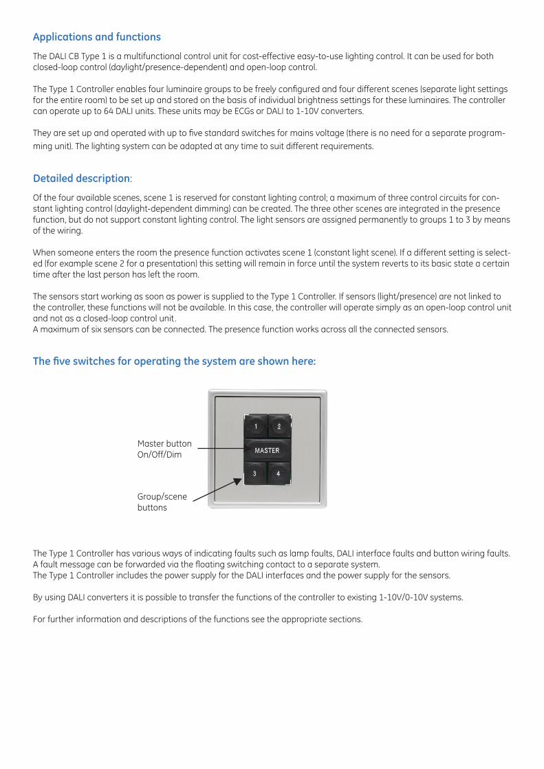
The five switches for operating the system are shown here:
The Type 1 Controller has various ways of indicating faults such as lamp faults, DALI interface faults and button wiring faults. A fault message can be forwarded via the floating switching contact to a separate system. The Type 1 Controller includes the power supply for the DALI interfaces and the power supply for the sensors.
By using DALI converters it is possible to transfer the functions of the controller to existing 1-10V/0-10V systems.
For further information and descriptions of the functions see the appropriate sections.
Master button On/Off/Dim
Group/scenebuttons
Setting upConstruction site mode:
The entire system can be operated at any time with the master button (master sum function) whether it has been configured or not. Briefly pressing the button switches all the DALI units on or off. Holding the button down will adjust the brightness of the lamps connected to all the DALI units (up or down). This enables the wiring of the central button and the function of all the DALI units to be tested.
Button test
In this test mode the wiring of switches T1 to T4 can be tested. To start the test, briefly press the reset button on the control-ler; the lamps of all the DALI units will come on at their minimum light settings.Pressing button T1 causes the lighting to flash once, pressing T2 causes it to flash twice, and so on. Press the master button to exit from this test mode.
Basic setting/reset
The reset button is used to place the system in a defined initial state when the system is first used and enables it to return quickly to its basic setting. All the units are assigned to the first group and scene 1 to 4 are predefined. If none of the units has ever been assigned to a group (“new system“) the DALI controller performs this basic setting automatically when power is supplied. Performing a reset:Interrupt the power supply to the controller and wait until the “ON” LED goes out. Hold down the Reset button and at the same time restore the power supply. Release the Reset button as soon as the “Fault” LED goes out.
Note:A reset will cancel all group assignments and scene settings.
Group assignment
Group assignments are locked by a code so they cannot be inadvertently changed. The procedure for removing this lock is as follows:
• Hold down the master button, T1 and T2 simultaneously for about 5 seconds until the entire system flashes. Now release the buttons.• In the next 10 seconds press the master button again and hold down for about 5 seconds until the entire system is switched to the minimum dimmer setting. Now release the master button.The controller will now search for DALI units. As soon as one is identified its lamp will start to flash. The unit can now be as-signed to one of the four groups 1 to 4 by pressing one of the switches T1 to T4.
The DALI units that already belong to the group will switch their lamps to maximum brightness while the lamp(s) of the unit to be assigned will continue to flash. The lamps of all other units will remain at their minimum brightness levels (assignment control). The assignment may be changed by pressing a different switch (T1 to T4) any number of times until the desired configuration has been found. The assignment to the group for the current unit is not stored until the master button is clicked. The control-ler then automatically searches for the next DALI unit. As soon as the last unit has been assigned the group assignment mode is automatically ended. This is indicated by the entire lighting system flashing once.
Note:The search for DALI units may take a few seconds. The order in which the units are found is random.
The group assignment can be locked (for details see page 14).
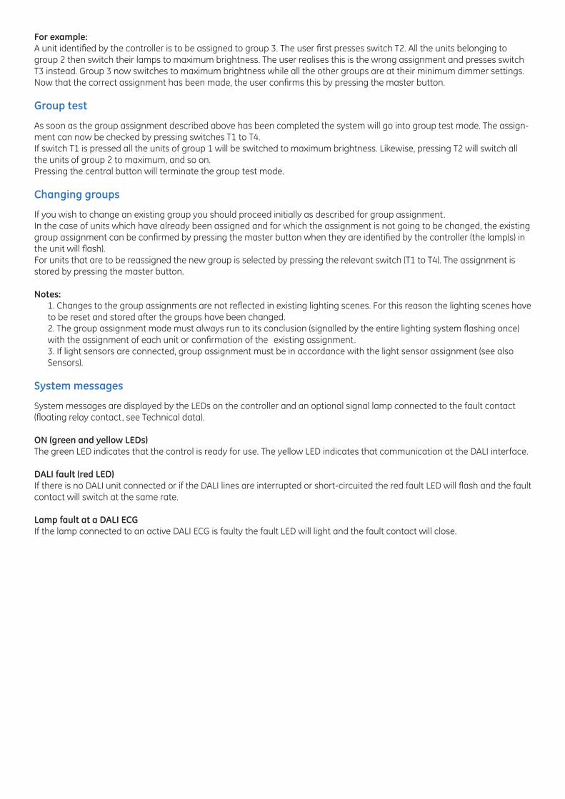
For example:A unit identified by the controller is to be assigned to group 3. The user first presses switch T2. All the units belonging to group 2 then switch their lamps to maximum brightness. The user realises this is the wrong assignment and presses switch T3 instead. Group 3 now switches to maximum brightness while all the other groups are at their minimum dimmer settings. Now that the correct assignment has been made, the user confirms this by pressing the master button.
Group test
As soon as the group assignment described above has been completed the system will go into group test mode. The assign-ment can now be checked by pressing switches T1 to T4.If switch T1 is pressed all the units of group 1 will be switched to maximum brightness. Likewise, pressing T2 will switch all the units of group 2 to maximum, and so on. Pressing the central button will terminate the group test mode.
Changing groups
If you wish to change an existing group you should proceed initially as described for group assignment. In the case of units which have already been assigned and for which the assignment is not going to be changed, the existing group assignment can be confirmed by pressing the master button when they are identified by the controller (the lamp(s) in the unit will flash). For units that are to be reassigned the new group is selected by pressing the relevant switch (T1 to T4). The assignment is stored by pressing the master button.
Notes:1. Changes to the group assignments are not reflected in existing lighting scenes. For this reason the lighting scenes have to be reset and stored after the groups have been changed. 2. The group assignment mode must always run to its conclusion (signalled by the entire lighting system flashing once) with the assignment of each unit or confirmation of the existing assignment.3. If light sensors are connected, group assignment must be in accordance with the light sensor assignment (see also Sensors).
System messages
System messages are displayed by the LEDs on the controller and an optional signal lamp connected to the fault contact (floating relay contact, see Technical data).
ON (green and yellow LEDs)The green LED indicates that the control is ready for use. The yellow LED indicates that communication at the DALI interface.
DALI fault (red LED)If there is no DALI unit connected or if the DALI lines are interrupted or short-circuited the red fault LED will flash and the fault contact will switch at the same rate.
Lamp fault at a DALI ECGIf the lamp connected to an active DALI ECG is faulty the fault LED will light and the fault contact will close.
Operation
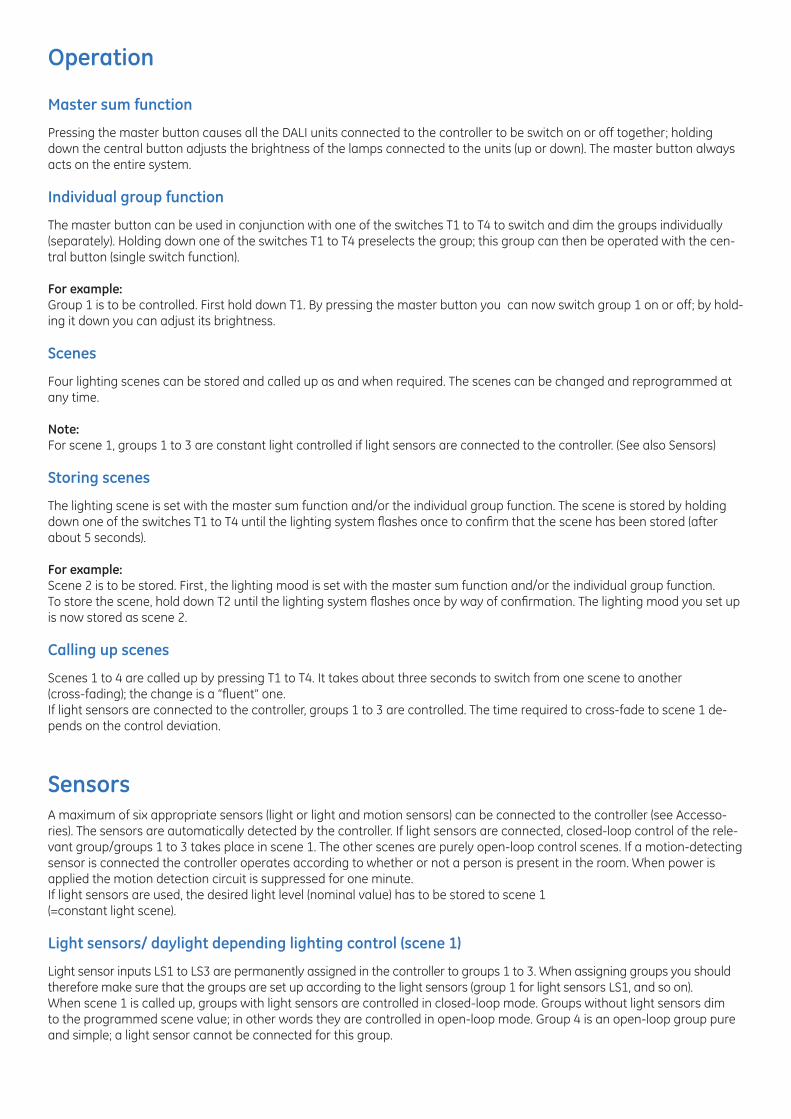
Master sum function
Pressing the master button causes all the DALI units connected to the controller to be switch on or off together; holding down the central button adjusts the brightness of the lamps connected to the units (up or down). The master button always acts on the entire system.
Individual group function
The master button can be used in conjunction with one of the switches T1 to T4 to switch and dim the groups individually (separately). Holding down one of the switches T1 to T4 preselects the group; this group can then be operated with the cen-tral button (single switch function).
For example:Group 1 is to be controlled. First hold down T1. By pressing the master button you can now switch group 1 on or off; by hold-ing it down you can adjust its brightness.
Scenes
Four lighting scenes can be stored and called up as and when required. The scenes can be changed and reprogrammed at any time.
Note:For scene 1, groups 1 to 3 are constant light controlled if light sensors are connected to the controller. (See also Sensors)
Storing scenes
The lighting scene is set with the master sum function and/or the individual group function. The scene is stored by holding down one of the switches T1 to T4 until the lighting system flashes once to confirm that the scene has been stored (after about 5 seconds).
For example:Scene 2 is to be stored. First, the lighting mood is set with the master sum function and/or the individual group function. To store the scene, hold down T2 until the lighting system flashes once by way of confirmation. The lighting mood you set up is now stored as scene 2.
Calling up scenes
Scenes 1 to 4 are called up by pressing T1 to T4. It takes about three seconds to switch from one scene to another (cross-fading); the change is a “fluent” one. If light sensors are connected to the controller, groups 1 to 3 are controlled. The time required to cross-fade to scene 1 de-pends on the control deviation.
SensorsA maximum of six appropriate sensors (light or light and motion sensors) can be connected to the controller (see Accesso-ries). The sensors are automatically detected by the controller. If light sensors are connected, closed-loop control of the rele-vant group/groups 1 to 3 takes place in scene 1. The other scenes are purely open-loop control scenes. If a motion-detecting sensor is connected the controller operates according to whether or not a person is present in the room. When power is applied the motion detection circuit is suppressed for one minute. If light sensors are used, the desired light level (nominal value) has to be stored to scene 1(=constant light scene).
Light sensors/ daylight depending lighting control (scene 1)
Light sensor inputs LS1 to LS3 are permanently assigned in the controller to groups 1 to 3. When assigning groups you should therefore make sure that the groups are set up according to the light sensors (group 1 for light sensors LS1, and so on). When scene 1 is called up, groups with light sensors are controlled in closed-loop mode. Groups without light sensors dim to the programmed scene value; in other words they are controlled in open-loop mode. Group 4 is an open-loop group pure and simple; a light sensor cannot be connected for this group.
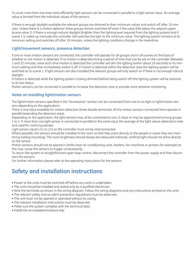
To cover more than one area more efficiently light sensors can be connected in parallel to a light sensor input. An average value is formed from the individual values of the sensors.
If there is enough daylight available the relevant groups are dimmed to their minimum values and switch off after 10 min-utes. Unless there is a motion detector these groups remain switched off even if the value falls below the setpoint again (scene value 1). If there is enough natural daylight (brighter than the lighting level required from the lighting system) and if scene 1 is called up manually the controller still switches the light to the minimum value. The lighting system remains at its minimum setting and switches off after 10 minutes, unless the lighting conditions change in the meantime.
Light/movement sensors, presence detection
If one or more motion sensors are connected, the controller will operate for all groups and in all scenes on the basis of whether or not motion is detected. If no motion is detected during a period of time that can be set on the controller (between 1 and 32 minutes, reset each time motion is detected) the controller will dim the lighting (within about 16 seconds) to its min-imum setting and then immediately switch it off. If motion is detected within the detection area the lighting system will be switched on to scene 1. If light sensors are also installed the relevant groups will only switch on if there is not enough natural daylight. If motion is detected while the lighting system is being dimmed (before being switch off) the lighting system will be restored to its last status. Motion sensors can be connected in parallel to increase the detection area or provide more sensitive monitoring.
Notes on installing light/motion sensors
The light/motion sensors specified in the “Accessories” section can be connected (from one to six light or light/motion sen-sors depending on the application). There is one input available for motion detection (three double terminals). All the motion sensors connected here operate in parallel (extending the detection area). Depending on the application, the light sensors may all be connected to one LS input or may be apportioned among groups 1 to 3. If more than one light sensor is connected in parallel to the same input the average of the light values detected is take and used for control purposes. Light sensor inputs LS1 to LS3 on the controller must not be interconnected. Where possible, the sensors should be installed in the room so that they point directly to the people or areas they are moni-toring (ceiling mounting). The room brightness should always be measured indirectly; artificial light should not shine directly on the sensor. Motion sensors should not be placed in drafts (near air-conditioning units, heaters, fax machines or printers for example) as this may cause the sensors to trigger unnecessarily. To return the system to straightforward open-loop control, disconnect the controller from the power supply and then discon-nect the sensors. For further information please refer to the operating instructions for the sensors.
Safety and installation instructions
• Power to the units must be switched off before any work is undertaken. • The units should be installed and tested only by a qualified electrician.• Wire the terminals as shown in the wiring diagram. Follow the wiring diagrams and any instructions printed on the units.• The relevant safety and accident prevention regulations must be observed.• The unit must not be opened or operated without its casing.• The relevant installation instructions must be observed.• Make sure the system complies with the technical data.• Install into an insulated enclosure only.
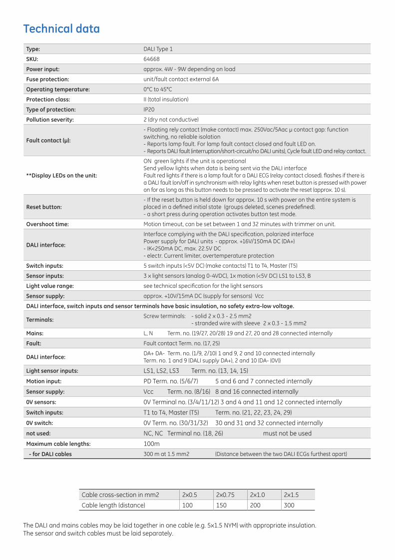
Type: DALI Type 1
SKU: 64668
Power input: approx. 4W - 9W depending on load
Fuse protection: unit/fault contact external 6A
Operating temperature: 0°C to 45°C
Protection class: II (total insulation)
Type of protection: IP20
Pollution severity: 2 (dry not conductive)
Fault contact (µ):
- Floating rely contact (make contact) max. 250Vac/5Aac µ contact gap: function switching, no reliable isolation- Reports lamp fault. For lamp fault contact closed and fault LED on.- Reports DALI fault (interruption/short-circuit/no DALI units), Cycle fault LED and relay contact.
**Display LEDs on the unit:
ON green lights if the unit is operationalSend yellow lights when data is being sent via the DALI interfaceFault red lights if there is a lamp fault for a DALI ECG (relay contact closed). flashes if there is a DALI fault (on/off in synchronism with relay lights when reset button is pressed with power on for as long as this button needs to be pressed to activate the reset (approx. 10 s).
Reset button:- If the reset button is held down for approx. 10 s with power on the entire system is placed in a defined initial state (groups deleted, scenes predefined).- a short press during operation activates button test mode.
Overshoot time: Motion timeout, can be set between 1 and 32 minutes with trimmer on unit.
DALI interface:
Interface complying with the DALI specification, polarized interfacePower supply for DALI units - approx. +16V/150mA DC (DA+) - IK<250mA DC, max. 22.5V DC- electr. Current limiter, overtemperature protection
Switch inputs: 5 switch inputs (<5V DC) (make contacts) T1 to T4, Master (T5)
Sensor inputs: 3 x light sensors (analog 0-4VDC), 1x motion (<5V DC) LS1 to LS3, B
Light value range: see technical specification for the light sensors
Sensor supply: approx. +10V/15mA DC (supply for sensors) Vcc
DALI interface, switch inputs and sensor terminals have basic insulation, no safety extra-low voltage.
Terminals: Screw terminals: - solid 2 x 0.3 - 2.5 mm2 - stranded wire with sleeve 2 x 0.3 - 1.5 mm2
Mains: L, N Term. no. (19/27, 20/28) 19 and 27, 20 and 28 connected internally
Fault: Fault contact Term. no. (17, 25)
DALI interface: DA+ DA- Term. no. (1/9, 2/10) 1 and 9, 2 and 10 connected internallyTerm. no. 1 and 9 (DALI supply DA+), 2 and 10 (DA- (0V))
Light sensor inputs: LS1, LS2, LS3 Term. no. (13, 14, 15)
Motion input: PD Term. no. (5/6/7) 5 and 6 and 7 connected internally
Sensor supply: Vcc Term. no. (8/16) 8 and 16 connected internally
0V sensors: 0V Terminal no. (3/4/11/12) 3 and 4 and 11 and 12 connected internally
Switch inputs: T1 to T4, Master (T5) Term. no. (21, 22, 23, 24, 29)
0V switch: 0V Term. no. (30/31/32) 30 and 31 and 32 connected internally
not used: NC, NC Terminal no. (18, 26) must not be used
Maximum cable lengths: 100m
- for DALI cables 300 m at 1.5 mm2 (Distance between the two DALI ECGs furthest apart)
Cable cross-section in mm2 2x0.5 2x0.75 2x1.0 2x1.5
Cable length (distance) 100 150 200 300
The DALI and mains cables may be laid together in one cable (e.g. 5x1.5 NYM) with appropriate insulation.The sensor and switch cables must be laid separately.
Technical data
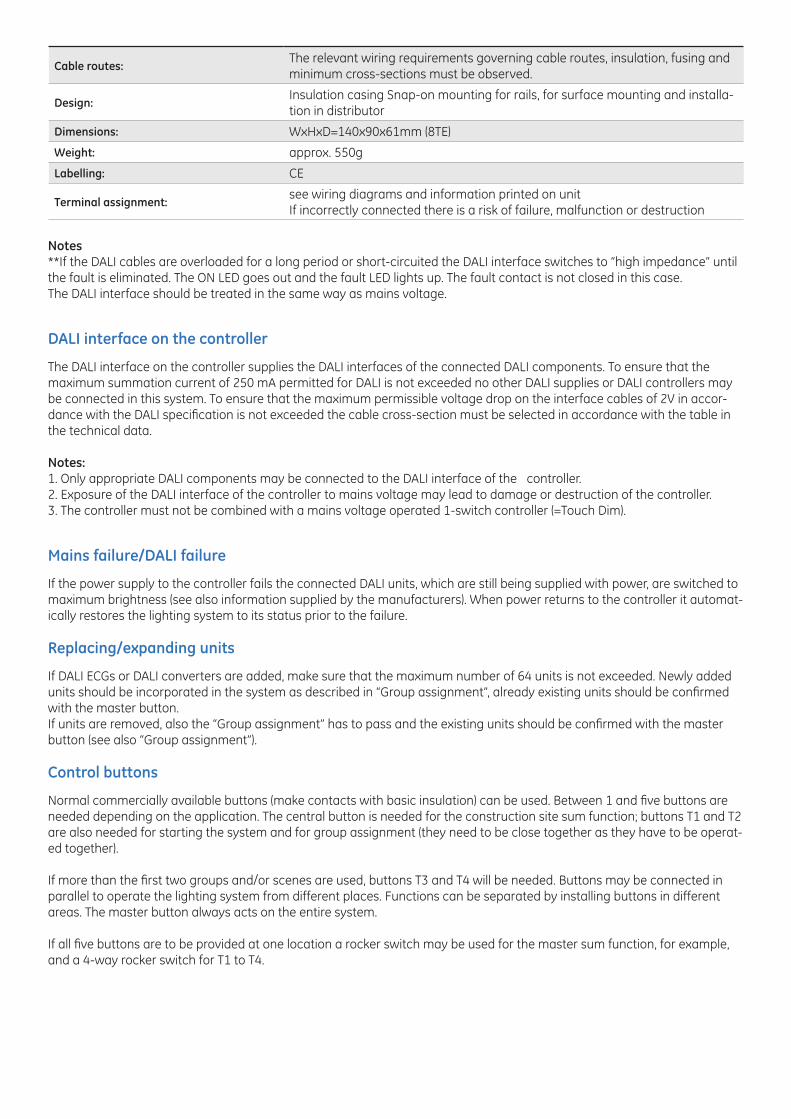
Notes **If the DALI cables are overloaded for a long period or short-circuited the DALI interface switches to “high impedance” until the fault is eliminated. The ON LED goes out and the fault LED lights up. The fault contact is not closed in this case. The DALI interface should be treated in the same way as mains voltage.
DALI interface on the controller
The DALI interface on the controller supplies the DALI interfaces of the connected DALI components. To ensure that the maximum summation current of 250 mA permitted for DALI is not exceeded no other DALI supplies or DALI controllers may be connected in this system. To ensure that the maximum permissible voltage drop on the interface cables of 2V in accor-dance with the DALI specification is not exceeded the cable cross-section must be selected in accordance with the table in the technical data.
Notes:1. Only appropriate DALI components may be connected to the DALI interface of the controller. 2. Exposure of the DALI interface of the controller to mains voltage may lead to damage or destruction of the controller. 3. The controller must not be combined with a mains voltage operated 1-switch controller (=Touch Dim).
Mains failure/DALI failure
If the power supply to the controller fails the connected DALI units, which are still being supplied with power, are switched to maximum brightness (see also information supplied by the manufacturers). When power returns to the controller it automat-ically restores the lighting system to its status prior to the failure.
Replacing/expanding units
If DALI ECGs or DALI converters are added, make sure that the maximum number of 64 units is not exceeded. Newly added units should be incorporated in the system as described in “Group assignment”, already existing units should be confirmed with the master button. If units are removed, also the “Group assignment” has to pass and the existing units should be confirmed with the master button (see also “Group assignment”).
Control buttons
Normal commercially available buttons (make contacts with basic insulation) can be used. Between 1 and five buttons are needed depending on the application. The central button is needed for the construction site sum function; buttons T1 and T2 are also needed for starting the system and for group assignment (they need to be close together as they have to be operat-ed together).
If more than the first two groups and/or scenes are used, buttons T3 and T4 will be needed. Buttons may be connected in parallel to operate the lighting system from different places. Functions can be separated by installing buttons in different areas. The master button always acts on the entire system.
If all five buttons are to be provided at one location a rocker switch may be used for the master sum function, for example, and a 4-way rocker switch for T1 to T4.
Cable routes:The relevant wiring requirements governing cable routes, insulation, fusing and minimum cross-sections must be observed.
Design:Insulation casing Snap-on mounting for rails, for surface mounting and installa-tion in distributor
Dimensions: WxHxD=140x90x61mm (8TE)
Weight: approx. 550g
Labelling: CE
Terminal assignment:see wiring diagrams and information printed on unitIf incorrectly connected there is a risk of failure, malfunction or destruction
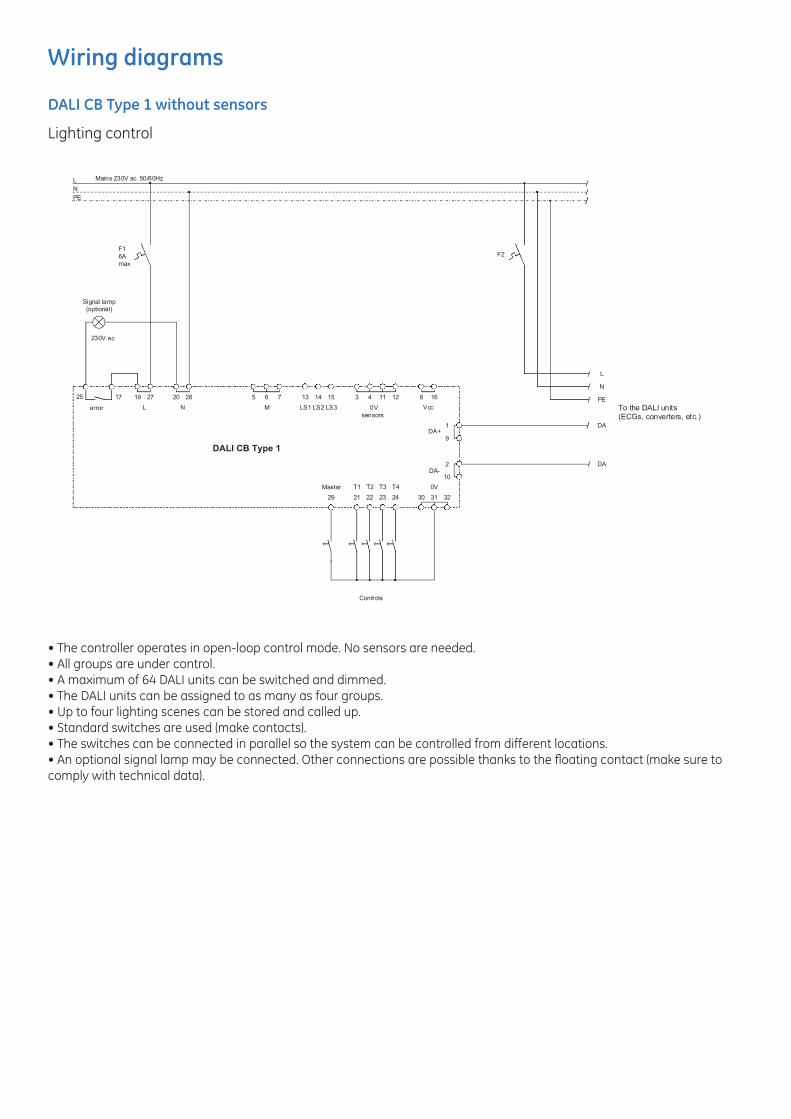
Wiring diagrams
DALI CB Type 1 without sensors
Lighting control
• The controller operates in open-loop control mode. No sensors are needed.• All groups are under control.• A maximum of 64 DALI units can be switched and dimmed.• The DALI units can be assigned to as many as four groups.• Up to four lighting scenes can be stored and called up.• Standard switches are used (make contacts).• The switches can be connected in parallel so the system can be controlled from different locations.• An optional signal lamp may be connected. Other connections are possible thanks to the floating contact (make sure to comply with technical data).
L
PEN
Mains 230V ac 50/60Hz
Signal lamp (optional)
230V ac
error L N
19 271725 20 28 65 7
M
13 15
LS3LS2LS1
121143
0Vsensors
168
Vcc
DA+9
2
10
1
DA-
242322
T4
3231302129
0VT1Master
Controls
14
T2 T3
F16Amax
DALI CB Type 1
To the DALI units(ECGs, converters, etc.)
L
N
PE
DA
DA
F2
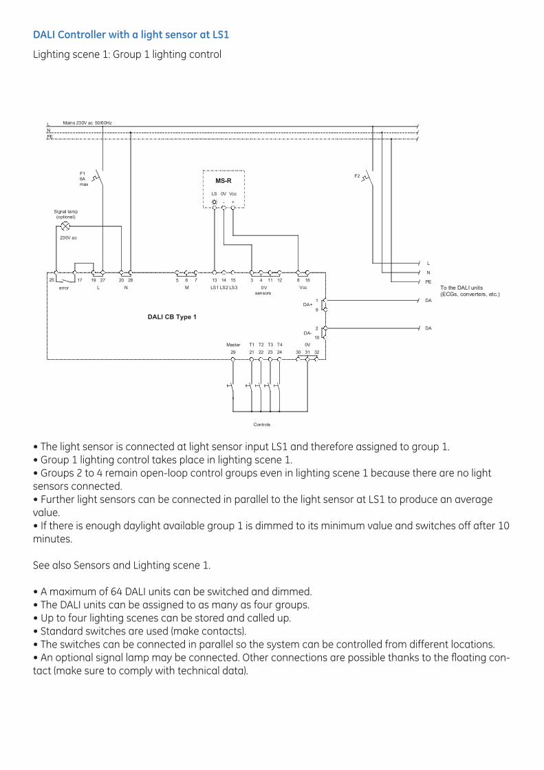
DALI Controller with a light sensor at LS1
Lighting scene 1: Group 1 lighting control
• The light sensor is connected at light sensor input LS1 and therefore assigned to group 1.• Group 1 lighting control takes place in lighting scene 1.• Groups 2 to 4 remain open-loop control groups even in lighting scene 1 because there are no light sensors connected.• Further light sensors can be connected in parallel to the light sensor at LS1 to produce an average value. • If there is enough daylight available group 1 is dimmed to its minimum value and switches off after 10 minutes.
See also Sensors and Lighting scene 1.
• A maximum of 64 DALI units can be switched and dimmed.• The DALI units can be assigned to as many as four groups.• Up to four lighting scenes can be stored and called up.• Standard switches are used (make contacts).• The switches can be connected in parallel so the system can be controlled from different locations.• An optional signal lamp may be connected. Other connections are possible thanks to the floating con-tact (make sure to comply with technical data).
L
PEN
Mains 230V ac 50/60Hz
Signal lamp (optional)
230V ac
error L N
19 271725 20 28 65 7
M
13 15
LS3LS2LS1
121143
0Vsensors
168
Vcc
DA+9
2
10
1
DA-
242322
T4
3231302129
0VT1Master
Controls
14
T2 T3
F16Amax
DALI CB Type 1
To the DALI units(ECGs, converters, etc.)
L
N
PE
DA
DA
- +
LS 0V Vcc
MS-RF2
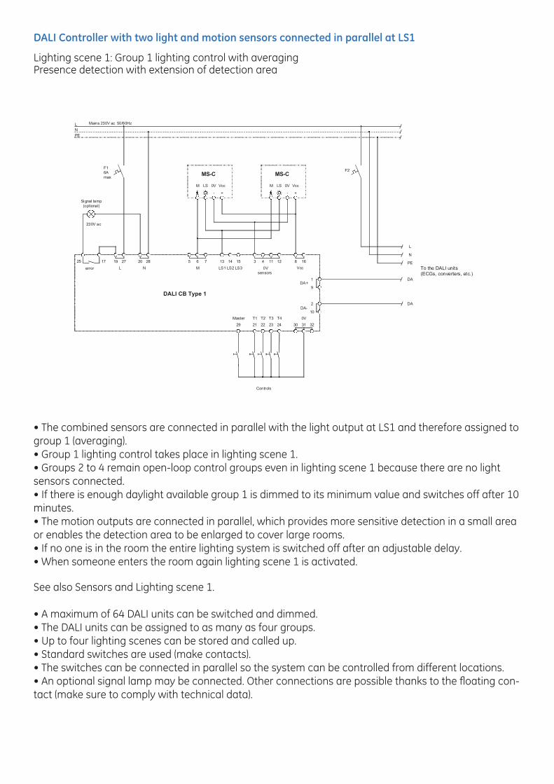
DALI Controller with two light and motion sensors connected in parallel at LS1
Lighting scene 1: Group 1 lighting control with averagingPresence detection with extension of detection area
• The combined sensors are connected in parallel with the light output at LS1 and therefore assigned to group 1 (averaging).• Group 1 lighting control takes place in lighting scene 1.• Groups 2 to 4 remain open-loop control groups even in lighting scene 1 because there are no light sensors connected.• If there is enough daylight available group 1 is dimmed to its minimum value and switches off after 10 minutes.• The motion outputs are connected in parallel, which provides more sensitive detection in a small area or enables the detection area to be enlarged to cover large rooms.• If no one is in the room the entire lighting system is switched off after an adjustable delay.• When someone enters the room again lighting scene 1 is activated.
See also Sensors and Lighting scene 1.
• A maximum of 64 DALI units can be switched and dimmed.• The DALI units can be assigned to as many as four groups.• Up to four lighting scenes can be stored and called up.• Standard switches are used (make contacts).• The switches can be connected in parallel so the system can be controlled from different locations.• An optional signal lamp may be connected. Other connections are possible thanks to the floating con-tact (make sure to comply with technical data).
L
PEN
Mains 230V ac 50/60Hz
Signal lamp (optional)
230V ac
error L N
19 271725 20 28 65 7
M
13 15
LS3LS2LS1
121143
0Vsensors
168
Vcc
DA+9
2
10
1
DA-
242322
T4
3231302129
0VT1Master
Controls
14
T2 T3
F16Amax
DALI CB Type 1
To the DALI units(ECGs, converters, etc.)
L
N
PE
DA
DA
- +
M LS 0V Vcc
MS-C
- +
M LS 0V Vcc
MS-CF2
DALI Controller with three light and motion sensors at LS1 to LS3
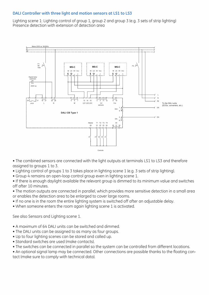
Lighting scene 1: Lighting control of group 1, group 2 and group 3 (e.g. 3 sets of strip lighting)Presence detection with extension of detection area
• The combined sensors are connected with the light outputs at terminals LS1 to LS3 and therefore assigned to groups 1 to 3.• Lighting control of groups 1 to 3 takes place in lighting scene 1 (e.g. 3 sets of strip lighting).• Group 4 remains an open-loop control group even in lighting scene 1.• If there is enough daylight available the relevant group is dimmed to its minimum value and switches off after 10 minutes.• The motion outputs are connected in parallel, which provides more sensitive detection in a small area or enables the detection area to be enlarged to cover large rooms.• If no one is in the room the entire lighting system is switched off after an adjustable delay.• When someone enters the room again lighting scene 1 is activated.
See also Sensors and Lighting scene 1.
• A maximum of 64 DALI units can be switched and dimmed.• The DALI units can be assigned to as many as four groups.• Up to four lighting scenes can be stored and called up.• Standard switches are used (make contacts).• The switches can be connected in parallel so the system can be controlled from different locations.• An optional signal lamp may be connected. Other connections are possible thanks to the floating con-tact (make sure to comply with technical data).
F2
L
PEN
Mains 230V ac 50/60Hz
Signal lamp (optional)
230V ac
error L N
19 271725 20 28 65 7
M
13 15
LS3LS2LS1
121143
0Vsensors
168
Vcc
DA+9
2
10
1
DA-
242322
T4
3231302129
0VT1Master
Controls
14
T2 T3
F16Amax
To the DALI units(ECGs, converters, etc.)
L
N
PE
DA
DA
- +
LS 0V Vcc
- +
LS 0V Vcc
- +
LS 0V Vcc M
DALI CB Type 1
MS-C MS-CM
MS-CM
Accessories
Electrical control components
Electronic control gear with DALI interface
1-10V DALI Converter 64932etc.
User control components
Standard switches (make contacts with basic insulation) Operating panels (make contacts with basic insulation)
Sensors
Light sensor (active) MS-R 64669Light and motion sensor (active) MS-C 64670
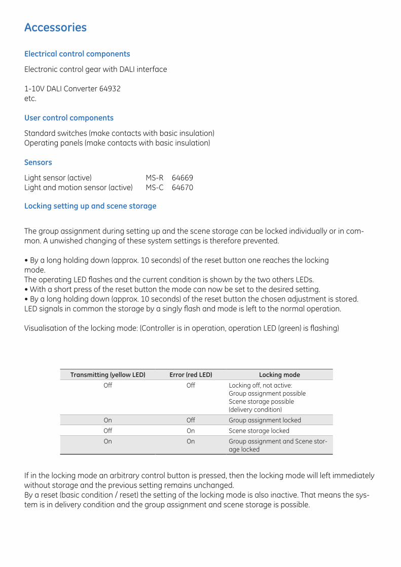
Locking setting up and scene storage
The group assignment during setting up and the scene storage can be locked individually or in com-mon. A unwished changing of these system settings is therefore prevented.
• By a long holding down (approx. 10 seconds) of the reset button one reaches the lockingmode.The operating LED flashes and the current condition is shown by the two others LEDs.• With a short press of the reset button the mode can now be set to the desired setting.• By a long holding down (approx. 10 seconds) of the reset button the chosen adjustment is stored.LED signals in common the storage by a singly flash and mode is left to the normal operation.
Visualisation of the locking mode: (Controller is in operation, operation LED (green) is flashing)
If in the locking mode an arbitrary control button is pressed, then the locking mode will left immediately without storage and the previous setting remains unchanged.By a reset (basic condition / reset) the setting of the locking mode is also inactive. That means the sys-tem is in delivery condition and the group assignment and scene storage is possible.
Transmitting (yellow LED) Error (red LED) Locking mode
Off Off Locking off, not active:Group assignment possibleScene storage possible (delivery condition)
On Off Group assignment locked
Off On Scene storage locked
On On Group assignment and Scene stor-age locked
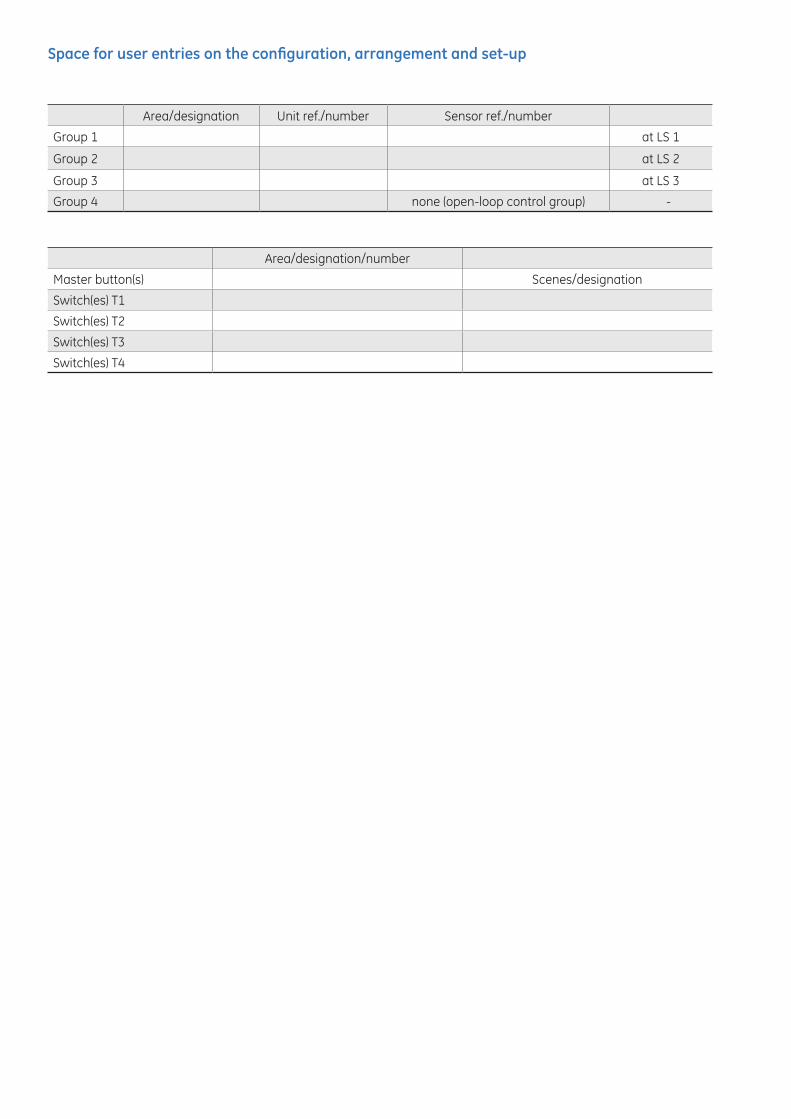
Space for user entries on the configuration, arrangement and set-up
Area/designation Unit ref./number Sensor ref./number
Group 1 at LS 1
Group 2 at LS 2
Group 3 at LS 3
Group 4 none (open-loop control group) -
Area/designation/number
Master button(s) Scenes/designation
Switch(es) T1
Switch(es) T2
Switch(es) T3
Switch(es) T4
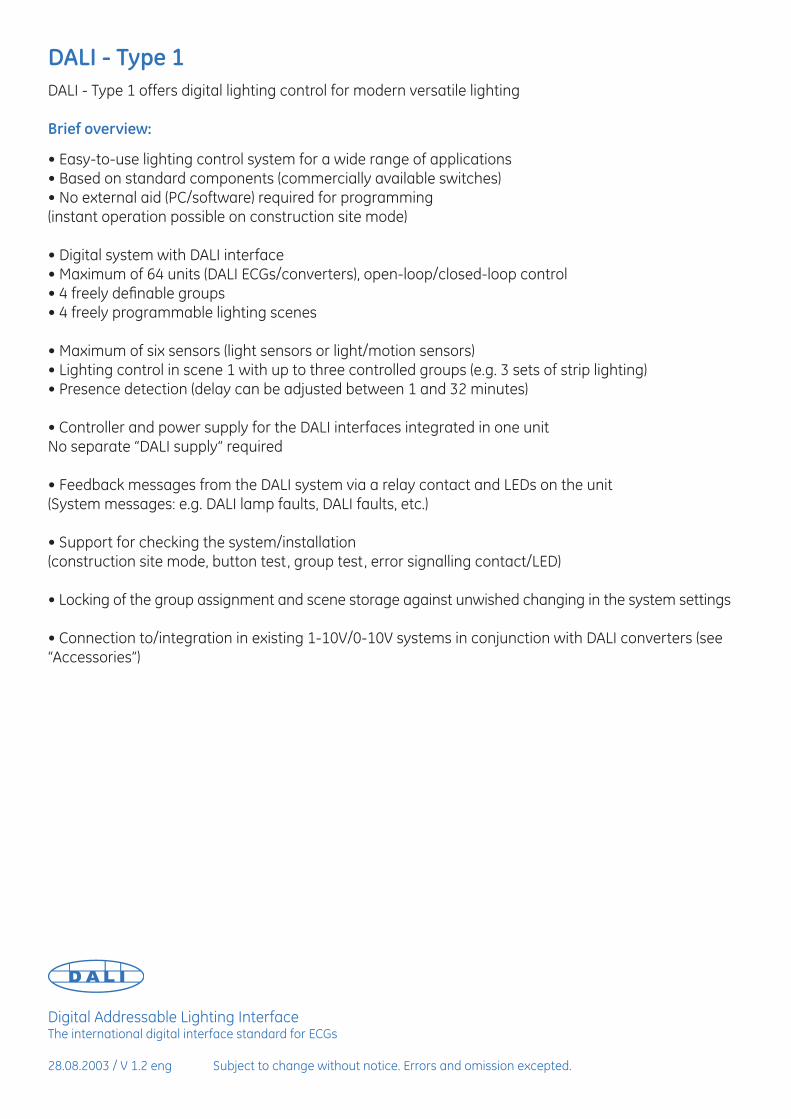
DALI - Type 1
DALI - Type 1 offers digital lighting control for modern versatile lighting
Brief overview:
• Easy-to-use lighting control system for a wide range of applications • Based on standard components (commercially available switches)• No external aid (PC/software) required for programming(instant operation possible on construction site mode)
• Digital system with DALI interface• Maximum of 64 units (DALI ECGs/converters), open-loop/closed-loop control• 4 freely definable groups• 4 freely programmable lighting scenes
• Maximum of six sensors (light sensors or light/motion sensors)• Lighting control in scene 1 with up to three controlled groups (e.g. 3 sets of strip lighting)• Presence detection (delay can be adjusted between 1 and 32 minutes)
• Controller and power supply for the DALI interfaces integrated in one unit No separate “DALI supply“ required
• Feedback messages from the DALI system via a relay contact and LEDs on the unit(System messages: e.g. DALI lamp faults, DALI faults, etc.)
• Support for checking the system/installation(construction site mode, button test, group test, error signalling contact/LED)
• Locking of the group assignment and scene storage against unwished changing in the system settings
• Connection to/integration in existing 1-10V/0-10V systems in conjunction with DALI converters (see “Accessories”)
Digital Addressable Lighting InterfaceThe international digital interface standard for ECGs
28.08.2003 / V 1.2 eng Subject to change without notice. Errors and omission excepted.
Information provided is subject to change without notice. Please verify all details with GE. All values are design or typical values when measured under laboratory conditions, and GE makes no warranty or guarantee, express or implied, that such performance will be obtained under end-use conditions.
ID nr: GE2022-7746_version1
NA:
GE LightingGeneral Electric companyNela ParkCleveland, OH 44112
EMEA:
GE Hungary Kft.Váci út 77.H-1044 BudapestHungary
www.gelighting.comand General Electric are both registered trademarks of the General Electric Company
Installation Instructions 03/2013
GELighting
Installation Guide
The English version of the installation instruction and safety information can be found at the following location:
Die deutsche Version der Installationsanleitung und Sicherheitsinformationen finden Sie in folgendem Verzeichnis:
La version française des instructions d’installation et informations de sécurité est disponible à l’adresse suivante :
La versione italiana del manuale di installazione e sicurezza può essere reperita nella seguente sezione:
La versión española de las instrucciones de instalación y la información sobre seguridad puede encontrarse en la siguiente ubicación:
A versão em Português das instruções de instalação e das informações de segurança pode ser encontrada na seguinte localização:
Versiunea în limba română a instrucţiunilor de instalare şi a informaţiilor de siguranţă pot fi găsite la:
Polską wersję instrukcji instalacji oraz informacje dotyczące bezpieczeństwa można znaleźć w następującej lokalizacji:
Návod k montáži a bezpečnostní informace v češtině najdete zde:
Slovenskú verziu montážnej príručky a bezpečnostných inštrukcií nájdete na nasledujúcej lokalite:
Hrvatska verzija priručnika za ugradnju i sigurnosnih informacija nalazi se na sljedećoj lokaciji:
Verziju uputstva za instalaciju i informacija o bezbednosti na srpskom jeziku možete pronaći na sledećoj lokaciji:
Slovenska različica navodil za namestitev in varnostnih navodil se nahaja na naslednji strani:
A telepítési útmutató és a biztonsági információk magyar nyelvű változata az alábbi címen található:
De Nederlandse versie van de installatie-instructies en veiligheidsinformatie kan op de volgende locatie worden gevonden:
Den danske version af installationsvejledningen og sikkerhedsoplysninger kan findes på følgende placering:
Asennusohjeiden ja turvallisuustietojen suomenkielinen versio löytyy seuraavasta paikasta:
Den norske versjonen av installasjonsinstruksjonene og sikkerhetsinformasjonen finnes under:
Ni hittar den svenska versionen av installationsanvisningarna och säkerhetsinformationen på följande plats:
Eestikeelse paigaldusjuhendi ja ohutusnõuded leiate aadressilt:
Uzstādīšanas instrukciju un drošības informāciju latviešu valodā var atrast šeit:
Lietuvišką diegimo instrukcijos ir saugos informacijos versiją galima rasti šioje vietoje:
Íslenska útgáfu af uppsetningarleiðbeiningum og öryggisupplýsingar er hægt að finna á eftirfarandi staðsetningu:
Μπορείτε να βρείτε την ελληνική εκδοχή των οδηγιών εγκατάστασης και των πληροφοριών ασφάλειας στην εξής τοποθεσία:
Русскую версию инструкции по установке и технике безопасности можно найти здесь:
Українська версія інструкції зі встановлення та інформація щодо безпеки знаходяться за такою адресою:
Българската версия на инструкциите за инсталация и информация за безопасност могат да бъдат намерени на следния адрес:
يمكن إيجاد النسخة العربية من إرشادات التثبيت ومعلومات األمان على الموقع التالي:
نسخه فارسی دستور العمل نصب و اطالعات ایمنی قابل دسترس است در:
Montaj talimatı ve güvenlik bilgilerinin Türkçe sürümü, aşağıdaki konumda bulunabilir:
ניתן למצוא הגרסה העברית של פרטי ההתקנה ופרטי הבטיחות בכתובת דלהלן:
可在以下位置获得安装说明及安全信息的国语版本:
日本語版のインソール説明及び安全情報は下記の場所から見つけられます
www.gelighting.com/installations
GB
D
F
I
E
P
RO
PL
CZ
SK
HR
SRB
SLO
H
NL
DK
FIN
N
S
EST
LV
LT
IS
GR
RUS
UA
BG
SA
IR
TR
IL
RC
J


