r .... . .. - - ... ... . .. I.. mu, Hgo, 2lMt Damage Analysis of Wire Rope From ,-4 a 34-Month Ocean Mooring N.J. ReNDLt' Ocean Technology Division October 1970 .pr Ropwducd by - - NATIONAL TECHNICAL Springfi.l, Va. 22151 cOLR u~srR~fMtS M'ODUCf. IN 3WAC AMD WWM NAVAL. mmRAIM ua~ra Wwpo f nta ft d 1 1. P. IqbS ~W 1
Correlation of Clues 16History of Events 17Extension of Service Life 19Prediction of Failure/Reliability 20
CONCLUSIONS AND RECOMMENDATIONS 20
ACKNOWLEDGMENTS 22
REFERENCES 23
ABSTRACT
Damage analysis of samples from a 304 stainless steel rope was conductedto determine the extent and origin of damage mechanism defects and to measure
their accumulated effect upon mooring line break strength. The rope waslocated in the upper portion of the NOMAD buoy mooring line and had beensubjected to 34 months of continuous immersion in the Gulf of Mexico. The
primary objective of this initial study was to supply corrective informationleading towards an extension of service life,
Damage defects of mechanical and electrochemical origin were identifiedand located in the 1250-foot length of wire rope mouring. A study of thesedefects revealed a specific pattern of degradation. Dominant centers ofdamage were associated with a wire rope deformation-bend and with a "protec-
tive" neoprene jacket cover. In each case the initiating damage mechanismwas identified as an abnormal mechanical motion which removed the protectivecoatings afforded by lubricant and cathodic protection. Subsequent corro-
sion of the stainless steel generated an abrasive sediment in the lubricantto promote a self-supporting degradation process. The wire rope retained88% of its initial break strength. Elimination of the causes that initiatedabnormal mechanical motion would increase this retained strength to 96%.
This study indicates the need to properly use post-service damageanalysis in optimization of buoy system design. A complete understandingof usage effects in terms of failure/reliability will depend upon continueddamage analysis during several prototype installations.
PROBLEM STATUS
This is a final report on this phase of the problem; work iscontinuing in other phases.
AUTHORIZATION
NRL Problem F02-23Project RRO09-03-45-5806
Manuscript submitted October 1970
i ii
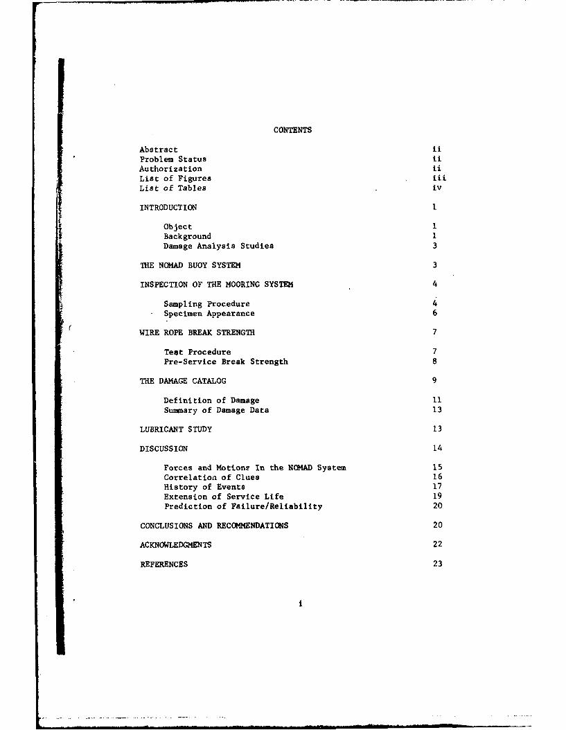
LIST OF FIGURES
1. The General NOMAD System
2. Appearance of Wire Rope Mooring Samples
3. Permanent Bend In 3/4" Stainless Steel Rope
4. Wire and Strand Labels and Identification of Major Rope Defects
5. Photograph of Relatively Undamaged Portion of the Rope
6. Mechanical Damage Defects
7. Wire Breaks and Corrosive Tunneling
8. Corrosion Defects
9. Forces and Motions In the General NOMAD System
ii
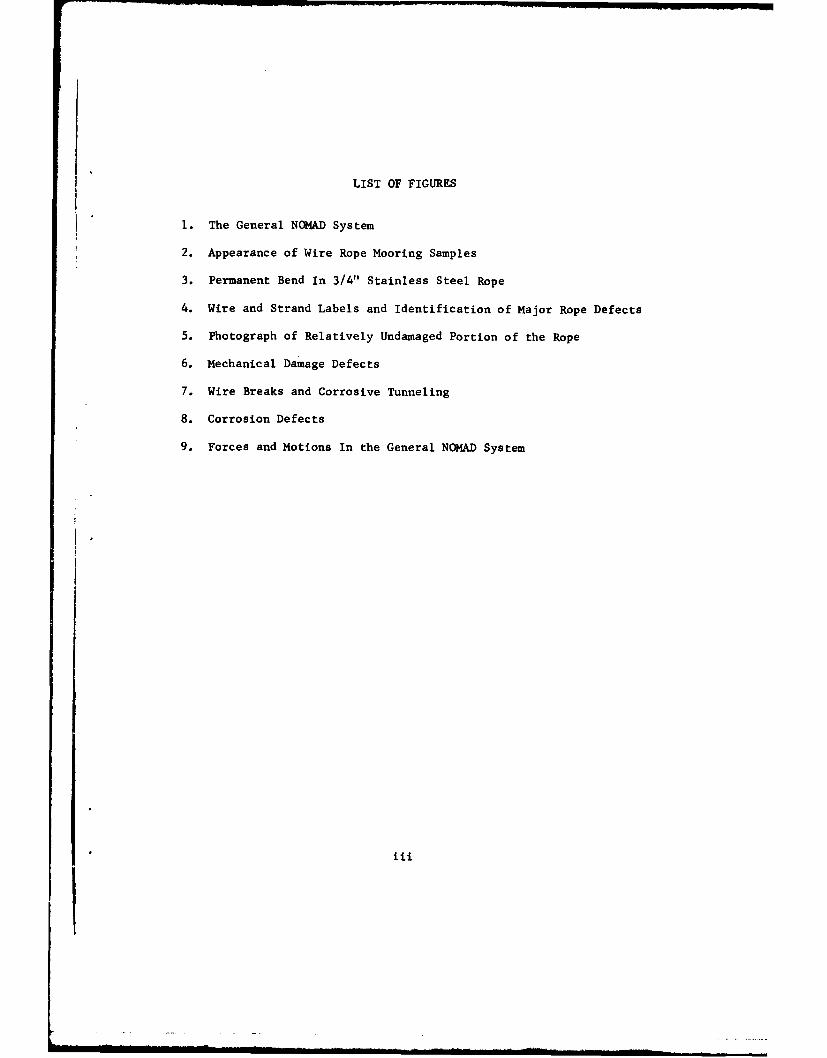
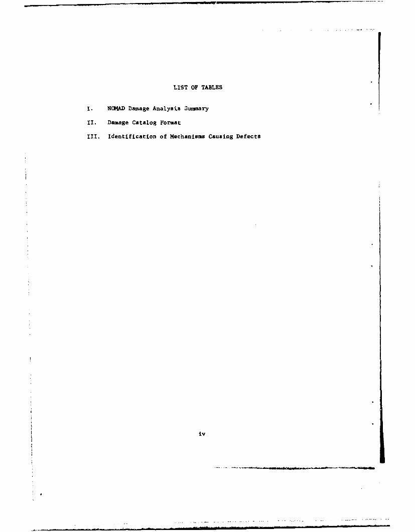
LIST OF TABLES
I. NGMAD Damage Analysis Summary
I. Damage Catalog Format
II. Identification of Mechanisms Causing Defects
iv
DAMAGE ANALYSIS OF WIRE ROPE FROMA 34-MONTH OCEAN MOORING
INTRODUCTION
Object
The opportunity to conduct a damage analysis study upon a portionof a NOMAD mooring line--from a mooring recovered after 34 months inthe ocean--presented itself during a period when moored buoy technol-ogy was being subjected to review. A significant part of this reviewof the design and engineering methods currently in use is the need forunderstanding failure mechanisms of wire rope often used in ocean moor-ings. The primary purpose here is to describe the procedures and re-sults of an initial study of the mechanical damage to wire rope after34 months in the Gulf of Mexico. As this study proceeded the scope wasbroadened somewhat to direct attention to greater possibilities forobtaining damage information when an overall program could be conducted.A concurrent study reported on corrosion effects to this wire rope (1).
Background
Before proceeding into a discussion of the damage studies it wouldbe well to review briefly the conditions that exist today in mooredbuoy technology, in an effort to place damage analysis in its propercontext.
Although moored buoy systems have been used for many years, therecent emphasis on ocean utilization has greatly increased interestin these marine structures. Such interest results from an expandedneed for oceanographic and meteorological data, as well as from thedesire to explore and work in the ocean and to monitor its physicalproperties. Not only is the number of potential buoy systems increasedbut the requirements for performance of such systems--including reli-able life, predictable motions, dependable installation and retrieval,and acceptable costs--have become more stringent. Illustrative ofthese requirements are the specifications for the National Data BuoySystem (2) and those of the Sea Spider installation (3). Once thesespecifications are reviewed and compared with previous requirementsthe full import of the new requirements is realized. Goals that in-clude low initial cost, improved longevity in service and predictabil-ity of system response to the environment can be achieved only if com-prehensive dynamic analyeic techniques exist and are fully supportedby good definition in all of the environmental and engineering param-eters, including damage/failure mechanisms. Current knowledge isinsufficient to meet this task; hence, research is required.
A current review of buoy technology has revealed the magnitude ofthe required research effort in pertinent areas. These areas include(a) analysis, to permit more accurate prediction of forces and motions
in moored buoy systems, (b) environment, to better specify the forcingfunctions and ocean conditions, (c) engineering parameters, to moreadequately prescribe hardware characteristics and properties, (d) opera-tional procedures, to establish dependable at-sea techniques for in-stallation and retrieval, and (e) damage analysis, to better understandthe effects of usage in terms of failure/reliability. Informationgathered by specialists in each of these areas (4-9) indicates thatprogress towards achievement of the optimum moored buoy design will bebest served through a concurrent approach in the programming of re-search. While some of the areas will lend themselves to quasi-indepen-dent programs of laboratory research (development of dynamic analytictechniques, quantitative measure of hardware characteristics) otherswill denend upon an influx of data gathered from initial prototypesystems (measurement of environment parameters, development of damageanalysis). A continuous program of prototype construction is importantto insure proper validation of new developments as these occur in allpertinent areas of buoy technology.
An additional aspect of buoy system research was made evident aswork progressed towards evaluation of damage in the NOMAD wire ropemooring. The in-sea mechanisms which produce damage and limit thelife of the buoy system are of mechanical, electro-chemical and bio-logical origin. Although separate study of these mechanisms throughlaboratory simulation and field experimentation has value, such studyby itself can reveal neither the extent nor the rate of degradationthat is produced when these mechanisms interact within the complexmarine environment. As is shown in a later section of this report,the techniques employed during post-service damage analysis may beused for an evaluation of these cumulative effects. Also, the fullworth of damage analysis cannot be realized unless it is supported bymeasurement of certain mechanical parameters of the system during theservice period, i.e., some limited means for conduction of in situresearch measurements should be included in specifications for theinitial prototype systems.
To summarize briefly, the most expeditious program for optimiza-tion of buoy system design will utilize data from a growing volume ofhydrospace research to improve the response of successive prototypesystems. Specifications for these systems should include the meansfor (1) fulfillment of their utilitarian purpose, (2) validation ofnew research developments and (3) conduct of in situ research. Post-service damage analysis can assist materially in the necessary designand development process. If the scope of these damage studies issufficiently broad they will supply feedback information essential togrowth in the overall program.
2
Damage Analysis Studies
Mechanical, electrochemical and biological mechanisms combine toproduce the accumulated damage found in a marine system. Duringdamage analysis the characteristic defects for each mechanism arefirst identified, then located and measured to reveal specific patternsof system degradation. The manner in which dominant centers of damagerelate to one another and interact within the system to produce over-stressed components is of interest. Once sufficient clues have beengathered as to the history of events that produced change in the sys-tem, it may be possible to isolate the initiating mechanism and suggestnew procedures for extension of system life. A detailed knowledge ofsystem design parameters is essential throughout this process and willprevent a purely subjective conclusion.
The scope and objective of damage analysis became clear only asthis initial study progressed and was paralleled with the effort tounderstand all of the problem areas in buoy technology. It is naturalthen that certain limitations in the current effort will appear: thesewill be noted in the text.
THE NOMAD BUOY SYSTEM
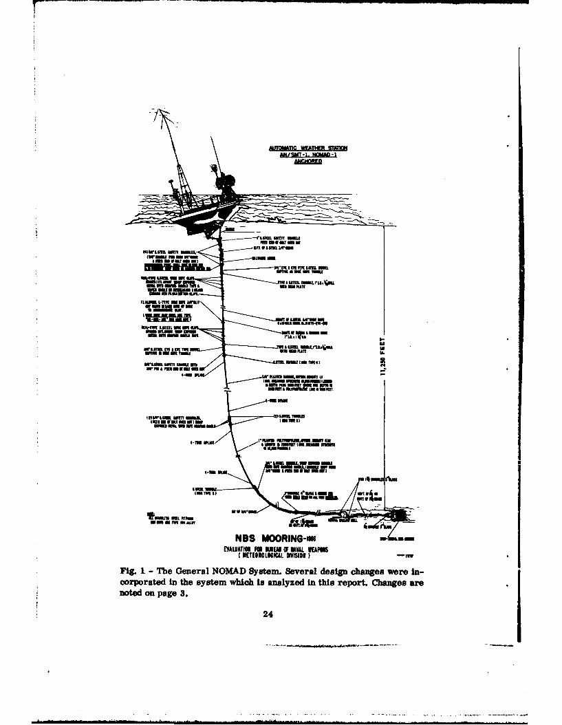
The particular NOMAD Buoy System considered here was an automaticweather station anchored in 11,250 feet of water at latitude 25-OONand longitude 90-OOW in the Gulf of Mexico. This installation wasunder the cognizance of the Naval Weapons Quality Assurance Office,Meteorological Instrumentation Division, QAO-56. The general NOMIADsystem is shown in Fig. 1. The buoy had nominal dimensions of 20x10x8feet, a displacement of 10 tons and a loaded draft of 7 feet. It wasfabricated from 6061-T6 aluminum and was initially isolated from themooring with phenolic insulators.
Several changes were incorporated in the particular system whichwas installed and is damage-analyzed in this report. Changes areunderlined within the following sentences. A 1250-foot length of 304stainless steel wire rope of 0.75-inch diameter and 6x19 Warrington,independent wire-rope core, (IWRC) 7x7 construction was connected tothe 15-foot length of stainless steel chain at the upper end of thecomposite moor line shown in Fig. 1. Connections were made to thischain and to the synthetic line at the lower end of the steel ropewith appropriate stainless steel thimbles and cable clamps. Near thebuoy an iron anode was fastened into the line just below the stainlesssteel chain by means of 0.75-inch stainless steel safety shackles.The anode was to provide cathodic protection for the stainless steelportions of the line. The lower end of the 0.75 inch stainless steelrope was covered with a single 250-foot length of neoprene Jacket ofone-inch I.D.xl.25-inch O.D. The purpose of this cover was to provideprotection against mechanical abrasion of the synthetic line in the
3
event that this line would rise towards the surface during periods ofno tension in the mooring.
After incorporation of these changes the particular system understudy was implanted and it provided 34 months of continuous serviceuntil recovery in April of 1969. The system had not failed, nor wasthere evidence of imminent failure.
INSPECTION OF THE MOORING SYSTEM
The recovered NOMAD Buoy System was made available for inspectionat the Washington Navy Yard. It had been brought here for the purposeof post-installation analysis since its useful lifetime was one of thelongest achieved at that time. Only the stainless steel portion ofthe mooring was analyzed in this study.
In initial discussions it was suggested that a corrosion analysisbe conducted by the Metallurgy Division and a mechanical damage analysisby the Ocean Technology Division of NRL. The corrosion report (I)should be studied in conjunction with this report. Cross referencesare made where these are helpful. As work proceeded in mechanical damageanalysis it quickly became apparent that mechanical effects due to corro-sion were an integral part of this study and must be included.
Sampling Procedure
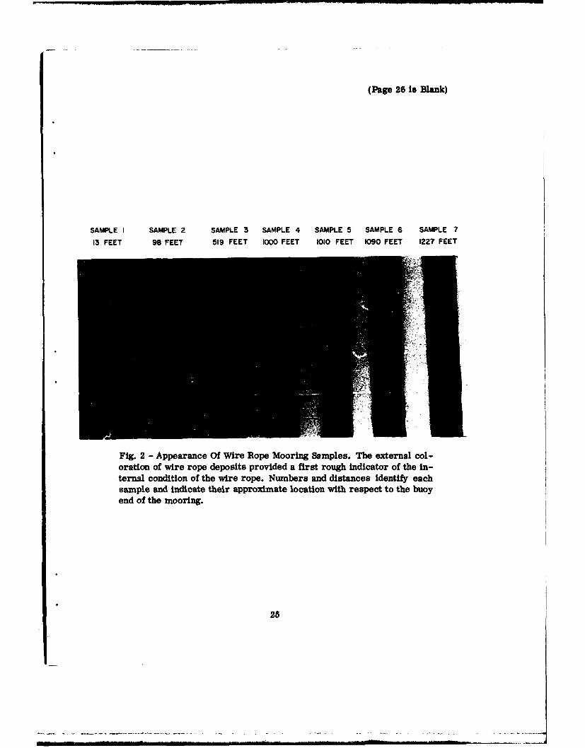
The only guidance available for choosing locations of samples forlaboratory study was the external appearance of the rope; selectionswere made upon this basis. The appearance of the rope at the chosenlocations is shown in the color photograph in Fig. 2. Prior to sampleselection, the neoprene jacket was slit over its full length and re-moved to expose the covered portion of the steel rope to view.
Following the selection of locations, wire rope samples were cutfrom the mooring line. Seven groups of adjacent 2-, 4-, and 10-footlengths were removed from the mooring. The 2-foot lengths were usedfor corrosion analysis (1) and the immediately adjacent 4-foot lengthswere used for damage analysis. It was from these 4-foot samples thatthe final specimens of 30-, 12-, and 3.5-inch lengths were obtained;these were used to provide break-strength, damage-catalog and lubricant-study data. The 10-foot samples are shown by number in Fig. 2 and theadjacent 4-foot samples are identified as to position in the rope inColumns 1 and 2 of Table I. The 10-foot samples were held in reservefor possible later use in damage analysis. For example, when need foradditional information on the condition of the rope nearer to thevertical center of the jacketed portion developed, a 4-foot specimen(6a) was cut from the appropriate 10-foot sample.
4
L- Go t- In 0 CO)
04 9 4 0 m ~ 91 4 V
M-q Cq LM eq eq e4
-j coC4C
an 0 *o e
4 -4 cm -4 ccaam) -4 $4A
100
0
0 ~ ~ 0wCD
U, N-4
U
4) 0- 0 o co 0 0 1
-4 Sq,.
0 "
uoe w e eq 0
Specimen Appearance
The external appearance of the wire rope is important and meritsdiscussion. Samples 1 through 7 in Fig. 2 will be used to illustrate
rope appearance at various locations along the mooring. The 10-footsamples shown in this photograph are identical in appearance to theadjacent 4-foot specimens except that a bend was contained in specimen3 (519'4" to 523'4")* which is not shown in samples 3 of the photograph.
The upper 104.5 feet of the rope contained a whitish deposit(samples 1 and 2). Anqlysis indicated that this deposit derived fromtwo sources. First, microscopic examination revealed a presence ofboth fibrous and crystalline structures. The fibers were not identi-
fied but some of the crystalline structures had the appearance ofalgae (silicious diatoms). This portion of the deposit is commonlyknown as marl and results from marine life decay. Second, the Metal-lurgy Division had conducted both X-ray diffraction and spectrographicanalyses of the surface products of the rope. Reference (i) notesthat when a metal is cathodically protected in sea water under certainconditions of temperature and electric potential, the protected metalwill develop white calcareous deposits (calcium and magnesium salts)on its surface. The presence of CaCO3 (calcite) as a major constituentof these deposits is reported down to the 13-foot position and as aminor constituent down to a distance of 104.5 feet. The spectrographicanalysis also indicated very strong lines for calcium, magnesium andsilicon and strong lines for aluminum at the 11- to 13-foot distance.Reference (1) concludes that the presence of aluminum and calcite inthe near-buoy portion of the wire rope indicates that the rope wasnot only being cathodically protected by the iron anode, YFeO(OH) waspresent, but also was receiving cathodic protection from the aluminumbuoy. The aluminum buoy probably was not electrically isolated fromthe mooring for at least a portion of the service period.
The mechanical condition of specimen 3 (which is not shown insample 3 of Fig. 2) should be noted. Specimen 3 contained the perma-nent bend that is illustrated by the sketch in Fig. 3. The bend isshown in its relaxed condition. This permanent deformation showed nowire breaks nor great external disarrangement of strands or strandwires. The bent cable was included in the 30-inch specimen removedfor break-strength test. Its presence introduced certain variationsin the damage data which will be discussed in a later section of thereport.
The appearance of the wire rope from approximately 100 feet to1000 feet is shown by samples 3 and 4, Fig. 2. There was an excellent
* These lengths refer to distances along the stainless steel rope,
measured from the buoy end of the rope.
6
retention of rope lubricant which imparted the dark green-to-blackdiscoloration. It is important to note the similar appearance ofsample 6, located approximately 1100 feet from the upper end of therope, and therefore 100 feet below the upper end of the 250-footneoprene jacket. It will be shown later that this portion of therope (near sample 6) was in excellent mechanical condition and wassimilar to samples 1, 2 and 4 in this regard.
The heavily rusted appearance of samples 5 and 7 is generallyindicative of the condition found in the wire rope which lay beneathand near both ends of the jacket cover. The rust did serve to indi-cate the two most heavily damaged locations in the wire rope as islater described.
In general the external mechanical condition of the rope wasexcellent. Once samples were cleared of surface lubricant and de-posits, wires and strands appeared free of any great amount of corro-sion. Some external scrape marks were visible to the naked eye onsamples 5 and 7; the significance of these is discussed later.
WIRE ROPE BREAK STRENGTH
Test Procedure
In conducting wire rope break strength tests certain precautionsregarding procedure are important. Relative displacement of wire andstrands during cutting, terminating and testing is to be avoided.There must also be a near-perfect axial alignment of terminators andrope; the spelter socket seems to offer the best opportunity forminimizing stress disturbances in the free length of rope near itsterminators. In theory, as the test machine begins to apply load,the stress distribution in wires of the rope cross section shouldbe exactly that produced by service load in the center cross sectionof an infinitely long rope. This condition is necessary if accurateand consistently reliable break strength values are to be obtained.In practice this condition is achieved, or nearly so, if at finalrupture all strand breaks have occurred simultaneously and withinthe free test rope length. Considering the complexity of the pro-cedure one generally accepts any test in which three to four strandsof a six-strand rope rupture simultaneously and all ruptures occurwithin the free length.
Additional allowance must be made during test of used cable wherenon-uniform strand damage can produce non-uniform discrepancies instrengths of individual strands. For all break strength tests on theNOMAD cable, ruptures of two or more strands occurred simultaneouslywithin the free rope length.
7
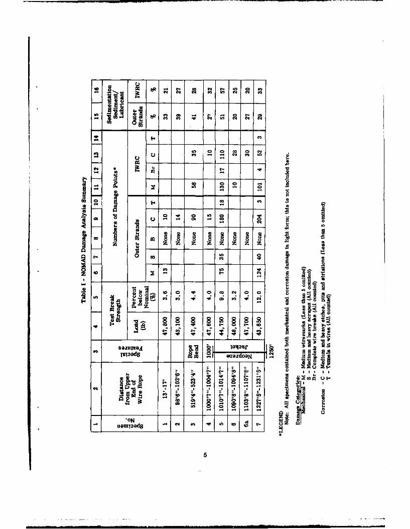
Rope break strength tests were conducted in a 60,000-lb TiniusOlsen test facility having a calibrated accuracy of better than 0.8%.The accuracy of the break strength values of the mooring line givenin column 4 of Table I are considered to be within 1% of the actualstrength of the rope, for the locations shown in column 2. The maxi-mum free test-length for rope specimens as determined by cross-headclearance in this machine was 26 inches. All NOMAD break-strengthtests were conducted with specimens having this free length.
Pre-Service Break Strength
In attempting to compute the per cent reduction in strength, con-siderable difficulty arose as to the proper selection of a base valueto represent the pre-service strength of the rope. Unfortunately norope samples had been tested prior to installation. The followingreasoning was employed to determine pre-service break strength. Themanufacturer guarantees that for any given contract a specific ropewill produce either nominal, or better than nominal, break strength.Because the manufacturing set-up process is expensive and becausethere remain certain uncertainties even for the best engineering tech-nique available, the manufacturer always sets up for a break strengthin excess of nominal. Uncertainties in wire rope manufacture wouldinclude the allowed tolerance in single-wire mechanical properties,approximations necessary to the engineering design procedure andvariations introduced by the equipment during the production run.In selecting his desired break strength, the rope engineer is facedwith two factors which contribute to reliability in manufacture.First, there is a percentage variability estimate of his own pastengineering capability in translating initial variable into a givenbreak strength goal and second, there is the estimate of what thebreak strength variability will be over the long length of completedrope. For the sake of this argument, two percentage factors of mini-mum value were assumed after discussion with a number of rope engineers.Since both of these are + 3%, it becomes obvious that the pre-manufacturedesign break-strength-goal should be the nominal strength plus 6%, andthe user may receive a finished product having a break strength up to6% over the guaranteed nominal value. However from a user standpoint,the guaranteed nominal break strength should be assumed as the workingdesign parameter since he cannot afford to destructively test the entire
mooring line before use.* The nominal strength of the 0.75-inch, 6x19(IWRC 7x7) stainless steel (304) wire rope used in this system was givenas 49,600 lbs.
* This statement is not intended to preclude strength tests on mooringlines prior to service. Such tests should always be conducted onsamples taken from locations immediately adjacent to both ends of theproposed service length of rope. There is no better way of assuringmanufacturers adherence to guarantee.
8
With these points in mind, for the NOMAD damage analysis, thenominal break strength, i.e., purchase-contract guarantee, was used asthe base in computing the percent reduction in rope strength due todamage during service. With manufacturers profit in the balance thereis a high degree of probability that the initial rope strength was nolower than the guaranteed nominal strength and therefore the computedpercent reduction in strength is a minimum and is related to the mini-mum strength that initially could occur anywhere in the rope mooring.
THE DAMAGE CATALOG
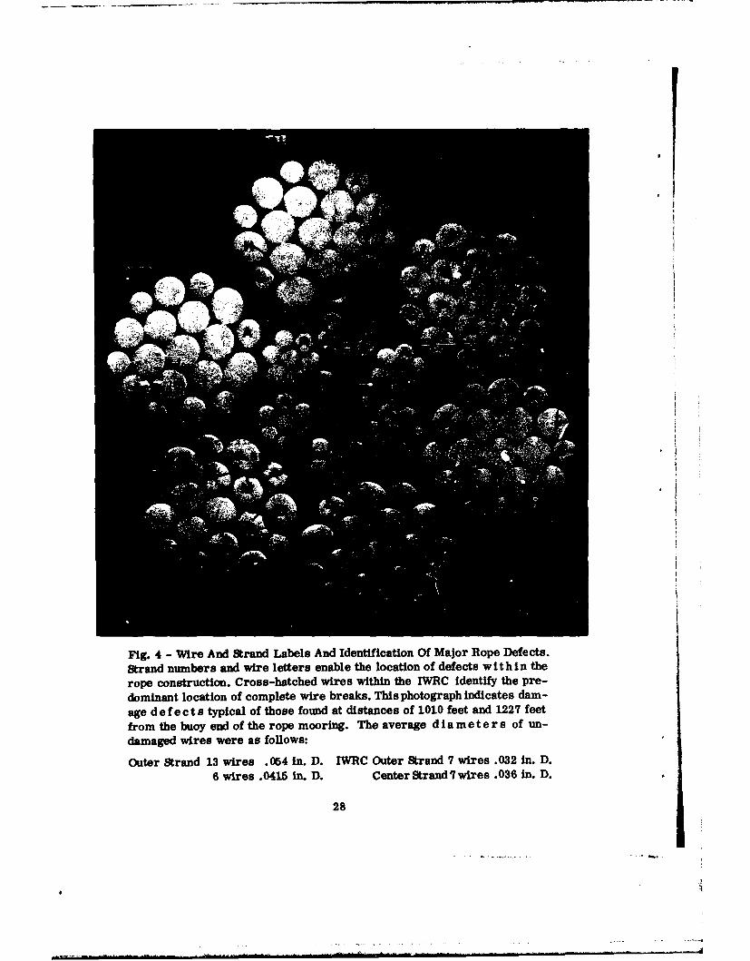
Break strength values provide a measure of the total effect ofaccumulated damage in a given length of rope. Because damage defectsreduce the effective metallic cross-sectional area of the rope, theyeffect a reduction in its break strength. Thus, large reductions inbreak strength help to locate the incidence of major damage areas alongthe moor line. However break strength studies are of little help inidentifying, locating and measuring the different damage mechanismdefects that prod4ce these accumulated effects. For this purpose onemust dismantle the rope and microscopically examine a given length ofeach wire in the construction. Since there were 163 wires in the ropecross section (Fig. 4), and a total of eight specimens for examination,some organization of the effort appeared necessary and this was suppliedby the "damage catalog".
The method of labeling the wires in a cross-section of the rope isshown in Fig. 4. Outer strands were numbered successively 1-6 and thewires in each strand were labeled alphabetically. The same procedureis used for the independent wire rope core with the prefix of 7 addedfor additional identification. The diameters of undamaged wires weremeasured in numerous locations and the averages are listed in Fig. 4.
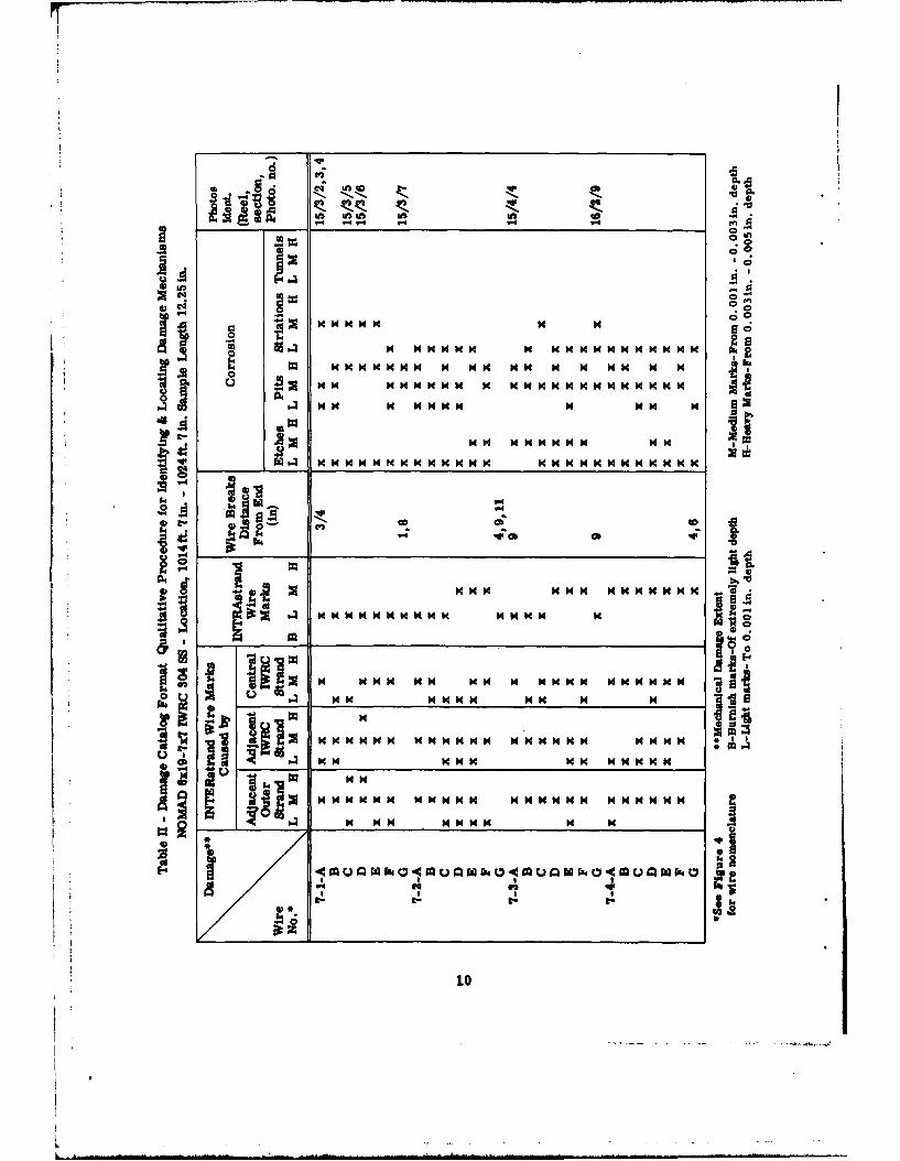
The damage catalog identifies the mechanism producing the defectobserved in a wire. One sheet from the 48-sheet NOMAD damage catalogis included as Table II to illustrate the format. Note three of themajor column headings in Table II which are laheled INTERstrand WireMarks, INTRAstrand Wire Marks and Wire Breaks. These columns identifymechanically induced defects. In a fourth major column corrosion de-fects are entered and are classified in the sub-columns headed Etches,Pits, Striations and Tunnels. The fifth major column indicates whenphotographs of the individual wires were obtained to show damage. Themeaning of the mechanical damage symbols is shown at the foot of thechart. Corrosion damage extent conforms in symbol definition to thatemployed for mechanical damage, i.e. etches, pits and striations ofLight extent would exhibit a wire penetration of up to 0.001-inch depth,Medium extent from 0.001-inch to 0.003-inch depth and Heavy extent from0.003-inch to 0.005-inch depth.
9
4)
Go M
H_ w 4 N -M
10 0
Some difficulty was encountered in establishing an optimum speci-men length. A specimen length of 12.25 inches was selected becausetrial runs on specimens cut from the extra 10-foot lengths of ropeshowed that shorter specimen lengths results in a significant loss ofwire-break counts. This specimen length of 12.25 inches includes morethan two strand lays and therefore generously covers all possible com-bined stress patterns in the wires of the rope.
A similar difficulty was encountered with selection of the numbersof strands to be counted. It was not possible to determine when acount was representative of damage if only a few strands were examined;it therefore became necessary to count all strands in each specimen.
After establishing the catalog format, locating and definingdamage defects, and fixing upon a consistent work routine the verytime-consuming task of filling out the damage catalog for the eightspecimens was completed. With respect to the eighth specimen, whichis numbered 6a in the analysis summary, Table I, it should be recalledthat this additional sample was taken from the 10-foot sample at thislocation when the surprising results for specimen 6 were revealed.This specimen (6a) provided information at a position which was a littlecloser to the mid-length location of the neoprene jacket; as noted inTable I it verifies the previous data from specimen 6 for this location.
Definition of Damage
Two kinds of photographs are available to help the reader in form-ing an opinion as to the nature of NOMAD wire rope damage. These arephotographs of the rope cross section and the more detailed photographsof individual defects.
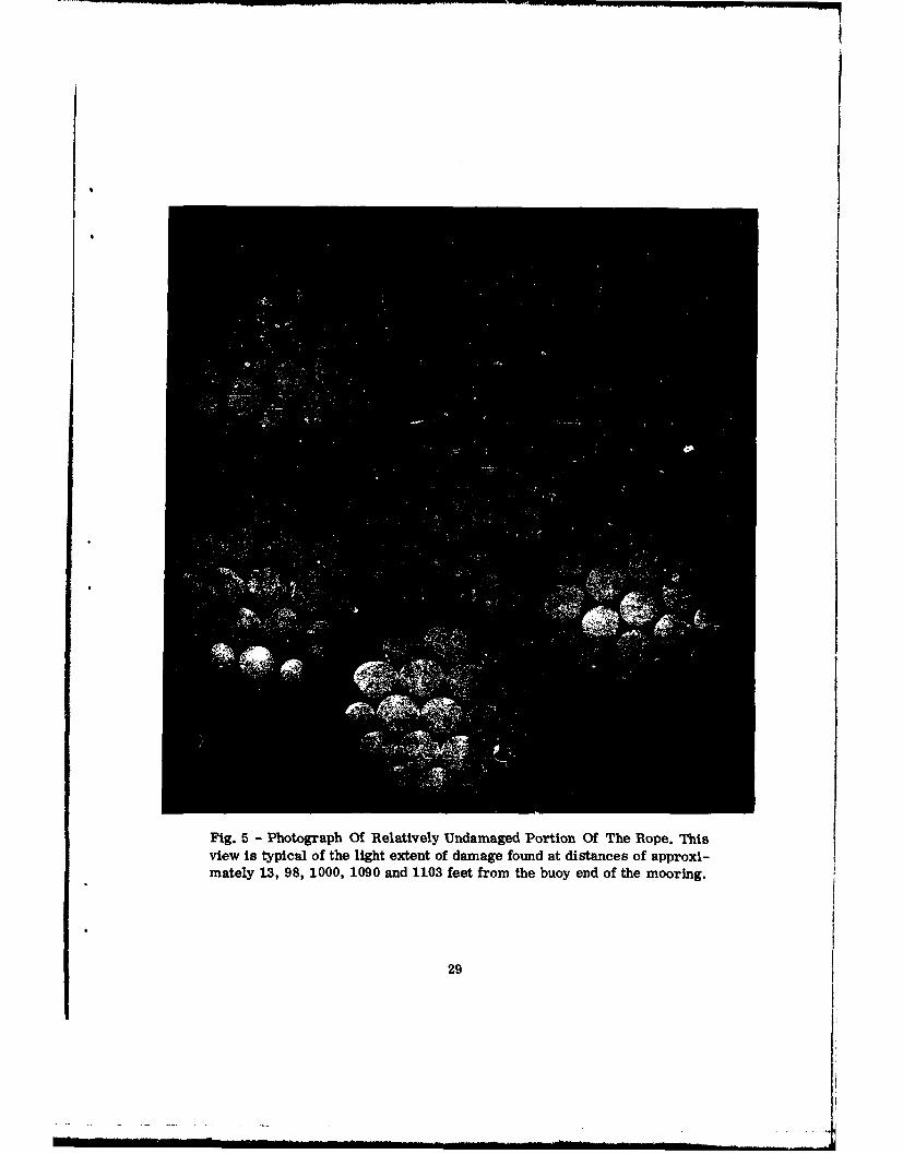
Figure 5 shows a cross section of the rope which is closely repre-sentative of the internal conditions found in specimens 1, 2, 3, 6 and6a (see Table I). There is only slight evidence of mechanical wear andabrasion and corrosive etching. No very severe damage is evident.
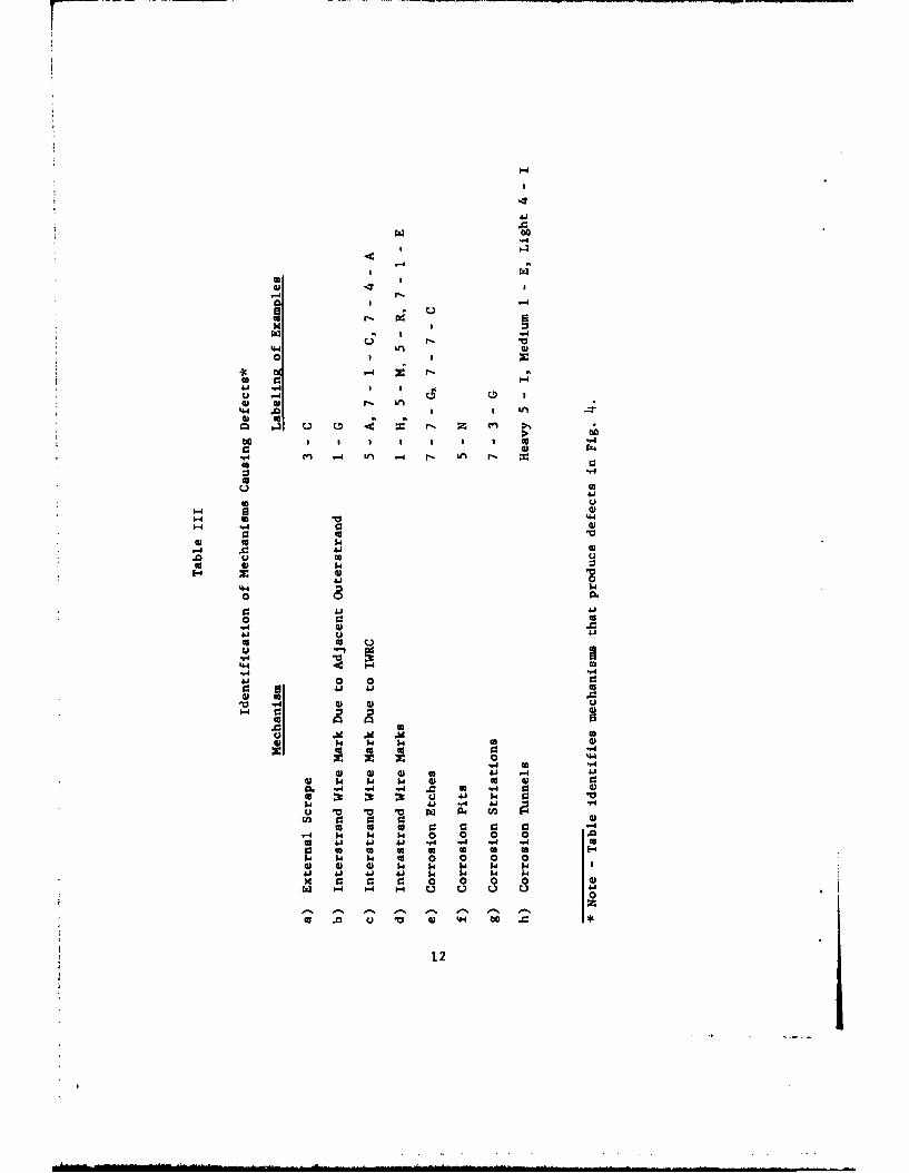
In a similar manner Fig. 4 reveals damage that is indicative ofconditions in specimens 5 and 7, and to a much lesser degree in speci-men 3. The mechanisms causing these defects are identified and locatedin Table III. In addition to the defects shown in Table III, cleansharp wire breaks occurred typically at positions 7-I-A, 7-2-G and7-7-G in Fig. 4; these breaks were observed only in specimens 5 and 7(see Table I).
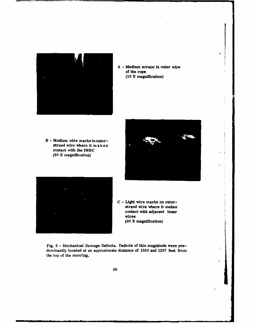
Greatly enlarged views of mechanical and corrosion defects areshown in Figs. 6, 7 and 8. Only the most severe defects are shown andthese were predominantly located either at and adjacent to the ropebend (520' 7" down from the upper end of the rope) or in those sections
11
4
LW L 0)08
44.
-d
44 .0 a
z p
I co
m. r-. A r C
4.4 L4)
-H 4 C:
* 0
.0 0
44 . a ~ r. Z c08
0
"44
4.44?A
41 0
14 4 rd0
0 0W
14 (A 04-4 4j4 414
o) 04. 4 0 o 0oL -A "4 a g 0
D4 0 $4
4.41
44 04 0
--4 0
w- w 04
0: r. c U.00
t 0 0 0 0 44 -4 4
0 1. 1. l~ 0 12
of the rope located just inside the open ends of the neoprene jacket(1010'7" to 1014'7" and 1227'5" to 1231'5").
Summary of Damage Data
After the damaW count was completed for all wires in the eightspecimens, a means of summarizing the data in a form that would revealdominant centers of damage was sought. The solution to this problemwill be found in the Nomad Damage Analysis Summary of Table I in columnstitled Damage Peaks. This condensation of damage catalog data was ob-tained by first summing all defects of like extent for the outer strandsand for the IWRC and then eliminating all defects that fell below anarbitrary standard in magnitude. Thus only defects in the medium andheavy class are retained and these are summed in columns 6 through 14 ofTable I. The summary illustrates in numberical form the location of dam-age peaks along the mooring line, (vertical traverse of columns). Or,if one selects a given position in the mooring line and scans the datahorizontally, a display of the different types of mechanism defects isavailable with numerical indication of the frequency of their occurrence.
LUBRICANT STUDY
As the study progressed, the important role of the rope lubricantbecame evident. After 34 months of exposure at sea, the wire rope moor-ing retained a large amount of lubricant over most of its length. Anexcellent quality and quantity of retained lubricant was always associ-ated with the low damage area of the mooring cable.
Curiosity about the role of the lubricant in protecting the ropeagainst mechanical and corrosion damage led to a weight and a spectro-graphical analysis of lubricant samples taken from the outer strandsand from the IWRC at each specimen location. Data from the weightanalysis is contained in columns 15 and 16 of Table I under the heading,Sedimentation. The entries represent the percent weight of sediment perunit weight of lubricant. An increase in the sediment content of thelubricant samples is generally associated with an increase in the extentof corrosion (columns 9 and 13 of Table I) as one moves from speciulen tospecimen down the mooring cable. This relationship fails at specimen 7.One would expect the sediment content for specimen 7 to be nearly thatof specimen 5. The reason for this difference is not known.
A spectrochemical analysis report of lubricant samples taken fromthe outer strands and from the IWRC at each specimen location was ob-tained. There was interest in the relative distribution of corrosionproducts within the rope and along the length of the mooring.
The results did not indicate a difference between samples takenfrom the outer strands and from the IWRC.
13
The analysis indicated the spectral density of elements associ-ated with cathodic protection of the stainless steel rope (calcium andmagnesium) as compared to the spectral density of elements derived fromits corrosion (iron and chromium) when these element-groups were viewedwith respect to their occurrence over the full length of the wire ropemoor. Very strong lines for calcium and strong lines for magnesium wereshown in all lubricant samples taken from the outer strands of specimenslocated in the uppermost 1000 feet of the wire rope mooring. The analy-sis shows that cathodic protection afforded by the iron anode extendedover the upper 1000 feet of the wire rope moor but appeared to termin-ate abruptly at the upper end of the neoprene jacket (1000 feet fromthe top of the rope). Of the elements associated with corrosion,strong to very strong lines for iron first appeared at the 520 footlevel, very strong lines appeared for chromium at the 1000-foot level,and these indications prevailed from the points noted to the lowerextremity of the rope. It is to be noted that elements associated withboth cathodic protection and corrosion appeared at a distance of 520feet down from the top of the rope, but this was also the location ofthe permanent bend in the rope. It was the presence of this mechani-cal deformation which produced corrosion in an otherwise protectedsection of the mooring. This effect will be discussed with some de-tail in a later section.
The results of the spectrochemical analysis were not sufficientlyquantitative to establish the locations of damage peaks that wereidentified in specimens 3, 5 and 7 in Table I. They reflect insteadupon the small degree of corrosion that occurred over the length ofthe mooring. These qualitative results are influenced by the relativemagnitudes of the constituents in each sample.
DISCUSSION
Work was directed towards the placement of analysis data in a formto permit ease of interpretation. Reduction and summarization of datais contained in the NOMAD Damage Analysis Summary, Table I. Before pro-ceeding with a correlation of these damage clues it is helpful to studythe geometry of the NOMAD moored buoy system and to review the forcesand motions that can exist in this system. Since not all of the designparameters of the system were available, this discussion is limited insome extent to information taken from the description of the generalNCUAD system shown in Fig. i. For the sake of brevity only obviousfacts, directly related to the damage interpretation study, will bementioned.
Throughout these preliminary discussions, and in the interpreta-tive effort to follow, attention is directed to the presence of adesign feature, the neoprene jacket, and to an installation or in-service mishap, the permanent bend in the rope.
14
Forces and Motions in the NOMAD System
Reference is made to the drawing of the general NOMAD System inFig. 1. It is important to obtain some idea of the size and geometryof this system. If instructions on the drawing are followed to ob-tain the length of the composite line from buoy to anchor, this length(23,000 feet) will be found to approximate twice the depth of theinstallation (11,250 feet). Thus if the mooring line could be straight-ened by forcing the buoy to a maximum far-left position, it would asstmea minimum angle of 300 with the surface of the sea. In practice thiscondition cannot be reached because of the gravitational forces whichact upon the massive components near the extremities of the line.
The curvature of the line when subjected to buoy load is actuallyquite complex. Each portion of the line -- wire rope, dacron, polypro-pylene and chain -- will assume a curvature in response to the forcecomponents (tension in the line -- gravitational force due to the wetmass of the line), and in accordance with its length (hydrodynamicforces neglected). The curvature will be greatest for the wire ropeand chain sections, minimal for the dacron line (density 1.4) andessentially zero for the polyprop-lene line (density 0.92). Inflec-tion points in the overall mooring will exist at each junction of dis-similar materials. An added inflection point will exist in the wirerope at the upper end of the neoprene jacket because of the added massand the stiffening effect of this jacket. The angles formed by adjacentportions of the mooring at these inflection points are important. Undervariable load these angles will change and there will be transversemotions in the moor line.
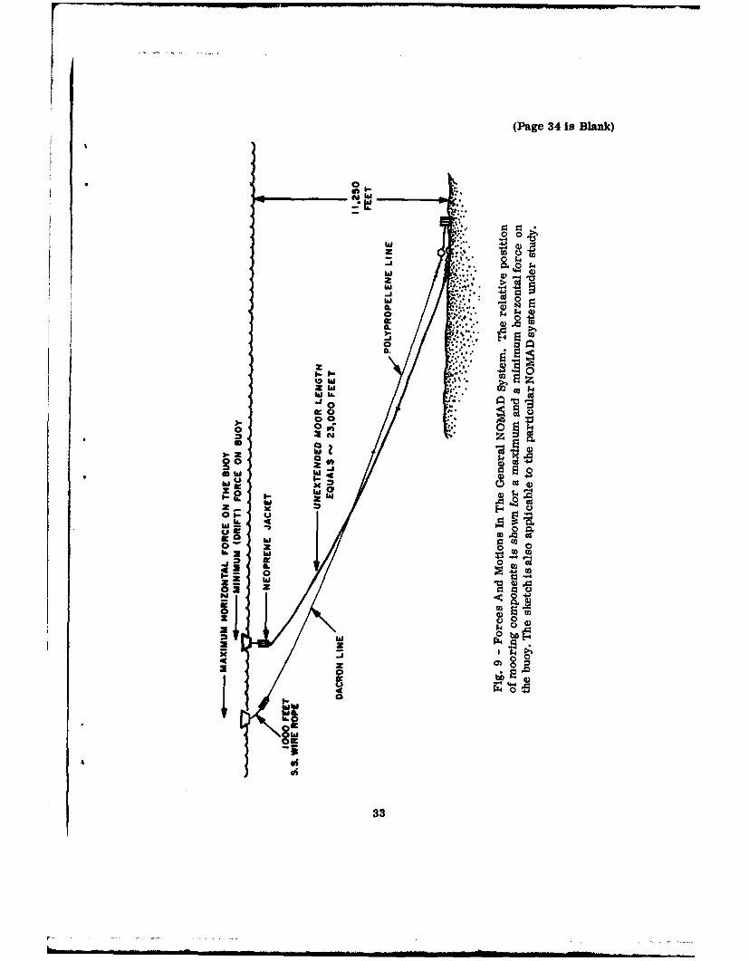
The sketches in Fig. 9 approximate the geometric shapes of thecomposite mooring line for two boundary load conditions on the buoy.For the first condition, a minimum horizontal force is applied tothe buoy. The wire rope (approximately 1000 feet) hangs in a nearvertical position and joins the dacron portion of the moor at a junc-tion angle somewhat larger than 120 degrees. The dacron and polypropyleneportions of the moor extend downward at an angle that approaches 30 0
The stainless steel chains and ballast ball lie on the sea bed. Forthe second boundary condition, a maximum horizontal force is appliedto the buoy. The wire rope rotates to assume a more in-line positionwith the remainder of the moor. There is relatively smaller changein the angular position of the synthetic portions of the line, but anincreased length because of added tension. The stainless steel chainsand ballast ball may lift off the sea bed. Thus energy added from thebuoy forces is absorbed within the mooring system through an angulardeflection of the wire rope, an extension of the mooring line compon-ents and a lifting of the chain and ballast ball. Maximum extensionsoccur in the highly elastic synthetic portions of the mooring. Thesystem is highly damped with respect to dynamic excitation of the buoy.
15
An interesting point can be made about the safety factor and theallo.able design tensile force on the rope. In Fig. 1, a minimum breakstrength of 14,000 lb is specified for the dacron line. Assuming asafety factor of three, the allowable tension in this line, and anapproximation to the tension in the lower end of the wire rope thatwas attached to it was 4670 lb. This tensile force in the wire ropemight be increased by the weight of the 1000 feet of line (-%,l000 Ib)to some 5700 lb at the upper end of the rope; thus, the minimum designsafety factor for the wire rope was about 9. The allowable staticstresses in the wire rope were low, a fact which contributed to thelong life of the installation.
Correlation of Clues
The sumnary in Table I provides a tabulation of damage analysisdata. For discussion purposes, locations along the wire rope mooringas noted in column 2 will be referred to by use of the specimen loca-tion number in column 1. Damage clues are listed below with pertinentcomments as needed.
a) A permanent bend in the rope occurred at location 3, and isdescribed in Fig. 3.
b) A neoprene jacket of 250-foot length covered the lower extrem-ity of the 1250-foot wire rope, i.e., from location 4 through 7.
c) The break strength at each of the eight locations is shown incolumn 4 of Table I. A significantly low break strength valueis indicative of a major damage area in the wire rope.
d) The percent reduction in break strength, below the nominalbreak strength of 49,600 lb, is given for each location incolumn 5. This data provides the minimum values of strengthreduction in each case. Large reductions in strength areassociated with major damage areas in the rope.
Damage peak data from the damage catalog for outer strands andIWRC are listed in columns 6 through 14. The numbers indicate thefrequency of occurrence for the particular defect in a 12.25-inchspecimen. Only medium and heavy defects are included in order toaccentuate damage peaks. The following clues seem pertinent.
e) Mechanical defects in the form of wire marks (W), external ropescrape marks (S) and complete wire breaks (B) are listed incolumns 6, 7, 8 for the outer strands and columns 11 and 12 forthe IWRC. (No external rope scrapes could occur in the IWRC).Large numbers indicate major damage areas in the wire rope.
16
f) Corrosion defects in the form of etches, pits and striations(C) and tunnel defects (T) are listed in columns 9, 10 and13, 14. Large numbers indicate major damage areas in thewire rope.
g) The percentage by weight of sediment associated with each perunit weight of lubricant is given for both outer strands andIWRC at each location in columns 15 and 16. Large percentagesof sediment are associated with major damage areas in therope.
Additional clues which could not be fitted into Table I are listedbelow.
h) The exterml appearance of the rope was of importance withrespect to the incidence of rust in the lubricant whichappeared in rope sections that lay beneath the neoprenejacket, but relatively near the open ends of this cover(locations 5 and 7 in Table I). The lubricant at these twolocations was of very poor quality, with evidence that itcontained considerable rust. It possessed little of theadhesive and cohesive properties of the lubricant evidentin all other portions of the mooring. It was granular instructure and the particles it contained (later determinedto be corrosion products) were abrasive as revealed by ascratch test.
i) The iron anode, mounted just above the top of the wire rope,had been placed there to provide cathodic protection for themooring line. Spectrochemical analysis of lubricant samplesindicated a degree of cathodic protection in the upper 1000feet of the wire rope, locations I through 4. This protec-tion did not extend to the wire rope inside the neoprenejacket.
It should now be possible to correlate these clues and to recon-struct events which led to a build-up of damage centers in the ropemoor. Alternate vertical and horizontal traverse of the data in columnsand rows of Table I provides a direct identification of the peak damagecenters in the mooring line. These damage centers are obviously lo-cated at the rope bend (location 3) and under the upper and lower endsof the neoprene jacket (locations 5 and 7). Damage associated with therope bend is small compared to damage at the other two centers.
History of Events
The origin of the permanent bend deformation in the wire rope isnot known. Three possible explanations present themselves for consider-
17
ation; one may be quickly eliminated. The possibilities of occurrence(a) during recovery, (b) during the service period or (c) during theinstallation are to be examined in turn. First, occurrence duringrecovery of the mooring system from the sea is highly improbable, be-cause a period of service in the sea was necessary to provide time forgeneration of the major mechanical and corrosion defects shown forlocation 3 in Table I. Second, occurrence during the service periodis possible. A sudden release in load, e.g., when the buoy drops offthe crest of a high amplitude wave, produces an abnormal condition inthe rates at which stored energy are released in the wire rope. Storedtensile energy can be released at a faster rate than the stored torsion-al energy with the result that a loop or bight is formed in the line.Subsequent loading will tighten the loop, i.e., reduce its diameter,and if the loop does not release in time a permanent bend deformation,or in a worse case, a kink will be produced in the line. The time ofoccurrence of this event during the service period is not known, ifthis did occur at all. If the rate of damage formation could beestablished, the time of occurrence could be determined. Finally,since a time of occurrence during the service period can not be es-tablished it is possible that the bend was present throughout thisperiod, i.e., it occurred during installation of the system. The mannerof occurrence during installation would depend upon the particular pro-cedures used and since this information is not available further dis-cussion would be futile.
The events which produce a growth in damage defects after occur-fence of a bend deformation seem fairly obvious. When a rope is per-manently deformed the strands and wires within the construction aredisarranged from their normal lay position. Subsequent cycles of loadproduce abnormal relative motion and excessive abrasive wear in unfavor-ably oriented wires. Abrasion removes the protective coating that formson the surface of stainless steel when it is cathodically protected, andit also scrapes the surface clean of its protective lubricant. The ex-posed stainless steel provides new corrosion sites and corrosive defectswill begin to appear. Corrosion products are added to the lubricant andsince these are abrasive they convert the lubricant into (literally) agrinding compound. Thus an initial deformation bend produces an unde-sirable mechanical motion and resultant mechanical abrasion clears theway for corrosion. From then on these damage mechanisms are mutuallysupportive and the processes producing degradation are accelerated.
The events leading to production of the heavy damage centers justinside the neoprene jacket mouths are not so easily reconstructed.Note in column 7 of Table I the presence of medium to heavy scrape marksin the outer wires of the rope. Note, too, the absence of scrape marksfor specimens 6 and 6a which are located near the length center of thejacket. These scrape marks (see Fig. 6A) must have been produced byrelative axial-motion (rubbing) between jacket ai'd rope. The rope isin the mooring load train Lut the jacket is not. Under cyclic load
18
the rope must move in and out of the jacket and there is indication(location of external wire scrapes) that this relative motion was largenear the jacket ends but very small near the jacket center. The possi-bility of such relative motion did not at first appear admissable.After all, with one-quarter inch of clearance available between jacketand rope one could expect the jacket to remain seated on the lower ropeclamps. Yet, the damage evidence could not be denied. Qualitativestudy of the forces and motions in the buoy system helped to removethese doubts. It is to be observed from this discussion and from thesketch in Fig. 9, that the reseating of the jacket on the lower ropeclamps is most likely to occur only for a condition of zero rope tension.With the first inception of load the wire rope (1250 feet) assumes anangular deflection from the vertical and forms a catenary curvature.With increasing load the jacketed portion of the rope approaches anangle of 300 to the horizontal plane. Internal frictional forces be-tween jacket and rope engendered by rope-jacket curvature and by trans-verse support of the jacket by the rope prevent any uniform motion ofthe whole jacket over the rope. In effect the rope under cyclic loadapparently moves in and out of both ends of the jacket with little orno relative motion near the length center of the jacket. The amount ofrope extension at each end of the jacket when a tensile load of 4000pounds is applied equals 1.60 inches. (The elastic modulus of the ropewas 14,000,000 psi and its metallic cross-sectional area was equal to0.268 square inches.)
The scrape marks are indicative of but one mode of the jacket -rope motional environment which in its totality precipitated damagein the rope. As stated in the previous discussion on forces and motionsin the NOMAD system, inflection points in the curvature of the compositemooring line will occur at the junction of dissimilar line componentsand at the upper end of the neoprene jacket. Thus inflection pointsexisted at both ends of the jacketed portion of the rope and underchanging load conditions transverse motions of the line also developedat these points. As previously noted any action which cleaned thesurface of the stainless steel of its protective coating and of itslubricant would initiate corrosion damage sites and promote a mutuallysupportive chain of degrading events. The listing of damage defectsin Table I for these two damage centers (locations 5 and 7) is proofpositive of the potency of this mechanical effect.
Extension of Service Life
A solution to the jacket and the rope bend-deformation problem areparamount to an extension of service life for the NOMAD System. It hasbeen shown that mechanical mechanisms were responsible for initiationof the degradation processes at damage centers in the wire rope portionof the NCMAD mooring line; that these mechanisms were generated througha mishap either during installation of the system or during its service
19
period, or again through the design addition of a "protective" neoprenejacket over the lower portion of the moor. It should be noted thatneither cathodic protection nor the protection afforded by the lubri-cant was effective in preventing the growth of subsequent corrosionand mechanical defects in the presence of the initiating mechanicalmechanism. In the absence of this mechanism, i.e., at the length-center of the neoprene jacket, the lubricant itself was sufficient toinhibit corrosion.
It is the prerogative of the designer to make changes in his systemand he will no doubt look to (1) more corrosive-resistive materials forhis wire rope, (2) the possibility of a close fitting extruded jacketover the entire length of the wire rope with bonding to the end termina-tions or (3) complete removal of the jacket with an increase in thedensity of the adjoining moor line component to negate need for thisappendage, and finally (4) a careful log of installation, service andrecovery procedures to institute corrections in these areas as theyappear necessary.
Prediction of Failure/Reliability
It should be noted first that this damage analysis was restrictedto the wire rope portion of the composite mooring and therefore anydiscussion of system life or reliability must be limited to this area.With this restriction in mind, it may be observed that after 34 monthsat sea this NOMAD wire rope mooring retained 88% of its initial strength.If corrections are made to eliminate the generation of damage peaks inthe mooring, the remaining ultimate strength for the same period of ser-vice, and under like environmental conditions, would be increased to 96%.It would probably be safe under these conditions to predict a servicelife of at least five to six years for this portion of the system; how-ever, such predictions will remain hazardous until the normal rate ofdegradation with respect to known service conditions can be determined.Information or data from this damage analysis study is limited to asingle data point on the reliability curve, and even this tiny bit ofinformation can not be validated with a quantitative description of theenvironment and engineering parameters that produced it.
CONCLUSIONS AND RECOMMENDATIONS
The primary objective of this initial study was to supply certaincorrective information to the designer of the NOMAD system throughdamage analysis of the wire rope portion of its mooring. Evaluation andcriticism of the procedures employed during the study were included inthe text.
The conclusions of the report may be itemized as follows:
20
1. The wire rope portion of the NG(AD mooring retained 88. ofits initial strength after 34 months at sea. With removal ofthe causative factors that initiated the principal damage centersin the mooring, this retained strength would be increased to 96%.
2. Elimination of mooring damage centers would appreciably ex-tend the service life of this wire rope component. An exact pre-diction is dependent upon a determination of the rate of degrada-tion in the mooring.
3. The generation of major damage centers resulted from twocauses, first, the presence of a wire rope deformation-bendwhich originated through mishap during the installation or in-service periods and second, the addition of a "protective" neo-prene jacket cover that was drawn over the lower end of the wirerope during system construction.
4. In each case the initiating damage mechanism was identifiedas an abnormal mechanical motion which removed the protective
coatings afforded by lubricant and cathodic protection. Subse-quent corrosion of the stainless steel generated abrasive sedi-ment in the lubricant to promote a self-supporting degradationprocess.
5. This initial study definitely indicates the large amount ofinterpretive design-analysis information which can be obtainedfrom careful damage analysis procedures.
Certain recoemendations are made in regard to the supply of support-ive information prior tothe conduct of future studies in the hope thatthese recommendations will speed future damage analysis, increase theirefficiency and reduce the subjective nature of the interpretative result.
1) Fifty-foot samples from either end of the mooring line shouldbe obtained prior to construction of the system. These samples wouldbe used for laboratory evaluations of the initial, pre-service charac-teristics of the mooring iine.
2) Specifications of the final as-constructed system, with allessential design parameters, should be supplied to the damage analyst.
3) A log of installation and recovery procedures, with specialnote made of any mishaps which occurred during these operations, isneeded.
4) A tensiometer and inclinometer should be inserted in the moor
line adjoining its uppermost extremity. Telemetered data from theseinstruments would do much towards creation of a mechanical referencefor damage rate data.
21
These recommendations also pertain to the need for a broadeningof the scope of the damage analysis study. The true worth of theanalysis can be realized only if it is included as an integral part
of the program for optimization of buoy system design and is supportedwith detailed information from all related areas.
The author wishes to thank Cdr. A. H. McCollum, former ComandingOfficer of the Naval Weapons Quality Assurance Office for his interestand assistance in making available the opportunity for conduct of thisdamage analysis of the wire rope portion of the NC4AD mooring. Theassistance and perseverance of Mr. John Bachman in performance of theexperimental work is gratefully acknowledged. The assistance of Mrs.Cathy Parrish of the Ocean Sciences Division, NRL, in performing amicroscopic examination and identification of marine life depositson the wire rope is gratefully appreciated. The author wishes tothank Mr. Samel Cress of the Metallurgy Division for performance ofthe spectro-chemical analysis, and Mr. Dean Walter of the same Division for helpful discussion and interpretation of this data. The workof Dr. R. 0. Belsheim in providing helpful discussion and review ofthe manuscript is gratefully appreciated.
22
REFERENCES
1. Lennox, T. J., Jr., "Corrosion Analysis of 304 Stainless Steel WireRope and Fittings from A Nomad Buoy Mooring System After 34-Months Con-tinuous Service in the Gulf of Mexico", NRL Memorandum Report 2045,September 1969.
2. "Preliminary Concept Formulation Summary for National Data BuoySystems", National Data Buoy Systems Project Office, Washington, D.C.,DDC Access No. AD 678 696, 1 October 1968.
3. "Pacific Sea Spider - Specifications for the Procurement of the De-
sign and Fabrication". ONR Contract Number N00014-68-C-0469, JohnGregory i, Scientific Officer, Code 485, ONR, 3 June 1968.
4. Letter 9260/5050 from Chief, Technical Division National Data BuoyDevelopment Project to Participants of Coast Guard Mooring/Hull WorkShop of 14 and 15 August 1969, dated 3 September 1969.
5. Letter from Nath, John H., to CDR. R. I. Rybacki, containing commentson Ref. (4), of 17 September 1969.
6. Nath, John H., "Dynamics of Single Point Ocean Moorings of a Buoy -A Numerical Model for Solution by Computer", Progress Report 69-10 forONR Contract No. 1286(10) Oregon State University, July 1969.
7. Skop, Richard A., "The Method of Imaginary Reactions: Applicationsto N-Point Moors", presented at Marine Technology Society, 6th AnnualConference, June 29 - July 1, 1970.
8. "Report on Oceanographic Instrumentation Deficiency Workshop", NavalOceanographic Instrumentation Center (NOIC), Washington, D.C., April 9-11,1970.
9. "Workshop on Marine Wire Rope", Catholic University of America,Washington, D. C., August 11, 12, 13, 1970.
23
IFUTHER axnONANIBUT-1, NOMAD-1
ANDMED
GOOM NOWmenwakfolm
*nw&wuLruwH)AIrLUM Wfn NINA
4warm aw 1Or01W Sam WK110 up
W.Mr.9%,40,4M LUM 1W of
W 6 ZACM0 I =1ISMWow sm.1111AW L_ MW
001110 109110a ow
0 &NK wrowWL-M LITUL I
00tworLikt u
Nrtwa M a M Tin &OWN M 10 of TOM
Wrion wm WAME on =W1110"Iff)WrOUIPWINOOF01110
4-W IRM "Min INKIMIKOWIPPI 1411KENNNOWN NWWWO
0111WIMAME INGIMPM.
(J)L4rjSM win Now Lam ToM4OWWWWOWNWINIO, IMMI)
WMWO sm W1 SM Nall
4-1=1 WM 1,PJM PKIOMMMIAM-ow ona too a "11101MANI.MWE NWNGKINOWN,
LOS 111W
101,611 IM ENSW1104-M 901 Pronamnammol
WIR111ur"161 4W.w
we -.. ,LTAL
Too. am ROOM w I lk UL0 Im In TIM 1*0 will
NOS MOORING-ionEVALUATION FOR MEAD OF NAVAL WEAPONS
I NETEONOLOCICAL DIVISION
Fig. 1 - The General NOMAD System. Several design changes were In-corporated in the system which is analyzed in this report. Changes arenoted on pop 3.
Fig. 2 - Appearance Of Wire Rope Mooring Samples. The external col-oration of wire rope deposits provided a first rough indicator of the in-ternal condition of the wire rope. Numbers and distances identify eachsample and indicate their approximate location with respect to the buoyend of the mooring.
25
1 500
8 IN. R
BEND LOCATED 520 PEET 7FROM TOP OF WIRE ROPE
Fig. 3 - Permanent Bend In 3/4in. Stainless Steel Rope. This permanentdeformation (shown in a relaxed condition) initiated internal damage in thewire rope.
27
Fig. 4 - Wire And Strand Labels And Identification Of Major Rope Defects.
Strand numbers and wire letters enable the location of defects within the
rope construction. Cross-hatched wires within the IWRC identify the pre-
dominant location of complete wire breaks. This photograph indicates dam-
age defects typical of those found at distances of 1010 feet and 1227 feet
from the buoy end of the rope mooring. The average d i a m e t e r s of un-damaged wires were as follows:
Outer Strand 13 wires .054 in. D. IWC Outer Strand 7 wires .032 in. D.6 wires .0415 in. D. Center Strand 7wires .036 in. D.
28
Fig. 5 - Photograph Of Relatively Undamaged Portion Of The Rope. This
view is typical of the light extent of damage found at distances of approxi-mately 13, 98, 1000, 1090 and 1103 feet from the buoy end of the mooring.
29
I,
A - Medium scrape in outer wireof the rope(10 X magnification)
B - Medium wire marks in outer-strand wire where it m a k e scontact with the IWRC(30 X magnification)
C - Light wire marks on outer-strand wire where it makescontact with adjacent innerwires(30 X magnification)
IFig. 6 - Mechanical Damage Defects. Defects of this magnitude were pre-dominantly located at an approximate distance of 1010 and 1227 feet fromthe top of the mooring.
30
II
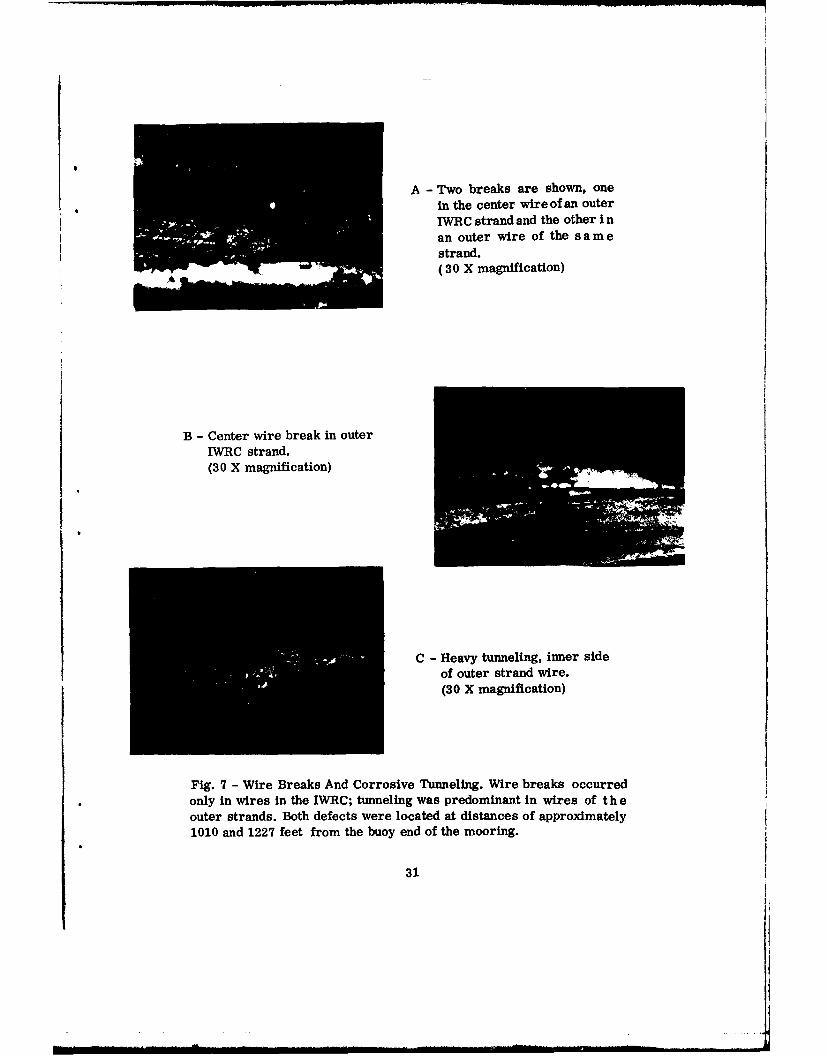
Two breaks are shown, onein the center wire of an outer
IWRC strand and the other i nan outer wire of the s a m estrand.(30 X magnification)
B - Center wire break in outerIWRC strand.(30 X magnification)
C - Heavy tunneling, inner sideof outer strand wire.(30 X magnification)
only in wires in the IWRC; tunneling was predominant in wires of the
outer strands. Both defects were located at distances of approximately1010 and 1227 feet from the buoy end of the mooring.
31
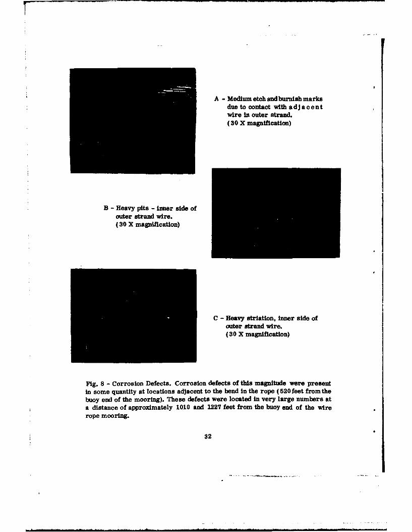
A - Medium etch and burnish marksdue to contact with adjacentwire in outer strand.(30 X magnification)
B - Heavy pits - inner side of
outer strand wire.(30 X magnification)
C - Heavy striation, inner side ofouter strand wire.(30 X magnification)
Fig. 8 - Corrosion Defects. Corrosion defects of this magnitude were presentin some quantity at locations adjacent to the bend in the rope (520feet fromthebuoy end of the mooring). These defects were located in very large numbers ata distance of approximately 1010 and 1227 feet from the buoy end of the wirerope mooring.
32
(Page 34 is Blank)
* 0
1*.
o0o 1ha .W4
z ..
04or*: 0~
-~0
0
o 0,c .0
3w 4)
00 29)
mW W
U 5 '04U0 19
4. 0
0- a a
z Ah i i 8 0w b!
33
UNCLASSIFIEDSecuntV Classificaton
DOCUMENT CONTROL DATA - R & DSe'u-r-y rlemn,,rc on O1 title, body .1 abaitart aId ndexing annotation ru-1 be entered when the Omerall report Is claliled)
I ORIGINA TING ACTI VI Tv (Corporaie altho) 2a. REPORT SECURITY CLASSIFICATION
Naval Research Laboratory UNCLASSIFIEDWashington, D.C. 20390 2b. GROUP
3 REPORT TITLE
DAMAGE ANALYSIS OF THE WIRE ROPE FROM A 34-MONTH OCEAN MOORING
4. DESCRIPTIVE NOTES (Type of report and incluaive dares)
This is an interim report.S. AUTHOR(S) (Flrt name, middle initial. lest name)
Rendler, Norbert J.
0. REPORT DATE To. TOTAL NO. OF PAGES 7b. NO. OF REFS
October 1970 40a. CONTRACT OR GRANT NO. Sa. ORIGINATOR'S REPORT NUMBERS)
NRL Problem 84F02-23h. PROJECT NO NRL Memorandum Report 2196
RR09-03-45-5806C. .b. OTHER REPORT NO(SI (Any othernumbero that may be aeijned
this report)
d.
10. DISTRIBUTION STATEMENT
This document has been approved for public release and sale; its distribution is unlimited.
It. SUPPL.EMENTA R ( NOTES %2. SP,14SORHG MILtlART AC'TIVITY
Department of the NavyI (Office of Naval Research)_ Arlington, Virginia 22217
13. ABSTRACT
Damage analysis of samples from a 304 stainless steel rope was conducted to de-termine the extent and origin of damage mechanism defects and to measure their acumu-lated effect upon mooring line break strength. The rope was located in the upper portion ofthe NOMAD buoy mooring line and had been subjected to 34 months of continuous immer-sion in the Gulf of Mexico. The primary objective of this initial study was to supply correc-tive information leading towards an extension of service life.
Damage defects of mechanical and electrochemical origin were identified and locatedin the 1250-foot length of wire rope mooring. A study of these defects revealed a specificpattern of degradation. Dominant centers of damage were associated with a wire ropedeformation-bend and with a "protective" neoprene jacket cover. In each case the initiatingdamage mechanism was identified as an abnormal mechanical motion which removed theprotective coatings afforded by lubricant and cathodic protection. Subsequent corrosion ofthe stainless steel generated an abrasive sediment in the lubricant to promote a self -supporting degradation process. The wire rope retained 88% of its initial break strength.Elimination of the causes that initiated abnormal mechanical motion would increase thisretained strength to 96%. ,
This study indicates th6 need to properly use post-service damage analysis in optimiz-ation of buoy system design. A complete understanding of usage effects in terms of failure/reliability will depend upon continued damage analysis during several protype installations.