A THESIS SUBMITTED IN PARTIAL FULFILLMENT OF THE REQUIREMENTS FOR THE DEGREE OF Bachelor in TechnologyInMetallurgical and Materials EngineeringByK.SHILPAThe present experimental study aims at assessing the different effectsof the varying environments on the mechanical properties of FRP composites. The mechanicalperformance of a composite material is decisively controlled by the state of fiber-matrixinterface . Its properties influence the integrity of composite behavior because of its role intransferring stress between the fiber and the matrix. The factors affecting the interface are toocomplex to be precisely concluded. Fibrous composites are increasingly being used in manycasual as well as critical applications owing to various desirable properties including highspecific strength, high specific stiffness and controlled anisotropy. But unfortunately polymericcomposites are susceptible to heat and moisture when operating in changing environmentalconditions.
81
DAMAGE AND DEGRADATION STUDY OF FRP COMPOSITE A THESIS SUBMITTED IN PARTIAL FULFILLMENT OF THE REQUIREMENTS FOR THE DEGREE OF Bachelor in Technology In Metallurgical and Materials Engineering By K.SHILPA Roll No: 10604037 GLORIYA PANDA Roll No: 10604040 KUMARI MAMTA Roll No: 10604016 Under the guidance of PROF. B.C. RAY Department of Metallurgical and Materials Engineering National Institute of Technology Rourkela 2010
Transcript
DAMAGE AND DEGRADATION STUDY OF
FRP COMPOSITE A THESIS SUBMITTED IN PARTIAL FULFILLMENT OF THE REQUIREMENTS FOR THE DEGREE OF
Bachelor in Technology In
Metallurgical and Materials Engineering
By
K.SHILPA Roll No: 10604037
GLORIYA PANDA Roll No: 10604040
KUMARI MAMTA Roll No: 10604016
Under the guidance of
PROF. B.C. RAY
Department of Metallurgical and Materials Engineering National Institute of Technology
Rourkela 2010
Rourkela 2010
National Institute of Technology Rourkela
CERTIFICATE This is to certify that the thesis entitled, “Damage and Degradation Study of FRP Composites” submitted by K.Shilpa (10604037), Gloriya Panda (10604040) and Kumari Mamta (10604016) in partial fulfillment of the requirements for the award of Bachelor of Technology Degree in Metallurgical and Materials Engineering at the National Institute of Technology, Rourkela (Deemed University) is an authentic work carried out by them under my supervision and guidance. To the best of my knowledge, the matter embodied in the thesis has not been submitted to any other University / Institute for the any Degree or Diploma. Date:
Prof. B.C.RAY Dept. of Metallurgical and Materials Engineering
National Institute of Technology Rourkela‐769008
ACKNOWLEDGEMENT
We take this opportunity as a privilege to thank all individuals without whose support and guidance we could not have completed our project in the stipulated period of time.
First and foremost we would like to express our deepest gratitude to our Project
Supervisor Prof. B.C.Ray, Metallurgical & Materials Engineering Department, N.I.T Rourkela for his invaluable support, guidance, motivation and encouragement throughout the period this work was carried out. His readiness for consultation at all times, his educative comments and inputs, his concern and assistance even with practical things have been extremely helpful.
We are sincerely grateful to Prof. B.B. Verma, Head of the Department, Metallurgical & Materials Engineering, for providing valuable departmental facilities. We would like to extend our sincere thanks to our project coordinators Prof.A.K.Panda and Prof. M.Kumar for helping us at each and every step in bringing out this report.
We wish to record our gratitude to Mrs. A.Mallik for her valuable suggestions and help during this project.We are highly indebted to Mr. S. Hembram, Mr. Rajesh Pattnaik, and Mr. Sameer Pradhan for their immense support and help rendered while carrying out our experiments, without which the completion of this project would have been at stake. We are highly obliged to extend our thanks to Mrs. Renuprava Dalai and Ms. Sanghamitra Sethi during the course of the entire project.
We would also like to thank all professors and lecturers, and members of the department of Metallurgical & Materials Engineering for their generous help in various ways for the completion of this thesis. K.SHILPA (10604037) GLORIYA PANDA (10604040) KUMARI MAMTA (10604016) B.TECH Metallurgical and Materials Engineering
TABLE OF CONTENTS Abstract
CHAPTER 1
INTRODUCTION 1
1.1 FRP Composite 1 1.2 Fibre reinforcement 4
1.2.1 Glass Fibre 4 1.2.2 Carbon Fibre 7
1.3 Types of matrix 8 1.3.1 Epoxy Resin 8
1.4 Applications 9 1.5 Mechanical and other properties 11
1.5.1 Density 11 1.5.2 Strength 11 1.5.3 Stiffness 12 1.5.4 Coefficient of Thermal Expansion 12 1.5.5 Electrical Conductivity 12
3.6 Effect of Sea and Distilled water 3.6.1 Introduction 53 3.6.2 Experimental Procedure 55 3.6.3 Result and Discussion 56 3.6.4 SEM Analysis 57
CHAPTER 4
SCOPE FOR FUTURE WORK 58
REFERENCES
ABSTRACT
The present experimental study aims at assessing the different effects of the varying environments on the mechanical properties of FRP composites. The mechanical performance of a composite material is decisively controlled by the state of fiber-matrix interface . Its properties influence the integrity of composite behavior because of its role in transferring stress between the fiber and the matrix. The factors affecting the interface are too complex to be precisely concluded. Fibrous composites are increasingly being used in many casual as well as critical applications owing to various desirable properties including high specific strength, high specific stiffness and controlled anisotropy. But unfortunately polymeric composites are susceptible to heat and moisture when operating in changing environmental conditions. Samples of several Glass-Epoxy composites were manufactured using the traditional hand layup method where the stacking of the plies were alternate and the weight fraction of fiber and matrix was kept at 40-60%.Specimens were cut according to the ASTM D 2344-84(1989) standards. Some of the specimens were kept in the As-cured condition so as to obtain the base properties. Experimental studies have been carried out to study the effects of thermal ageing, liquid nitrogen temperature, thermal shocks, sea and distilled water. Also, tests have been performed to study the effect of ultraviolet rays and microwave conditions on the mechanical behavior of Glass-epoxy composites. The specimens were divided into groups. One group was subjected to cryogenic conditions at -750C for 3 hours and 6 hours. Another group was subjected to elevated temperature at +750C for 5 hours and 10 hours. A separate group samples were immersed in the two mediums separately namely sea water , distilled water at their boiling temperatures .Of the remaining samples a group of samples were kept in a microwave oven for 60 , 90 and 120 secs. whereas the other part of it was kept in a ultraviolet chamber for a period of 100 hrs. Thermal shocks of two types, up-cycle (lower to higher temperature immersion) and down-cycle (higher to lower temperature immersion) were applied The aged samples were subjected to 3-point short beam shear tests. The tests were performed at room temperature with 1 mm/min and 500 mm/min crosshead speeds. The weakening effects were sensitive to loading rate. The ILSS(shear strength) values were then compared with the base values of as cured specimen SEM analysis was done to ascertain the mode of failure.
CHAPTER 1
INTRODUCTION
A COMPOSITE MATERIAL is a macroscopic combination of two or more distinct materials, having a recognizable interface between them. However, as a common practical definition, composite materials may be restricted to emphasize those materials that contain a continuous matrix constituent that binds together and provides form to an array of a stronger, stiffer reinforcement constituent. The resulting composite material has a balance of structural properties that is superior to either constituent material alone. Composites are commonly classified at two distinct levels. The first level of classification is usually made with respect to the matrix constituent. The major composite classes include organic‐matrix composites (OMCs), metal‐matrix composites (MMCs), and ceramic‐matrix composites (CMCs) .The second level of classification refers to the reinforcement form—particulate reinforcements, whisker reinforcements, continuous fiber laminated composites, and woven composites (braided and knitted fiber architectures are included in this category. In order to provide a useful increase in properties, there generally must be a substantial volume fraction (~10% or more) of the reinforcement. A particulate reinforcement is considered to be a “particle” if all of its dimensions are roughly equal. Thus, particulate‐reinforced composites include those reinforced by spheres, rods, flakes, and many other shapes of roughly equal axes. Whisker reinforcements, with an aspect ratio typically between approximately 20 to 100, are often considered together with particulates in MMCs. Together, these are classified as discontinuous” reinforcements, because the reinforcing phase is discontinuous for the lower volume fractions typically used in MMCs.
FRP Composites‐ FRP composites are defined as the materials that consist of fibers embedded in a
resin matrix. The aim of combining fibers and resins that are different in nature is to take advantage of the distinctive material features of either component to result in an engineered material with desired overall composite action for specific applications. Continuous fiber‐reinforced composites contain reinforcements having lengths much greater than their cross‐sectional dimensions. Such a composite is considered to be a discontinuous fiber or short fiber composite if its properties vary with fiber length. On the other hand, when the length of the fiber is such that any further increase in length does not, for example, further increase the elastic modulus or strength of the composite, the composite is considered to be continuous fiber reinforced. Most continuous fiber (or continuous filament) composites, in fact, contain fibers that are comparable in length to the overall dimensions of the composite part. As shown in Fig. 1, each layer or “ply” of a continuous fiber composite typically has a specific fiber orientation direction. These layers can be stacked such that each layer has a specified fiber orientation, thereby giving the entire laminated stack (“laminate”) highly tailorable overall properties.[1]
Engineering properties of FRP composites for structural applications, in most cases ,are dominated by fiber reinforcements. More fibers usually give rise to higher strength and stiffness. Excessively high fiber/matrix ratios may ,however, lead to strength reduction or premature failure due to internal fracture. Fiber lengths and orientation also affect the properties considerably. Resin matrix is an adhesive that supports the fibers from buckling under compressive stress ,binds the fibers together through cohesion and adhesion ,protects the fibers from physical and chemical attacks and micro‐cracking during service, and provides shearing strengths between FRP laminas. Shearing strength is essential to resist delamination , lap joint failure and impact forces. Structural FRP composites are generally high strength , reasonably stiff environmentally resistant and significantly lighter than conventional construction materials such as concrete and steel. Choice of particular types of fibers and resins depends on the specific applications. Load‐bearing capacity, level of exposure , wear resistance , temperature and frequency ranges , fire and water resistance and costs are some of the important issues that need to be thoroughly considered. Various advantages of composite materials are its high specific stiffness and high specific strength. These properties are generally used in structural application such as aerospace and sporting goods [2].
2.1 FIBER REINFORCEMENT : Reinforcement materials A great majority of materials are stronger ad stiffer in fibrous form than as bulk materials. A high fibre aspect ratio (length: diameter ratio) permits very effective transfer of load via matrix materials to the fibres, thus taking advantage of there excellent properties. Therefore, fibres are very effective and attractive reinforcement materials. Types of fibers used in fibre reinforced polymer composites Glass fibres Carbon fibres 2.1.1. GLASS FIBERS: The most common reinforcement for the polymer matrix composites is a glass fibre. Most of the fibres are based on silica (SiO2), with addition of oxides of Ca, B, Na, Fe, and Al. The glass fibres are divided into three classes ‐‐ E‐glass, S‐glass and C‐glass. The E‐glass is designated for electrical use and the S‐glass for high strength. The C‐glass is for high corrosion resistance, and it is uncommon for civil engineering application. Of the three fibres, the E‐glass is the most common reinforcement material used in civil structures. It is produced from lime‐aluminaborosilicate which can be easily obtained from abundance of raw materials like sand. The glass fibre strength and modulus can degrade with increasing temperature. Although the glass material creeps under a sustained load, it can be designed to perform satisfactorily. The fibre itself is regarded as an isotropic material and has a lower thermal expansion coefficient than that of steel. • Eglass (electrical) Family of glassed with a calcium aluminum borosilicate composition and a maximum alkali composition of 2%. These are used when strength and high electrical resistivity are required. • Sglass (tensile strength) Fibres have a magnesium alumino‐silicate composition, which demonstrates high strength and used in application where very high tensile strength required. • Cglass (chemical) It has a soda lime borosilicate composition that is used for its chemical stability in corrosive environment. It is often used on composites that contain or contact acidic materials [3]. .
Table1.3. Composition of E‐Glass
Typical Properties
E Glass SGlass
Density (g/cm3)
2.60 2.50
Young's Modulus (GPa) 72 87
Tensile Strength (GPa) 1.72 2.53
Tensile Elongation (%) 2.4 2.9
2.1.1.1. Structure of glass fibre Glass fibres have high tensile strength, impact strengths and high chemical resistance. But these have relatively low modulus, self‐abrasiveness, low fatigue resistance and poor adhesion to matrix composites
Constituent
Weight percentage
SiO2
54
Al203
14
CaO+MgO
12
B2O3
10
Na2O+K2O
Less than 2
Impurities
Traces
The three dimensional network of structure of glass results in isotropic properties of glass fibres, in contrast to those of carbon and Kevlar aramid fibres which are anisotropic. The elastic modulus of glass fibres measured along the fibre axis is the same as that measured in the transverse direction, a characteristic unique to glass fibres. 2.1.1.2. Surface Treatment of Reinforcing Materials Surface treatment is done to improve the adhesion of fillers and fibres to matrix resin by modifying the surface of the solid. Often, chemical structure and sometimes topology of the surface change upon the treatment. Chemistry of Surface Treatment and Interfacial Structure Glass Fibres and Inorganic Fillers Inorganic materials like glass fibres and many fillers have poor compatibility at the fibre/matrix or filler/matrix interface. In order to improve adhesion at the interface, compounds with dual property, i.e. molecules having chemical functionalities similar to the fibre and the matrix resin, are used. Due to the coupling action of the fibre and the resin by the compatibilizing compound, this type of compound is often referred to as a coupling agent, such as a silane coupling agent. In addition to the adhesion promotion, coupling agents aid in protecting fibre surfaces and prevent inhibition of polymerization by the solid surfaces. A small amount of a coupling agent can often dramatically improve the mechanical and physical properties of composites. [4].
Fig.1. Chemical process during surface treatment silaceous material by a silane coupling agent. Regardless of the treatment methods, the silane loses its alkoxy groups and chemically reacts with the hydroxyl groups of the mineral surfaces
2.1.2. Carbon fibres Carbon fibre is the most expensive of the more common reinforcements, but in space applications the combination of excellent performance characteristics coupled with light weight make it indispensable reinforcement with cost being of secondary importance. Carbon fibres consist of small crystallite of turbostratic graphite. In a graphite single crystal the carbon atoms in a basal plane are arranged in hexagonal arrays and held together by strong covalent bonds. Between the basal planes only weak Van‐der‐waal forces exist. Therefore the single crystals are highly anisotropic with the plane moduli of the order of 100 GPa whereas the molecules perpendicular to the basal plane are only about 75 GPa. It is thus evident that to produce high modulus and high strength fibres, the basal planes of the graphite must be parallel to the fibre axis. They have lower thermal expansion coefficients than both the glass and aramid fibres. The carbon fibre is an anisotropic material, and its transverse modulus is an order of magnitude less than its longitudinal modulus. The material has a very high fatigue and creep resistance. Since its tensile strength decreases with increasing modulus, its strain at rupture will also are much lower. Because of the material brittleness at higher modulus, it becomes critical in joint and connection details, which can have high stress concentrations. As a result of this phenomenon, carbon composite laminates are more effective with adhesive bonding that eliminates mechanical fasteners [5].
Table1.5. Typical properties of Carbon Fibre
Typical Properties
Density (g/cm3)
Young's Modulus (GPa)
Tensile Strength (GPa)
Tensile Elongation (%)
High Strength
1.8 230 2.48 1.1
High Modulus
1.9 370 1.79 0.5
Ultra‐High Modulus
2.0 ‐ 2.1 520 – 620 1.03 ‐ 1.31 0.2
2.2 Types of Matrix phase used in fibre reinforced polymer composites Fibres, since they cannot transmit loads from one to another, have limited use in engineering applications. When they are embedded in a matrix material, to form a composite, the matrix serves to bind the fibres together, transfer loads to the fibres, and damage due to handling. The matrix has a strong influence on several mechanical properties of the composite such as transverse modulus and strength, shear properties, and properties in compression.. Commonly used matrix materials are described below: 2.2.1. Epoxy resin Epoxy resins are relatively low molecular weight pre‐polymers capable of being processed under a variety of conditions. Two important advantages of these resins are over unsaturated polyester resins are: first, they can be partially cured and stored in that state, and second they exhibit low shrinkage during cure. Approximately 45% of the total amount of epoxy resins produced is used in protective coatings while the remaining is used in structural applications such as laminates and composites, tooling, moulding, casting, construction, adhesives, etc [3]. Epoxy resins are characterized by the presence of a three‐membered ring containing two carbons and an oxygen (epoxy group or epoxide or oxirane ring). Epoxy is the first liquid reaction product of bisphenol‐A with excess of epichlorohidrin and this resin is known as diglycidylether of bisphenol A (DGEBA). DGEBA is used extensively in industry due to its high fluidity, processing ease, and good physical properties of the cured of resin.
Ethylene diamines are most widely used aliphatic amines for cured epoxy resins. These are highly reactive, low molecular weight curing agents that result in tightly cross‐linked network. One primary amino group reacts with two epoxy groups. The primary and secondary amines are reactive curing agents. The primary amino group is more reactive towards epoxy than secondary amino groups are consumed (95%), whereas only 28% of secondary amino groups are consumed.
The primary amino‐epoxy reaction results in linear polymerization while secondary amino‐epoxy reaction leads to branching and cross‐linking. The cured epoxy resins find a variety of applications as adhesives, laminates, sealants, coatings, etc. The optimum curing temperature and the thermal stability of epoxy resin depend on the type of curing agent. Epoxies are used as binders in materials for construction. Filling of cracks in concrete structures is achieved by epoxies. In construction industry, for bonding and coating purposes, low temperature curing of epoxies is achieved by using thiols that exhibit higher curing rates. 3. APPLICATIONS: The composites industry has begun to recognize that the commercial applications of composites promise to offer much larger business opportunities than the aerospace sector due to the sheer size of transportation industry. Thus the shift of composite applications from aircraft to other commercial uses has become prominent in recent years [6]. Increasingly enabled by the introduction of newer polymer resin matrix materials and high performance reinforcement fibres of glass, carbon and aramid, the penetration of these advanced materials has witnessed a steady expansion in uses and volume. The increased volume has resulted in an expected reduction in costs. High performance FRP can now be found in such diverse applications as composite armouring designed to resist explosive impacts, fuel cylinders for natural gas vehicles, windmill blades, industrial drive shafts, support beams of highway bridges and even paper making rollers. For certain applications, the use of composites rather than metals has in fact resulted in savings of both cost and weight. Unlike conventional materials (e.g., steel), the properties of the composite material can be designed considering the structural aspects. The design of a structural component using composites involves both material and structural design. Composite properties (e.g. stiffness, thermal expansion etc.) can be varied continuously over a broad range of values under the control of the designer. Careful selection of reinforcement type enables finished product characteristics to be tailored to almost any specific engineering requirement. .3.1. Composites: The Future Trends Armed with a wide gamut of advantages, composites have a key role to play in the growing market in India. Composites have made an entry into diverse end‐use segments and the developmental efforts for finding newer composites for existing and novel applications is an area of top priority. Transportation Sector Glass‐reinforced thermoplastic polymer is a promising material for weight reduction because of the relatively low cost of the fibre, its fast cycle time and its ability to facilitate parts integration. Carbon fibre reinforced polymer is another candidate but will require breakthroughs in cost and manufacturing techniques to be cost effective for high volume production.
They find applications in
Automobiles Bicycles Marine
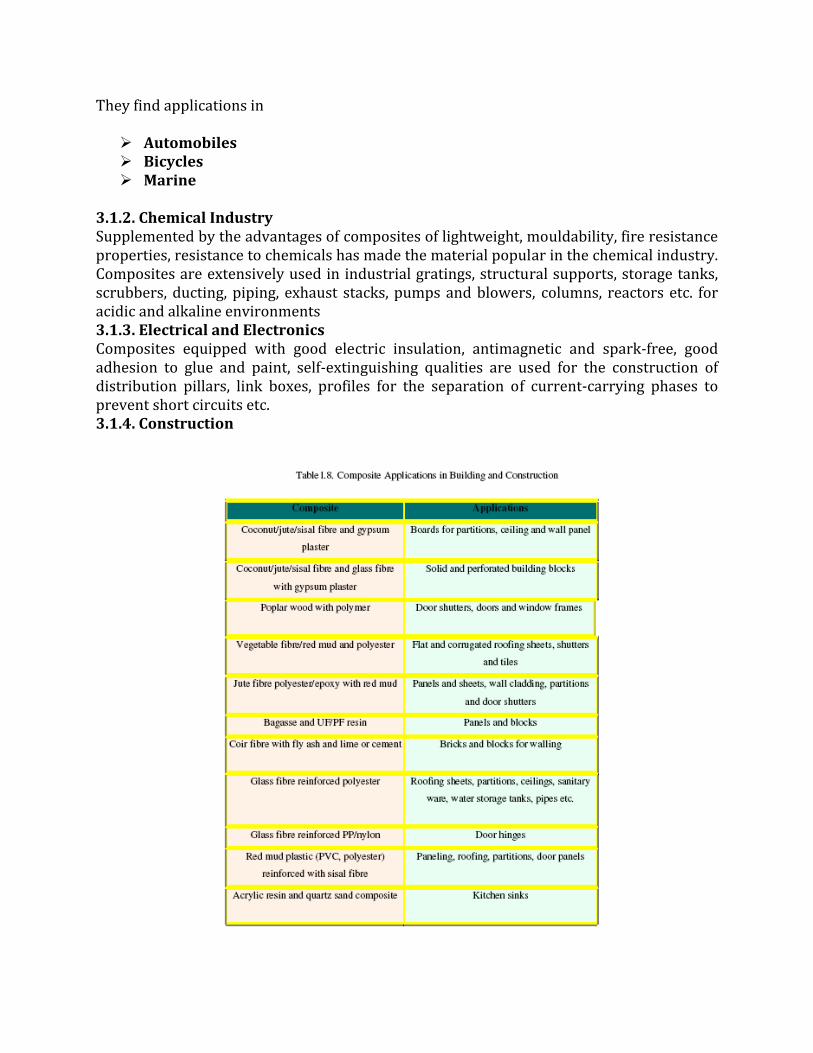
3.1.2. Chemical Industry Supplemented by the advantages of composites of lightweight, mouldability, fire resistance properties, resistance to chemicals has made the material popular in the chemical industry. Composites are extensively used in industrial gratings, structural supports, storage tanks, scrubbers, ducting, piping, exhaust stacks, pumps and blowers, columns, reactors etc. for acidic and alkaline environments 3.1.3. Electrical and Electronics Composites equipped with good electric insulation, antimagnetic and spark‐free, good adhesion to glue and paint, self‐extinguishing qualities are used for the construction of distribution pillars, link boxes, profiles for the separation of current‐carrying phases to prevent short circuits etc. 3.1.4. Construction
3.1.5. Offshore Oil and Gas Industry Steel and concrete are the materials of choice for offshore oil and gas production platforms, with steel dominant in the topside applications. Composites have found their way into limited applications, particularly where corrosion and the need to reduce high maintenance costs have been an issue. As the industry moves to greater water depths, the significance of weight saving has become increasingly important in conjunction with the application of buoyant tension for the leg structures. 3.1.6. Consumer and Sports Goods The optimum design of sports equipment requires the application of a number of disciplines, not only for enhanced performance but also to make the equipment as user‐friendly as possible from the standpoint of injury avoidance. In designing sports equipment, the various characteristics of materials must be considered. Among these characteristics are strength, ductility, density, fatigue resistance, toughness, modulus (damping), and cost. 4. MECHANICAL AND OTHER PROPERTIES
Mechanical properties of FRP composites are the weighted average of those of fibres and resins. Rule of mixtures are normally applied to estimate strength and stiffness of a FRP composite material that is composed of a particular type of fiber and resin. Owing to the relative brittleness of a FRP composites (in the fibre direction), strength values from experimental testing normally exhibit higher variance than those of other construction materials like steel. The use of the rule of mixtures or the micro‐mechanics approach does not predict strength very well. Statistical approaches such as Weibull analysis are thus required for appropriate quantification .On the contrary, stiffness values from the testing are relatively uniform and can be predicted with high accuracy using micro‐mechanics formulation.
4.1 Density
Compared to steel and concrete,FRP composites are about 1.5to 5 times lighter. For example,carbon/epoxy composites has a density of 1.6g/cm3 compared to 7.9g/cm3 of steel and 2.4g/cm3 of concrete. This lightweight characteristic not only leads to very high specific strength and specific stiffness,hence high load taking efficiency with decreased structural weight,but has also strong implication on reduced costs of transportation, handling, and construction.
4.2Strength
Tensile strength of FRP composites ranges from about that of mild steel more than that of pre‐stressing steels depending on the fibre types,arrangements,orientation,and production.While compressive strength of steel is identical to its tensile strength,the compressive strength of FRP composites is normally less than the tensile strength,which is
due to fibre buckling failure. Yet,the strengths of commercial FRP composites are tremendous compared to any conventional construction materials.In situations where high tensile and compressive strengths are considered assets such as tensile and flexural members,FRP composites offer strong incentives for use.Shear strength of all unidirectional laminates is relatively low since this parameter is mainly controlled by the strength of the resin in such FRP systems.however,for a laminate that is made up of multiple plies,fibres can be designed to the particular orientation that matches with the maximum shear stress.In such a case,shear strength is provided by the fibres ,which act in tension,instead of the resin. 4.3 Stiffness
Stiffness of FRP composites ranges widely and has strong correlation with fibre content, continuity and orientation. Glass FRP generally has lower stiffness than carbon FRP while the latter can have a magnitude from half of the stiffness of ordinary structural steel to higher than that of high strength steel. One unique feature about FRP composites is that the material exhibit linear or nearly linear stress‐strain phenomenon throughout their load carrying range, meaning that the stiffness does not change over their load history. This behavior is significantly different from that of steel and concrete in which reduction of stiffness occurs even when the applied stress has not quite yet reached the ultimate material capacity.
4.4 Coefficient of thermal expansion
Unlike all the construction materials that civil engineers are acquainted with, many FRP composites(unidirectional laminates) shrink upon temperature increase. In particular, carbon and aramid FRP have negative coefficients of thermal expansion while that of glass is positive .although resins expand upon heating, carbon and aramid fibres resist thermal expansion. The magnitude of thermal shrinkage of carbon and thermal expansion of epoxy resins is about to cancel out each other and thus give rise to an overall near‐zero coefficient of thermal expansion of carbon/epoxy FRP>this property is of great significance in terms of residual stress development in the bond interface.
4.5 Electrical conductivity
Electrical conductivity may be of great interest when provision of post‐curing is desired for the bonding adhesives so as to boost higher the glass transition temperature to prevent viscoelastic responses during the service life .In fact, some companies who provide FRP retrofit materials have started to develop electrical heating systems that can be clamped onto the FRP plates to heat up the bond interface for further curing. As such, electrical conductivity of FRP composites is a parameter that is worth looking upto.
Inspite of the fact that composites possess wide range of properties and can be used in many applications it has a major drawback i.e. during its service life as it is often subjected to environments of severe changing parameters, it undergoes degaradation. The structural integrity and life time performance of fibrous polymeric composites are strongly dependent on the stability of the fiber/polymer interfacial region. The environmental conditions, such as high moisture and high temperature can limit the usefulness of polymer composites by deteriorating mechanical properties during service.
5. THE FAILURE ANALYSIS:
Fractographic techniques can be used to study micro‐mechanisms of fracture and investigation of failure in laboratory structures. In composites the main causes of failure can be: (a) Breaking of fibers. (b) Debonding (separation of fibers &matrix). (c) Microcracking of the matrix. (d) Delamination. Fracture modes in composites can be divided into three basic fracture types
a) Interlaminar, b) Intralaminar, c) Translaminar In both interlaminar and intralaminar fracture, fracture occurs on a plane parallel to that of the fiber reinforcement. Translaminar fractures are those oriented transverse to the laminated plane in which conditions of fiber fractures are generated.
Crack opening modes
(a) DELAMINATION: Delamination is a critical failure mode in composite structures, because it can degrade the laminate to such a degree that it becomes useless in service. The interfacial separation caused by the delamination may lead to premature buckling of the laminate, excessive vibration, intrusion of moisture, stiffness degradation and loss of fatigue life [7]. The delamination in some cases may provide stress relief and actually enhance the performance of the component.
(b) FIBRE PULL OUT AND DEBONDING: At some distance ahead of the crack the fibers are intact. These fibers are broken in the highly stressed region near the crack tip. Immediately behind the crack tip fibers pull out of the matrix. The stress near the crack tip can cause the fibers to debond from the matrix before they break.
Generally it is seen that the fibers tend to snap ahead of the crack tip leaving behind bridges of matrx that neck down and fracture in a completely ductile manner.moreover, a delamination crack may also be generated when the crack propagates along the interface when it reaches the interface.
meta In metallic matrices, plastic deformation requires considerable energy and so ls are intrinsically tough. In fibre reinforced materials with both brittle fibres and brittle matrices, toughness is derived from two sources. Firstly, if the crack can be made to run up and down every fibre in its path the there will be a large amount of new surface created for a very small increase in crack area perpendicular to the maximum principal stress ‐ INTERFACIAL ENERGY ‐ and in order to get the fibres to break they have to be loaded to their fracture strength and this often requires additional local elastic work, and secondly if the fibres do not break and therefore bridge the gap then work must be done to pull the
fibres out of the matrix ‐ FIBRE PULLOUT[8]. Using simple geometric models we can estimate the contribution of each of these processes to the overall toughness of the composite.
showing a crack front
(c) MATRIX MICROCRACKING: Matrix micro cracking most often dominates the degradation mechanism in a composite. They are intralaminar in nature that traverse and run parallel to the fibres . These micro cracks are transverse to the loading direction. Micro cracks may be observed during tensile loading, during fatigue loading, during changes in temperature and during thermo cycling. The immediate effect of the micro cracks is to cause degradation in the thermo mechanical properties of the laminate including changes in all effective modules, Poisson’s ratio and thermal expansion coefficients. Another detrimental effect of the micro cracks is that they nucleate other forms of damage such as induction of delamination, fibre breakage or provide pathways for the entry of corrosive liquids. Such damage modes may subsequently lead to laminate failure
6. METHODS
SHORT BEAM SHEAR TEST:
It is one of the most popular flexural test methods. In this test the flat specimen is simply supported at the two ends and is loaded by a central load. Generally the flexural strength is obtained by measuring the applied load and corresponding strain. In this case we are obtaining the interlaminar shear stress values. The most widespread method of testing ILSS is the short span flexural test. If despite the short span to thickness ratio, the specimen fails in the flexural rather than a shear mode, the result of the test should not be reported as ILSS. Short span flexural testing is applicable to composites with unidirectional and bi‐directional reinforcement, but does not give satisfactory results with planer random and three dimensionally random short fibre composites.
ILSS = 0.75P/WT
3-Point Bending Test Setup
Where P = Breaking load W = Width of the specimen T = Thickness of the specimen. It shows the set up of three point bend test. Here the specimen is simply supported at the two ends and is loaded by a central load. Below is given the formula to obtain the ILSS value.
Instron 1195 ILSS data are often used to specify the quality of the composites. It is considered as a direct function of interfacial adhesion.
CHAPTER 2
LITERATURE SURVEY
Literature survey is the documentation of a comprehensive review of the published and unpublished work from secondary sources data in the areas of specific interest to the researcher. The library is a rich storage base for secondary data and researchers used to spend several weeks and sometimes months going through books, journals, newspapers, magazines, conference proceedings, doctoral dissertations, master's theses, government publications and financial reports to find information on their research topic. With computerized databases now readily available and accessible the literature search is much speedier and easier and can be done without entering the portals of a library building. The researcher could start the literature survey even as the information from the unstructured and structured interviews is being gathered. Reviewing the literature on the topic area at this time helps the researcher to focus further interviews more meaningfully on certain aspects found to be important is the published studies even if these had not surfaced during the earlier questioning. So the literature survey is important for gathering the secondary data for the research which might be proved very helpful in the research. The literature survey can be conducted for several reasons. The literature review can be in any area of the business.[9]
THERMAL SHOCK:
As has been studied by N.L. Hancox, on the ” Thermal effects on polymer matrix” thermal cycling involves repeatedly cycling a material a specimen between two temperatures with a sufficient dwell time at either extreme to thermal equilibrium to be attained inducing large thermal gradient through the specimen. Sudden changes in temperature act on entrapped moisture and volatiles causing freezing, condensation and or vaporization and hence internal damage. It arises due to heterogenous nature of composites and the different coefficients of thermal expansion(CTE) of the components.[10] G.C. Papanicolaou, N.K. Anifantis, L.K. Keppas and Th.V. Kosmidou, who studied the” Stress analysis of fibrereinforced polymers “. They pointed out that generally, in polymeric systems, the reinforcement has a much higher modulus, and a lower coefficient of expansion which creates a negative mismatch or induced stress at low temperatures. As the material is cooled from Tmax to Tmin, stresses develop in the polymer within the fibre–matrix interface region[11,12,13]. owing to the difference in the coefficients of thermal expansion of the two components[14] . The positive and negative temperature changes, cause large compressive and tensile stresses respectively and contribute to the fatigue of the composites in a different way[15]. Experimental work has shown that FRPs subjected to temperature fluctuations are prone to cracking, which usually appears at the free surface after only a few thermal cycles, even
for relatively small temperature differences. This high sensitivity to temperature change is attributed to the thermal stress concentration located close to the free surface of the fibre–matrix interface[16]. Matrix micro‐cracking can alter macro‐mechanical properties such as strength, stiffness and dimensional stability depending on the material type and laminate lay up. Micro‐cracks act as sites for environmental degradation as well as for nucleation for macro‐cracks. Thus, micro‐cracks can ultimately lead to material degradation and reduced performance[17].
On the other hand the studies by R.A. Latour, J. Black and B. Miller, on the” Fatigue behavior characterization of the fibre–matrix interface” said that fiber spacing is an important parameter for developing thermal stresses is . Decreased fiber spacing lead to an increase in the magnitude of the local thermal stresses and consequently to an increase in micro‐cracking. Consequently, the thermal load necessary to initiate micro‐cracking, decreases significantly with a smaller inter fiber spacing. Also, the properties of the interface region were found to significantly alter the location of the maximum stress and the initiation of micro‐cracks.
According to B.F. Boukhoulda, A. AddaBedia and K. Madani, an important factor affecting the material performance is the presence of water within the material structure. The presence of water in the resin and/or the cracks cause increased deterioration upon thermal cycling. If the water expanded within the crack during freezing, the additional stress might cause crack opening or propagation. Conversely, plasticization of the matrix by the moisture may give rise to increased toughness and hence resist crack initiation and propagation [18,19,20].From the above‐mentioned discussion it is clear that thermal fatigue is a complex phenomenon requiring continuing research efforts [21‐24].
EFFECT OF SEA WATER:
Glass fiber reinforced composites are often used in marine applications such as canoes, fishing trawlers, patrol boats and naval mine‐hunting ships and in the non‐pressure hull casing, sonar dome and masts of submarines. When used in marine applications it is essential that GFRP composites retain their mechanical properties and do not degrade when immersed in sea water for a long time. One major issue of using GFRP composites in sea water application is that the fiber/matrix interface is degraded by a hydrolysis reaction of unsaturated groups within the resin. Saud Aldajah , Ghydaa Alawsi , Safaa Abdul Rahmaan who studied on the ” Impact of sea and tap water exposure on the durability of GFRP laminates” pointed out that sea water degradation can cause swelling and plasticization of the polyester matrix and debonding at the fiber/matrix interface that may reduce the mechanical properties [25]
As per C.H. Shen and G.S. Springer who studied ”Effects of moisture and temperature on the tensile strength of composite materials”, when exposed to humid environments, polymer based composite structures can absorb moisture, which affects the long term
structural durability and properties of the composite.. Since high performance fibers absorb little or no moisture compared to the matrix, the absorption is largely matrix dominated. Moisture penetration is largely dominated by diffusion. Other mechanisms that can contribute are capillarity and transport by micro‐cracks. The rate of moisture absorption depends largely on the type of matrix, orientation of the fibers with respect to the direction of diffusion, temperature of the water, and relative humidity Moisture absorption leads to changes in the thermo‐physical, mechanical, and chemical characteristics of the matrix by plasticization and hydrolysis. Also, moisture wicking along the fiber–matrix interface degrades the fiber–matrix bond, which results in the loss of microstructural integrity. Matrix dominated properties such as inter‐laminar shear and impact resistance are most strongly affected.
The mechanical properties of reinforced plastics have been observed to be very sensitive to the presence of moisture because small molecules such as water can easily diffuse into the polymer matrix altering the strength of bond between polymer molecules and the bond at the fiber‐matrix interface. Almost all the reinforced plastics in service are subjected to the presence of atmospheric moisture at different temperatures and hence this aspect of the composites has received considerable attention. Springer and his coworkers have carried out studies on various aspects of the phenomenon of moisture absorption in carbon fibre reinforced composites and its effect on their mechanical properties. They have studied the effect of moisture content on tensile strength at various orientations of the fiber and on the compressive strength and elastic modulifl The third paper is basically a study in the measurement of diffusivity of different liquids in the carbon fibre reinforced plastics (CFRP) and the extent of weight gain of the CFRP as a function of relative humidity, time and temperature. Lendemo and Thor have investigated the effect of environmental cycling on the tensile strength of reinforced plastics for various fiber orientations, time of exposure, temperature, etc. Another aspect, namely the residual stress generated by swelling due to water absorption, has been studied by Pipes et al. Two mechanisms can be imagined as contributing towards the overall hygro‐thermal effects on the reinforced plastics. Firstly, at the macroscopic level, the expansion of the matrix due to absorption of water may cause tensile stresses in the fibers and compressive stresses in the matrix which is similar to differential thermal expansion. Secondly, at the molecular level, the diffusing molecules of water and sodium chloride may strain or rupture the intermolecular bond in the matrix and at the interface. In the unreinforced resin the microscopic damage is the only possible mechanism and in the reinforced plastics also this mechanism predominates because the fibers are much stiffer than the matrix. However, comparatively higher reduction in the compressive strength of the composite can be attributed to the hydro expansion.
UV EXPOSURE:
According to Fairgrieve SP, MacCallum JR. Polym Degrad Stab most of the observed changes in the fibre reinforced composites can be attributed to the transition from ductile to brittle behavior as a result of increasing UV dosage. Specific toughness and ultimate strain were observed to be the most sensitive to UV‐induced degradation. Significant embrittlement of , or the creation of additional defects in, a thin surface layer could have significantly reduced the energy required for a crack to nucleate and propagate through the bulk material. As has been shown by other researchers, the surface cracks in UV‐degraded polymers are easily formed and could lead to decreased mechanical properties . Exposure to UV radiation can significantly affect the bulk tensile properties of a resin matrix. The ultimate tensile properties such as ultimate strain and specific toughness are sensitive to degradation, with up to a 40% decrease in the ultimate strain and a 60% decrease in specific toughness after exposure to UV radiation in the UV chamber. The hardness and modulus, as measured by an AFM indentation technique, both increased after 1000 h of exposure, but no significant difference was observed between the 1000 and 4000 h specimens. They found some evidence of an oxidative photo degradation process, with changes observed for samples exposed for 1000 h but no additional changes in samples exposed for 4000h. Thus, the surface sensitive measurements all revealed changes for early exposure times. Additionally, pits and protruding features grew in number and size with exposure. Thus, the degradation and embrittlement of the surface, as indicated by the increases in surface modulus and hardness, coupled with an increase in the size and population of surface flaws might have reduced the energy required to nucleate and propagate a crack in tension. Thus, while the degradation may have been limited to a thin surface layer, bulk mechanical properties were significantly affected. EFFECT OF LIQUID NITROGEN: The work done by Yasuhide Shindo,Akihiro Inamoto, Fumio Narita, Katsumi Horiguchi on “Mode I fatigue delamination growth in GFRP woven laminates at low temperatures” involved a study on Cyclic fatigue delamination growth in GFRP woven laminates. Based on the results of this study, the following conclusions may be inferred:
Fatigue delamination growth rates of the GFRP woven laminates at low temperatures were much lower than that at RT.
The dominant fatigue delamination growth mechanisms were different at RT and low temperatures. At RT, fiber–matrix debonding was the main fracture mechanisms. However, at low temperatures, both fiber–matrix debonding and brittle fracture of matrix were the dominant fatigue delamination growth mechanisms.[26]
Shindo et al. [27]carried out plane‐strain fracture toughness tests with the CT specimens at room temperature (RT),77 K, and 4 K to discuss the low temperature fracture behavior
of woven glass–epoxy laminates. Among various considerations, an important design requirement for composite materials and their engineering applications is the demand to undertake cyclic loads in the presence of macroscopic defects or stress concentrations. Depending on the microstructural details of the composite, fatigue crack growth and subsequent fracture of the woven laminates can be very complicated in nature. Hoffmann and Wang reported cyclic fatigue crack growth and fracture behavior in a knitted randomly oriented short‐fiber composite. Steel et al. studied the acoustic emission generated during tension fatigue tests carried out on a GFRP CT specimen. However, there are no data available on the fatigue crack growth properties of GFRP woven laminates at liquid nitrogen temperatures. According to Habak E. who studied on ”Mechanical behaviour of woven glass fibre reinforced composites under impact compression load”. and Hsiao HM, Daniel IM. on “Strain rate behaviour of composite materials” The resulting properties on exposure of fibre reinforced composites to liquid nitrogen are strongly dependent on the factors such as the matrix and fibre material and their volume fractions, the fibre orientation, the applied stress levels and strain rates, as well as the loading conditions and the nature of fibre polymer interface. Interface is said to be the heart of the composite. The local response of fibre matrix interface within the composite plays an important role in determining the gross mechanical performance. It provides a means of stress transfer from fibre to fibre through the matrix. In cold conditions, high residual stresses can build up within the fibrous composite materials due to different coefficients of thermal expansion of the fibre and the matrix and at low temperatures the polymer matrix experiences embrittlement which can also affect the properties of the composite.[28,29] Cryogenic conditioning of polymer composites at liquid nitrogen temperatures leads to the development of residual stresses at the interface, which are of compressive in nature. Surendra Kumar M et.al reported an increase in the resistance to debonding by mechanical keying principle at the interface of woven glass/epoxy composites due to the development of shrinkage compressive stresses after cryogenic conditioning. These residual stresses are generated due to differential contraction of matrix and fibre at low temperature. As the fibre has smaller thermal expansivity than the polymer matrix, the resultant stresses are compressive in the fibre and tensile in the matrix These compressive stresses at the interface ensure that fibre and matrix are kept in contact and helps in strengthening the adhesion. Gong, M., Wang, X. F. and Zhao, J. H. (2007).” Experimental Study on Mechanical Behavior of Laminates at Low Temperature” and Bechela, V. T., Camping, J. D. and Kim, R. Y.. “Cryogenic/Elevated Temperature Cycling Induced Leakage Paths in PMCs” stated that Potholing or localized surface degradation, delamination,and micro cracking are some of the more dramatic phenomena that can occur as a resultof cryogenic cycling. Increased thermal stresses are the underlying cause of micro cracking in composites at cryogenic temperatures . As the laminate temperature falls below its stress‐free temperature, residual stresses develop in the material. These stresses are the result of a difference in the linear coefficient of thermal expansion (CTE) between the fibers and the
matrix . The generated residual stresses influence the overall thermo‐mechanical properties of the composite. In some cases, the resulting stresses are sufficient to initiate plastic deformation within the matrix immediately around the fiber . Therefore, it is important to determine the current state of the residual stresses and their effects on the behavior of the composite when subsequently subjected to various uniaxial and multiaxial mechanical loading . The stresses can also be large enough to initiate material damage such as matrix micro cracking. These micro cracks can reduce the strength of the material, as well as act as sites for environmental degradation and nucleation of macro cracks [30,31] EFFECT OF MICROWAVE RADIATION:
Microwave heating involves direct energy absorption by the material; consequently, it is possible to heat a polymer matrix more uniformly and rapidly than with conventional heating using an electrically heated oven, which relies on the thermal conductivity of such materials . Also, with microwave heating, the heating rate can be instantaneously controlled either by changing the incident microwave power, or by on/off switching of the microwave field, or both. As a result, the temperature of a polymerizing sample can be more effectively controlled during critical periods, such as generation of exothermic heat of polymerization during the onset of the gel state[32] X. Zhu, J. Chen, N. Zhou, Z. Cheng, J. Lu, studies that Domestic microwave ovens used and reported for microwave heating studies have a disadvantage of not being able to control temperature precisely. Besides, since the energy provided by microwaves, invariably gets mixed up with the exothermic heat liberated during the cure reactions, it seems to be hard to distinguish clearly between the ‘‘thermal effect’’ and the ‘‘nonthermal effect’’ of microwave heating .
THERMAL AGING:
S.Birger, A.Moshonov and S.Kenig studies “the effects of thermal and hygrothermal aging on the failure mechanism”. According to their viewpoint, aging of composites in heat is detrimental to both their physical and mechanical properties. Fiber reinforced composites are sensitive to temperature variations as a result of the build‐up of thermal stresses between the fibres and binder [5, 6] due to their distinct thermal expansion coefficients. The induced thermal stresses may be relieved by crack formation in the matrix and, in extreme cases, by fibre failure. Both matrix cracking and fibre failure degrade the mechanical properties of the composite. It was found on investigation that both the flexural and shear strength decrease due to thermal aging impacts. The degradation of properties is most pronounced at longer exposure times. This may be attributed to the weakening of the fibre matrix interface. At short duration no degradation of properties was detected. As thermal aging proceeds the fracture changes from a ductile appearance with large plastic deformations to a more brittle appearance.[33]
J. Wolfrum, S.Eibl, L. Lietch found that when composites are heated to temperatures in the range of glass transition temperature, thermo‐mechanical effects due to softening and/or decomposition of the polymer may occur. Degradation is even more critical when the material is heated in an oxidizing environment than in a vacuum or inert atmosphere [2,3]. It has been found that degradation is associated with mass loss from different surfaces at different rates [4–6]. Matrix cracking and delamination have been shown to occur after thermal exposure. Skourlis used fibre fragmentation tests at different temperatures to show that the interphase has a lower glass transition temperature than the surrounding resin [13]. This results in a faster degradation of the interphase when the composite is exposed to higher temperatures. These investigations were predominately performed in temperature ranges above the glass transition temperature.
CHAPTER 3
ENVIRONMENTAL EFFECTS
EFFECT OF LIQUID NITROGEN
INTRODUCTION: The unique architectural features, ease of handling, low fabrication cost, and excellent mechanical properties of glass fiber reinforced polymer composites have been finding increasing applications in aerospace and automobile structures, and equipment for superconducting magnets to cryogenic equipments such as cryogenic fuel tanks, cryogenic fuel delivery lines, cryogenic wind tunnels and parts of the cryogenic side of turbo‐pumps[34]. The varying loading conditions are probable in many of the applications where fiber‐reinforced polymer (FRP) composites find use as potential and promising materials. The effect of varying loading rate on mechanical properties of fiber‐ reinforced polymer composites has been investigated and reported a variety of contradictory observations and conclusions [35]. Damage and failure on a small scale in cryogenic liquid‐storage systems is expected to grow and spread with freeze‐thaw cyclic and it may eventually cause bulk failure in structure that were not designed to account for cryogenic microcracking and residual stresses induced by thermal shock and thermal cycling . The polymer composites are characterized by a greater level of microcracking and delamination at sub‐zero temperature because of higher residual thermal stresses . The heterogeneous nature polymer composite that the local microstructure near the crack tip plays an important role in the crack blunting phenomena. In fibre reinforced plastics residual stresses are generated due to difference in CTEs (Coefficient of Thermal Expansion) between the matrix and the reinforcement which are relieved by physical process such as potholing, debonding at matrix/fibre interface, microcrackings etc. when they become large enough. The freeze‐thaw exposure can result in significant changes in thermo mechanical response of polymer composite . Brittle thermoset epoxy resin can undergo a limited extent of deformation prior to failure. The ductility of a matrix resin may become a limiting factor at high strain rate for composite strength. Epoxy resin is more ductile than its composite at low strain rate . Delamination and microcracking are some of the most frequently observed damage phenomena that can develop in polymer composites when they are subjected to cryogenic conditioning which may significantly reduce their stiffness and strength. Delamination in composite structures usually originates from geometrical discontinuities and material defects. Also, delamination may grow under applied static and cyclic loads . Therefore, knowledge of the resistance to interlaminar fracture and fatigue of woven composite laminates at liquid nitrogen temperatures is essential to establish design allowable and damage tolerance guidelines for cryogenic composite structures. When the temperature is decreased down to cryogenic temperature internal stresses are generated in the epoxy matrix due to thermal contraction. A very large thermal expansion mismatch can result in debonding at the fiber/matrix interface and/or a possible matrix cracking due to thermal stress . The fiber/matrix interfacial behavior is based on mechanical principles with the assumptions made at either the level of fiber/matrix adhesion or using the surface chemistry phenomena . Epoxy resin and E‐glass fiber are reported to be loading rate sensitive .
Fracture of the matrix is induced when the thermal stress induced stress intensity factor exceeds the fracture toughness of the resin The microstructure becomes more orderly at low temperature . The fracture toughness of the matrix at cryogenic temperature can be improved by controlling the chemical structure, network structure and morphology .The amount or density of microcrackings depends mainly on the tensile modulus of fibres and the matrix properties used in the composite. Addition of toughening agents in the matrix decreases the microcracking propensity of these laminates . Complex stress patterns and numerous stress raisers arise in the matrix from a thermal mismatch with the glass fibres resulting in a variable and unpredictable failure pattern . Residual stresses can be minimized by choosing the optimum ply angle or by altering CTE of the matrix chemically to closer match the CTE of fibres. Some experiments reported improved mechanical properties of glass/epoxy laminates at low temperature.
EXPERIMENTAL PROCEDURE: The present work aims to study the role of interface on exposure to liquid nitrogen temperature response at different loading rates for a glass/epoxy composite. Material Araldite LY‐556, an unmodified epoxy resin based on Bisphenol‐A and hardener (Ciba‐Geigy, India) HY‐951, aliphatic primary amine were used with E‐glass fibers to fabricate the laminated composites. Fabrication of Composites The glass fiber/epoxy composite laminates were fabricated by hand lay‐up method; the glass fiber of required dimension was laid over a mould and then catalyzed epoxy resin was poured absorbed over the reinforcement. The wet composite was rolled, to distribute the resin and to remove the air pockets. The sequence was repeated until the desired thickness was obtained. The layered structure was allowed to harden on cure. It was cured at room temperature for 24 hours. After curing, the laminate was cut into the required size for 3‐point bend (Short‐Beam Shear) test by diamond cutter. Cryogenic Conditioning at liquid nitrogen temperature
After fabrication of the samples, they were allowed to come back to the ambient temperature. Then they were kept in the desiccators so that there is no further absorption of moisture. The samples to be cryogenically treated were exposed to liquid nitrogen environment (77K). After the exposure 4 lots of samples were taken out one after the other in an interval of 15 minutes and were tested in 3‐point bend test immediately after exposure to cryogenic temperature.
3point bend test
The 3‐point bend tests were carried out for different samples immediately after exposure to cryogenic temperature.. All the mechanical flexural tests were performed at 1 and 500 mm/min crosshead speeds. Then breaking load and strain at maximum load was measured from stress vs. strain graphs for all the samples.
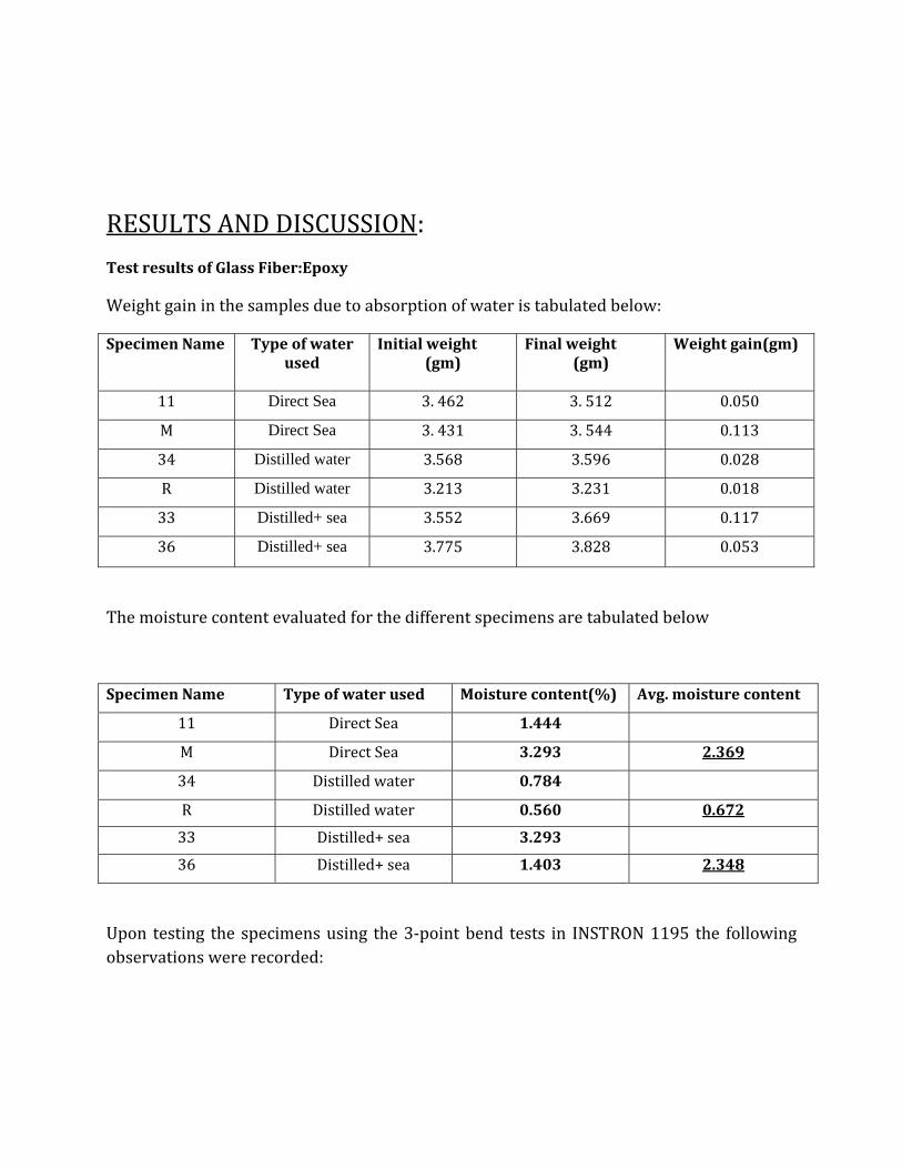
RESULT AND DISCUSSION: Test results of Glass Fiber:Epoxy
For cross head velocity=1mm/min
Specimen Name
Duration kept in liquid nitrogen(mins)
Width(mm) (b)
Thickness(mm) (d)
Load at yield(max load in kN) (Pb)
ILSS (0.75Pb/bd) (kN/mm2)
Avg. ILSS
(Mpa)
K 15 7.130 5.860 1.847 0.0331 33.10 I 30 6.100 7.190 6.779 0.1150 115.0 O 45 7.200 6.060 1.746 0.0300 30.00
The above tables gives us the values of ILSS for 2 different cross–head speeds 1 and 500mm/min.
Under Ambient conditions:
Specimen Name
Crosshead velocity (mm/min)
Width(mm) (b)
Thickness(mm) (d)
Load at yield(max load in kN)
(Pb)
ILSS (0.75Pb/bd) (kN/mm2)
Avg. ILSS
(Mpa)
B 1 7.150 6.090 1,537 0.0264 F 1 7.390 5.990 1.623 0.0274 26.90 D 500 7.630 5.960 1.623 0.0267 Q 500 7.390 6.080 1.606 0.0268 26.75
The ILSS values at cryogenic temperature and ambient temperature of untreated samples are plotted against the cross head speeds of 1 mm/min, and 500 mm/min for glass/epoxy laminates in the figure for different intervals of time. The plot shown below gives a comparision between the ILSS values obtained when the samples were dipped for a period of 15 mins in liquid nitrogen and the untreated samples at ambient temperatures.
0 100 200 300 400 50026.5
27.0
27.5
28.0
28.5
29.0
29.5
30.0
30.5
31.0
31.5
32.0
32.5
33.0
33.5
ILS
S(M
Pa)
Loading Rate(mm/min)
Liq N2(15mins) ambient
From the graph we note that the ILSS is maximum for cryogenically treated laminates than the untreated laminates for all the loading rates. This may be due to cryogenic hardening of the matrix phase at low temperature. The polymer chains get frozen due to which the deformation process is reduced results in less polymer relaxation i.e. it get hardened. We know that the fibres are much stronger than the matrix and since the overall composite is a solid system, the fibres tend to shrink more than the polymer matrix. This straining of the fibres requires space which ultimately leads to breakage of the composite as a whole. Residual stresses build up due to differential thermal contraction between fiber and matrix during sudden cooling from room temperature to cryogenic temperature as a result of which minute cracks occur at the polymer. When the load is applied, these stresses greater than the shear strength of the resin is readily generated and failure of the resin phase will result or fracture is induced when the stress induced stress intensity factor exceeds the fracture toughness of the resin. By controlling the molecular structure the performance of the resin can be optimized.
When the loading rate increases from 1 to 500mm/min the above mentioned cracks grow at a faster rate. So the possibility of crack closure reduces and eventually the failure stress drops down
0 100 200 300 400 50020
40
60
80
100
120
ILS
S(M
Pa)
Loading Rate(mm/min)
Liq N2 (30mins) ambient
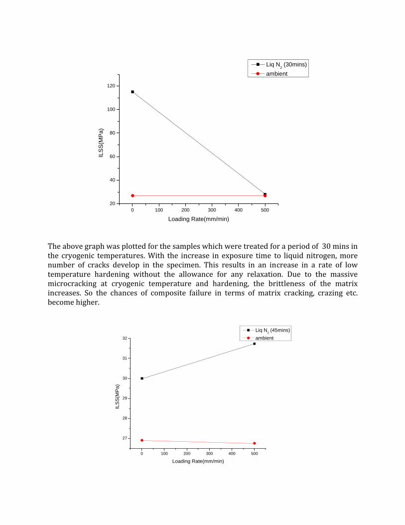
The above graph was plotted for the samples which were treated for a period of 30 mins in the cryogenic temperatures. With the increase in exposure time to liquid nitrogen, more number of cracks develop in the specimen. This results in an increase in a rate of low temperature hardening without the allowance for any relaxation. Due to the massive microcracking at cryogenic temperature and hardening, the brittleness of the matrix increases. So the chances of composite failure in terms of matrix cracking, crazing etc. become higher.
0 100 200 300 400 500
27
28
29
30
31
32
ILSS
(MPa
)
Loading Rate(mm/min)
Liq N2 (45mins) ambient
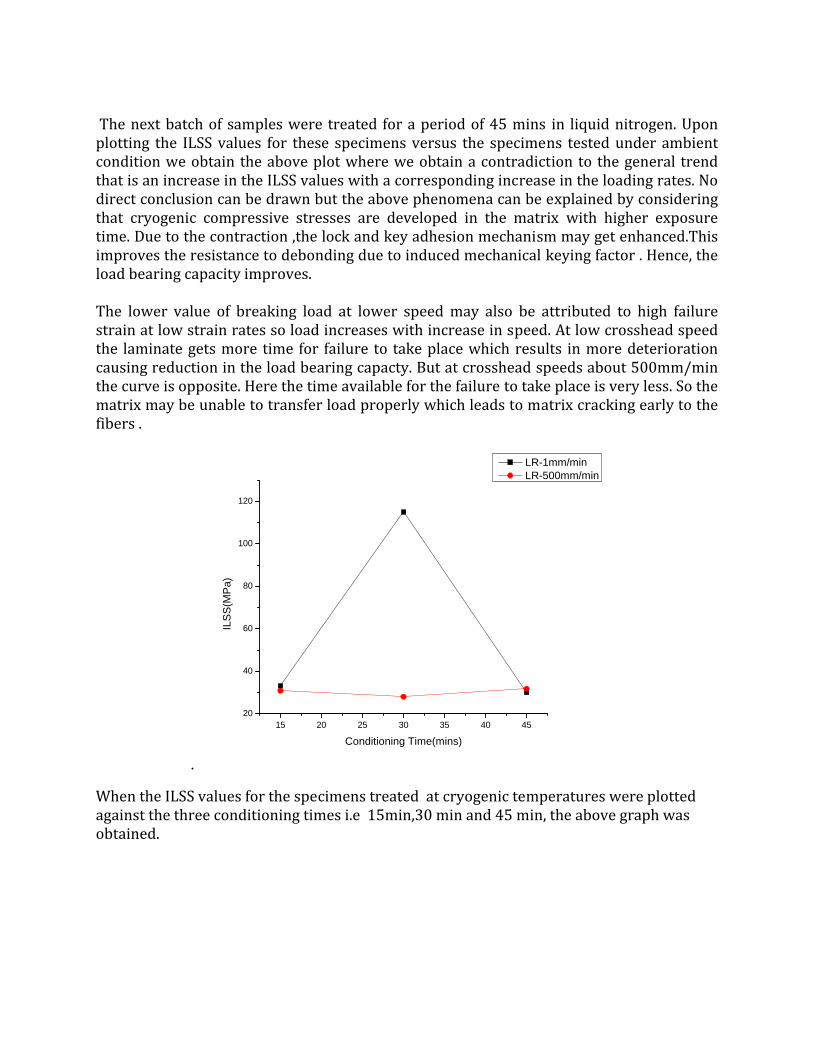
The next batch of samples were treated for a period of 45 mins in liquid nitrogen. Upon plotting the ILSS values for these specimens versus the specimens tested under ambient condition we obtain the above plot where we obtain a contradiction to the general trend that is an increase in the ILSS values with a corresponding increase in the loading rates. No direct conclusion can be drawn but the above phenomena can be explained by considering that cryogenic compressive stresses are developed in the matrix with higher exposure time. Due to the contraction ,the lock and key adhesion mechanism may get enhanced.This improves the resistance to debonding due to induced mechanical keying factor . Hence, the load bearing capacity improves. The lower value of breaking load at lower speed may also be attributed to high failure strain at low strain rates so load increases with increase in speed. At low crosshead speed the laminate gets more time for failure to take place which results in more deterioration causing reduction in the load bearing capacty. But at crosshead speeds about 500mm/min the curve is opposite. Here the time available for the failure to take place is very less. So the matrix may be unable to transfer load properly which leads to matrix cracking early to the fibers .
.
15 20 25 30 35 40 4520
40
60
80
100
120
ILS
S(M
Pa)
Conditioning Time(mins)
LR-1mm/min LR-500mm/min
When the ILSS values for the specimens treated at cryogenic temperatures were plotted against the three conditioning times i.e 15min,30 min and 45 min, the above graph was obtained.
The above SEM fractograph is obtained for a specimen treated in liquid nitrogen for a duration of 30 mins. It designates the prestate of cracking otherwise known as crazing where a complete separation of the two phases is not distinctly seen but it may lead to cracks upon increasing the loading rate which may ultimately lead to failure.
CONCLUSION: It is shown in the experiment that the breaking load values for the cryogenically conditioned laminates are higher than untreated laminates for all loading rates. This may be due to cryogenic hardening of the matrix and mechanical keying factor due to compressive residual stresses. This also results in lower strain values at maximum load for cryogenically conditioned laminates than the untreated laminates. Large debonded surfaces were found in cryogenically treated laminates.
It is also reasonable to conclude that the cryogenic hardening is evident mainly at lower range of crosshead speed. The effects result in higher ILSS values. Cryogenic compressive residual stresses are not nullified during thawing and results in higher ILSS value in compared to the non‐treated samples. The ILSS values start decreasing at higher loading rate for both the situations. It may possibly be attributed to the less prevalent relaxation process at the crack tip. The crack blunting may happen to be less common occurrence at higher rate of loading.
THERMAL AGING
INTRODUCTION : The interphase is defined as a region which is manifested as a result of bonding and reactions between the fiber and the matrix. This region is the site of synergy in composite materials and its influence to overall mechanical properties is significant[.36] It is generally recognized that the bond strength variation at the interface greatly affects the integrity of composite materials. The bond strength depends on quality of interfacial adhesion. It can vary in epoxy resin composites on the kind of aging conditioning[37]. Environmental attack can degrade fiber/matrix interface mostly by mechanochemical principle. Thermal aging behavior of epoxy resins is of special interest because of their expanding use for structural applications where increased temperatures are common environmental conditions. There are significant chemical and structural changes in epoxy networks take place during thermal ageing. Thermo‐oxidative degradation and disintegration of short‐range ordering are observed in epoxy network during thermal aging. It is concluded that these changes exert influence on the performance of epoxy matrix composites.[38,39].These alternations in bulk polymer matrix may affect the quality of adhesion at the interface Delamination and microcracking are some of the most frequently observed damage phenomena that may develop in polymer composites exposed to cryogenic temperatures[40]Research and development of polymeric materials for cryogenic applications have been intensified because of their specific usefulness in cryogenic environments. The physical properties of polymer materials depend decisively on frequencies of molecular excitation through the relaxation time that depends on temperature[41].It is important to understand the aging mechanism of polymer composites for their use in thermal environments. The mechanical behavior of composites depends on the ability of interface to transfer stress from the matrix to the reinforcement fiber. EXPERIMENTAL PROCEDURES: An unmodified epoxy resin based on Bisphenol‐A namely Araldite LY 556 and aliphatic primary amine hardener, HY951, were used with woven fabrics E‐glass fibers, treated with a silane‐based sizing system, to fabricate the laminated composites. They were cured for 24 hours at room temperature. The laminates of multi‐layered structures were cut by diamond cutter into short beam shear (SBS) test specimens. These ASTM standard (D2344‐84) specimens were used for interlaminar shear strength (ILSS) values. The fiber/matrix bond quality can be assessed from the gross mechanical properties such as ILSS and transverse tensile strength. The SBS test specimens were exposed to 75°C temperature oven for 5 hrs and 10 hrs respectively Another batch of samples was similarly exposed to ultra‐low deep freezer at −75°C temperature for 3 and 6 hours. One batch of specimens from thermal and cryogenic conditioning treatments at each point of conditioning time was tested in a three‐point flexural mode at ambient temperature to evaluate the ILSS values of the thermally as well as cryogenically aged samples.
Near about 8 samples were tested at each point of experiments and the average value was reported here. The ILSS value was calculated as follows,
ILSS = 0.75Pb/wt
Where Pb is the breaking load, w the width of specimen, and t the thickness of specimen. RESULTS AND DISCUSSION: Test results of Glass Fiber:Epoxy
Thermal Ageing (+750C)
For cross head velocity=1mm/min
Specimen Name
Duration kept in oven(hr)
Width(mm) (b)
Thickness(mm) (d)
Load at yield(max load in kN)
(Pb)
ILSS (0.75Pb/bd) (kN/mm2)
Avg. ILSS (Mpa)
E 5 7.260 5.880 1.494 0.0262 T 5 6.760 5.940 1.422 0.0266 26.40 X 10 7.080 6.020 1.566 0.0276 W 10 7.220 6.020 1.646 0.0284 28.00
For cross head velocity=500mm/min
Specimen Name
Duration kept in oven(hr)
Width(mm) (b)
Thickness(mm) (d)
Load at yield(max load in kN)
(Pb)
ILSS (0.75Pb/bd) (kN/mm2)
Avg. ILSS (Mpa)
Y 5 7.200 6.000 1.636 0.0284 C 5 6.200 5.900 1.329 0.0272 27.80 U 10 7.360 6.080 1.654 0.0277 B 10 7.100 6.080 1.629 0.0283 28.00
Under Ambient conditions:
Specimen Name
Crosshead velocity (mm/min)
Width(mm) (b)
Thickness(mm) (d)
Load at yield(max load in kN)
(Pb)
ILSS (0.75Pb/bd) (kN/mm2)
Avg. ILSS
(Mpa)
B 1 7.150 6.090 1,537 0.0264 F 1 7.390 5.990 1.623 0.0274 26.90 D 500 7.630 5.960 1.623 0.0267 Q 500 7.390 6.080 1.606 0.0268 26.75
the graph plotted above shows that at low crosshead speed i.e at 1mm/min the ILSS value for the specimens exposed to 75oC are lower as compared to the value at ambient temperature. But the case is just the reverse in case of 500mm/min where the ILSS value for thermally aged specimens is much higher. The reason behind the phenomenon lies in the fact that due to exposure to very high temperatures, at low crosshead speeds differential expansion occurs. But with an increase in the loading rate there an improvement in the adhesion mechanism between the fibres and the matrix and further cross linking is noticed in the matrix. At the same time the mutual migration between the epoxy and the fibre through the interface is enhanced drastically. Moreover, since the
0 100 200 300 400 50026.2
26.4
26.6
26.8
27.0
27.2
27.4
27.6
27.8
28.0
ILSS
(MPa
)
Loading rate(mm/min)
TA +750C(5hrs) ambient
surface is treated with silane, so interpenetration is quite effective. So, the overall adhesion chemistry of the composite increases. At such extremely high temperatures, there is every possibility of differential straining across the interface due to expansion. But the adhesion chemistry exercises a dominating effect resulting in an increase in the breaking load and thus the corresponding ILSS values are higher. The above graph shows the variation of ILSS with loading rate when the specimens are aged at 75oC for 10 hrs. Contrary to the aging at 5 hrs where there is a continual increase in the ILSS value with increase in loading rate, the graph for 10 hrs is simply a straight line. The straight line indicates that there is no significant difference in the values of ILSS at different loading rates. So to some extent the strength of the composite exposed to 75oC for 10 hrs is comparable to that at ambient temperature. This is because after a particular period of exposure the cross linking in the matrix is limited. After that there is no further improvement in the strength of the composite.
0 100 200 300 400 50024
25
26
27
28
29
30
31
32
ILS
S(M
Pa)
Loading Rate(mm/min)
TA +750C(10hrs) ambient
5 6 7 8 9 1026.2
26.4
26.6
26.8
27.0
27.2
27.4
27.6
27.8
28.0
28.2
ILSS
(MPa
)
Conditioning Time(hrs)
LR-1mm/min LR-500mm/min
The graph shows that the increase in ILSS value is drastic and fast for specimen loaded at a
rate 1 mm/min while it is moderate for 500 mm/min.
SEM Analysis for thermal ageing at +75oC
a) 5hrs b) 10hrs
As is evident from the fractograph the most common damage modes are matrix cracking, delamination growth and fiber fracture. Matrix cracking induces residual stresses of thermal origin and can be either micro‐ or macro‐residual stresses. The micro‐residual stresses arise from the differential coefficient of thermal expansion (CTE) of the fiber and matrix resin. This so‐called lamination residual stress promote the onset of cracking and delamination. SEM analysis for thermal ageing at 75oC
For 3hrs conditioning time Cryogenic exposure introduces matrix cracking as shown in SEM analysis and/or interfacial debonding. As fiber cross linking is highly probable during thermal conditioning as compare to during cryogenic conditioning the fiber/matrix adhesion is low in low temperature conditioning. So the first form of damage in laminates is commonly matrix microcracks and interlaminar cracks. These microcracks can also induce delamination. The immediate effect of such cracks is to degrade the thermomechanical properties of a laminated composite including Poisson ratios and thermal expansion coefficients
CONCLUSION: Thermal conditioning imparts better adhesion and thus an improved ILSS values. It is possibly attributed by surface chemistry principle at the fiber/polymer interface. Low temperature conditioning effect is not so significant in improving the adhesion quality and thus induces matrix microcracks and interlaminar cracks.Here strengthening phenomena may supposed be introduced by mechanical keying factor only at the fiber/matrix interfaces.
EFFECT OF ULTRAVIOLET IRRADIATION
INTRODUCTION : Polymer ‐matrix composites are widely used in a variety of applications, such as aerospace, mass transit, automotive, and sporting goods. However, their susceptibility to environmental degradation, especially ultraviolet (UV) irradiation, depending on the application and formulation of the matrix, has been of major concern. Solar UV radiation is deleterious to organic materials. The wavelength of the rays that reach the earth’s surface almost coincides with the dissociation energy of most polymers. On prolonged exposure of the composite to the sunrays, the matrix hardens and colour change and pigment loss can also occur. But they are constricted to the top few layers only.
The wavelength of UV components of solar radiation incident on the earth’s surface is under the 400 nm band. The energy provided by these UV photons falls within the range of the dissociation energies of polymer bonds, which are typically between 290 and 460 kJ/mole.[42] Thus, the chemical structure of the polymer is altered by photo‐oxidative reactions caused by the absorption of these UV photons. Most polymers absorb solar UV radiation, which causes photolytic, photo‐oxidative, and thermo‐oxidative reactions that can degrade the polymer. Polymer matrix composite materials are susceptible to this degradation by virtue of the matrix and its importance in determining properties. The degradation of the material can range from mere discoloration to a significant loss of mechanical properties. Most plastics or polymer products that are used in outdoor applications use photo‐stabilizers to prevent or minimize damage from UV exposure. The degradation mechanisms are quite complex and are usually dependent on the testing configuration and specific material being investigated.
Photo‐oxidative reactions cause molecular chain scission and/or chain crosslinking. Chain scission lowers the molecular weight of the polymer, while crosslinking causes brittleness, which can lead to micro‐cracking. The chain crosslinking caused by UV exposure can be advantageous and exploited, especially with thermoset resins, by using it as a curing agent. If the polymer absorbs visible wavelengths, the photo‐oxidative reactions can also cause the production of chromophoric chemical species, which may impart discoloration to the material.
Most plastics or polymer products that are used in outdoor applications use photo‐stabilizers to prevent or minimize damage from UV exposure. An autocatalytic degradation process is established if UV‐absorbing chromophores are produced. The formation of these groups provides a convenient means of monitoring the degradation process.
There has been substantial research conducted on UV exposure and the effects on fiber reinforced thermoset matrix composites. Some studies have also been conducted on discontinuous fiber reinforced thermoplastic composites. However, little, if any, work has been reported on continuous fiber reinforced thermoplastic composites exposed to moisture or UV. The synergistic effects of the UV exposure that are experienced by most composite materials can greatly affect the rate of degradation of the material.
EXPERIMENTAL PROCEDURE: The specimens were placed in RTR 200 UV exposure chamber with 12 fluorescent bulbs that provided UV irradiance at wavelengths of 200–400 nm within the chamber. These UV photons provide energy that is within the range of the dissociation energies of polymer bonds, which are typically between 290 and 460 kJ/mole. This typically results in chain scission. The specimens were removed at 100hrs of exposure and tested and evaluated.
RESULT AND DISCUSSION: The specimens that were exposed to UV started to show discoloration after 100 h of exposure, there was considerable yellowing of the specimens. There were no signs of chalking of the matrix or fibers that were exposed at the surface of the specimen. The specimens maintained their structural integrity and there were no visible signs of deterioration except for the yellowing. However SEM microscopy showed that the fiber–matrix interface was slightly detached but no cracks were evident on the surface of the specimens. The second micrograph shown below reveals some deformation undergone by the matrix due to UV exposure. The cracks thus developed in the matrix propagate throughout the matrix and lead to matrix failure and composite failure in turn at higher exposure durations.
CONCLUSION: Ultraviolet radiation is known to harden and discolor polymeric resin matrix. However, degradation takes place only at the skin of FRP laminates as the material has a screening effect although topcoat delamination may occur. For thicker composites degradation effects on mechanical properties is minimum. Use of UV resistant coating has been a popular tactic to substantially slow down or even eliminates the associated degradation. UV screeners such as carbon black and titanium dioxide are the oldest form of UV protection materials
for polymers. They have the ability to absorb light and increase photo stability. Light stabilizing oxidants such as hindered amine light stabilizers (HALS) are used to terminate the free radicals resulted from the bond breaking due to unreleased energy absorbed, hence retarding thermal oxidation. The combination use of UVA and HALS is observed to provide the greatest UV protection effect.
EFFECT OF MICROWAVE RADIATION
“This invention relates to heating systems for dielectric materials and the object of the invention is to heat such materials uniformly and substantially simultaneously throughout their mass. ... It has been proposed therefore to heat such materials simultaneously throughout their mass by means of the dielectric loss produced in them when they are subjected to a high voltage, high frequency field." The heating effect of microwaves was discovered accidentally in 1945. Percy Spencer, an American self‐taught engineer from Howland, Maine
INTRODUCTION: The curing of thermoset polymer adhesives such as epoxies has become increasingly important, arising from their application as matrix materials for aerospace and more recently as adhesives and encapsulating sealants for the microelectronics and electronics industries. In particular, the requirement for higher performing systems in terms of higher operational temperatures have also led to longer curing times for the systems used. Whilst thermal curing increases the cure rate and thus lowers the cure time, this is limited by the fact that the maximum rate of reaction for any given curing system already has an optimum temperature. Heating it to a temperature higher than this optimum would not increase its rate of reaction, but instead lead to thermal degradation of the material.
Microwave radiation, an alternative curing method which can accelerate the rate of reaction and hence the cure time, based on the resulting glasstransition temperature (Tg). Microwave curing has been found to be a viable alternative method for the curing of thermoset polymers, with a significant increase in the rate of reaction, obtaining a so‐called “rate enhancement”. Increasing demands on industrial applications in the microelectronics industries have led to the need for accelerated curing of high‐performance structural adhesive systems like epoxies. The curing of such thermoset systems has become the exibited a shorter curing time to reach the maximum percentage cure and Tg, the actual maximum values achieved for both percentage cure and Tg were significantly lower than for thermal curing. Recently, microwave curing has been shown to be a viable alternative as an accelerated curing system. bottleneck of the whole production process.
Tg is a an important physical parameter for polymeric materials for various reasons, the most important being that it becomes an upper‐bound limit for the service temperature of the material. This is simply because of the considerable drop in the bulk resin modulus once the material transforms from a glassy to a rubbery phase when it reaches Tg. For this reason, one of the main objectives in the curing of thermoset polymers is to increase the glass‐transition temperature to its maximum possible value. The rate enhancement resulting from microwave curing has been shown to be significantly higher than for thermal curing for epoxy systems with different curing agents.
Alternative curing methods to thermal curing to accelerate the curing process and thus reduce the time of cure, or to find a more energy‐efficient method for curing. These include the use of ultraviolet (UV) light, gamma rays and electron beams. UV light has limited application due to its poor penetration ability and limited dose rate. Gamma rays are usually delivered from naturally radiating sources such as cobalt‐60, which have enormous difficulties with regard to radiation hazard and environmental safety. Electron beam curing has proved to be an accelerated and efficient curing method, but often requires unacceptably high capital outlay. Microwaves have already been applied to many diverse industries. To the extent that microwaves do not have any of these inherent difficulties, the potential for industrial use is very high.
MICROWAVE OVEN:
Principle of working
A microwave oven works by passing non‐ionizing microwave radiation, usually at a frequency of 2.45 gigahertz (GHz)—a wavelength of 122 millimetres (4.80 in)—through the samples. Microwave radiation is between common radio and infrared frequencies. Many molecules (such as those of water) are electric dipoles, meaning that they have a positive charge at one end and a negative charge at the other, and therefore rotate as they try to align themselves with the alternating electric field of the microwaves. This molecular movement represents heat which is then dispersed as the rotating molecules hit other molecules and put them into motion. Microwaves penetrate dry non‐conductive substances at the surfaces of many common materials, and thus often induce initial heat more deeply than other methods. The depth of initial heat deposition may be several centimetres or more with microwave ovens. In contrast to broiling (infrared) or convection heating, microwaves penetrate dry non‐conductive substances at the surfaces , and thus often induce initial heat more deeply than other methods.. Penetration depth of microwaves is dependent composition and the frequency, with lower microwave frequencies (longer wavelengths) penetrating better. Moreover, large industrial or commercial microwave ovens operating at the common large industrial‐oven microwave heating frequency of 915 MHz—wavelength 328 millimetres (12.9 in)[43]
Design A microwave oven consists of:
• a high voltage power source, commonly a simple transformer or an electronic power converter, which passes energy to the magnetron
• a cavity magnetron, which converts high‐voltage electric energy to microwave radiation
• a magnetron control circuit (usually with a microcontroller) • a waveguide(to control the direction of the microwaves) • a cooking chamber
Most microwave ovens allow users to choose between several power levels. In most ovens, however, there is no change in the intensity of the microwave radiation; instead, the magnetron is turned on and off in duty cycles of several seconds at a time. Newer models have inverter power supplies which use pulse width modulation to provide effectively‐continuous heating at reduced power so that samples are heated more evenly at a given power level and can be heated more quickly without being damaged by uneven heating.
Heating characteristics:
In a microwave oven, samples may be heated for so short a time that it is processed unevenly, because heat requires time to diffuse through the samples, and microwaves only penetrate to a limited depth.
Uneven heating in microwaved sample can be partly due to the uneven distribution of microwave energy inside the oven, and partly due to the different rates of energy absorption in different parts of the food. The first problem is reduced by a stirrer, a type of fan that reflects microwave energy to different parts of the oven as it rotates, or by a turntable or carousel that turns the material; turntables, however, may still leave spots, such as the center of the oven, which receive uneven energy distribution. The location of dead spots and hot spots in a microwave can be mapped out by placing a damp piece of thermal paper in the oven. When the water saturated paper is subjected to the microwave radiation it becomes hot enough to cause the dye to be released which will provide a visual representation of the microwaves. If multiple layers of paper are constructed in the oven with a sufficient distance between them a three dimensional map can be created. Many store receipts are printed on thermal paper which allows this to be easily done at home. [43]
Microwave Radiation:
The radiation produced by a microwave oven is non‐ionizing. It therefore does not have the cancer risks associated with ionizing radiation such as X‐rays, ultraviolet light, and high‐energy particles. Long‐term rodent studies to assess cancer risk have so far failed to identify any carcinogenicity from 2.45 GHz microwave radiation even with chronic exposure levels, i.e., large fraction of one's life span, far larger than humans are likely to encounter from any leaking ovens.[43]
ADVANTAGE OF MICROWAVE RADIATION CURING OVER CONVENTIONAL THERMAL CURING:
1. Electromagnetic radiation processing, based on microwave curing has the advantage of significantly shorter total cure times compared to conventional thermal processing. Conventional processing is time consuming.
2. In Conventional curing matrix curing relies on thermal based techniques and is
dependent on heat conduction and convection. In contrast, electromagnetic
radiation in microwave processing penetrates the matrix surface and induces fast
curing through rapid dielectric‐related heat generation.
3. Greater consistency of cure has been reported for microwave processing.
4. High processing and equipment costs are involved in conventional curing processes.
But still the effect of microwave compared to thermal processing on both the matrix and composite properties is not clear. There is some discussion as to whether curing achieved through microwave processing is based solely on the heat generated (as in conventional thermal processing) or on both heat and other microwave induced molecular mechanisms. For this reason, differences in properties which can be attributed to processing technique have been investigated. Some experimental work on epoxy resins showed an increase in matrix modulus and a decrease in matrix tensile strength for microwaved compared to thermal cured specimens . In composite systems, the effect of processing technique on the interfacial strength is also dependent on factors such as the interaction of the fibre material with the microwave radiation and the thermal conductivity of the fibre. In addition, the possibility of forming a microwave‐induced interphase at the fibre‐matrix surface has to be considered. While it is known that the strength and toughness of composite systems are dependent on the interfacial properties, the influence of processing technique on interfacial properties has not been established. This is the focus of the present work. This paper examines the fundamental basis for the dependence of composite mechanical properties on the
processing technique by determining the influence of processing technique on the interfacial properties of a model glass fibre/epoxy composite. The interfacial properties including the interfacial shear (bond) strength , the shrinkage pressure on the fibre and the interfacial frictional shear stress . The effect of processing technique on the matrix moduli was also determined.
EXPERIMENTAL PROCEDURE: Three different sets of the samples consisting of 4 samples each were taken and placed in a microwave oven for three different intervals of time viz. 60mins, 90 mins and 120 secs. On the completion of microwave heating treatment the samples were wrapped in an aluminium foil in order to avoid the dissipation of heat entrapped in the laminates. These samples were then taken for 3‐point bend tests in INSTRON 1195 and were tested at two different speeds of 1mm/min and 500mm/min. SEM analysis was performed in order to understand the fracture mechanism and to evaluate the physical and mechanical properties of the laminates.
RESULTS AND DISCUSSION:
The above SEM fractographs are obtained when the specimens were subjected to microwave conditions in a microwave oven for a duration of 90 seconds.
In the first figure there is profound debonding across the matrix – fiber interface due to insufficient adhesion chemistry. The secondary bond attraction reduces. The second figure clearly shows the fiber pull out from the matrix due to which the matrix brittle failure dominates. Furthermore it is found that the extent of cross linking and the resulting microstructural integrity increases with an increase in the exposure time. In a nutshell, the
evaluated mechanical performance is a function of the conditioning time inside microwave oven.
CONCLUSION: The interfacial properties of composites can be determined from the single fibre pull‐out test. For the glass‐epoxy system considered, thermal processing leads to composites with higher strength compared to microwave processing. The difference in strength for composites processed using the two techniques is due to the higher pressure developed in thermal processing. Microwave processed composites would have lower configurations in which Pressure exerts a tensile stress on the interface would lead to lower interfacial bond strength. Further insight into the fundamental effects of microwave processing on epoxies is necessary before the influence of processing technique on thermoset‐based composites can be clearly understood . The test method adopted has a strong influence on the measured interfacial bond strength.
Hazards:
Liquids can superheat[43] when heated in a microwave oven in a container with a smooth surface. That is, the liquid reaches a temperature slightly above its normal boiling point without bubbles of vapour forming inside the liquid. The boiling process can start explosively when the liquid is disturbed, such as when the user takes hold of the container to remove it from the oven or while adding solid ingredients such as powdered creamer or sugar. This can result in spontaneous boiling (nucleation) which may be violent enough to eject the boiling liquid from the container and produce severe scalding. It is commonly, but wrongly, thought that only distilled water exhibits this behavior[43].
THERMAL SHOCK
THERMAL SHOCK ENVIRONMENT
Downthermal shock(+75oC to 75oC) and Upthermal shock(75oC to +75oC) treatments respectively on the composites laminates.
INTRODUCTION: A better fiber/matrix interfacial adhesion/bond will impart better properties such as interlaminar shear strength, delamination resistance, fatigue and corrosion resistance to a polymeric composite. This interfacial bonding is affected when exposed to thermal shock exposure of the composite. These aerospace materials frequently experience this kind of severe environmental exposure during their service life. [44] The most critical factor that greatly influences the mechanical behavior of composite materials is the fiber/matrix interfacial bond. The interfacial bond transfer loads and thereby ensures the integrity of composite materials. It is therefore necessary to examine what really happens at the interface by thermal shock treatment.[44] Thermal stresses were built‐up in glass fiber reinforced epoxy composites by up‐thermal shock cycles (negative to positive temperature exposure) for different durations and also by down‐thermal shock cycles (positive to negative temperature exposure). The concentration of thermal stresses often results in weaker fiber/matrix interface. Differential thermal expansion is a prime cause of thermal shock in composite materials. Thermal expansion differences between fiber and matrix can contribute to stresses at the interface.[45]. A very large thermal expansion mismatch may result in debonding at the fiber/matrix interface and/or a possible matrix cracking due to thermal stress. The fiber/matrix interface is likely to affect the overall mechanical behavior of fiber‐reinforced composites. The performance of fiber reinforced composite is often controlled by the adhesion chemistry at the fiber/matrix interface. [45]Thermal expansion coefficients of polymers are substantially greater compared to metals or ceramics. That is why failure of the bond between fiber and resin occurs under the influence of temperature gradient. The common reinforcement for polymer matrix is glass fiber. One of the disadvantages of glass fiber is poor adhesion to matrix resin. Differential thermal expansion in a composite is a prime cause of thermal shock. Thermal expansion coeffients in polymers are considerably greater, thus failure of the bond between fiber and resin may occur under extreme of temperature[46]. Thermal stresses caused by temperature gradient should be given special attention in many application areas. A better understanding of interfacial properties and characterization of interfacial adhesion strength can help in evaluating the mechanical behavior of fiber reinforced composite materials.
EXPERIMENTAL PROCEDURE: The specimens were treated in a thermal shock environment with a 150oC temperature gradient by two separate routes; for one batch of specimens it was from 75oC to ‐75oC and for the other batch it was in the reversed direction. The first batch of samples were exposed to the 75oC for 30 minutes after the oven had attained the 75oC temperature and then immediately were exposed to ‐80oC temperature for 30 minutes in Ultra Low Chamber. The three‐point bend tests of the conditioned specimens were carried out at room temperature almost instantaneously to avoid any reversible recovery and /or relaxation processes in the composites with an Instron tensile testing machine. The tests were performed at a crosshead speed of 1 mm/min and 500 mm/min for each stage of thermal conditioning temperature and time. Results from such tests are useful for the estimation of composite quality.
RESULT AND DISCUSSION:
The thermal conditioning at 75oC for the epoxy system results in further cross‐linking in the epoxy matrix and improves adhesion at the interface either by mechanical interlocking or by a surface chemistry mechanism. This all results in post‐curing strengthening. While cryogenic conditioning at ‐75oC may impart different degrees of shrinkage compressive strength at the interface. This could help in strengthening at the interface. The effect of thermal shock definitely causes debonding and /or weakening of the interface because of the different thermal coefficients of expansion and /or contraction for the polymeric matrix and the fibre reinforcement.
The combined effects of thermal shock on thermally conditioned specimens and also on cryogenically conditioned composites were investigated in each stage of the experiment. The improvement of shear strength is noticeable for the epoxy system. The strengthening effect may be the result of further cross‐linking in the epoxy matrix and it may impart further adhesion at the interface. Several mechanisms may contribute to the fiber/matrix adhesion, i.e. covalent bonding, physical interactions, and mechanical interactions. These post‐curing phenomena could dominate over de‐adhesion effect of thermal shock. Thus improvement in shear strength is reflected for the epoxy composite. But the weakening effect of thermal shock might dominate over the post‐curing hardening effect in the polyester system and thus consequently, it may result in the reduction of shear strength.
Downthermal shock conditions(+750C to750C):
0 100 200 300 400 50023.824.0
24.224.4
24.624.825.025.225.4
25.625.8
26.026.2
26.426.6
26.827.0
ILSS
(MPa
)
Loading Rate(mm/min)
Downthermal(+750C to -750C) ambient
The effect of downthermal cycle (from positive to negative temperature exposure) conditioning on ILSS values for 1 mm/min and 500 mm/min crosshead speeds.:
There are various sources of residual stresses during such type of complex and active environmental exposure. The thermal conditioning results in post‐curing strengthening effect. Residual stresses are also built up because of thermal expansion mismatch between the fiber and epoxy matrix. These misfit strains can result in debonding effects at the fiber/matrix interface. Another source of residual stress is the differential thermal contraction during sudden cooling from 75° C temperature to –75° C temperature. The cryogenic conditioning causes differential contraction and increases the resistance to debonding by better adhesion at the interface. The characteristic of the interfacial adhesion is strongly influenced by the presence of residual stresses. However, some of the stresses developed by differential expansion/contraction are relaxed by viscoelastic flow or creep in the polymer matrix. The rise in ILSS value may be attributed to the improved adhesion by cryogenic conditioning and also by the post‐curing strengthening phenomena.
Upthermal shock conditions(750C to+750C):
The variation of ILSS values of glass/epoxy laminates with the upthermal cycle (from negative to positive temperature variation) times at a crosshead speeds of 1 mm/min and 500 mm/min:
0 100 200 300 400 500
25.6
25.8
26.0
26.2
26.4
26.6
26.8
27.0
ILS
S(M
Pa)
Loading rate(mm/min)
upthermal (-750c to +750c) ambient
The continuous rise in ILSS is because of the quite large residual stresses due to the greater thermal expansion coefficient of the epoxy matrix. Higher thermal stresses might start dominating over the cryogenic compressive stresses for a longer thermal cycle time. The weakening effect of thermal shock is being nullified by the strengthening effect of post‐curing phenomena at 75°C temperature conditioning. The misfit strain may not be dominating over the further polymerization phenomena for conditioning at a 75°C temperature. The lower value of ILSS at lower crosshead speed may be due to higher failure strain of the epoxy matrix.
SEM ANALYSIS:
i) UP THERMAL (500mm/min) The micrograph shows the extensively damaged fibres in upthermal condition where breakage is due to brittle crack propagation. As we move to higher temperatures, the degree of cross linking increases . So the secondary bond attraction between fibers and matrix increases. Sliding is difficult.
ii) UP THERMAL (1mm/min)
The SEM micrograph given above shows the continuous and progressive deformation in the matrix under upthermal conditions . In general, the cracks that causes failure may nucleate from fibres, interface or the matrix. But in this case in particular, we get the damage through the matrix in a discrete manner i.e the cracks that were orginally initiated in the matrix propagates through the matrix folllowing a particular tren. Even the adhesion between the fibers and the matrix is not proper Each breakage in the matrix is prominently visible and is due to the fiber pull out creating flanges in the epoxy. So it becomes brittle. In the second micrograh, some damage along the fibres is noticeable.
iii) DOWN THERMAL(500mm/min) The above shown micrograph is obtained for specimen under down thermal condition where fiber breakage in a brittle manner is reflected prominently.When the temperature is suddenly lowered down to around ‐75oc, low temperature hardening takes place and the fibers become rigid.The mobility reduces and so no relaxation is possible. Due to this increase in rigidity, the fibres cannot slide against each other and break without prior deformation.
iv) DOWN THERMAL(1mm/min)
The micrograph reveals the fiber pull out in down thermal condition at lower cross head speed.
CONCLUSION:
The interactions between fiber and polymer matrix during thermal cycling are important phenomena. It may be reasonable to conclude that both modes of thermal cycling results in improvement of shear strength for the longer times duration. The debonding effect of thermal shock is evident for the lesser time.
Due to the large temperature gradient between +75oC to ‐75oC, numerous cracks are generated in the matrix. As a result residual stresses are generated that causes matrix failure at the same time poor adhesion between fiber and matrix and resulting inhomogeneity induces matrix and interfacial damage. At low cross head velocities the ILSS value is less sensitive as compare to high cross head velocities.
EFFECT OF SEA AND DISTILLED WATER
INTRODUCTION: The mechanical properties of thermoset resin‐matrix composite materials are affected when exposed to wet environments. The absorbed water causes matrix plasticization and/or interface degradation [47]. The effects of a water environment on moisture (H2O) absorption characteristics of a unidirectional epoxy composite material have been investigated by the measurement and analysis of weight change, hygrothermal induced expansion, surface crack formation, and surface mass loss.
Epoxy thermosets are a kind of polymers commonly used as adhesives, coatings and matrices in composite materials. They have good chemical, thermal, electrical and mechanical properties but, in many cases, they have the disadvantage of an important sensitivity to water absorption because of large amounts of polar OH groups in the networks which facilitate attractive interactions with polar molecules such as water. For instance, epoxy composites are very popular as encapsulants, for electronic components and as insulators in high voltage engineering and, when important water absorption takes place usually an overall degradation of the dielectric properties exists. Besides, among other effects, a small amount of water in epoxy resins may cause poorer mechanical properties (lower values of the modulus, brittleness) due to:
Plasticization decreasing the values of the glass transition temperature, Tg (it is reported a reduction of about 20 oC for every 1% of water absorbed)[47] ,
stress generation due to the swelling of the system [47] and a possible chemical degradation [47]
On the other hand, the presence of low levels of water within a polymer may enhance degradation of polymer‐reinforcement interfaces of composites which, in many cases, is the origin of the final failure of the material[48].
One important fact to take into account is the possible mismatch between the amount of moisture absorbed by the epoxy bulk and by the interphase. This phenomenon may induce volumetric expansion between the matrix and the fibres and, therefore may force the evolution of localized stress and strain fields in the composite [48]
In general, when ingress of water in epoxy systems takes place, two possibilities are assumed for then:
(i) the water is either strongly interacting with specific (polar) groups of the epoxy matrix or
(ii) clustered together in free volume microvoids as ‘‘free water’’ [48].
The water sorption behaviour is hence considered to depend on free volume properties and type and concentration of polar groups in the epoxy system. Due to this and, if there is a clear influence of the nature of the reinforcement surface for a glass fibre/epoxy composite on the structure of the epoxy along tens of microns from the glass fibre surface.[49]
Water absorption is an important parameter in the degradation of polymer composites applied in marine field. The gain of the water content enhances the probability of material degradation which generally follows three main mechanisms:
direct diffusion of water molecules through the matrix and, in some cases, through the fibres;
capillary flow of water molecules along the fibre/matrix interface followed by diffusion from the interface into the bulk resin. This is a consequence of debonding mechanisms between the fibres and matrix caused by water attack at the interface[49]
diffusion through micro‐cracks, pores, defects in the material.[49]
In the material response to the overall moisture absorption process, cracks (including surface voids) and the surface mass loss (including surface peeling and dissolution) has great influence on the apparent weight change behavior. Surface peeling and resin dissolution contribute to weight loss (a net decrease of the overall weight) of the specimen, whereas surface crack and voids between fibers trap water thus promoting weight increase.
The overall weight change profile encompasses the combined competing effects of water diffusion, physio‐adsorption of water at crack tips which promote weight gain in the laminate, and surface mass loss mechanisms which contribute to gross weight reduction. The cracking is due to the large difference in water‐induced swelling between the fiber and weight change profile encompasses the combined competing effects of water diffusion, physio‐adsorption of water at crack tips which promote weight gain in the laminate, and surface mass loss mechanisms which contribute to gross weight reduction. The cracking is due to the large difference in water‐induced swelling between the fiber and matrix phase. Owing to the difference in elasticity and moisture expansion coefficient, stress develops along the graphite fiber and matrix interface. In the interior of the specimen, the stress equilibrium is more easily maintained. However, at the exterior, edge stresses are of sufficient magnitude to produce cracking. When the stress exceeds the adhesive fiber/matrix bond strength, cracks may develop.
EXPERIMENTAL PROCEDURE: In our experiment the effect of immersion in distilled water, sea water and distilled and sea water in a 50‐50 vol% upon the interlaminar shear strength (ILSS) of a unidirectional epoxy composite is evaluated. Although the ILSS test has numerous known limitations, it was selected because it is a reproducible and non‐expensive method which qualitatively measures the fiber/matrix interface integrity.
On one hand sea water was heated in a container till bubbles started forming and the temperature was recorded around 95oC using electronic thermometer by dipping the wires of the measuring gauge into the water when bubbles had just started to form. This temperature is recorded as the experimental boiling point of sea water. Then the specimens(2 in nos.) were immersed in it and heating was continued upto 30minutes. Similarly 2 other specimens had undergone the same treatment under distilled water where the experimental boiling point was recorded as 80oC.
On the other hand , specimens (2 in no.) were immersed in a combination of distilled and sea water(50‐50 vol%) for 30 minutes. Once the specimens were taken out from the container, the surface water was absorbed by using dry cotton. They were weighed. Weight gain and water‐induced expansion were measured by measuring the moisture content . The relative mass change of the epoxy in the specimens under study expressed as a percentage was obtained using the expression:
Moisture content = Weight of soaked specimen ‐ Weight of dry specimen x l00 [%] Weight of dry specimen
. Three‐point bend test method and scanning electron microscope (SEM) were done in order to evaluate the mechanical and physical properties of the laminates and to investigate the surface modifications.
RESULTS AND DISCUSSION: Test results of Glass Fiber:Epoxy
Weight gain in the samples due to absorption of water is tabulated below:
Specimen Name Type of water used
Initial weight (gm)
Final weight (gm)
Weight gain(gm)
11 Direct Sea 3. 462 3. 512 0.050
M Direct Sea 3. 431 3. 544 0.113
34 Distilled water 3.568 3.596 0.028
R Distilled water 3.213 3.231 0.018
33 Distilled+ sea 3.552 3.669 0.117
36 Distilled+ sea 3.775 3.828 0.053
The moisture content evaluated for the different specimens are tabulated below
Specimen Name Type of water used Moisture content(%) Avg. moisture content
11 Direct Sea 1.444
M Direct Sea 3.293 2.369
34 Distilled water 0.784
R Distilled water 0.560 0.672
33 Distilled+ sea 3.293
36 Distilled+ sea 1.403 2.348
Upon testing the specimens using the 3‐point bend tests in INSTRON 1195 the following observations were recorded:
For cross head velocity=1mm/min
Specimen Name
Duration kept in beaker
containing water(hr)
Width(mm) (b)
Thickness(mm) (d)
Load at yield(max load in kN) (Pb)
ILSS (0.75Pb/bd) (kN/mm2)
Avg. ILSS (Mpa)
M 1 6.860 6.100 1.408 0.0250 25.00
R 1 7.560 5.940 1.362 0.0227 22.70
33 1 7.770 6.180 1.417 0.0221 22.10
Two mechanisms can be imagined as contributing towards the overall hygrothermal effects on the reinforced plastics. Firstly, at the macroscopic level, the expansion of the matrix due to absorption of water may cause tensile stresses in the fibres and compressive stresses in the matrix which is similar to differential thermal expansion. Secondly, at the molecular level, the diffusing molecules of water and sodium chloride may strain or rupture the intermolecular bond in the matrix and at the interface. In the unreinforced resin the microscopic damage is the only possible mechanism and in the reinforced plastics also this mechanism predominates because the fibres are much stiffer than the matrix. However, comparatively higher reduction in the compressive strength of the composite can be attributed to the hydroexpansion.
SEM ANALYSIS:
The above SEM fractographs reveals minute cracks in the matrix which are possibly due to the osmotic blistering and moisture penetration into the matrix.It is found that the damage due to penetration is more in sea water than in distilled water.
CHAPTER 4
FUTURE SCOPE
The work carried out by us has scope of further improvement in the following areas:
• We had mainly used E‐Glass fibres for all of our experiments and results and had tried to explain the fracture mechanism of the GFRP composite in order to evaluate the physical and mechanical properties. We can try other fibres namely carbon and aramid in order to explain the complete damage and degradation study of FRP composites.
• The polymer resin used by us was Epoxy resin. Other resins systems could also be tried out.
• Other techniques including the DSC imaging, AFM techniques etc. could be used to have a better understanding on the fracture mechanism of the FRP composies.
REFERENCES
[1] Carl Zweben, Composite Materials and Mechanical Design, Mechanical Engineer's Handbook, 2nd ed., Myer Kutz, Ed., John Wiley & Sons, Inc., New York, 1998.
[2] Reed R P, Fickett F R, Summers L T and Stieg M. Advances in Cryogenic Engineering Materials. Volume 40B.
[3] Kelly A, Zweben C. Comprehensive Composite Materials, Polymer Matrix Composites. Oxford, U.K: Elsevier Science Publication, 2000. [4] Aggarwal B D, Broutman L J. Analysis and performance of Fiber Composites. Canada: Wiley-Interscience, 1990.
[5] Donnet J B, Bansal R C. Carbon Fibers. New York: International Fiber Science and Technology, 1984. [6] Hull D, Clyne T W. An Introduction to Composite Materials. Cambridge, UK: Cambridge Univ. Press, 1996. [7] ANG B.Z. Advanced Polymer Composites: Principal and Applications. ASM International, Materials Park, OH, 1994. [8] KNOPS M., BOGLE C. Gradual failure in fibre/polymer laminates. COMPOSITES SCIENCE AND TECHNOLOGY (2005). [9] http://www.blurtit.com/q760268.html ,retrieved on 10/05/2010,
[10] Hancox NL. Thermal effects on polymer matrix composites: Part 1. Thermal cycling. Mater Des 1998;19(3):85–91.
[11] Papanicolaou GC, Anifantis NK, Keppas LK, Kosmidou ThV. Stress analysis of short fiber reinforced polymers incorporating a hybrid interphase region. Compos Interf 2007;14(2):131–52.
[12] Ray BC. Thermal shock and thermal fatigue on delamination of glass fiber reinforced polymeric composites. J Reinforc Plastics Compos 2005;24(1):111–6.
[13] Ray BC. Effects of changing environment and loading speed on mechanical behavior of FRP composites. J Reinforc Plastics Compos 2006;25(12):1227–40.
[15]Szyszkowski W, King J. Stress concentrations due to thermal loads in composite materials. Comput Struct 1995;56(2/3):345–55.
[16] Papanicolaou GC, Michalopoulou MV, Anifantis NK. Thermal stresses in fibrous composites incorporating hybrid interphase regions. Compos Sci Technol 2002;62(14):1881–94.
[17] Hiemstra DL, Sottos NR. Thermally induced interfacial microcracking in polymer matrix composites. J Compos Mater 1993;27(10):1030–50.
[18] Roy S, Weiqun Xu, Sneha Patel, Scott Case. Modeling of moisture diffusion in the presence of bi-axial damage in polymer matrix composite laminates. Int J Solids Struct 2001;38:7627 41.
[19] Oliveira BF, Creus GJ. An analytical–numerical framework for the study of ageing in fiber reinforced polymer composites. Compos Struct 2004;65:443–57.
[20] Boukhoulda BF, Adda-Bedia A, Madani K. The effect of fiber orientation angle in composite materials on moisture absorption and material degradation after hygrothermal ageing. Compos Struct 2006;74:406–18.
[21] Chung K, Seferis JC, Nam JD. Investigation of thermal degradation behavior of polymeric composites: prediction of thermal cycling effect from isothermal data. Compos Part A: Appl Sci Manufact 2000;31(9):945–57.
[22] Zuckowski R. Analysis of thermal fatigue process. J Mater Process Technol 2000;106:167–72.
[23] Mao H, Mahadevan S. Fatigue modelling of composite materials. Compos Struct 2002;58:405–10.
[24] Gu P, Asaro RJ. Distortion of polymer matrix composite panels under transverse thermal gradients. Compos Struct 2008;82:413–21.
[25] Saud Aldajah , Ghydaa Alawsi , Safaa Abdul Rahmaan Impact of sea and tap water exposure on the durability of GFRP laminates,,2008
[26] Yasuhide Shindo, Akihiro Inamoto, Fumio Narita, Katsumi Horiguchi Mode I fatigue delamination growth in GFRP woven laminates at low temperatures Engineering Fracture Mechanics, Volume 73, Issue 14, September 2006
[27] Yasuhide Shindo, Akihiro Inamoto, Fumio Narita Characterization of Mode I fatigue crack growth in GFRP woven laminates at low temperatures Acta Materialia, Volume 53, Issue 5, March 2005
[28] A.M.A. El-Habak Mechanical behaviour of woven glass fibre-reinforced composites under impact compression loadComposites, Volume 22, Issue 2, March 1991,
[29] H. M. Hsiao, I. M. Daniel Strain rate behavior of composite materials Composites Part B: Engineering, Volume 29, Issue 5, September 1998
[30] M. Gong, X.F. Wan Experimental study on mechanical behavior of laminates at low temperature Cryogenics, Volume 47, Issue 1, January 2007g, J.H. Zhao
[31] Vernon T. Bechel, John D. Camping, Ran Y. Kim Cryogenic/elevated temperature cycling induced leakage paths in PMCs Composites Part B: Engineering, Volume 36, Issue 2, March 2005
[32] Sandhya Rao, RMVGK Rao Cure studies on bifunctional epoxy matrices using a domestic microwave oven Polymer Testing, Volume 27, Issue 5, August 2008
[33] S. Birger, A. Moshonov, S. Kenig The effects of thermal and hygrothermal ageing on the failure mechanisms of graphite-fabric epoxy composites subjected to flexural loading Composites, Volume 20, Issue 4, July 1989
[34] Surendra Kumar M and B. C. Ray MECHANICAL BEHAVIOR OF FRP COMPOSITES AT LOW TEMPERATURE
[35] Yasuhide Shindo , Tomo Takeda , Fumio Narita , Nozomi Saito , Shinya Watanabe , Kazuaki Sanada Delamination growth mechanisms in woven glass fiber reinforced polymer composites under Mode II fatigue loading at cryogenic temperatures
[36.] Hodzic, A.; Kim, J.K.; Lowe, A.E.; Stachurski, Z.H. Compos Sci and Tech 2004, 64, 2185.
[37]. Plonka, R.; Mader, E.; Gao, S.L.; Bellmann, C.; Dutschk; V.; Zhandarov, S. Composites Part A 2004, 35, 1207.
[42]. Saud Aldajah Ammar Al-omari and Ashraf Biddah Accelerated weathering effects on the mechanical and surface properties of CFRP composites
[43]. http://en.wikipedia.org/wiki/Microwave_oven, retrieved on 10/05/2010
[44].B.C.Ray,Study of the influence of thermal shock on interfacial damagein thermosetting matrix aramid fiber composites.
[45]. B. C. Ray Thermal shock on interfacial adhesion of thermally conditioned glass fiber/epoxy composites [46]. B.C.Ray, Effects of Thermal and Cryogenic Conditionings on Mechanical Behavior of Thermally Shocked Glass Fiber/Epoxy Composites
[47]. Effects of distilled water and saline solution on the interlaminar shear strength of an aramid epoxy composite J.R.M. d’ALMElDA(Pontificia Universidade Catdlica do Rio de Janeiro, Brazil)Received 20 May 199 1; accepted in revised form 18 September 1991
[48]. Influence of water immersion on mechanical properties of quasi-isotropic glass fibre reinforced epoxy vinylester resin composites V.K. Srivastava Department of Mechanical Engineering, Institute of Technology, Banaras Hindu Uni6ersity, Varanasi 221005, India [49]. The effects of a water environment on anomalous absorption behavior in graphite/epoxy composites Jiming Zhou & James P. Lucas Department of Materials Science and Mechanics, Michigan State University, East Lansing, Michigan 48824, USA (Received 21 February 1994; revised version received 5 October 1994; accepted 22 November 1994)