Damage of Carbon/Epoxy Composite Plates Subjected toMechanical Impact and Simulated Lightning
Paolo Feraboli∗ and Hirohide Kawakami†
University of Washington, Seattle, Washington 98195-2400
DOI: 10.2514/1.46486
Damage is inflicted on carbon-fiber/epoxy composite plates using both simulated lightning strike and mechanical
impact in the effort to understand the relative effect of the two damage mechanisms. A methodology is proposed to
characterize the damage resistance and tolerance of unconfigured composite plates subjected to lightning strike in a
fashion that is consistent with the extensive work previously done on low-velocity impact. Using current and voltage
diagnostics, it is possible to extrapolate the amount of electromechanical energy absorbed by the plate during the
strike and compare it to that absorbed during amechanical impact. Damage resistance is characterized by means of
ultrasonic C-scans and microscopy, whereas residual strength is measured by means of compression after impact
testing. Results show that the energy dissipated in a specimen during the lightning strike is much greater than the
strain energy introduced by mechanical impact, and hence a comparison based on energy is not recommended.
However, based on the relative threat levels associated with the impact and the lightning strike events, the
comparison yields insightful observations on both damage state and residual performance. In general, for the
configurations tested, lightning strike damage seems to be less detrimental than the mechanical impact in terms of
both damage area and residual strength.
I. Introduction
A WIDE range of composite material forms are finding use intoday’s aerospace, automotive, and other transportation
industry segments. These materials are finally fulfilling the promiseof providing aircraft manufacturers with a cost-competitivealternative to aluminum alloys. The Boeing 787 Dreamliner, due tojoin the world’s active fleet by mid-2009, features more than 50%carbon fiber reinforced polymers (CFRP) by structural weight [1].Beside the direct benefits resulting from the greater specificmechanical properties, such as increased fuel efficiency and reducedpollutant and acoustic emissions, other indirect advantages of aCFRP-intensive airframe are reduced maintenance requirements andincreased passenger comfort because of the superior fatigue- andcorrosion-resistance characteristics of these materials. However, theintroduction of composites in the primary structure of modernaircraft presents special problems with regards to the lighting strikethreat. Although metallic structures, such as traditional aluminumairframes, are highly conductive, CFRP have amuch lower electricalconductivity. Although carbon fibers are good conductors, thepolymer matrix is an excellent dielectric and therefore reduces theoverall conductivity of the composite laminate.
Lightning strike is a threat to all structures, whether metallic orcomposites, and requires careful consideration from a certificationstandpoint. Lightning can induce damage on a structure by meltingor burning at lightning attachment points, resistive heating,magnetic force effects, acoustic shock, arcing and sparking at joints,and ignition of vapors in fuel tanks [2,3]. Of particular interest toCFRP or other conductive composites is damage resulting fromacoustic shock and resistive heating. When lightning strikes, a largeamount of energy is delivered very rapidly, causing the ionized
channel to expand with supersonic speed. If the shock waveencounters a hard surface, its kinetic energy is transformed into apressure rise, which causes fragmentation of the structure. On theother hand, resistive heating leads to temperatures rise, and in turn itinitiates a breakdown of the resin/fiber interface by pyrolysis. If thegases developing from the burning resins are trapped in a substrate,explosive release may occur with subsequent damage to thestructure.
Although extensive literature is available regarding the threat offoreign object impact damage to composites [4–6], limited work hasbeen published to assess the structural performance of CFRPspecimens following lightning strike damage [7,8]. In a previousstudy [8], the authors inflicted simulated lightning strike damage atthree different current levels (10, 30, and 50 kA) on carbon/epoxycoupons inorder to characterize their damage resistance and toleranceresponse. Both unnotched and filled-hole (using an aircraft-gradestainless steel Hi-Lok fastener) specimens were tested, all unpaintedand unprotected. After damage was inflicted, the CFRP specimenswere tested in tension and compression for residual strength. Theresidual tensile strength was in general mildly affected, both in theunnotched and filled-hole configurations, as well as the unnotchedcompressive strength. On the other hand, the filled-hole compressivestrength was dramatically reduced, particularly for 30 and 50 kAstrikes.Thecriticality of the compressive failuremodeover the tensileis not surprising for composites, but the negative influence of thefastener is not intuitive. Itwas found that for unnotched specimens thedamage tends tobeconfined to theouterplies inproximityof the strikelocation, whereas for filled-hole specimen, the damage tends tospread throughout the entire specimen thickness. The presence of thefastener has mixed effects: for low amperage strikes (10 kA), thefastener tends to absorb the majority of the damage; for higheramperages (30 and 50 kA), it acts as an amplifier by distributing thedamage throughout the entire thickness of the specimen. It wasobserved that at the higher current levels, particularly for the filled-hole specimens, the size of the damagewas too large for the small sizeof the specimens, which were rectangles of 12 � 1:5 in: (305�38 mm). As a result of this study, it was concluded that for futureresearcher it is recommended touse larger specimens, possibly squareplates of at least 6 � 6 in: (127 � 127 mm). Furthermore, given thecriticality of compression strength for filled-hole specimens, it wasrecommended to limit future research to this particular configuration.
The basic lightning protection regulation for airframes is the samefor all vehicle categories and appears in the Federal AviationAdministration (FAA)AdvisoryCircularAC25-21 [9] (Sec. 25.581),
∗Assistant Professor and Director, Automobili Lamborghini AdvancedComposite Structures Laboratory, Department of Aeronautics &Astronautics, Box 352400, Guggenheim Hall; [email protected](Corresponding Author).
†Graduate ResearchAssistant, Department ofAeronautics &Astronautics;Research Engineer, Japan Ministry of Defense, Tokyo.
which requires that the aircraft be able to sustain a lightning strikewithout experiencing catastrophic damage. These requirements areinherently nonspecific and allow manufacturers to adopt differentcertification strategies. However, SAE International providesaerospace recommended practices (ARP) that can be use to showcompliance with these requirements [10,11]. The accuracy of thetesting technique adopted as compared to real lightning strike eventsis fundamental question, and it has been discussed for decades.Previous work by NASA, FAA, and industry has led to thedevelopment of a recommended procedure: the SAEARP 5412 [11],which is accepted internationally as the sole test standard bywhich tosimulate lightning strike in a laboratory environment. The research
presented here follows accurately the recommendations containedin [11].
Although regulatory agencies impose compliance with safetyrequirements, aircraft manufacturers also have internal requirementsthat address both safety and economic concerns. In a fashion similarto foreign object impact damage [4], whereby detection thresholds[such asbarely visible impact damage] (BVID) andassociated impactenergy levels, are set to determine maintenance and inspectionprocedures, different threat scenarios exist for lightning strikedamage. Table 1 summarizes the levels of threat for both impact andlightning strike damage that are of interest to airframemanufacturers.The peak impact energy levels and lightning strike currents employedare lower than the peak values presented in Table 1 because they areadjusted to be adequate for the dimensions of the specimens beingconsidered. This study, although not focusing on the visualdetectability aspects of thedamage, aims at establishing a comparisonbetween the relative severity of mechanical impact damage andlightning strike damage. The worst conditions for evaluating theresidual strength in both types of damages are considered, whichinvolve compressive loads. Also, the lightning strike specimensinvolve filled-hole configurations, which have been shown to causegreater damage than unnotched configurations [8].
Table 1 Threat levels associated with lightning
strike and mechanical impact
Threat Lightning strike, kA Impact damage, ft � lb (J)
Very high 100–200 50–100 (67.8–135.6)High 50–100 30–50 (40.7–67.8)Medium 30–50 15–30 (20.3–40.7)Low 0–30 0–15 (0–20.3)
Fig. 1 Picture and schematics of the lightning strike generator.
1000 FERABOLI AND KAWAKAMI
II. Experimental Procedure
A. Description of the Lightning Strike Generator
The lightning strike generator developed at the University ofWashington is composed of a high-voltage capacitor, a high-voltageresistor, an adjustable resistor stack, a spark gap switch, the testspecimen, and the current return network, as shown in Fig. 1. Thecapacitor is capable of supplying 44 kVand 52 �F and the adjustableresistor stack is used to vary the amperage of the strike and tomodulate thewaveforms,while the spark gap switch is used to triggerthe strike. The area in proximity of the test specimen is reported in
more detail in Fig. 2 and shows the dielectric support frame, currentand voltage probes, the conical copper striker, theCFRP couponwiththe fastener, and the copper strips used to connect the specimen to theground. The CFRP specimen is supported at the two short endsbetween two copper electrodes, for which the position is adjusted tobe in close contact with the specimen and are encapsulated bynonconductive phenolic composites. Striker distance is kept constantfor all tests at 0.125 in. (3.2 mm). The generator is contained in achamber, which is electrically and physically separated from thesurrounding environment in order to ensure safe operation. Thelightning strike generator is capable of generating waveform D asspecified in SAE ARP 5412 [11]. Waveform D is designed torepresent a typical restrike after the primary strike to the airframe andis also used to certify the vast majority of the airframe acreage.Waveform D calls for a maximum of 100 kA, released over less than0:5 �s [8].
B. Lightning Strike Energy Calculations
According to the composite materials handbook-17 definition[12], damage resistance is a relationship between an external threat orevent and the resulting state of damage in the structure. On the otherhand, damage tolerance is defined as the relationship between theexisting state of damage in the structure, independently of how it wasintroduced, and its residual performance. Although interconnected,these two properties are very distinct. Traditional damage resistanceand tolerance studies [12,13] on composite materials investigate therelationship between themechanical damage inflicted on a specimen,such as low-velocity impact [14] or quasi-static indentation [15] andthe residual strength of the specimen [16]. These two relationshipsare often captured and summarized in two keyplots [12,13] that showthe relationship between projected damage area measured byultrasonic C-scan and impact energy, and the relationship betweenresidual strength asmeasured by compression after impact (CAI) andimpact energy. Often, the residual strength is normalized against thepristine (or undamaged) value of the compressive strength. Althoughquestions have been raised about the usefulness of theCAI test and itsapplicability to real configured structures for design and certificationpurposes, this systematic approach to impact damage character-ization is well known to the composites community and, with itslimitations, accepted by it. For lightning strike damage, a similarapproach has not been use in the open literature, partly because of theexperimental complexities associated with simulating lightningstrike, and partly because lightning strike has been traditionallyhandled as an electrical and ignition related problem more so than astructural integrity threat. This study proposes a unifyingmethodology that can evaluate the relative threat of lightning strikedamage to composite structures in a fashion similar to mechanicalimpact damage.
Energy is therefore the preferred metric by which mechanicalimpact threats are defined. For mechanical impact, the energy inputinto the specimen is dissipated in elastic deformation and vibrationand damage creation. The elastic portion is returned to therebounding impactor, whereas the remaining is dissipated and notreturned to the specimen. For the majority of impact events used toinflict damage, the authors have shown that the energy returned is asmall fraction of the total energy, although the bulk is dissipated inthe formation of damage [4,5].
An electromagnetic threat, such as a lightning strike, releases largeamounts of energy in the forms of thermal, electrical, and, to anextent, mechanical. However, for lightning strike, the severity of thethreat is classified by the intensity of the current. The current that isgenerated by the capacitor and used to strike the specimen is always
Fig. 2 Details of the test specimenarea of the lightning strike generator.
Table 2 Voltage: current intensity and energy dissipated for thethree threat levels of lightning strike used in this investigation
conserved. Although it is responsible for the creation of damage, itsmeasure does not give any indication with regards to the extent ofdamage. On the other hand, voltage is not conserved, and its dropacross the specimen can be used to calculate the energy dissipatedduring the event. To calculate the energy dissipated, it is necessary todevise a complex experimental setup that measures the voltage dropand the energy flow across the specimen during the strike. From theschematic of Fig. 1, it can be seen that the capacitor is charged by theuser to the desired voltage Vc, at which point the switch in the sparkgap is closed and the desired current Iin is introduced into thespecimen. To have an accuratemeasure of Iin rather than an estimatedvalue that may not account for the losses incurring between thecapacitor and the striker, a current probe is positioned right below thestriker. The air, which is a dielectric, breaks down and an electricalarc sparks between the striker and the fastener in the specimen. Onthe opposite side of the strike, a high-voltage probe is connected tothe fastener to measure the voltage Vgap, which together with Iindefines the entire electrical state of the specimen at the time of thestrike. The current then travels along the specimen toward the edgesclamped in the copper electrodes, thus dividing into Iout1 and Iout2,which are measured using other two current probes. The two copperelectrodes constitute the current return network. The ability tomeasure both of these return currents guarantees that the strike isbalanced and that there is no bias toward one of the copper electrodes.Additional high-voltage probes are also connected to the each of thecopper electrodes and measure the voltage drop across the specimenas defined byVout1 andVout2. Thus the current and voltage state of thespecimen after the strike is fully defined.
With these values, it is then possible to calculate the energydissipated during the strike. The definitions of electric power P is
P� I � V (1)
where I is the current and V the voltage, and integrating the powerover the duration of the event the energy generated is
E�ZP � dt (2)
The difference in potential between the fastener and one end of thespecimen is Vout1 � Vgap; thus, the energy consumed in one-half ofthe specimen is
E1 �Z�Iout1 � �Vout1 � Vgap�� � dt (3)
Similar considerations can be made for the other side. The totalenergy dissipated in the specimen is given by Ediss � E1 E2 andusing the relationship Iin � Iout1 Iout2, it is possible to write
To determine the energy dissipated in the lightning strike event, it istherefore necessary to measure three current values and three voltagevalues.
To verify that the calculations are accurate, it should be remindedthat the energy dissipated in the formation of the arc between thestriker and the fastener is
Earc �Z�Iin � Vgap� � dt (5)
and that the nominal energy generated by the capacitor is given by
Egen �1
2� C � V2 (6)
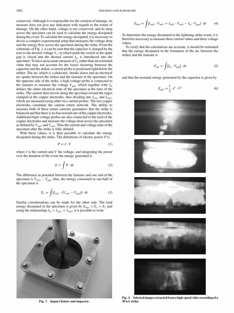
Fig. 4 Selected images extracted fromahigh-speed video recording of a
30 kA strike.Fig. 3 Impact fixture and impactor.
1002 FERABOLI AND KAWAKAMI
where C is the capacitance and Vc the voltage of the capacitor at thetime of the strike.
For the conservation of energy,
Egen � Ediss Earc Ereturn (7)
where Ereturn is the quantity remaining past the Vout1 and Vout2
measurements and that is either dissipated in the current returnnetwork or returned to the ground.
Table 2 shows the calculated energy dissipated into the specimenat the different current levels, corresponding to the threat levels ofTable 1. It can be seen that for the equivalent threat level, the energydissipated in a specimen subjected to mechanical impact is an orderof magnitude lower than the energy associated to a lightning strike.
C. Specimen Fabrication and Test Setup
Flat panels, having dimensions 13 � 13 in: (330 � 330 mm) ofTorayca T700S/2510 carbon-fiber/epoxy composites are fabricated
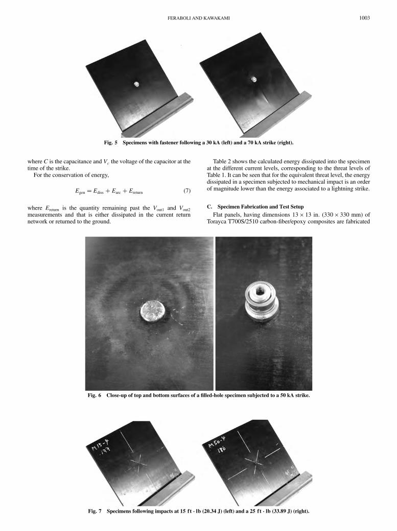
Fig. 6 Close-up of top and bottom surfaces of a filled-hole specimen subjected to a 50 kA strike.
Fig. 7 Specimens following impacts at 15 ft � lb (20.34 J) (left) and a 25 ft � lb (33.89 J) (right).
Fig. 5 Specimens with fastener following a 30 kA (left) and a 70 kA strike (right).
FERABOLI AND KAWAKAMI 1003
by pressmolding for 60min at 270F (132C) and 80 psi (0.55MPa).This system is designated for primary structures of general aviationaircraft and was characterized during the FAA-sponsored AdvancedGeneral Aviation Technology Experiment program in the late 1990sand early 2000s. The layup is �03= 452=04= � 452=04=902�S, or(65/24/11), for a total of 34 plies and a nominal thickness of 0.180 in.(4.6mm).Aftermolding, test coupons aremachinedwith a diamond-coated water-spray disk saw to the final dimensions of 6:0 � 6:0 in:(152 � 152 mm). The specimen dimensions for this study arepurposely selected to be large than the ones used in the previous studyby the authors [8] and allow for the lightning strike damage to be fullycontained within the boundaries of the specimen. The specimens arethen subjected to lightning strike or mechanical impact.
For the laminate stacking sequence considered in this study, aseries of coupon level tests are performed to measure the unnotched,open-hole, and filled-hole compressive strength of the laminate.Specimens of dimensions 12 � 1:5 in: (304:8 � 38:1 mm) are testedusing the Boeing-derived open-hole compression fixture of ASTMD6484 [17]. For the material and stacking sequence selected, it isfound that compressive strength is relatively insensitive to thepresence of a filled hole but very sensitive to an open hole. Detailedresults are reported in Table 3. These values are of little use for thedamage resistance and tolerance investigation performed in thisstudy and, by themselves, are not sufficient for a complete definitionof the laminate strength properties. However, they are generated toensure that the results that the CAI observations that follow forunnotched and filled-hole plates are consistent with the laminatecompressive strength properties.
For mechanical impact, the plates are clamped between the upperand lower portions of the indentation fixture specified in [15], whichhas a 5.0 in. (127 mm) diameter circular opening (see Fig. 3). Theplates are impacted with a falling weight of 10 lb (4.54 kg) fromdifferent heights to achieve the desired impact energy [4,5]. Formechanical impact, the maximum energy cutoff threshold for BVIDhas been traditionally considered 100 ft � lb (135.6 J). However, inthis study, energy levels of 5, 15, and 25 ft � lb (6.8, 20.3, and 33.9 J,respectively) are used. The upper energy threshold is highlydependent on the thickness of the material, and for the thicknessconsidered in this study, an energy value of 100 ft � lb (135.6 J) isexcessive. Already at 25 ft � lb (24.9 J), the projected damage areaapproaches the boundaries of the fixture, at which point the CAI
results cease to be meaningful. The impactor is a 1.0 in. (25.4 mm)diameter solid steel impactor.
For the lightning strike, the plates are first drilled to accommodatea 0.25 in. (6.35 mm) diameter aircraft-grade stainless steel Hi-Lokfastener. Only filled-hole plates are tested for lightning strike damagebased on the observations made by the authors in [8], andsummarized in the previous sections. From a practical perspective,because fasteners are always present on the skin of an aircraft, even acomposite-intensive one such as the Boeing 787 [1], lightning isknown to typically strike the metallic fastener rather than theunnotched skin. Therefore, evaluating the effect on filled-holespecimens has a dual significance of both representing the moststringent damage condition and the most realistic. Following theinstallation of the fastener, specimens are introduced in the test areaof the lightning apparatus and supported on two edges against thecopper electrodes. The panels are unpainted and unprotected:although not representative of a flight-ready composite airframe
Fig. 8 Ultrasonic C-scan of the postlightning strike specimens at 30, 50, and 70 kA.
Fig. 9 Ultrasonic C-scan of the postimpact specimens at 5 ft � lb (6.78 J), 15 ft � lb (20.34 J), and 25 ft � lb (33.89 J).
Fig. 10 Projected damage area for impact and lightning strike
specimens.
1004 FERABOLI AND KAWAKAMI
structure, this configuration allows for focusing on the details of theCFRP material response to high electrical discharges alone. For thisstudy, strikes at 30, 50, and 70 kA are used to inflict different states ofdamage to the coupons. All values are in line with the SAErecommended practice [11].
After introducing the impact or lightning strike damage, thespecimens are removed from their respective fixtures and trimmedalong the width to final dimensions of 6:0 � 4:0 in: (152�102 mm). They are subsequently clamped in the CAI fixture,according to ASTM International [17], and tested to failure torecord the residual strength. As discussed in preceding sections,compression loads are known to be most critical for the residualstrength assessment of CFRP panels following impact damage [12].The authors have shown that filled-hole compression is also themost critical load scenario for CFRP specimens following lightningstrike damage [8].
A total of 30 plate specimens are tested for residual strength,including unnotched pristine, unnotched postimpact, filled-holepristine, and filled-hole postlightning strike. Tables 4 and 5summarize the damage resistance and damage tolerance testsperformed in this study. Nondestructive inspection is performed on100% of the specimens via pulse-echo ultrasound using a C-scansystem with a 5 MHz sensor. The projected damage area is thenmeasured using image analysis software. Destructive inspection isperformed by cross sectioning and optical microscopy of thelightning-damaged specimens. Two micrographic coupons areextracted from a single test specimen in order to reconstruct thedamage state at the point of impact or strike in both the perpendicularand parallel to fibers direction. Mounting and sectioning lightningstrike composite specimens is best accomplished with a two-stagemount [8]. The strike area of the specimen is first vacuumimpregnated with the epoxy and then pressure cured to minimizeformation of air bubbles. The encapsulated area preserves the fragiledamaged material, as well as the fastener in place. Following the firstmounting, the specimen is then sectioned and mounted a secondtime: this time for the polishing operation. The specimen is polishedwith a six-step process: 180 grit, 600 grit, 1200 grit, 9 �m, 3 �msilk, 3 �m nonnap polyester, and ending upwith 1 h polishing with anonnap polyester cloth and 10% alumina solution [8]. Rhodamine Blaser dye is added to themounting epoxy, which gives it a red–orangetint. The use of a laser-dyed backfilled epoxy is very important todistinguish between the composite’s epoxy and the mounting epoxy.Without the dye, certain features can be subtle and contrast low, andthey may go undetected.
III. Results and Discussion
A. Damage Infliction
Lightning strikes produce a loud sound, similar to that of adetonation, and generate a short, bright light, followed by a cloud offire, smoke, and sparks because of the incandescent blast wavecharged with carbon fiber particles and vaporized epoxy. Figure 4 isextracted from a high-speed digital video recording of the striketaken at 83,000 frames per second and using a set of polarized filtersthat reduce the intensity of the light.
For filled-hole specimens, the results vary between the low- andhigh-current strikes. In the majority of the strikes, the only damagevisible is surface pitting of the fasteners on the head side, where the
strike takes place (see Figs. 5 and 6). For this material system andstacking sequence, even at 70 kA, only minor bulging of the pliestoward the surface is visible in the proximity of the fastener, andmodest fiber breakage is observable on both top and backfaces. Formechanical impact, all specimens show a small dent on the side of theimpactor, but even at the highest energy values, the dent does notbecome particularly deep nor leads to visible surface breakage (seeFig. 7).
Ultrasonic images for one representative filled-hole specimens ateach of the three strike levels are reported in Fig. 8. In the pristinespecimen, the fastener appears as a white round with an area ofapproximately 0:05 in:2 (32:2 mm2). For the 30 kA, strike thedamage area is contained in the fastener itself or in the immediateproximity of the fastener hole. For the 50 and 70 kA strikes, however,there appears to be a radical increase in damage area, and a largeportion of the specimen appears damaged. The projected damagearea is highly oriented along the direction of the zero axis, whichcorresponds to the direction along which the panel is clamped in thecopper electrodes.
For mechanical impact, ultrasonic images reveal that already at5 ft � lb (6.8 J), the state of internal damage is quite large, and at25 ft � lb (33.9 J), it has almost reached the boundaries of the testfixture (see Fig. 9). In general, the projected area of the impactdamage is more circular compared to the highly elliptical one of thelightning strike.
Table 4 Summary of damage infliction tests
Family Repetitions Damage type Threat Fastener diameter, in. (mm) Length, in. (mm) Width, in. (mm) Average damage area, in:2 (mm2)
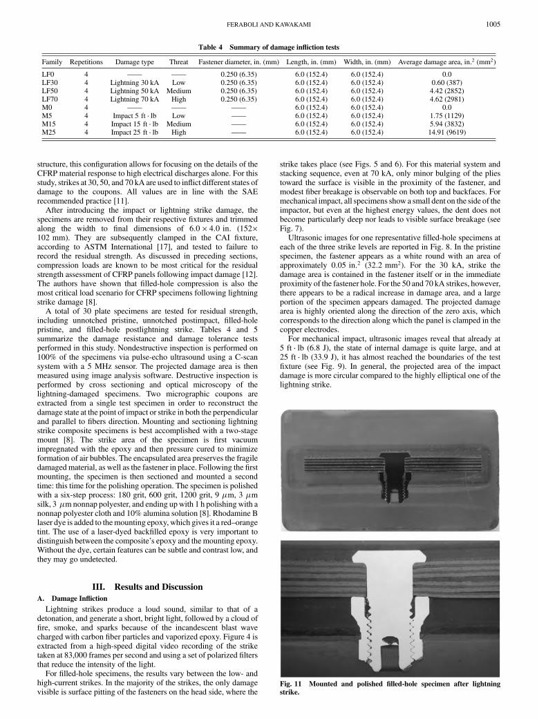
Fig. 11 Mounted and polished filled-hole specimen after lightning
strike.
FERABOLI AND KAWAKAMI 1005
Trends in projected damage area observed for filled-holespecimens subjected to lightning strike and for unnotchedspecimens subjected to impact damage are reported in Fig. 10. Theplot shows projected damage area against severity of threat level, asdescribed in Table 1. Results are summarized in Table 4. In general,the damage because of mechanical impact is much greater than theone caused by lightning strike, and the variation in measured data ismuch lower. The variability associated to lightning strike damage offilled-hole CFRP specimens is due to the relative fit of the fastenerin the plate. Although not easily quantifiable, the degree of fit of thefastener in the hole has a great effect on the resulting damage. If thegap between the fastener and the laminate is sufficiently large, theelectrical path is interrupted, and arcing between the fastener andthe neighboring plies occurs. This results in a larger damage area.For the lightning strike, it should be noted that between the 50 andthe 70 kA strikes, the damage area reaches an asymptotic value.This phenomenon is not easily explained because the variation inresults is so high, as discussed just previously. However, a possibleexplanation is that once the current reaches all plies along thethickness by passing through the fastener, the incremental amountof damage area is so widely distributed that the projected damagearea does not increase significantly. It should also be noted that asimilar phenomenon is expected to occur, for different reasons, formechanical impact specimens as well. For values of impact energyhigher than tested in this study, a plateau would be reached as thedamage area approaches the size of the circular aperture (i.e., theunsupported area).
B. Micrographic Inspection
For all specimens, microscopy is performed perpendicular as wellas parallel to the 0 deg fiber direction and at the midpoint of theimpact/strike location (see Fig. 11). For both damage types and for allthreat levels, specimens show extensivematrix damage in the form ofintraply cracks and interply delaminations. Fiber breakage is verymodest, if at all present. Detailed analysis of themicroscopic damageis beyond the scope of this study and will be the subject of a separatepublication. However, stereomicroscopy is used here to furtherassess the extent and location of the damage to complement theobservations performed by visual and ultrasonic inspections.
The mechanisms associated with the onset and propagation ofimpact damage in composite are not well understood. Hertziancontact and flexural deformations are responsible for the complexmulti-axial stress state at the point of impact and can, in part, justifythe formation of the well-documented delamination trees following
an impact event [12]. Yet, although years of research have beendedicated to characterizing impact damage on composites, it can besaid with a certain degree of confidence that the mechanisms bywhich a delamination originates at a given point, progresses for acertain length, and then changes plane in the form of a transversematrix crack are not clear. Furthermore, the influence of targetcharacteristics, such as stacking sequence, on impact damageresistance and tolerance has been assessed in several research studies,but it cannot be claimed that a thorough understanding of thecomplex interactions that exist between neighboring plies has yetbeen achieved.
The specimens obtained from the plate impacted at5 ft � lb (6.78 J)energy (see Fig. 12) show multiple 45 deg shear cracks emanatingdown into the laminate from the point of impact. These cracks runparallel to each other within a stack of plies of the same orientation,and then they propagate longitudinally along the next interface ofplies in the form of delaminations and eventually shear through the
Fig. 12 Micrographic images at 50 times magnification in the directions parallel and perpendicular to the 0 deg axis for a 5 ft � lb (6.78 J) impact
specimen.
Fig. 13 Detail of the specimen impacted at 5 ft � lb (6.78 J)
perpendicular to the 0 deg fibers and underneath the point of impact.
1006 FERABOLI AND KAWAKAMI
next stack of plies (see Fig. 13). This is the typical aspect of adelamination tree and is characterized by few thin and shortdelaminations for the majority of the polished specimen. The arearight underneath the impact point appears mostly pristine. Below themidplane of the laminate, there appears to be extensive crackingperpendicular to the plies, rather than at 45 deg, which suggest to betensile matrix cracks in the 90 deg direction. At 15 ft � lb (20.34 J),the overall aspect of the cross section is the same (see Fig. 14), but thedelaminations are larger and more diffused with complete separationof some of the ply stacks from the neighboring ones (see Fig. 15).There appears to be minor fiber breakage on the backface. For25 ft � lb (33.89 J), the amount of damage in the upper portion of thelaminate is very extensive with fiber breakage more diffused at thebackface (see Figs. 16 and 17).
For lightning strike damage, the situation is even more complex,given the electromagneto–thermomechanical nature of the threat,and the amount of research performed in the open literature to thisday is very limited. Lightning strike damage is a very complexphenomenon, which is possibly even more dependent on thecharacteristics of the target. Damage is thought to occur as a resultof the fact that the electrical conductivity of the plies is not sufficientto conduct the electrical current associated with the lightning strikeevent. The resistive heating that results is sufficient to pyrolize theresin and generates cracks and burns in the matrix. Simultaneously,
at the interface between neighboring plies, the mismatch inelectrical conductivity can lead to mechanical separation in the formof delaminations. The electrical properties of composite materialshave not been thoroughly studied as the mechanical ones. Theliterature to date does not offer suggestions in the electricalproperties of multidirectional laminates, neither in the elasticregion, which corresponds to the electrical response to currents thatdo not result in permanent damage, nor in the postelastic region,which corresponds to currents that result in the formation ofdamage. Nonetheless, stacking sequence is potentially even moreinfluential for this type of threat than for mechanical impact, so theresults obtained here pertain specifically to the laminate layupconsidered. Future research should be aimed at characterizing thedamage mechanisms associated with electrical currents for basicunidirectional plies, as well as multidirectional laminates, and it isanticipated that it will result in a better understanding of thecomplex lightning strike phenomenon. This section is limited todescribing and comparing the observations made on these specificspecimens, which have been damaged by means on mechanicalimpact and lightning strike.
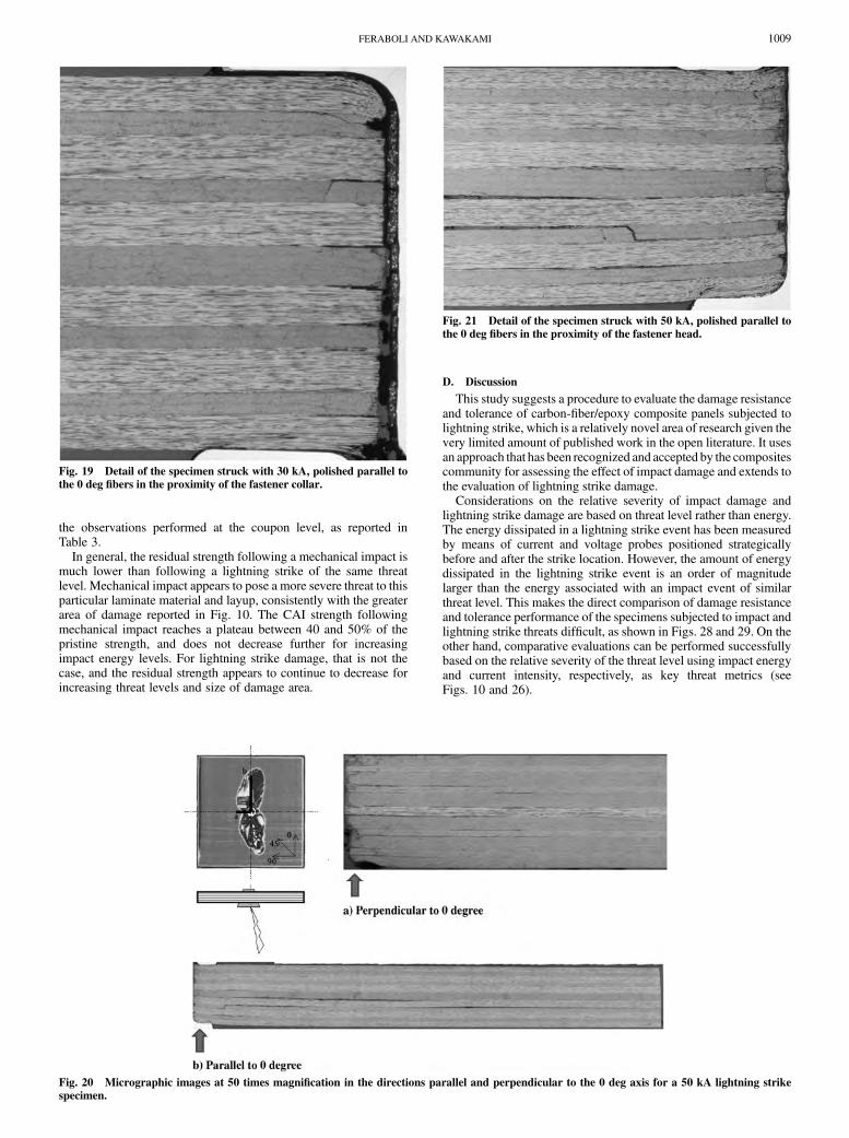
For specimens subjected to the 30 kA strike (see Fig. 18), damageis dispersed throughout the thickness of the laminate but is confinedto a small region in the proximity of the fastener. This damageappears in the form of matrix cracks within the plies anddelaminations at the ply interfaces. These cracks emanate from thefastener hole and propagate both downward and upward in thelaminate, usually parallel or at a small angle from the longitudinal(see Fig. 19). The plies that appear most damaged are the offaxisplies, in particular the 45 deg stacks and the interfaces between the 45and the 0 deg stacks. For 50 kA strikes, entire portions of the 45 and90 deg stacks are separated, both in the through-the-thicknessdirection and longitudinally (see Fig. 20). Damage is very extensive,particularly in the section polished parallel to the fibers, which alsocorresponds to the portion of the C-scan with the highly elongateddamage area. Long delaminations are visible in the laminate,particularly at the interface between zero-ply stacks and either �45or 90 deg ply stacks. The 0 deg plies on the upper and lower surfaceare also highly damage right under the fastener head and collar withcomplete separation and vaporization of small chunks of material(see Fig. 21). At 70 kA, the 90 deg stack at the midplane in the regionaround the fastener is composed of a dense network of cracks andsplits, which eventually lead to the formation of long delaminationfronts (see Figs. 22 and 23). Partial fragmentation of the 0 deg plystacks suggests that the fastener has the effect of distributing theelectrical load to all the plies in its contact or proximity.
Fig. 14 Micrographic images at 50 time magnification in the directions parallel and perpendicular to the 0 deg axis for a 15 ft � lb (20.34 J) impact
specimen.
Fig. 15 Detail of the specimen impacted at 15 ft � lb (20.34 J)
perpendicular to the 0 deg fibers and underneath the point of impact.
FERABOLI AND KAWAKAMI 1007
C. Residual Strength
After inflicting damage onto the specimens, these are tested tofailure using the Boeing-derived CAI fixture [17] to quantify the lossin mechanical performance because of the presence of damage (see
Fig. 24). For both pristine and filled-hole specimens, strength iscalculated based on the gross section area, consistently withaerospace practice [12]. All specimens reported failed in the netsection by an acceptable accepted compression failure mode asindicated by ASTM [17] (see Fig. 25).
Results for residual strength are reported in Table 5 and plotted inFig. 26 against the severity of the threat and, in Fig. 27, against theprojected damage area. This plot uses normalized strength values,which are obtained as the ratio of the damaged strength over thepristine or control strength. For impact damaged specimens, thenormalized strength is calculated as
�NORM ��UND�UN0
(8)
where�UN0 is the pristineCAI strength of the unnotched plate and�UNDis the damaged CAI strength of the unnotched plate. For lightningstrike damage, the normalized strength is calculated as
�NORM ��FHD�FH0
(9)
where �FH0 is the pristine CAI strength of the filled-hole plate and�FHD is the damaged CAI strength of the filled-hole plate. For thismaterial system and layup, the unnotched and filled-hole pristineCAI strengths are virtually identical (see Table 5), consistently with
Fig. 16 Micrographic images at 50 times magnification in the directions parallel and perpendicular to the 0 deg axis for a 25 ft � lb (33.89 J) impact
specimen.
Fig. 17 Detail of the specimen impacted at 25 ft � lb (33.89 J)
perpendicular to the 0 deg fibers and underneath the point of impact.
Fig. 18 Micrographic images at 50 times magnification in the directions parallel and perpendicular to the 0 deg axis for a 30 kA lightning strike
specimen.
1008 FERABOLI AND KAWAKAMI
the observations performed at the coupon level, as reported inTable 3.
In general, the residual strength following a mechanical impact ismuch lower than following a lightning strike of the same threatlevel. Mechanical impact appears to pose a more severe threat to thisparticular laminate material and layup, consistently with the greaterarea of damage reported in Fig. 10. The CAI strength followingmechanical impact reaches a plateau between 40 and 50% of thepristine strength, and does not decrease further for increasingimpact energy levels. For lightning strike damage, that is not thecase, and the residual strength appears to continue to decrease forincreasing threat levels and size of damage area.
D. Discussion
This study suggests a procedure to evaluate the damage resistanceand tolerance of carbon-fiber/epoxy composite panels subjected tolightning strike, which is a relatively novel area of research given thevery limited amount of published work in the open literature. It usesan approach that has been recognized and accepted by the compositescommunity for assessing the effect of impact damage and extends tothe evaluation of lightning strike damage.
Considerations on the relative severity of impact damage andlightning strike damage are based on threat level rather than energy.The energy dissipated in a lightning strike event has been measuredby means of current and voltage probes positioned strategicallybefore and after the strike location. However, the amount of energydissipated in the lightning strike event is an order of magnitudelarger than the energy associated with an impact event of similarthreat level. This makes the direct comparison of damage resistanceand tolerance performance of the specimens subjected to impact andlightning strike threats difficult, as shown in Figs. 28 and 29. On theother hand, comparative evaluations can be performed successfullybased on the relative severity of the threat level using impact energyand current intensity, respectively, as key threat metrics (seeFigs. 10 and 26).
Fig. 19 Detail of the specimen struck with 30 kA, polished parallel to
the 0 deg fibers in the proximity of the fastener collar.
Fig. 20 Micrographic images at 50 times magnification in the directions parallel and perpendicular to the 0 deg axis for a 50 kA lightning strike
specimen.
Fig. 21 Detail of the specimen struck with 50 kA, polished parallel to
the 0 deg fibers in the proximity of the fastener head.
FERABOLI AND KAWAKAMI 1009
This study selected a specific composite target configuration tovalidate the use of this approach. From the results shown, it appearsthat impact damage is a greater threat to carbon/epoxy compositeplates than lightning strike. However, it is important to remind thereader of the limited applicability of some of these results. First andforemost, these results apply only to the given prepreg tape materialand hence cannot be extended to other material types. In particular,material properties, such as fiber architecture (fabric vs tape) andthrough-thickness conductivity (influenced by resin-rich inter-laminar layers), are thought to be responsible for very differentdamage behavior under lightning strike and can lead to much greaterdamage states. Second, these observations are drawn on specimensthat are unpainted. The presence of a relatively thick paint layer on aflight structure has negligible influence on its impact damageperformance but is thought to be highly detrimental for lightningstrike damage [2,3] because the paint is a good dielectric. Third, thespecimens tested are all unprotected, which means they do not useany sort of lightning strike protection (e.g., a metallic wire mesh).This type of protection is known to be very effective in reducing theextent of lightning strike damage [2,3]. Fourth, the specimens testedfor lightning strike damage are all filled hole. The presence of thesteel fastener leads to more extensive damage than what is observed
Fig. 22 Micrographic images at 50 times magnification in the directions parallel and perpendicular to the 0 deg axis for a 70 kA lightning strike
specimen.
Fig. 23 Detail of the specimen struck with 70 kA, polished
perpendicular to the 0 deg fibers in the proximity of the fastener head.
Fig. 24 CAI test fixture with filled-hole specimen following lightning
strike damage.
Fig. 25 70 kA lightning strike specimen (left) and 25 ft � lb (33.89 J)
impact specimen (right) following residual strength CAI testing.
1010 FERABOLI AND KAWAKAMI
in identical but unnotched specimens [8] and diffuses it throughoutthe laminate thickness, thus making it the worst-case scenario. Fifth,these results are drawn on a specific laminate stacking sequence.Although stacking sequence has a large influence on the mechanicalimpact response of a plate, it has an even greater role on its lightningstrike damage response. The relative orientation of the 0 deg fiberswith respect to the current electrodes, as well as the orientation of theouter plies, can highly affect the overall state of damage in thelaminate. If the same layup were to be tested in the lightning strike
setup rotated by 90 deg, with the outer plies parallel to the copperelectrodes rather than perpendicular, different results would beobtained. On the other hand, for impact damage, there would be nodifference because both impactor and support fixture areaxisymmetric. Evaluation of the influence of these parameters isbeyond the scope of this study and shall be left for future researchactivities. Nonetheless, this paper defines a procedure that could beused successfully in those studies to assess the relative performanceof carbon/epoxy specimens under impact and lightning strike threats.
Table 5 Summary of residual strength tests
Family Repetitions Threat Residual strength test Length, in. (mm) Width, in. (mm) Average residual strength, ksi
LF0 3 —— CAI 6.0 (152.4) 4.0 (101.6) 65.8 (454)LF30 3 Low CAI 6.0 (152.4) 4.0 (101.6) 62.7 (432)LF50 3 Medium CAI 6.0 (152.4) 4.0 (101.6) 58.0 (400)LF70 3 High CAI 6.0 (152.4) 4.0 (101.6) 44.5 (307)M0 3 —— CAI 6.0 (152.4) 4.0 (101.6) 63.8 (440)M5 3 Low CAI 6.0 (152.4) 4.0 (101.6) 45.9 (316)M15 3 Medium CAI 6.0 (152.4) 4.0 (101.6) 28.3 (195)M25 3 High CAI 6.0 (152.4) 4.0 (101.6) 27.8 (192)
Fig. 26 Normalized CAI strength as a function of threat level for
impact and lightning strike specimens.
Fig. 27 Normalized CAI strength as a function of projected damage
area for impact and lightning strike specimens.
Fig. 28 Damage area for mechanical impact and lightning strike as a
function of input energy.
Fig. 29 Normalized CAI strength as a function of input energy for
impact and lightning strike specimens.
FERABOLI AND KAWAKAMI 1011
IV. Conclusions
The study compares the relative severity of lightning strike damageand mechanical impact damage on the residual strength of carbon/epoxy flat plates. Using standardized test methods, unnotched platesare subjected to dropweight impact and fastenerfilled-hole plates aresubjected to simulated lightning strike. Three different levels ofdamage are inflicted per test configuration, ranging from low-to-highthreat levels. The resulting state of damage is measured non-destructivelyviaultrasonicC-scananddestructivelyviamicrographicinspection. Results show that mechanical impact produces greaterdamage area than lightning strike. In both cases, damage is composedofamixofextensivedelaminationsandmatrixcracksandmodestfiberbreakage. After damage is inflicted, the plates are tested for CAIresidual strength: results show that the strengthdegradation followingmechanical impact is higher than lightning strike and the variationamong specimens tested is smaller. Though a complex experimentalsetup, the energy dissipated in the lightning strike event is measuredandcompared to theenergydissipated in themechanical impactevent.Results show that the energy dissipated in a specimen during thelightning strike is much greater than the strain energy introduced bymechanical impact, and hence a comparison based on energy is notrecommended.However, basedon the relative threat levels associatedwith the impact and the lightning strike events, the comparison yieldsinsightful observations on both damage resistance and tolerancebehavior of the composite plates.
Acknowledgments
The authors would like to acknowledge the fundamentalcontributions of their colleagues Art Blair, Robert Gordon, and TomMattick and undergraduate research assistants BenRenneberg,AndyLe, and Amy Nibert. They would also like to thank Robert Steinle,Diane Heidlebaugh, and Art Day (The Boeing Company) for theirtechnical support and expert advice. The material for this study wassupplied by Leslie Cooke of Toray Composites of America.
References
[1] Miller, A., “State of the Art Applications of Composites: The 787Dreamliner,” 22nd Annual Technical Conference of the American
Society for Composites, DEStech Publications, Inc., Lancaster, PA,Sept. 2007.
[2] Rupke, E., “Lightning Direct Effects Handbook,” LightningTechnologies, Inc., Rept. AGATE-WP3.1-031027-043, Pittsfield,MA, 1 March 2002.
[3] Fisher, F. A., and Plumer, J. A., “Aircraft Lightning ProtectionHandbook,” Lightning Technologies, Inc., Rept. FAA/CT-89/22,
Sept. 1989.[4] Feraboli, P., “Some Recommendations for the Characterization of the
Impact Performance of Composite Panels by Means of Drop TowerImpact Testing,” Journal of Aircraft, Vol. 43, No. 6, 2006, pp. 1710–1718.doi:10.2514/1.19251
[5] Feraboli, P., and Kedward, K. T., “Enhanced Evaluation of the LowVelocity Impact Response of Composite Plates,”AIAA Journal, Vol. 42,No. 10, 2004, pp. 2143–2152.doi:10.2514/1.4534
[6] Kan, H. P., “Enhanced Reliability Prediction Methodology for ImpactDamaged Composite Structures,” U.S. Dept. of Transportation,Rept. DOT/FAA/AR-97/79, Oct. 1998.
[7] Heidlebaugh, D., Avery, W., and Uhrich, S., “Effect of LightningCurrents on Structural Performance of Composite Materials,”International Conference on Lightning and Static Electricity, SAEInternational Paper 2001-01-2885, Seattle, WA, Sept. 2001.
[8] Feraboli, P., and Miller, M., “Damage Resistance and Tolerance ofCarbon/Epoxy Composite Coupons Subjected to Simulated LightningStrike,” Composites, Part A: Applied Science and Manufacturing,Vol. 40, Nos. 6–7, 2009, pp. 954–967.
[9] “Certification of Transport Airplane Structure,” U.S. Dept. ofTransportation and Federal Aviation Administration, AdvisoryCircular AC 25-21, Sept. 1999, pp. 657.
[13] Mitrovic, M., Hahn, H. T., Carman, G. P., and Shyprykevich, P., “TheEffect of Loading Parameters on Fatigue of Composite Laminates,”Composites Science and Technology, Vol. 59, No. 14, 1999, pp. 2059–2078.doi:10.1016/S0266-3538(99)00061-5
[14] “Standard Test Method for Measuring the Damage Resistance of aFiber-Reinforced Polymer Matrix Composite to a Drop-Weight ImpactEvent,” Book of Standards, Vol. 15.03, ASTM International,Std. ASTM D7136, West Conshohocken, PA, 2009.
[15] “Standard Test Method for Measuring the Damage Resistance of aFiber-Reinforced Polymer-Matrix Composite to a Concentrated Quasi-Static Indentation Force,” Book of Standards, Vol. 15.03, ASTMInternational, Std. ASTM D6264, West Conshohocken, PA, 2009.
[16] “Standard Test Method for Compressive Residual Strength Propertiesof Damaged Polymer Matrix Composite Plates,” Book of Standards,Vol. 15.03, ASTM International, Std. ASTM D7137, WestConshohocken, PA, 2009.
[17] “Standard Test Method for Open-Hole Compressive Strength ofPolymerMatrix Composite Laminates,”Book of Standards, Vol. 15.03,ASTM International, Std. ASTM D6484, West Conshohocken, PA,2008.


![Performance and failure of metal sandwich plates subjected ... · Keywords: sandwich plates, honeycomb core, folded plate core, strength, ductility, ... [Liang et al. 2007], two types](https://static.documents.pub/doc/80x56/5b14a9907f8b9a487c8e2ec3/performance-and-failure-of-metal-sandwich-plates-subjected-keywords-sandwich.jpg)


