5158 IEEE TRANSACTIONS ON MAGNETICS, VOL. 49, NO. 9, SEPTEMBER 2013
Damper Winding Influence on Unbalanced Magnetic Pull inSalient Pole Generators With Rotor Eccentricity
Mattias Wallin, Johan Bladh, and Urban Lundin
Department of Engineering Sciences, Uppsala University, SE-751 21 Uppsala, Sweden
The influence of three different damper winding configurations on unbalanced magnetic pull (UMP) in salient pole synchronousmachines with rotor eccentricity has been investigated. Continuous and noncontinuous damper windings resulted in different damperwinding currents, but their effect on the UMP was found to be very similar. Measurements of the UMP, damper bar currents, and airgap flux density were performed on a 12-pole generator with a static eccentricity under no-load conditions. Finite-element simulationsof the different configurations detailing the damper winding induced flux changes are also presented.
Index Terms—Damper winding, eddy currents, hydropower generator, rotor eccentricity, synchronous generator, synchronous ma-chine, unbalanced magnetic pull (UMP).
I. INTRODUCTION
R OTOR eccentricity causes magnetic unbalance, whichcan cause problems with bearings and rotordynamical
stability. If the eccentricity is time dependent, detrimentalvibrations can also appear. On asynchronous machines, unbal-anced magnetic pull (UMP) has been investigated thoroughly,mainly because of the resulting noise and vibrations [1].UMP on large synchronous machines has drawn less atten-
tion, mainly due to the larger air gaps. Despite this, there hasbeen cases where there has been mechanical contact betweenthe generator rotor and stator, and the subject requires furtherstudy.The UMP is reduced by saturation [2], parallel stator con-
nections [3], eddy currents in the rotor core [3], [4] and damperbars [5], [6]. Pole field windings connected in parallel can alsoreduce the UMP caused by rotor eccentricity. On inductionmachines, [7] showed that the introduction of an additionalwinding for damping purposes could substantially reduce theUMP caused by dynamic eccentricity under certain loads. Inaddition to a reduction of the radial force, the introductionof damper bars also introduced a tangential component to theUMP.Although the phenomena has been known for a long time,
UMP reduction due to the damper winding currents has not beenextensively studied on synchronous machines. References [8]and [9] describe damper winding measurements on stationary-field rotating-armature synchronous machines, while [10] and[11] used slip rings to transfer damper winding data. Neitherof these studies performed measurements on machines with anoncentered rotor.This paper focuses on the analysis of the tangential compo-
nent and the reduction of the radial UMP caused by the damperbars, even though other characteristics of the generator can havea larger impact on the UMP. It is shown via measurements and
Manuscript received November 15, 2012; revised February 28, 2013;accepted April 15, 2013. Date of publication April 23, 2013; date of currentversion August 21, 2013. Corresponding author: M. Wallin (e-mail: [email protected]).Color versions of one or more of the figures in this paper are available online
at http://ieeexplore.ieee.org.Digital Object Identifier 10.1109/TMAG.2013.2259633
TABLE IMAIN PROPERTIES OF THE STUDIED GENERATORS. THE 12-POLE GENERATORIS REFERRED TO AS THE EXPERIMENTAL GENERATOR. MEASUREMENTSAND SIMULATIONS WERE PERFORMED FOR THIS MACHINE. THE OTHERGENERATOR IS A PRODUCTION MACHINE FOR WHICH SIMULATIONS
ONLY WERE PERFORMED
simulations that the force reduction is relatively small. The mea-surements have been performed on an experimental generatorwhere the damper bars can be reconfigured for investigation ofthe effects of damper winding design.The analysis is aided by finite-element simulations, particu-
larly for the description of the forces and for comparisons withlarger generators, where measurements are difficult to perform.
II. METHOD
A 12-pole vertical-axis synchronous generator was usedto collect the experimental results presented here. The ex-perimental generator has a completely reconfigurable damperwinding with three insulated and individually removabledamper bars per pole and detachable interpole connectors.Approximately the outer third of the pole body is laminatedwith 2 mm steel. The field windings of all poles were connectedin series, and the stator winding consisted of one circuit. Amore detailed description of the experimental equipment can befound in [12]. As a complement to the measurements, finite-el-ement (FE) simulations were performed on the experimentalgenerator and on a 28-pole production generator. Details of thegenerators can be found in Table I.A static eccentricity on the experimental generator was cre-
ated by moving the axially suspended stator horizontally in the
WALLIN et al.: DAMPER WINDING INFLUENCE ON UMP IN SALIENT POLE GENERATORS WITH ROTOR ECCENTRICITY 5159
Fig. 1. Definition of the geometry and the position of the two stator flux densityhall sensors. The origin coincides with the stator center. The rotor angle 0 isdefined as when the pole with sensors mounted is at the smallest air gap, i.e., inthe positive -direction.
Fig. 2. Position of the air gap flux sensors and the damper bars seen from above.
negative -direction. The geometry and the mechanical angleare defined in Fig. 1. In the literature the directions and aresometimes referred to as the radial and the tangential direction.
A. Damper Winding Configurations
Three damper winding configurations were investigated withrespect to the damper winding currents, the resulting changes inair gap flux density, and their effect on the UMP.The UMP at standstill and at rated speed but without any
damper winding was measured for reference purposes. The fol-lowing measurements were taken:1) at standstill;2) without damper winding (WD);3) with a continuous damper winding with damper bar 2 only(D2-C);
4) with a noncontinuous damper winding with damper bars 1and 3 (D13-NC);
5) with a continuous damper winding with damper bars 1 and3 (D13-C).
The position of the damper bars can be seen in Fig. 2, whileFig. 3 shows the circuit of item 5) above, D13-C. D13 indicatesthat damper bars 1 and 3 are used, and C indicates that it is acontinuous damper winding, i.e., that the interpole connectors,represented by the impedances in Fig. 3, are mounted. Re-moval of interpole connectors creates item four, D13-NC, whereNC stands for noncontinuous. Finally, positioning of only onedamper bar in the middle slot shown in Fig. 2 and mounting ofthe interpole connectors results in item 3), D2-C.
Fig. 3. Circuit diagram of a section of the configuration D13-C seen from rotorshaft. In the noncontinuous winding, D13-NC, the interpole connectors, ,are not present and no interpole currents, , can flow between the poles. Thedirection of rotation is counterclockwise.
Configurations D2-C and D13-NC isolate the flux densitychanges caused by inter- and intrapole currents, respectively,and the former will also show to which extent currents normallyflow between adjacent poles or across a larger section of therotor. D13-C is expected to exhibit a combination of the cur-rents, and resulting flux changes, of D2-C and D13-NC.Initial measurements indicated that the effect on the UMP
from the damper winding was small on the experimental gener-ator. Mechanical and magnetic unbalances of the rotor resultingfrom manufacturing inaccuracies gave rise to vibrations in thesystem, further contributing to a low signal-to-noise ratio. Alarge relative eccentricity, , was hence required for the forcemeasurements but protruding sensors and safety concerns lim-ited the maximum relative eccentricity to 0.44, a value used inall measurements. Earlier tests have shown that a field currentof 15 A did not cause any magnetic saturation, and this currentwas used in both measurements and simulations. The generatorwas operated at no-load and rated speed.
B. Measurements
The UMP was measured with strain gauges mounted on thebars fixating the stator in the horizontal plane.Hall sensors placed on the inside of the stator and on a rotor
pole were used to measure the air gap flux density. Two Hallsensors were placed on stator teeth. Their positions are shownby S1 and S2 in Fig. 1. The positions of the two rotor sensorsare shown in Fig. 2, together with the numbering of the damperbar slots. Distances in the figure are shown as a fraction of thestator slot pitch, .Current Hall sensors used to measure the damper bar and in-
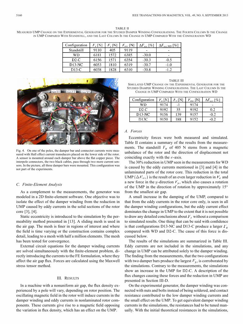
terpole connector currents were positioned at the current arrowsin Fig. 3. The insulation of the damper bars prevented any un-wanted intra- and interpole currents. A photograph of the holderfor the damper winding current sensors can be found in Fig. 4.Data was collected at 10 kHz, which is equivalent to 1200
data points per revolution. Except for the strain gauge signals,which have been amplified, the measurements have not beensubject to filtering or any other form of manipulation. Data col-lected on the rotor side were transferred wirelessly to the sta-tionary logging system and later synchronized with the stator-side data through signals from two optical sensors.
5160 IEEE TRANSACTIONS ON MAGNETICS, VOL. 49, NO. 9, SEPTEMBER 2013
TABLE IIMEASURED UMP CHANGE ON THE EXPERIMENTAL GENERATOR FOR THE STUDIED DAMPER WINDING CONFIGURATIONS. THE FOURTH COLUMN IS THE CHANGE
IN UMP COMPARED WITH STANDSTILL, AND THE LAST COLUMN IS THE CHANGE IN UMP COMPARED WITH THE CONFIGURATION WD
Fig. 4. On one of the poles, the damper bar and connector currents were mea-sured with Hall effect current transducers placed on the lower side of the rotor.A sensor is mounted around each damper bar above the flat copper piece. Theinterpole connectors, the two black cables, pass through two more current sen-sors. In the picture, all three damper bars were mounted. This configuration wasnot part of the experiments.
C. Finite-Element Analysis
As a complement to the measurements, the generator wasmodeled in a 2D finite-element software. One objective was toisolate the effect of the damper winding from the reduction inUMP caused by eddy currents in the solid sections of the rotorcore [3], [4].Static eccentricity is introduced to the simulation by the per-
meability method presented in [13]. A sliding mesh is used inthe air gap. The mesh is finer in regions of interest and wherethe field is time varying or the construction contains complexdetail, leading to a mesh with half a million elements. The meshhas been tested for convergence.External circuit equations for the damper winding currents
are solved simultaneously with the finite-element problem, di-rectly introducing the currents to the FE formulation, where theyaffect the air gap flux. Forces are calculated using the Maxwellstress tensor method.
III. RESULTS
In a machine with a nonuniform air gap, the flux density ex-perienced by a pole will vary, depending on rotor position. Theoscillating magnetic field in the rotor will induce currents in thedamper winding and eddy currents in nonlaminated rotor com-ponents. These currents give rise to a magnetic field opposingthe variation in flux density, which has an effect on the UMP.
TABLE IIISIMULATED UMP CHANGE ON THE EXPERIMENTAL GENERATOR FOR THESTUDIED DAMPER WINDING CONFIGURATIONS. THE LAST COLUMN IS THE
CHANGE IN UMP COMPARED WITH THE CONFIGURATION WD
A. Forces
Eccentricity forces were both measured and simulated.Table II contains a summary of the results from the measure-ments. The standstill of 405 N stems from a magneticunbalance of the rotor and the direction of displacement notcoinciding exactly with the -axis.The 30% reduction in UMP seen in themeasurements forWD
is caused by the eddy currents mentioned in [3] and [4] in theunlaminated parts of the rotor core. This reduction in the totalUMP is the result of an even larger reduction in anda new force in the -direction , which also causes a rotationof the UMP in the direction of rotation by approximately 15from the smallest air gap.A small increase in the damping of the UMP, compared to
that from the eddy currents in the rotor core only, is seen in allthe damper winding configurations, but the eddy current effectdominates the change in UMP to the extent that it is not possibleto draw any detailed conclusions about without a comparisonto simulated results. One thing that can be said with confidenceis that configurations D13-NC and D13-C produce a largercompared with WD and D2-C. The cause of this force is dis-cussed below.The results of the simulations are summarized in Table III.
Eddy currents are not included in the simulations, and anychange in UMP can be attributed solely to the damper winding.The finding from the measurements, that the two configurationswith two damper bars produce the largest , is corroborated bythe simulations. Contrary to the measurements, the simulationsshow an increase in the UMP for D2-C. A description of theflux changes causing these forces and the reduction in UMP arepresented in Section III-D.On the experimental generator, the damper winding was con-
nected with nuts and bolts instead of being soldered, and contactresistance contributed to the low damper winding currents andthe small effect on the UMP. To get equivalent damper windingcurrents in the simulations, the resistances had to be tuned man-ually. With the initial theoretical resistances in the simulations,
WALLIN et al.: DAMPER WINDING INFLUENCE ON UMP IN SALIENT POLE GENERATORS WITH ROTOR ECCENTRICITY 5161
TABLE IVSIMULATED UMP CHANGE ON THE 28-POLE GENERATOR FOR THE STUDIEDDAMPER WINDING CONFIGURATIONS. THE LAST COLUMN IS THE CHANGE
IN UMP COMPARED WITH THE CONFIGURATION WD. ALL SEVENDAMPER BARS PER POLE WERE USED. THE NOTATION WD,
NC, AND C ARE DESCRIBED IN SECTION II-A
D2-C produced a small reduction in , and the effects both onand were larger for all damper configurations.The 28-pole production generator described in Table I was
simulated for comparison. Table IV contains a summary of theresults. For both the continuous and the noncontinuous windingconfigurations, the reduction in UMP is approximately 40%. Inthe simulations, the damper winding resistances on the 28-polegenerator are calculated from the copper resistivity only, i.e.,they do not contain any contact resistances, resulting in higherdamper winding currents and a larger effect on the UMP. Ona real production generator, the damper winding joints are sol-dered, which also results in low connection resistances. Anothercause for the larger effect of the damper winding on the 28-polegenerator is that the damper bars span a large proportion of thepole shoe width.In a production generator, the rotor spider is normally lam-
inated so the effect of eddy currents in the iron will be smallcompared with their relative size on the experimental generator.Taken together, the laminated rotor spider, the lower damper
winding resistance, and the larger damper bar distance resultin a higher effect of the damper winding relative to the ironeddy currents on a production machine compared with on theexperimental generator.On the experimental generator, the effect on the eccentricity
forces from the damper winding was so small that a compar-ison between the damper bars positioned in slots 1 and 2 andslots 1 and 3 would not have produced a significant change inthe UMP. Instead, the effect of damper bar separation was in-vestigated through simulations. Fig. 5 contains the results. Con-tact resistances were not included, and material resistivity onlywas used to calculate the damper winding resistance for thesesimulations. The damper winding resistance thus obtained wasless than a fourth of the actual resistance on the experimentalgenerator.The pole body width is 3.5 , and it can be seen that the pos-
itive effect of an increasing damper bar distance starts to taperoff as this value is approached. The forces at 2.2 in Fig. 5 givean indication of what the changes in UMP would have been inthe experiments had the damper winding had a negligible con-tact resistance.
B. Flux Density
Three different flux density measurements for the caseD13-NC are shown in Fig. 6. comes from the first rotorflux density sensor. The main feature of the graph is that theflux density is higher where the air gap is small, but it can also
Fig. 5. Simulated UMP reduction as a function of damper bar separation ata relative eccentricity of 0.44. To show the effect of the damper bar distancemore clearly these simulations were performed with a lower damper windingresistance than the simulations described in the tables. Distances are given inthe stator slot pitch . The tick marks on the -axis are the distances simulated.Zero indicates the absence of a damper winding.
Fig. 6. The air gap flux density for D13-NC. See Figs. 1 and 2 for the positionsof the sensors.
be seen that the small air gap gives rise to larger stator slotharmonics.The two other graphs are from the two sensors attached to
the inside of the stator. ’s three small grooves around theamplitude 0.5 T are caused by the damper bar slots in the poleshoes. As with the slot ripple in the rotor signal, this effect ismore pronounced where the air gap is small; it can barely beseen in the signal of . The reduction in flux density in thecenter of the poles is discussed in Section III-D.The flux density is a function of the permeance, , which
is inversely proportional to the air gap length , according to. Since and is constant, this
can after differentiation be solved directly for the ’s whichprovide the highest rate of change of . According to Faraday’s
5162 IEEE TRANSACTIONS ON MAGNETICS, VOL. 49, NO. 9, SEPTEMBER 2013
law, this is, ignoring other effects, where the induced damperwinding voltages will be largest. With , the positionsof the maximum absolute rate of change of the permeance are47 and 47 . If the relative eccentricity is less than 0.44, the
positions of maximum rate of change will occur at angles largerthan 47 from the smallest air gap.Measurements place themaxima near 55 . Inspection of the
rising and falling flanks of in Fig. 6 show that the steepestsections are near these angles as well. Two explanations for thediscrepancy are an error in the true relative eccentricity duringmeasurements and iron eddy currents.The variation in introduces a time-varying flux density in
the rotor. In the experimental generator with its solid rotor core,this will result in large eddy currents, which will cause a flat-tening of the flux density curve and also move the points ofhighest rate of change in the flux away from the smallest airgap. The eddy currents reduce the UMP present at standstill.Due to the radial rigidity of the experimental setup and the
large effect of the eddy currents on the UMP, the eddy currentsrather than any inaccuracy in the setting of the eccentricity arebelieved to be the main cause of the shift in the positions ofmaximum rate of change of flux density.Another effect seen here, and even more clearly in the case
without damper winding, is the increased flux density towardsthe tail end of the poles. Since the measurements are performedwith open terminals, this distortion of the magnetic field is at-tributed to losses distorting the magnetic field. The fact that theslanting is more prominent in the small air gap, where the slotripple will cause larger eddy currents in the metal near the airgap, supports this conclusion.
C. Damper Winding Currents
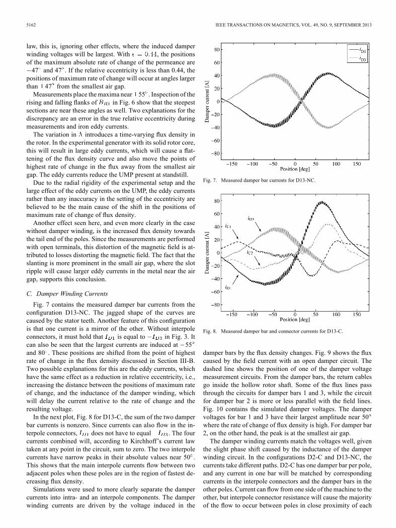
Fig. 7 contains the measured damper bar currents from theconfiguration D13-NC. The jagged shape of the curves arecaused by the stator teeth. Another feature of this configurationis that one current is a mirror of the other. Without interpoleconnectors, it must hold that is equal to in Fig. 3. Itcan also be seen that the largest currents are induced at 55and 80 . These positions are shifted from the point of highestrate of change in the flux density discussed in Section III-B.Two possible explanations for this are the eddy currents, whichhave the same effect as a reduction in relative eccentricity, i.e.,increasing the distance between the positions of maximum rateof change, and the inductance of the damper winding, whichwill delay the current relative to the rate of change and theresulting voltage.In the next plot, Fig. 8 for D13-C, the sum of the two damper
bar currents is nonzero. Since currents can also flow in the in-terpole connectors, does not have to equal . The fourcurrents combined will, according to Kirchhoff’s current lawtaken at any point in the circuit, sum to zero. The two interpolecurrents have narrow peaks in their absolute values near 50 .This shows that the main interpole currents flow between twoadjacent poles when these poles are in the region of fastest de-creasing flux density.Simulations were used to more clearly separate the damper
currents into intra- and an interpole components. The damperwinding currents are driven by the voltage induced in the
Fig. 7. Measured damper bar currents for D13-NC.
Fig. 8. Measured damper bar and connector currents for D13-C.
damper bars by the flux density changes. Fig. 9 shows the fluxcaused by the field current with an open damper circuit. Thedashed line shows the position of one of the damper voltagemeasurement circuits. From the damper bars, the return cablesgo inside the hollow rotor shaft. Some of the flux lines passthrough the circuits for damper bars 1 and 3, while the circuitfor damper bar 2 is more or less parallel with the field lines.Fig. 10 contains the simulated damper voltages. The dampervoltages for bar 1 and 3 have their largest amplitude near 50where the rate of change of flux density is high. For damper bar2, on the other hand, the peak is at the smallest air gap.The damper winding currents match the voltages well, given
the slight phase shift caused by the inductance of the damperwinding circuit. In the configurations D2-C and D13-NC, thecurrents take different paths. D2-C has one damper bar per pole,and any current in one bar will be matched by correspondingcurrents in the interpole connectors and the damper bars in theother poles. Current can flow from one side of themachine to theother, but interpole connector resistance will cause the majorityof the flow to occur between poles in close proximity of each
WALLIN et al.: DAMPER WINDING INFLUENCE ON UMP IN SALIENT POLE GENERATORS WITH ROTOR ECCENTRICITY 5163
Fig. 9. Magnetic field from rotor field current. The positions of maximum rateof change of flux density are indicated by the two arrows.
Fig. 10. Simulated open circuit damper bar voltages.
other. D13-NC does not have any interpole connectors and thecurrents in the two damper bars will have the same amplitudebut the opposite sign, as seen in Fig. 7.Fig. 11 shows the damper bar currents produced in configu-
rations D2-C and D13-NC fitted to the current from D13-C. ForD13-NC and D13-C, the leading rod was used. Even though theresulting coefficients are not equal to one, the good fit indicatesthat the currents in D13-C has two distinct origins: inter- andintrapole effects.
D. Damper Winding Current Effect on Air Gap Flux andEccentricity Force
The reduced flux density in the centre of the poles in graphin Fig. 6 is an effect of intrapole damper winding currents.
In this case, the currents create a flux opposing the increase influx density as the pole approaches the smallest air gap. Sincethe currents lag the induced voltage, the effect remains even atthe smallest air gap, where the difference between the voltagesinduced in bars 1 and 3 is zero.
Fig. 11. Simulated current components.
Fig. 12. Simulated normal air gap flux density induced by the damper windingcurrents only, i.e. with the field current set to zero. The rotor position for thisplot can be seen in Figs. 13 and 14.
To isolate the flux caused by the damper winding currents,stationary simulations were performed where the field currentwas set to zero and the damper bar currents were set to thevalues given by the simulations of D2-C and D13-NC presentedin Table III. Fig. 12 displays the resulting flux densities.As a consequence of the changing air gap length, the direc-
tion of the damper induced flux changes relative to the fieldflux twice per revolution. For D2-C, this happens at 45 and65 , while, for D13-NC, it takes place close to the smallest andlargest air gaps near 0 and 180 . Figs. 13 and 14 show the fieldlines for these current distributions. In both cases, there is somedamper slot leakage that do not contribute to the reduction inUMP. In several poles, the configuration D2-C generates a fluxthat goes from the pole to the stator and closes in the same pole.This results in a reduction of the field induced flux in one part ofthe pole and an increase of the flux in another part of the pole.Theoretically, the net effect should be an increase in the UMPsince .The tangential component of Maxwell’s stress tensor caused
by the damper winding did not significantly alter the UMP and is
5164 IEEE TRANSACTIONS ON MAGNETICS, VOL. 49, NO. 9, SEPTEMBER 2013
Fig. 13. Flux distribution caused by the current in the damper winding withone bar per pole and interpole connectors (D2-C).
Fig. 14. Flux distribution caused by the current in the damper winding withtwo bars per pole and no interpole connectors (D13-NC).
omitted below. The normal stress for any air gap circumferenceincrement is calculated as , where
and are the flux densities caused by the field currentand damper winding current respectively. will be small,but the double product, , reduces the modulation ofthe normal stress around the air gap. Measurements and simu-lations were done at flux densities well below saturation so thecombination of the rotor field and damper induced fluxes shouldbe linear. Fig. 15 shows the incremental normal force compo-nents calculated from only. The resulting total forcecan be calculated through integration around the air gap.Both the increasing and decreasing nature of the flux contri-
bution from D2-C makes the analysis of the effect on the UMPdifficult, but Table III shows that there is, in fact, a slight in-crease in the UMP.D13-NC gives rise to forces in the opposite direction of the
UMP in the upper and lower right part of the graph, which, taken
Fig. 15. Incremental eccentricity force caused by double product of the damperwinding normal flux and the rotor field flux, . The rotor position forthis plot can be seen in Figs. 13 and 14.
together, result in a reduction of the UMP and a tangential forcecomponent.
IV. DISCUSSION
The effect of the damper winding on the UMP was small rel-ative to that of the eddy currents in the solid parts of the rotorcore. On the experimental generator only the outermost few cen-timeters on each pole was laminated [12], and this is believedto be the cause of the large eddy current effects seen in Table II.Another reason for the large eccentricity required to give any
measurable effect of the damper winding on the UMP is that thedamper bars in the experimental generator only cover a smallpart of the pole width and have high contact resistances. The re-duction of unbalanced magnetic pull from the damper windingis strongly dependent on the distance between the leading andtrailing damper bars and the damper winding resistance. Givenunfavorable characteristics, the effect on UMP from a damperwinding could be smaller than from saturation, investigated by[2], parallel connections in the stator [3], [14]–[16], or, in a solidrotor, eddy currents [3], [4] for a given eccentricity. Other pa-rameters influencing the effect of a damper winding on UMP iswhether the rotor has unlaminated sections, in which case eddycurrents will contribute to the reduction of UMP, the air gaplength, and the rotational speed of the generator.
V. CONCLUSION
The effect of damper winding configuration on unbalancedmagnetic pull has been measured and simulated. Even thoughvery large relative eccentricity was used, the effect of thedamper winding on the eccentricity forces was small. Onereason for this was a high damper winding resistance. Mea-surements revealed that eddy currents in the solid rotor corecontribute significantly more to the reduction of the eccentricityforces in a machine with a solid rotor spider. Simulations pre-sented showed a strong dependence, in the relevant range, ofdamper bar opening on the reduction in UMP.
WALLIN et al.: DAMPER WINDING INFLUENCE ON UMP IN SALIENT POLE GENERATORS WITH ROTOR ECCENTRICITY 5165
ACKNOWLEDGMENT
The research presented was carried out as a part of “SwedishHydropower Centre (Svenskt Vattenkraft Centrum)—SVC”.SVC has been established by the Swedish Energy Agency,Elforsk, and Svenska Kraftnät, together with the Luleå Uni-versity of Technology, The Royal Institute of Technology,Chalmers University of Technology, and Uppsala University(website: www.svc.nu). The work of J. Bladh and U. Lundin issupported by SVC. The work of M. Wallin is financed withinElektra, a research program created by ABB, Elforsk, and theSwedish Energy Agency. This work was supported in part byCarl Tryggers Stiftelse. The motor that the generator used inthe experiments was based on was donated by Svante Leonssonat GE Hydro, Kristinehamn.
REFERENCES[1] A. Arkkio, “Unbalanced magnetic pull in cage induction motors with
asymmetry in rotor structures,” in Proc. 8th Int. Electr. Mach. DrivesConf. (IEMDC), Sep. 1997, pp. 36–40, Conf. Publ. No. 444.
[2] R. Perers, U. Lundin, and M. Leijon, “Saturation effects on unbalancedmagnetic pull in hydroelectric generator with an eccentric rotor,” IEEETrans. Magn., vol. 43, no. 10, pp. 3884–3890, Oct. 2007.
[3] M. Wallin, M. Ranlof, and U. Lundin, “Reduction of unbalancedmagnetic pull in synchronous machines due to parallel circuits,” IEEETrans. Magn., vol. 47, no. 12, pp. 4827–4833, Dec. 2011.
[4] T. Bratoljić and P. Vrkljan, “Magnetic forces created by rotor eccen-tricity in electrical machines,” Brown Boveri Rev., vol. 54, no. 9, pp.580–592, 1967.
[5] S. Keller, M. Xuan, J.-J. Simond, and A. Schwery, “Large low-speedhydro-generators-unbalanced magnetic pulls and additional damperlosses in eccentricity conditions,” IET Electr. Power Appl., vol. 1, no.5, pp. 657–664, 2007.
[6] A. Burakov and A. Arkkio, “Comparison of the unbalanced magneticpull mitigation by the parallel paths in the stator and rotor windings,”IEEE Trans. Magn., vol. 43, no. 12, pp. 4083–4088, Dec. 2007.
[7] D. Dorrell, J. Shek, M.-F. Hsieh, and M. Mueller, “Unbalanced mag-netic pull in cage induction machines for fixed-speed renewable energygenerators,” IEEE Trans. Magn., vol. 47, no. 10, pp. 4096–4099, Oct.2011.
[8] S. Jovanovski, “Calculation and testing of damper-winding current dis-tribution in a synchronous machine with salient poles,” IEEE Trans.Power App. Syst., vol. PAS-88, no. 11, pp. 1611–1619, Nov. 1969.
[9] M. Rahimian and K. Butler-Purry, “Modeling of synchronous ma-chines with damper windings for condition monitoring,” in Proc. IEEEInt. Electr. Mach. Drives Conf. (IEMDC), May 2009, pp. 577–584.
[10] J. Matsuki, T. Katagi, and T. Okada, “Slot ripples in the damper wind-ings of a salient-pole synchronous generator,” IEEE Trans. EnergyConvers., vol. 9, no. 1, pp. 126–134, Mar. 1994.
[11] A. Darabi and C. Tindall, “Damper cages in genset alternators: Fe sim-ulation and measurement,” IEEE Trans. Energy Convers., vol. 19, no.1, pp. 73–80, Mar. 2004.
[12] M. Wallin, M. Ranlöf, and U. Lundin, “Design and construction of asynchronous generator test setup,” presented at the Int. Conf. Electr.Mach., Rome, Italy, Sep. 2010.
[13] U. Lundin and A. Wolfbrandt, “Method for modelling time-dependentnonuniform rotor/stator configurations in electrical machines,” IEEETrans. Magn., vol. 45, no. 7, pp. 2976–2980, Jul. 2009.
[14] D. Dorrell and A. Smith, “Calculation of UMP in inductionmotors withseries or parallel winding connections,” IEEE Trans. Energy Convers.,vol. 9, no. 2, pp. 304–310, Jun. 1994.
[15] O. W. Andersen, “Compensation of unbalanced magnetic forces bydistributed parallel circuits,” presented at the Int. Conf. Electr. Mach.(ICEM), Krakow, Poland, Aug. 2004.
[16] W. Oliveira, M. Uemori, J. Rocha, and R. Carlson, “Reduction ofunbalanced magnetic pull (UMP) due to equipotential connectionsamong parallel circuits of the stator winding,” in Proc. Int. Electr.Mach. Drives Conf. (IEMDC), May 2009, pp. 771–777.
Mattias Wallin received the M.Sc. degree in mechanical engineering from theRoyal Institute of Technology, Stockholm, Sweden, in 2008.He is currently working towards the Ph.D. degree at the Department of En-
gineering Sciences at Uppsala University, Uppsala, Sweden. His main researchinterest is the electromechanical interactions in hydropower generators.
Johan Bladh received the M.Sc. degree in engineering physics from UppsalaUniversity, Uppsala, Sweden, in 2007.He is currently working at the Department of Power Technology at Vattenfall
Research & Development AB, Älvkarleby, Sweden, and working towards thePh.D. degree at Uppsala University. His main research interest is hydropowergenerators and power system dynamics.
Urban Lundin received the Ph.D. degree in condensed matter theory, with afocus on models of strongly correlated electrons, from Uppsala University, Up-psala, Sweden, in 2000.From 2001 to 2004, he worked on transport properties of nanostructures under
the influence of magnetic fields at the University of Queensland, Brisbane, Aus-tralia. In 2004, he took up a position as a Senior Lecturer and Researcher atUppsala University, with a focus on energy conversion systems, mainly for hy-dropower applications.