Turkish Journal of Electrical Engineering & Computer Sciences
http :// journa l s . tub i tak .gov . t r/e lektr ik/
Research Article
Damping of low-frequency oscillation in power systems using hybrid renewableenergy power plants
Mahdi SAADATMAND1, Babak MOZAFARI1∗, Gevork B. GHAREHPETIAN2,Soodabeh SOLEYMANI1
1Department of Electrical Engineering, Science and Research Branch, Islamic Azad University, Tehran, Iran2Department of Electrical Engineering, Amirkabir University of Technology, Tehran, Iran
Received: 04.12.2018 • Accepted/Published Online: 27.05.2019 • Final Version: 18.09.2019
Abstract: Global warming, increase in environmental pollution, and high cost of electrical power generation usingfossil fuels are considered the most important reasons for the application of renewable energy power plants (REPPs)around the world. In recent years, a new generation of REPPs called hybrid renewable energy power plants (HREPPs)has been implemented in order to have higher efficiency and reliability than conventional REPPs such as wind powerplants and photovoltaic power plants. The HREPPs include two or more renewable energy generation units such aswind turbine generation units, and PV generation units. In case of high penetration of these types of power plants,the most common tasks of synchronous generators should be supported by them. One of these tasks is the ability toreduce the low-frequency oscillation (LFO) risk through power oscillation damper such as the power system stabilizersof synchronous generators. In this paper, a novel method is proposed for LFO damping by HREPPs, which is based onthe design of an optimal power oscillation damper (OPOD) implemented in the generic HREPP controller model. Thestructure of the proposed OPOD is a 2nd-order single-input lead-lag controller, and its performance is investigated in amodified two-area test system. The simulation results show the proper performance of the HREPP for LFO dampingusing the proposed OPOD in the various loading levels and different short circuit ratio values.
Key words: Hybrid renewable energy power plant, low-frequency oscillation, optimal power oscillation damper, photo-voltaic generation, renewable energy generation unit, wind turbine generation, short circuit ratio
1. IntroductionThe use of fossil fuels such as coal, natural gas, and crude oil, along with their harmful effects on global warmingand environmental pollution, involves great costs for modern societies. Therefore, countries have had a strongtendency to use renewable energies, especially after the oil crisis met in 1970s [1]. Today, a growing trend canbe seen in establishing and exploiting renewable energy power plants (REPPs). These power plants are usuallyadded to the power system to increase the generation capacity. Moreover, they replace conventional powerplants in some cases [2, 3]. The hybrid renewable energy power plants (HREPPs) are a new type of REPPswhich are extensively used in the near future considering their higher efficiency and reliability, compared tothe conventional REPPs [1, 2]. However, various types of HREPPs are established in small-scale in differentparts of the world. Despite the various benefits of the renewable energies, some of the intrinsic characteristicsof these energy sources are barriers for the lack of access to a high efficiency and reliability [1]. For example,∗Correspondence: [email protected]
This work is licensed under a Creative Commons Attribution 4.0 International License.3852
SAADATMAND et al./Turk J Elec Eng & Comp Sci
noneverlasting winds at the proper speed and the lack of effective sunshine at different times are some of theissues which can reduce the generation efficiency in REPPs. The HREPP is regarded as a fundamental solutionto increase the efficiency and reliability [4]. For example, the hybrid use of wind turbine generations (WTGs) andphotovoltaic generations (PVGs) increases the efficiency and reliability of electrical power generation, comparedto the separated application of photovoltaic power plant (PPP) or wind power plant (WPP) [1].
The HREPPs consist of two or more renewable energy generation units (REGUs). The structure of thistype of power plant is such that they can use static VAR systems such as SVC and STATCOM in some cases[5]. The most common structure of these power plants is related to the hybrid structure of WTG and PVGunits. From control point of view, HREPPs include separate controllers related to each REGU and a centralcontroller, as well. In order to establish and exploit REPPs, two main issues should be taken into consideration.First, the entrance of these power plants into power systems causes many changes in the characteristics ofthese systems such as stability [6–12]. Second, given the replacement of these types of power plants with theconventional power plants, many of the existing capabilities in the synchronous generators, such as voltageregulation, frequency regulation, and low-frequency oscillation (LFO) damping by the power system stabilizer(PSS) should be obtained by them. Given that REPPs are connected to the power system by the inverter,they lack mechanical inertia; therefore, they have negative effect on the LFO damping in case of replacementwith power plant with PSS. Moreover, their entrance may affect the flow of the lines, which are effective on theLFO damping [3, 11]. Thus, the REPPs need to be able to damp the LFO through the auxiliary controllers.In many papers, the LFO damping through the PPPs and WPPs has been studied [13–17], but so far no studyhas been conducted on damping of LFO by HREPPs. Given that the HREPP controller model is different fromthe controller model of WPP and PPP, it is necessary to study this issue separately.
In this paper, a novel method is proposed for LFO damping by HREPPs, which is based on the design ofan optimal power oscillation damper (OPOD) implemented in the generic HREPP controller model (GHCM).The OPOD is a 2nd-order single-input lead-lag controller which is implemented in the central controller of theHREPP. The OPOD parameters are determined using the particle swarm optimization algorithm. In order tooptimize and determine the parameters, an objective function (OF) is defined for a wide range of loading andfault conditions. Given that the HREPP dynamic model is a strongly nonlinear model, the OF is defined as anonlinear function in the time-domain. The remainder of the paper is organized as follows: Section 2 gives abrief overview on the HREPP model for stability studies. Section 3 introduces the structure of the proposedOPOD and the studied power system. The design method of the proposed OPOD is presented in Section4. The performance evaluation of the HREPP using the OPOD, in order to increase the LFO damping andtime-domain analysis, is elaborated in Section 5. Finally, the conclusions are drawn in Section VI.
2. HREPP model for stability studies
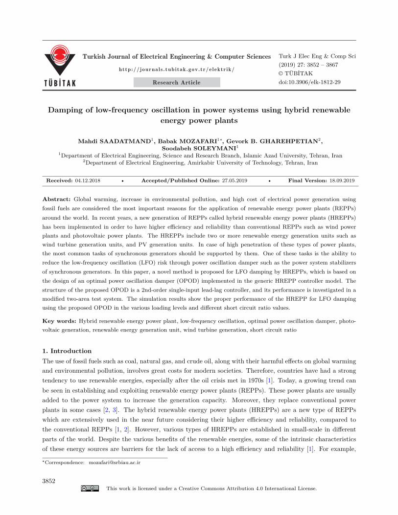
Generally, each REPP consists of three essential components including energy converter such as PV arrays orturbine generators, inverters, and controllers. The HREPPs also have these three components, but they use twoor more types of REGUs [5]. In these power plants, each REGU has its own special controller. Each REGUcontroller receives command signals from a central controller [5]. Figure 1 illustrates the HREPP includingPVG and WTG units. Given that the converter-based units are connected to the grid by the inverters, theirdynamic is too fast and can usually be ignored in stability studies. Thus, their converted energy is assumed tobe constant [18–21].
3853
SAADATMAND et al./Turk J Elec Eng & Comp Sci
Figure 1. HREPP including PVG and WTG units.
It should be noted that the inverter of the REPP is modeled as a current-controlled current source in thepower system stability analysis. In some power system software such as DIgSILENT PowerFactory, this modelis available as static generator. As mentioned, the third component of REPPs is the controllers, which play afundamental role in the system response during dynamic state. Thus, the modeling of the HREPPs controllingsystem is essential for power system analysis.
2.1. HREPP model for steady-state studies
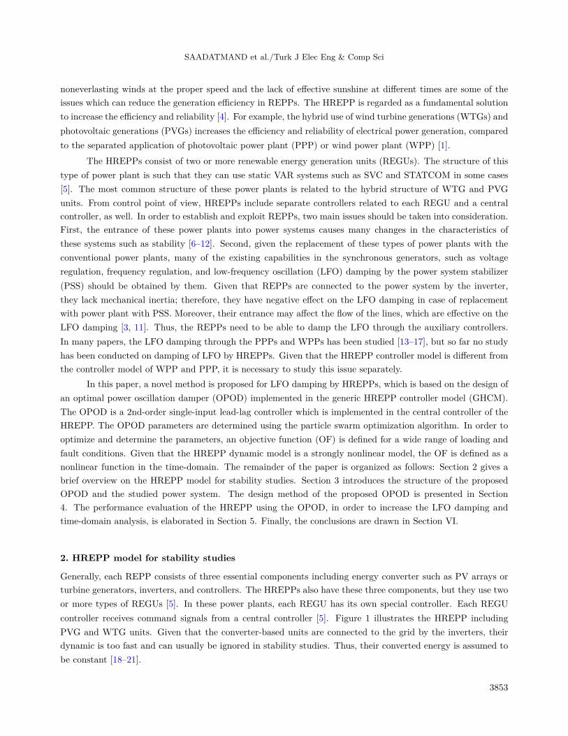
In order to conduct any study on a power system, an overview of the steady-state of the system should beconsidered. Therefore, a model should be first available for this state. As mentioned, the HREPPs consist oftwo or more REGUs, each of which includes smaller units. For example, a PVG unit includes many photovoltaic(PV) panels and inverters. In order to conduct steady-state studies, the total number of REGUs is necessaryto be considered an equivalent REGU in which its rated power is equal to the sum of the rated powers ofindividual REGUs. This model is called simple aggregated model [18–21]. As shown in Figure 2, the simpleaggregated model can be used for stability analysis, and each REGU is considered as a conventional generatorfor the HREPP which involves PVG and WTG units. The connecting point of power plant to the grid is calledpoint of common coupling (PCC).
2.2. Generic model of HREPPs for dynamic studies
First, the models presented in [22] have been used. These models had their own problems although they couldsatisfy the study requirements in many cases. However, the lack of a generic, accessible, and flexible model,which could be used for a variety of REPPs, was evident before expanding the establishment and developmentof REPPs [5]. Although different models have been presented by well-known companies and institutes later[14–17], the model introduced by Western Electricity Coordinating Council (WECC), called first-generationgeneric model, is regarded as the leading one [19]. Since 2010, WECC has initiated to develop this model forfurther flexibility and adapt it to a wide range of control strategies for the possibility of modeling different typesof equipment for power plants. The result was second generation generic model (SGGM) presented in 2012 [18].
3854
SAADATMAND et al./Turk J Elec Eng & Comp Sci
Figure 2. A simple aggregated model of HREPP [17, 20].
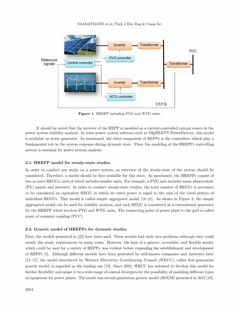
Due to the increasing tendency to use the HREPPs, WECC and Electric Power Research Institute (EPRI)conducted some studies to present a generic model for this type of power plants. Ultimately, an initial modelcalled GHCM was presented by them in 2016 [5, 21]. This model, which is based on the SGGM, is currentlyunder development [5]. The modular structure of this model is shown in Figure 3, and used in this study.
Figure 3. Modular structure of GHCM [5, 21].
As illustrated, this model includes three control modules [5, 21]:• The renewable energy generator/converter_a (regc_a).• The renewable energy electrical control_b (reec_b).• The renewable energy plant control_b (repc_b), called central controller model.
3. Proposed model of HREPP for LFO dampingAs mentioned, these power plants should be capable of LFO damping in the grid through auxiliary controllersdue to ever-increasing number of HREPPs and their replacement with conventional power plants. Therefore,
3855
SAADATMAND et al./Turk J Elec Eng & Comp Sci
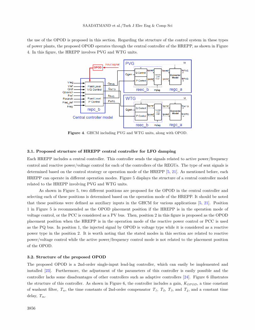
the use of the OPOD is proposed in this section. Regarding the structure of the control system in these typesof power plants, the proposed OPOD operates through the central controller of the HREPP, as shown in Figure4. In this figure, the HREPP involves PVG and WTG units.
Figure 4. GHCM including PVG and WTG units, along with OPOD.
3.1. Proposed structure of HREPP central controller for LFO damping
Each HREPP includes a central controller. This controller sends the signals related to active power/frequencycontrol and reactive power/voltage control for each of the controllers of the REGUs. The type of sent signals isdetermined based on the control strategy or operation mode of the HREPP [5, 21]. As mentioned before, eachHREPP can operate in different operation modes. Figure 5 displays the structure of a central controller modelrelated to the HREPP involving PVG and WTG units.
As shown in Figure 5, two different positions are proposed for the OPOD in the central controller andselecting each of these positions is determined based on the operation mode of the HREPP. It should be notedthat these positions were defined as auxiliary inputs in the GHCM for various applications [5, 21]. Position1 in Figure 5 is recommended as the OPOD placement position if the HREPP is in the operation mode ofvoltage control, or the PCC is considered as a PV bus. Then, position 2 in this figure is proposed as the OPODplacement position when the HREPP is in the operation mode of the reactive power control or PCC is usedas the PQ bus. In position 1, the injected signal by OPOD is voltage type while it is considered as a reactivepower type in the position 2. It is worth noting that the stated modes in this section are related to reactivepower/voltage control while the active power/frequency control mode is not related to the placement positionof the OPOD.
3.2. Structure of the proposed OPODThe proposed OPOD is a 2nd-order single-input lead-lag controller, which can easily be implemented andinstalled [23]. Furthermore, the adjustment of the parameters of this controller is easily possible and thecontroller lacks some disadvantages of other controllers such as adaptive controllers [24]. Figure 6 illustratesthe structure of this controller. As shown in Figure 6, the controller includes a gain, KOPOD, a time constantof washout filter, Tw, the time constants of 2nd-order compensator T1, T2, T3, and T4, and a constant timedelay, Tm.
3856
SAADATMAND et al./Turk J Elec Eng & Comp Sci
Figure 5. HREPP central controller model including PVG and WTG units along with OPOD.
Figure 6. 2nd-order single-input lead-lag controller for OPOD.
Regarding the selected signal types as inputs to this OPOD, a wide area measurement system shouldbe expanded by using a secure communication technology [25]. To this aim, the application of the phasormeasurement units (PMUs) installed in the buses related to synchronous generators is essential to measure thenecessary signals. In addition, since there is a delay in sending measured signals from each bus to the controllerinput, the constant time delay, Tm, is used to consider this issue [26].
4. Test system and OPOD design
4.1. Test system
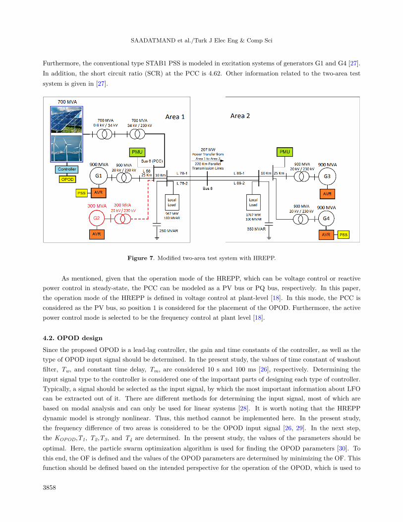
In this paper, the modified two-area test system is considered as a benchmark system to conduct this study.As shown in Figure 7, this system includes three synchronous generators which are modeled by a sixth orderdynamic model. Furthermore, the HREPP is connected to the bus 6 and replaces generator G2. The rating ofHREPP is 700 MVA, in which 400 MVA and 300 MVA are related to the PVG and WTG units, respectively.Each of these three synchronous generators is equipped with simplified IEEE type ST1A excitation system.
3857
SAADATMAND et al./Turk J Elec Eng & Comp Sci
Furthermore, the conventional type STAB1 PSS is modeled in excitation systems of generators G1 and G4 [27].In addition, the short circuit ratio (SCR) at the PCC is 4.62. Other information related to the two-area testsystem is given in [27].
Figure 7. Modified two-area test system with HREPP.
As mentioned, given that the operation mode of the HREPP, which can be voltage control or reactivepower control in steady-state, the PCC can be modeled as a PV bus or PQ bus, respectively. In this paper,the operation mode of the HREPP is defined in voltage control at plant-level [18]. In this mode, the PCC isconsidered as the PV bus, so position 1 is considered for the placement of the OPOD. Furthermore, the activepower control mode is selected to be the frequency control at plant level [18].
4.2. OPOD design
Since the proposed OPOD is a lead-lag controller, the gain and time constants of the controller, as well as thetype of OPOD input signal should be determined. In the present study, the values of time constant of washoutfilter, Tw, and constant time delay, Tm, are considered 10 s and 100 ms [26], respectively. Determining theinput signal type to the controller is considered one of the important parts of designing each type of controller.Typically, a signal should be selected as the input signal, by which the most important information about LFOcan be extracted out of it. There are different methods for determining the input signal, most of which arebased on modal analysis and can only be used for linear systems [28]. It is worth noting that the HREPPdynamic model is strongly nonlinear. Thus, this method cannot be implemented here. In the present study,the frequency difference of two areas is considered to be the OPOD input signal [26, 29]. In the next step,the KOPOD,T1, T2,T3, and T4 are determined. In the present study, the values of the parameters should beoptimal. Here, the particle swarm optimization algorithm is used for finding the OPOD parameters [30]. Tothis end, the OF is defined and the values of the OPOD parameters are determined by minimizing the OF. Thisfunction should be defined based on the intended perspective for the operation of the OPOD, which is used to
3858
SAADATMAND et al./Turk J Elec Eng & Comp Sci
maximize the LFO damping and minimize the settling times and overshoots during LFO.In this paper, the OF is defined based on the integral of the time-weighted absolute error (ITAE)
performance index, given that the design of the OPOD and the performance analysis of the HREPP are studiedin the time-domain, and all generators are affected [31]. For this purpose, a three-phase short-circuit at themiddle bus (bus 8) is defined for 67 ms (4 cycle) duration as a large disturbance for three loading levels. TheOF is defined as follows [32]:
where NL represents the number of loading levels and tsim indicates the duration of the simulation, which isconsidered to be 20 s. In order to maintain the power system stability while performing optimization simulations,it is necessary to observe the constraints for the optimization parameters as follows:
KOPODmin < KOPOD < KOPOD
max, (3)
Timin < Ti < Ti
max. (4)
The values of the parameter constraints are given in Table 1.
Table 1. Constraints of the OPOD parameters.
Parameters Lower band Upper bandKOPOD 10 100Ti, i ∈ {1, 2, 3, 4} 0.1 5
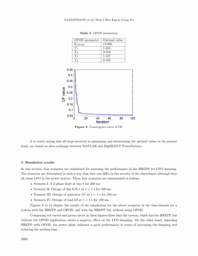
As mentioned, the OF is calculated at different loading levels. Table 2 indicates the different loadinglevels defined in the present study, which are determined with respect to the steady-state stability limit. Inorder to achieve high efficiency in optimization, the number of iterations, the number of particles, the size ofeach particle, c1, c2, wmax, wmin, and c are chosen as 100, 10, 5, 2, 2, 0.9, 0.4, and 1, respectively. Table 3indicates the obtained optimal values of the OPOD parameters by executing the optimization algorithm steps.Figure 8 displays the convergence curve of the OF for determining the OPOD parameters. As shown, the bestvalue of the OF is 0.056988.
Table 2. System loading levels (pu).
Loading level Loads (L7 and L9)Level 1 Nominal loadingLevel 2 90% of nominal loadingLevel 3 110% of nominal loading
It is worth noting that all steps involved in optimizing and determining the optimal values in the presentstudy are based on data exchange between MATLAB and DIgSILENT PowerFactory.
5. Simulation results
In this section, four scenarios are considered for assessing the performance of the HREPP for LFO damping.The scenarios are determined in such a way that they can differ in the severity of the disturbance although theyall cause LFO in the power system. These four scenarios are summarized as follows:
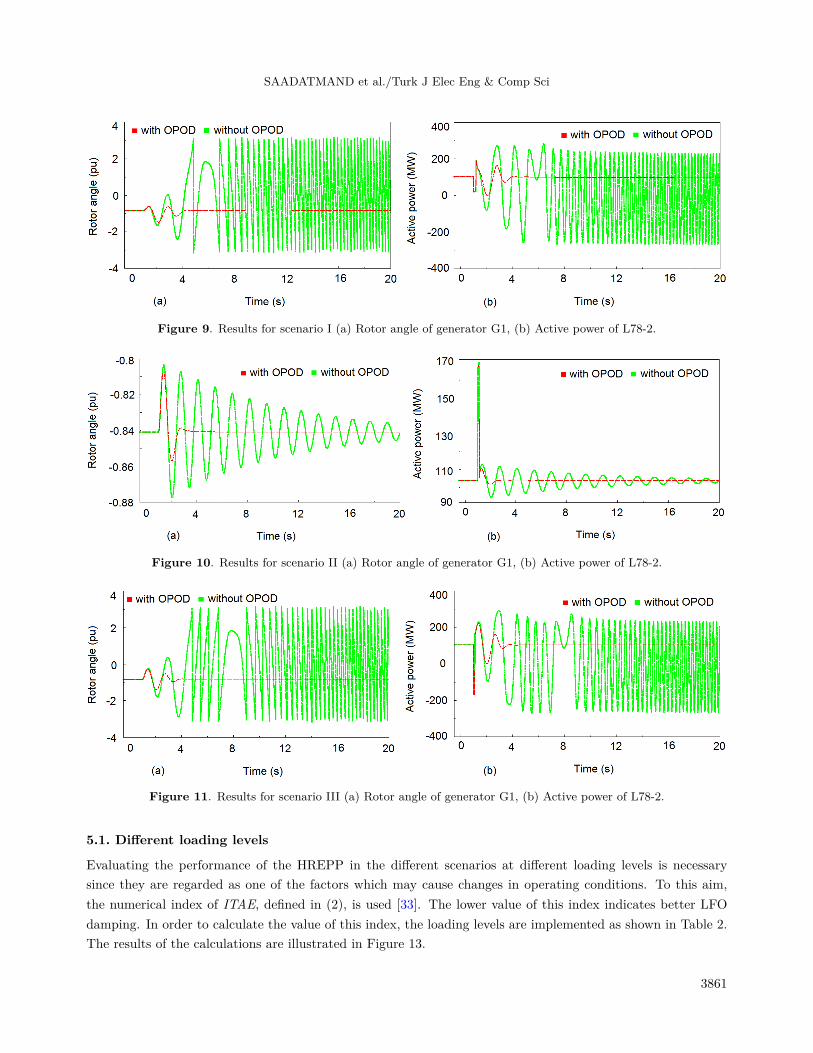
• Scenario I: A 3-phase fault at bus 8 for 200 ms.• Scenario II: Outage of line L78-1 at t = 1 s for 100 ms.• Scenario III: Outage of generator G1 at t = 1 s for 100 ms.• Scenario IV: Outage of load L9 at t = 1 s for 100 ms.Figures 9 to 12 display the results of the simulations for the above scenarios in the time-domain for a
system with the HREPP and OPOD, and with the HREPP but without using OPOD.Comparing red curves and green curves in these figures show that the system, which has the HREPP but
without the OPOD application, shows a negative effect on the LFO damping. On the other hand, regardingHREPP with OPOD, the power plant indicates a good performance in terms of increasing the damping andreducing the settling time.
3860
SAADATMAND et al./Turk J Elec Eng & Comp Sci
Figure 9. Results for scenario I (a) Rotor angle of generator G1, (b) Active power of L78-2.
Figure 10. Results for scenario II (a) Rotor angle of generator G1, (b) Active power of L78-2.
Figure 11. Results for scenario III (a) Rotor angle of generator G1, (b) Active power of L78-2.
5.1. Different loading levels
Evaluating the performance of the HREPP in the different scenarios at different loading levels is necessarysince they are regarded as one of the factors which may cause changes in operating conditions. To this aim,the numerical index of ITAE, defined in (2), is used [33]. The lower value of this index indicates better LFOdamping. In order to calculate the value of this index, the loading levels are implemented as shown in Table 2.The results of the calculations are illustrated in Figure 13.
3861
SAADATMAND et al./Turk J Elec Eng & Comp Sci
Figure 12. Results for scenario IV (a) Rotor angle of generator G1, (b) Active power of L78-2.
Figure 13. ITAE index; (a) scenario I, (b) scenario II, (c) scenario III, (d) scenario IV.
Regarding the comparison of the graphs, the positive effect of the HREPP with the OPOD is confirmedfor LFO damping.
5.2. Different SCR valuesTypically, the system strength is evaluated by the SCR. The SCR is defined as follows [35]:
SCRPCC =SCMVAPCCMWHREPP
, (5)
where SCMVAPCC is the short circuit MVA level at the PCC without the current contribution of the HREPP,and MWHREPP is the nominal active power rating of the HREPP being connected at the PCC [34]. A low
3862
SAADATMAND et al./Turk J Elec Eng & Comp Sci
SCR area is known as a weak system. This system indicates high sensitivity of voltage to changes in activeand reactive power injections or consumptions. Moreover, a high SCR area is known as a stiff system. Thestiff systems have a low sensitivity and are predominantly unaffected by changes in active and reactive powerinjection [34, 35]. Therefore, it is necessary to evaluate the performance of the HREPP for LFO damping in thedifferent SCR values. For this purpose, the test system has been modified and two different states are definedin Table 4. It should be noted that if the SCR value of a system is less than 2, then the GHCM is not suitablefor studying the HREPP connection to the power system [5].
Table 4. Two different states of the modified test system with different SCR values.
State SCR System strength System changes
1 2.25 Weak -Rated power of the generator G1 is reduced, from 900 MVA to 400 MVA-Length of the line L56 is increased, from 25 km to 180 km
2 8.22 Stiff -Length of the line L56 is reduced, from 25 km to 5 km-Generator G2 is added to the power system (300 MVA)
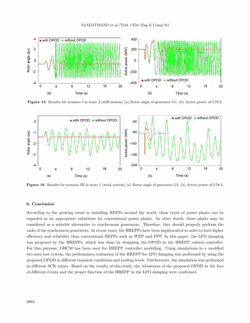
Finally, the simulations are performed for four scenarios in two different states according to Table 4.Figures 14–17 show the results of the simulations for the different SCR values of the system.
Figure 14. Results for scenario I in state 1 (weak system) (a) Rotor angle of generator G1, (b) Active power of L78-2.
As shown in Figures 14–16, the designed OPOD is robust and effective to damp LFO in the weak andstiff systems.
As shown in Figure 17, the voltage oscillations are very intense in the weak system. Moreover, in scenarioIV, the voltage collapses. While the voltage oscillations are eliminated by applying the designed OPOD.
The simulation results show a suitable performance in terms of increasing the oscillation damping andreducing the settling time in the different SCR values. Thus, the designed OPOD has enough robustness forLFO damping.
3863
SAADATMAND et al./Turk J Elec Eng & Comp Sci
Figure 15. Results for scenario I in state 2 (stiff system) (a) Rotor angle of generator G1, (b) Active power of L78-2.
Figure 16. Results for scenario III in state 1 (weak system) (a) Rotor angle of generator G1, (b) Active power of L78-2.
6. Conclusion
According to the growing trend in installing REPPs around the world, these types of power plants can beregarded as an appropriate substitute for conventional power plants. In other words, these plants may beconsidered as a suitable alternative to synchronous generators. Therefore, they should properly perform thetasks of the synchronous generators. In recent years, the HREPPs have been implemented in order to have higherefficiency and reliability than conventional REPPs such as WPP and PPP. In this paper, the LFO dampingwas proposed by the HREPPs, which was done by designing the OPOD in the HREPP central controller.For this purpose, GHCM has been used for HREPP controller modelling. Using simulations in a modifiedtwo-area test system, the performance evaluation of the HREPP for LFO damping was performed by using theproposed OPOD in different transient conditions and loading levels. Furthermore, the simulation was performedin different SCR values. Based on the results of this study, the robustness of the proposed OPOD in the faceof different events and the proper function of the HREPP in the LFO damping were confirmed.
3864
SAADATMAND et al./Turk J Elec Eng & Comp Sci
Figure 17. PCC voltage for state 1 (weak system) (a) scenario I, (b) scenario II, (c) scenario III, (d) scenario IV.
References
[1] Kabalci E. Design and analysis of a hybrid renewable energy plant with solar and wind power. Energy Conversionand Management 2013; 72: 51-59.
[2] Sharma R, Suhag S. Supercapacitor utilization for power smoothening and stability improvement of a hybrid energysystem in a weak grid environment. Turkish Journal of Electrical Engineering & Computer Sciences 2018; 26(1):347-362.
[3] Mueller S, Frankl P, Sadamori K. Next generation wind and solar power from cost to value. Paris, France:International Energy Agency, 2016.
[4] Qi JI, Gangui YA, Yuru CA, Yonglin LI, ZHANG J. Small-signal stability analysis of photovoltaic generationconnected to weak AC grid. Journal of Modern Power Systems and Clean Energy 2018; 1: 1-4.
[5] Pourbeik P, Sanchez-Gasca JJ, Senthil J, Weber JD, Zadehkhost PS et al. Generic dynamic models for modelingwind power plants and other renewable technologies in large-scale power system studies. IEEE Transactions onEnergy Conversion 2017; 32(3): 1108-1116.
[6] Eftekharnejad S, Vittal V, Heydt GT, Keel B, Loehr J. Impact of increased penetration of photovoltaic generationon power systems. IEEE Transactions on Power Systems 2013; 28(2): 893-901.
[7] Shah R, Mithulananthan N, Bansal RC. Oscillatory stability analysis with high penetrations of large-scale photo-voltaic generation. Energy Conversion and Management 2013; 65: 420-429.
[8] Bu SQ, Du W, Wang HF, Chen Z, Xiao LY et al. Probabilistic analysis of small-signal stability of large-scale powersystems as affected by penetration of wind generation. IEEE Transactions on Power Systems 2012; 27(2): 762-770.
3865
SAADATMAND et al./Turk J Elec Eng & Comp Sci
[9] Gautam D, Vittal V, Harbour T. Impact of increased penetration of DFIG-based wind turbine generators ontransient and small signal stability of power systems. IEEE Transactions on Power Systems 2009; 24(3): 1426-1434.
[10] Fan L, Yin H, Miao Z. On active/reactive power modulation of DFIG-based wind generation for interarea oscillationdamping. IEEE Transactions on Energy Conversion 2011; 26(2): 513-521.
[11] Knuppel T, Nielsen JN, Jensen KH, Dixon A, Ostergaard J. Small-signal stability of wind power system withfull-load converter interfaced wind turbines. IET Renewable Power Generation 2012; 6(2): 79-91.
[12] Quintero J, Vittal V, Heydt GT, Zhang H. The impact of increased penetration of converter control-based generatorson power system modes of oscillation. IEEE Transactions on Power Systems 2014; 29(5): 2248-2256.
[13] Shah R, Mithulananthan N, Lee KY. Large-scale PV plant with a robust controller considering power oscillationdamping. IEEE Transactions on Energy Conversion 2013; 28(1): 106-116.
[14] Zhou L, Yu X, Li B, Zheng C, Liu J et al. Damping Inter-Area Oscillations With Large-Scale PV Plant by ModifiedMultiple-Model Adaptive Control Strategy. IEEE Transactions on Sustainable Energy 2017; 8(4): 1629-1636.
[15] Shen Y, Yao W, Wen J, He H. Adaptive wide-area power oscillation damper design for photovoltaic plant consideringdelay compensation. IET Generation, Transmission & Distribution 2017; 11(18): 4511-4519.
[16] Domínguez-García JL, Gomis-Bellmunt O, Bianchi FD, Sumper A. Power oscillation damping supported by windpower: A review. Renewable and Sustainable Energy Reviews 2012; 16(7): 4994-5006.
[17] Singh M, Allen AJ, Muljadi E, Gevorgian V, Zhang Y et al. Interarea oscillation damping controls for wind powerplants. IEEE Transactions on sustainable energy 2015; 6(3): 967-975.
[18] WECC Renewable Energy Modeling Task Force. WECC Solar PV Dynamic Model Specification. Salt Lake City,UT, USA: Western Electricity Coordinating Council, 2012.
[19] Soni S. Solar PV plant model validation for grid integration studies. MSc, Arizona State University, Tempe, AZ,USA, 2014.
[20] WECC Renewable Energy Modeling Task Force. WECC Second Generation Wind Turbine Models. Salt Lake City,UT, USA: Western Electricity Coordinating Council, 2014.
[21] Pourbeik P. Model user guide for generic renewable energy system models. Palo Alto, CA, USA: Electric PowerResearch Institute (EPRI), 2015.
[22] Tan YT. Impact on the power system with a large penetration of photovoltaic generation. PhD, The University ofManchester Institute of Science and Technology, Manchester, UK, 2004.
[23] Panda S, Padhy NP. Comparison of particle swarm optimization and genetic algorithm for FACTS-based controllerdesign. Applied Soft Computing 2008; 8(4):1418-1427.
[24] Shayeghi H, Shayanfar HA, Safari A, Aghmasheh R. A robust PSSs design using PSO in a multi-machine environ-ment. Energy Conversion and Management 2010; 51(4): 696-702.
[25] Almutairi A, Milanovic J. Enhancement of power system stability using wide area measurement system baseddamping controller. PhD, The University of Manchester, Manchester, UK, 2010.
[26] Cai D. Wide area monitoring, protection and control in the future Great Britain power system. PhD, The Universityof Manchester, Manchester, UK, 2012.
[27] Kundur P, Balu NJ, Lauby MG. Power system stability and control. New York, NY, USA: McGraw-Hill, 1994.
[28] Hasanvand H, Arvan MR, Mozafari B, Amraee T. Coordinated design of PSS and TCSC to mitigate interareaoscillations. International Journal of Electrical Power & Energy Systems 2016; 78: 194-206.
[29] Kerahroudi SK, Alamuti MM, Li F, Taylor GA, Bradley ME. Application and requirement of DIgSILENT Power-Factory to MATLAB/Simulink interface. In: Gonzalez-Longatt FM, Rueda JL (editors). Powerfactory Applicationsfor Power System Analysis. Cham, Switzerland: Springer, 2014, pp. 297-322.
[30] Kennedy J, Eberhart RC, Shi Y. Swarm Intelligence. San Francisco, CA, USA: Morgan Kaufmann Publishers, 2001.
3866
SAADATMAND et al./Turk J Elec Eng & Comp Sci
[31] Nguyen TT, Gianto R. Optimisation-based control coordination of PSSs and FACTS devices for optimal oscillationsdamping in multi-machine power system. IET Generation, Transmission & Distribution 2007; 1(4): 564-573.
[32] Das TK, Venayagamoorthy GK, Aliyu UO. Bio-inspired algorithms for the design of multiple optimal power systemstabilizers: SPPSO and BFA. IEEE Transactions on Industry Applications 2008; 44(5): 1445-1457.
[33] Shayeghi H, Shayanfar HA, Jalili A. Multi-stage fuzzy PID power system automatic generation controller inderegulated environments. Energy Conversion and management 2006; 47(18-19): 2829-2845.
[34] Zhang Y, Huang SH, Schmall J, Conto J, Billo J et al. Evaluating system strength for large-scale wind plantintegration. IEEE PES General Meeting|Conference & Exposition; National Harbor, MD, USA; 2014. pp. 1-5.
[35] Wu D, Javadi M, Ma F, Tan J, Jiang JN. A method to identify weak points of interconnection of renewable energyresources. International Journal of Electrical Power & Energy Systems 2019; 110:72-82.