Damping of power system oscillations with unified power flow controller (UPFC) N. Tambey and M.L. Kothari Abstract: A comprehensive approach to the design of UPFC controllers (power-flow controller, DC-voltage regulator and damping controller) is presented. Studies reveal that damping is adversely affected by the incorporation of a DC-voltage regulator. Investigations were carried out to understand the relative effectiveness of modulation of thc UPFC control signals in R , S B , ni E and <5 £ on damping of the system oscillations, using a controllability index. A dual damping controller based on simultaneous modulation of UPFC control signals in B and b E is proposed. Investigations reveal that altemative damping controllers (damping controller in B , damping controller S E and dual damping controller) provide robust dynamic performance under wide variations in loading condition and system parameters. List of symbols H inertia constant (M = 2 H) w n natural frequency of oscillation. rad s-' X e equivalent rcactance of the system X T reactance of transmission line 1 X Bu reactance of transmission line 2 X, E reactance of transformer X E rcactance of excitation transformer (ET) X a reactance of boosting transfonner (BT) X (i direct axis Steady-state synchronous reactance of the generator X q quadrature axis steady-state synchronous reac tance of the generator X' d direct axis transient synchronous reactance of the generator T^ direct axis open-circuit time-constant of the generator P c electrical power of the generator P m mechanical power input to the generator P.Z~,~~ reference power on transmission line 2 Pennflm modified reference power on transmission line 2 V, generator tenninal voltage V,, infinite bus voltage V, voltage at UPFC bus V Bo initial value of series-injected voltage V E , initial value of shunt-injected voltage I,] current through transmission line 1 I R current through transmission line 2 I E current through shunt converter V dc voltage at DC link Q/ c DC link capacitor m E modulation index of shunt converter m a modulation index of series converter KDC ga in of damping controller T,,T 2 time constants of phase compensator SEE Proceedings online no, 20030114 iioi:IO.I049/ip-gld:200301I4 Paper received 23rd July 2002 The authors are with the Department of Electrical Engineering. Indian Institute of Technology, Hauz Khas. New Delhi 110 016, India J E phase angle of shunt-converter voltage (T B phase angle of series-converter voltage 1 Introduction The power transfer in an integrated power system is constrained by transient stability, voltage stability and small-sign1 stability. These constraints limit the full utilisation of the available transmission corridors. The flexible AC transmission system (FACTS) is the technology that provides the corrections to the transmission function- ality required in order to fully utilise the existing transmis- sion facilities, hence minimising the gap between the stability and thennal-loading limits. The unified power flow controller (UPFC) is a FACTS device which can control power-system parameters such as tenninal voltage, line impedance and phase angle [1-3]. The primary function of the UPFC is to control power flow on a given line and voltage at the UPFC bus. This is achieved by regulating the controllable parameters of the system: line impedance. phase angle and voltage magnitude. The UPFC can also be utilised for damping power-system oscillations by judiciously applying a damping controller. Unlike the PSS at a generator location. the speed deviations of the machines of interest are not readily available to a FACTS controller located on a transmission path. For a UPFC- based damping controller, we wish to extract an input signal to the damping controller from the locally measurable quantities at the UPFC location. The elcctrical power flow can be easily measured at the UPFC location and hencc may be used as an input signal to the damping controller. Recently, steady-state and dynamic models of UPFC have been developed by several researchers [&8]. Wang [9- I I ] has developed modified linearised Heffroni-Phillips models for an SMIB system and a multi-machine system with UPFC installed. He has proposed criteria for, the selection of operating condition and control signal in order to design a robust UPFC-based damping controller. For a multi-machine system, he has proposed a controllability- index approach to selecting the control signal. He has also considered proportional-type power-flow controllers, AC- voltage and DC-voltage regulators and also damping SEE Proc.-Gentr. Trmam. Distrib., Vol. 150, No. 2, March 2003 I29
Transcript
Damping of power system oscillations with unified power flow controller (UPFC)
N. Tambey and M.L. Kothari
Abstract: A comprehensive approach to the design of UPFC controllers (power-flow controller, DC-voltage regulator and damping controller) is presented. Studies reveal that damping is adversely affected by the incorporation of a DC-voltage regulator. Investigations were carried out to understand the relative effectiveness of modulation of thc UPFC control signals inR, SB, niE and <5£ on damping of the system oscillations, using a controllability index. A dual damping controller based on simultaneous modulation of UPFC control signals inB and bE is proposed. Investigations reveal that altemative damping controllers (damping controller inB, damping controller SE and dual damping controller) provide robust dynamic performance under wide variations in loading condition and system parameters.
List of symbols
H inertia constant (M = 2 H) wn natural frequency of oscillation. rad s-' Xe equivalent rcactance of the system XT reactance of transmission line 1 XBu reactance of transmission line 2 X,E reactance of transformer XE rcactance of excitation transformer (ET) X a reactance of boosting transfonner (BT) X(i direct axis Steady-state synchronous reactance of
the generator Xq quadrature axis steady-state synchronous reac
tance of the generator X'd direct axis transient synchronous reactance of the
generator T^ direct axis open-circuit time-constant of the
generator Pc electrical power of the generator Pm mechanical power input to the generator P.Z~,~~ reference power on transmission line 2 Pennflm modified reference power on transmission line 2 V, generator tenninal voltage V,, infinite bus voltage V, voltage at UPFC bus VBo initial value of series-injected voltage VE, initial value of shunt-injected voltage I,] current through transmission line 1 IR current through transmission line 2 IE current through shunt converter Vdc voltage at DC link Q/c DC link capacitor mE modulation index of shunt converter ma modulation index of series converter KDC gain of damping controller T,,T2 time constants of phase compensator
SEE Proceedings online no, 20030114 iioi:IO.I049/ip-gld:200301I4 Paper received 23rd July 2002 The authors are with the Department of Electrical Engineering. Indian Institute of Technology, Hauz Khas. New Delhi 110 016, India
JE phase angle of shunt-converter voltage (TB phase angle of series-converter voltage
1 Introduction
The power transfer in an integrated power system is constrained by transient stability, voltage stability and small-sign1 stability. These constraints limit the full utilisation of the available transmission corridors. The flexible AC transmission system (FACTS) is the technology that provides the corrections to the transmission function-ality required in order to fully utilise the existing transmis-sion facilities, hence minimising the gap between the stability and thennal-loading limits.
The unified power flow controller (UPFC) is a FACTS device which can control power-system parameters such as tenninal voltage, line impedance and phase angle [1-3]. The primary function of the UPFC is to control power flow on a given line and voltage at the UPFC bus. This is achieved by regulating the controllable parameters of the system: line impedance. phase angle and voltage magnitude. The UPFC can also be utilised for damping power-system oscillations by judiciously applying a damping controller. Unlike the PSS at a generator location. the speed deviations of the machines of interest are not readily available to a FACTS controller located on a transmission path. For a UPFC-based damping controller, we wish to extract an input signal to the damping controller from the locally measurable quantities at the UPFC location. The elcctrical power flow can be easily measured at the UPFC location and hencc may be used as an input signal to the damping controller.
Recently, steady-state and dynamic models of UPFC have been developed by several researchers [&8]. Wang [9-I I ] has developed modified linearised Heffroni-Phillips models for an SMIB system and a multi-machine system with UPFC installed. He has proposed criteria for, the selection of operating condition and control signal in order to design a robust UPFC-based damping controller. For a multi-machine system, he has proposed a controllability-index approach to selecting the control signal. He has also considered proportional-type power-flow controllers, AC-voltage and DC-voltage regulators and also damping
SEE Proc.-Gentr. Trmam. Distrib., Vol. 150, No. 2, March 2003 I29
controllers. 'However, he has not presented a comprehensive approach to obtaining optimum parameters for the power-flow controller and DC-Voltage regulator. Padiyar and Kulkami [I21 have proposed a UPFC control strategy based on lokal measurements, in which real power flow through the line is controlled by reactive vohge injection and reactive power flow is controlled by regula.ting the magnitude of voltages at the two UPFC ports. They have also included an auxiliary controller for improving the transient stability of the system. However, they have not presented an approach for obtaining the optimum para-meters of the power-flow and auxiliary controllers. In view or the above, the main objectives of the research work presented here are as follows. Firstly, to present a comprehensive approach to designing power-flow and DC-voltage UPFC regulators. Secondly, to deign and study the performance of the UPFC-based ,&ing controllers taking into account alternative UPFC: control parameters. Lastly, to investigate the performance of altemative damping controllers under wide variations in loading condition and in system parameters.
2 System investigated
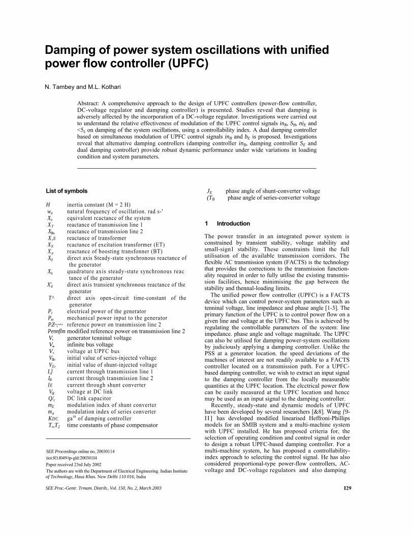
We consider a single machine infinite bus (SMIB) system with UPFC installed [13]. The UPFC is installed in one of the two parallel transmission lines (Fig. I). This configura-tion, comprising two parallel transmission lines, permits the control of real and reactive power flow through a line. The static excitation system, model type IEEE-STIA, has been considered. The UPFC is assumed to he based ,on pulse
UPFC may also provide an independent, controllable, shunt reactive compensation.
4 Dynamic model of the system with UPFC
4.7 Non-linear dynamic model A non-linear dynamic model of the system is derived by disregarding the resistances of all the components of the system (generator, transfomier, transmission lines, shunt and series converter transformers) and the transients of the transmission lines and transformers of the UPFC. The non-linear dynamic model of the system using UPFC is given below:
M (1)
8 = a)0(a) - 1) (2)
F' (-Eq + Erd) 4 T'do
(3)
fi t + Ka{ Vmf — Ta
'te = —— (sin(5j5)/£y + cos(<5e)/£?)
' 3/"tf-(sin((5B)/arf + cos(^)/fl?) (5)
where V/d =XqItq\ V,q — Eq —Xdllti; hd =h\d + hd + lBd\ Jig = l/\q + hjj + hq\
I,u =^ /a, + ±- ^ cos(fc) -±- Aj Aj L A f
Vh sin(S); A
IEd ^
XJTtns
Fig. 1 A Single muchine infinirc bus (SMIB) poww. syslem inslulled with an UPFC in ow of rhr lines „ ■ ,»
(x "b sin(dj
+ XBBXal)
width modulation (PWM) converters. The conventional PSS is considered. The nominal loading condition and system parameters are even in Appendix 1.
(xb l - COS(<5£
3 Unified power flow controller
The unified power flow controller (UPFC) was devised for the real-time control and dynamic compensation of AC transmission systems, providing the multifunctional flex-ibility required to solve many of the problems facing the power-supply industry. The UPFC is a combination of a static synchronous compensator (STATCOM) and a static synchronous series compensator (SSSC) coupled via a common DC voltage link. It is capable of controlling. simultaneously or selectively, all the parameters affecting the power flow in a transmission line (voltage, impedance and phase angle). Alternatively, it can control both the real and the reactive power flow in the line independently. The
The equation for the real power balance between the series and shunt converters is given as
Re(V& - &I;) = 0 (6)
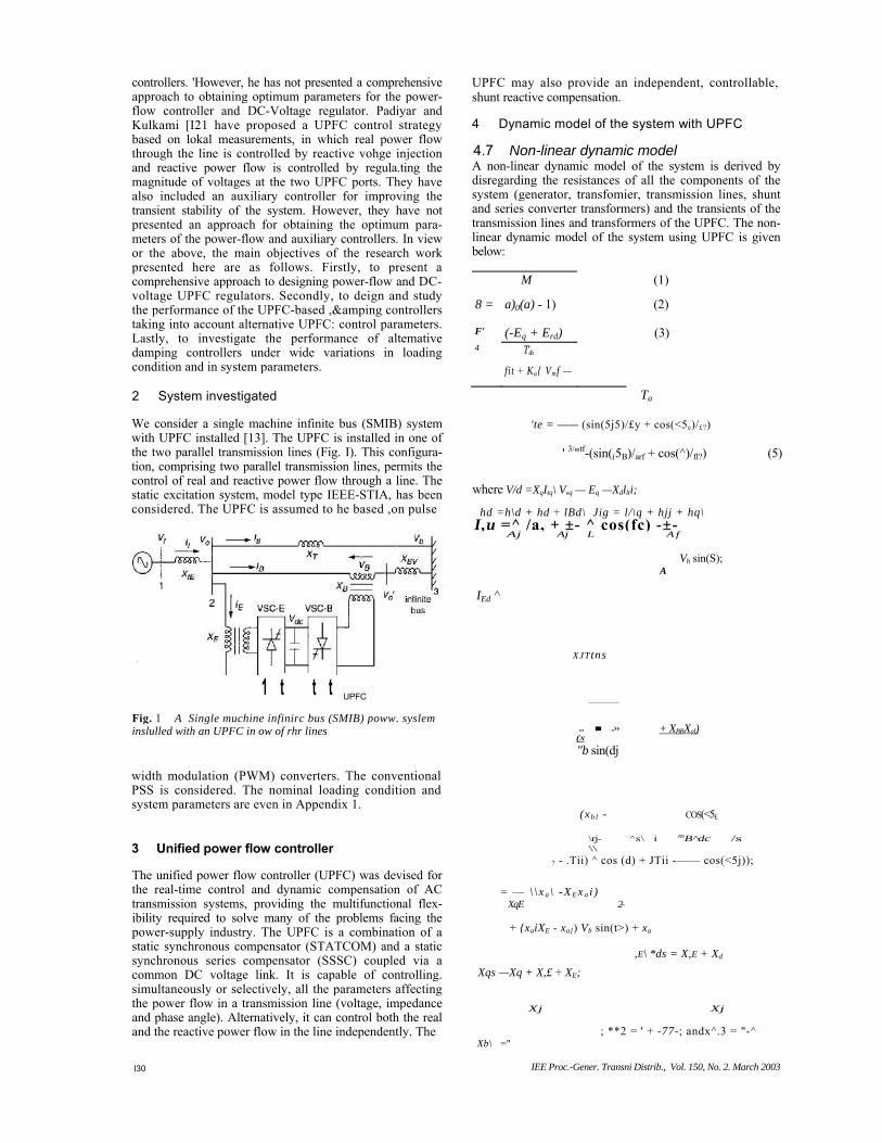
4.2 Linear dynamic model (modified Heffron-Phillips model of an SMlB system including UPFC) A linear dynamic model is obtained by linearising the non-linear model around an operating condition. The linedrised model is given below:
A . (AP, - AP, - D
AW =------------- M ~
AS = a>0Aa>
constants in the Heffron-Phillips model. These constants are functions of the system parameters and the initid operating condition. The equations for computing the constants of the model are given in Appendix 2. The control vector u is defined as follows:
('2)
where AmB
deviation in pulse width modulation index mg of series inverter. By controlling mB, the magnitude
of series-injected voltage can be contiolled. deviation in phase angle of the injected voltage deviation in pulse-
width-modulation index m~ of the shunt inverter. By controlling inB the output voltage of the shunt
converter is controlled, deviation in phase angle of the shunt-inverter voltage. The series and shunt converters are controlled in a coordinated manner
to ensure that the real power output of the shunt converter is equal to the real power input to the series converter. The fact that the DC voltage remains constant ensures that this equality is maintained.
It may be noted that ICpu, Kqu, K, and K, in Fig. 2 are the row vectors defined below:
where K poe Kpc%\
K-q
AEq =K4AS + K3AEb+
+ KqfeA&E + KqbAmB A V, =KsA6 + KhAE; + K,AmE+
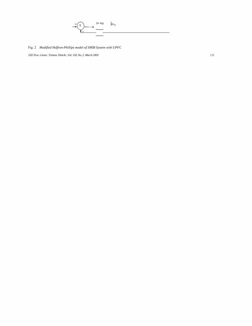
Fig. 2 shows the modified Heffron-Phillips transfer-function model of the system including UPFC. The modified Heffron-Phillips model has 28 constants as opposed to 6
where u = [AmE A5E AmB AABIR is a column vector.
4.3 Dynamic model in state-space form The dynamic model of the system in state-space form is obtained from the transfer-function model as
X = AX + Bu
'"0 A6
^pu K-i+STl, *qu «<7rf «4
ka 1
+ STa
«5
(8) (9)
(10)
^ - KgAKt + K^AniE
K~SE + K,bAmtr + Kc&A6~ (11)
{-AEq
Atfd =
AdB
Ad,
; and +
(13)
MS+D
S+ Kg iVdc
Fig. 2 Modified Heffron-Phillips model of SMIB System with UPFC
1EE Proc.-Gener. Trtmsm. Distrib., Vol. 150, No, 2. March 2003 131
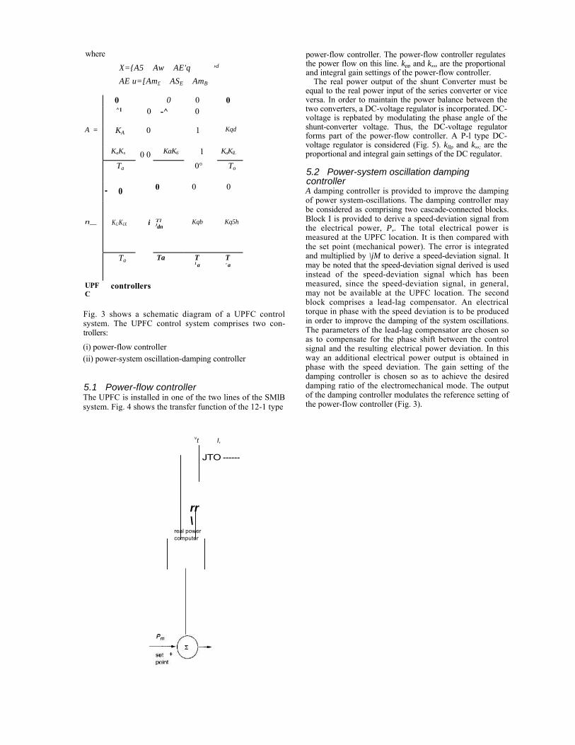
where X={A5 Aw AE'q AE u=[Am£ ASE AmB
0 0 0 0 ^1 0 -^ 0
A = KA 0 1 Kqd
KaKs KaK6 1 KaKlL
Ta 0 0
0° To
- o 0 0 0
n__ KUKIX i Tl
Jdn Kqb Kq5h
Ta Ta T 1 a
T ' a
UPFC
controllers
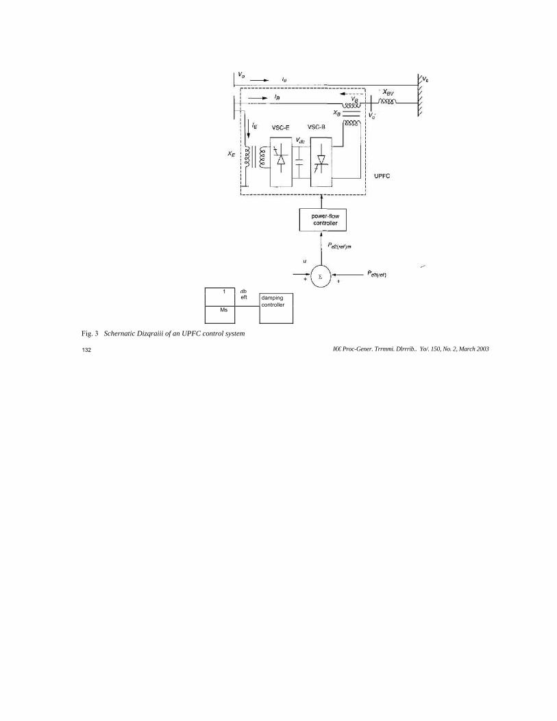
Fig. 3 shows a schematic diagram of a UPFC control system. The UPFC control system comprises two con-trollers: (i) power-flow controller (ii) power-system oscillation-damping controller
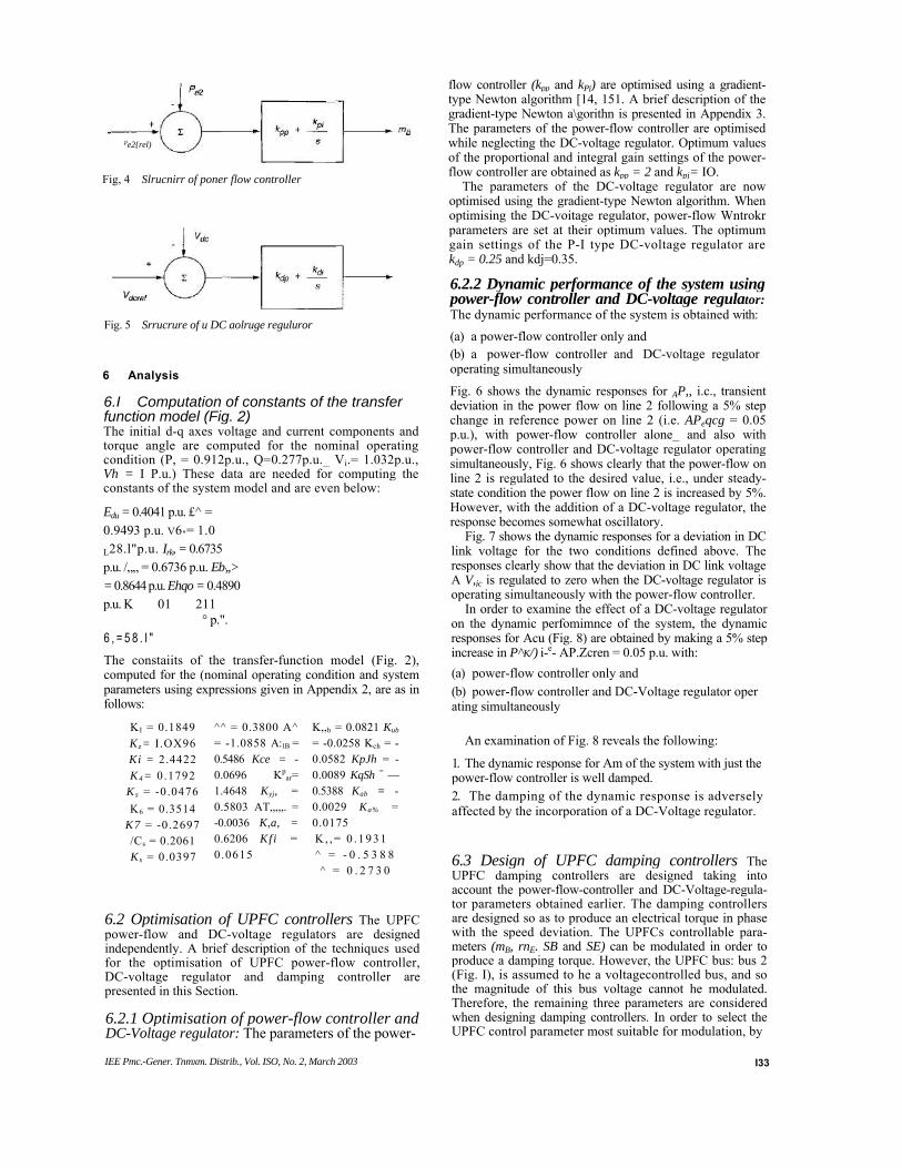
5.1 Power-flow controller The UPFC is installed in one of the two lines of the SMlB system. Fig. 4 shows the transfer function of the 12-1 type
power-flow controller. The power-flow controller regulates the power flow on this line. kpp and k,,, are the proportional and integral gain settings of the power-flow controller.
The real power output of the shunt Converter must be equal to the real power input of the series converter or vice versa. In order to maintain the power balance between the two converters, a DC-voltage regulator is incorporated. DC-voltage is repbated by modulating the phase angle of the shunt-converter voltage. Thus, the DC-voltage regulator forms part of the power-flow controller. A P-l type DC-voltage regulator is considered (Fig. 5). kllp and k,,; are the proportional and integral gain settings of the DC regulator.
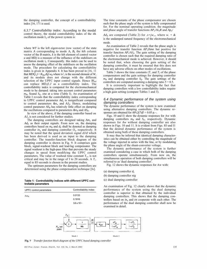
5.2 Power-system oscillation damping controller A damping controller is provided to improve the damping of power system-oscillations. The damping controller may be considered as comprising two cascade-connected blocks. Block I is provided to derive a speed-deviation signal from the electrical power, P,. The total electrical power is measured at the UPFC location. It is then compared with the set point (mechanical power). The error is integrated and multiplied by \jM to derive a speed-deviation signal. It may be noted that the speed-deviation signal derived is used instead of the speed-deviation signal which has been measured, since the speed-deviation signal, in general, may not be available at the UPFC location. The second block comprises a lead-lag compensator. An electrical torque in phase with the speed deviation is to be produced in order to improve the damping of the system oscillations. The parameters of the lead-lag compensator are chosen so as to compensate for the phase shift between the control signal and the resulting electrical power deviation. In this way an additional electrical power output is obtained in phase with the speed deviation. The gain setting of the damping controller is chosen so as to achieve the desired damping ratio of the electromechanical mode. The output of the damping controller modulates the reference setting of the power-flow controller (Fig. 3).
,d
vt I,
JTO ------
rr\
real power computer
db1 eft
Ms
damping controller
Fig. 3 Schernatic Dizqraiii of an UPFC control system
6.I Computation of constants of the transfer function model (Fig. 2) The initial d-q axes voltage and current components and torque angle are computed for the nominal operating condition (P, = 0.912p.u., Q=0.277p.u._ Vi.= 1.032p.u., Vh = I P.u.) These data are needed for computing the constants of the system model and are even below: Edu = 0.4041 p.u. £^ = 0.9493 p.u. V6"= 1.0
° p.". 6 , = 5 8 . I " The constaiits of the transfer-function model (Fig. 2), computed for the (nominal operating condition and system parameters using expressions given in Appendix 2, are as in follows:
flow controller (kpp and kPj) are optimised using a gradient-type Newton algorithm [14, 151. A brief description of the gradient-type Newton a\gorithn is presented in Appendix 3. The parameters of the power-flow controller are optimised while neglecting the DC-voltage regulator. Optimum values of the proportional and integral gain settings of the power-flow controller are obtained as kpp = 2 and kpj= IO.
The parameters of the DC-voltage regulator are now optimised using the gradient-type Newton algorithm. When optimising the DC-voitage regulator, power-flow Wntrokr parameters are set at their optimum values. The optimum gain settings of the P-I type DC-voltage regulator are kdp = 0.25 and kdj=0.35.
6.2.2 Dynamic performance of the system using power-flow controller and DC-voltage regulator: The dynamic performance of the system is obtained with: (a) a power-flow controller only and (b) a power-flow controller and DC-voltage regulator operating simultaneously
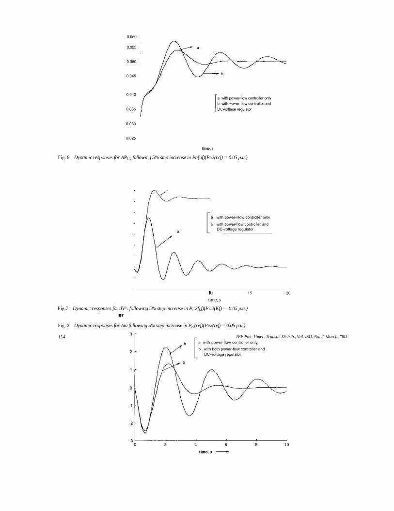
Fig. 6 shows the dynamic responses for AP,, i.c., transient deviation in the power flow on line 2 following a 5% step change in reference power on line 2 (i.e. APeqcg = 0.05 p.u.), with power-flow controller alone_ and also with power-flow controller and DC-voltage regulator operating simultaneously, Fig. 6 shows clearly that the power-flow on line 2 is regulated to the desired value, i.e., under steady-state condition the power flow on line 2 is increased by 5%. However, with the addition of a DC-voltage regulator, the response becomes somewhat oscillatory.
Fig. 7 shows the dynamic responses for a deviation in DC link voltage for the two conditions defined above. The responses clearly show that the deviation in DC link voltage A V,jc is regulated to zero when the DC-voltage regulator is operating simultaneously with the power-flow controller.
In order to examine the effect of a DC-voltage regulator on the dynamic perfomimnce of the system, the dynamic responses for Acu (Fig. 8) are obtained by making a 5% step increase in P^K/) i-e- AP.Zcren = 0.05 p.u. with: (a) power-flow controller only and (b) power-flow controller and DC-Voltage regulator oper ating simultaneously
An examination of Fig. 8 reveals the following: 1. The dynamic response for Am of the system with just the power-flow controller is well damped. 2. The damping of the dynamic response is adversely affected by the incorporation of a DC-Voltage regulator.
6.3 Design of UPFC damping controllers The UPFC damping controllers are designed taking into account the power-flow-controller and DC-Voltage-regula-tor parameters obtained earlier. The damping controllers are designed so as to produce an electrical torque in phase with the speed deviation. The UPFCs controllable para-meters (mB, rnE. SB and SE) can be modulated in order to produce a damping torque. However, the UPFC bus: bus 2 (Fig. I), is assumed to he a voltagecontrolled bus, and so the magnitude of this bus voltage cannot he modulated. Therefore, the remaining three parameters are considered when designing damping controllers. In order to select the UPFC control parameter most suitable for modulation, by
6.2 Optimisation of UPFC controllers The UPFC power-flow and DC-voltage regulators are designed independently. A brief description of the techniques used for the optimisation of UPFC power-flow controller, DC-voltage regulator and damping controller are presented in this Section.
6.2.1 Optimisation of power-flow controller and DC-Voltage regulator: The parameters of the power-
0.060 0.055
0.050
0.045
0.040
0.035
0.030
0.025 time, s
Fig. 6 Dynamic responses for APL,2 following 5% step increase in Pa(nf)(Pe2(rcj) = 0.05 p.u.)
10 time, s
15 20
Fig.7 Dynamic responses for dV^. following 5% step increase in P,:2fKf)(Pi:2(Kf) — 0.05 p.u.) ■r
Fig. 8 Dynamic responses for Am following 5% step increase in Pc2(ref)(Pe2(refj = 0.05 p.u.)
a with power-flow controller only b with ~o~er-tlow controllei and DC-voltage regulator
a with power-How controller only
b with power-flow controller and DC-voltage regulator
a with power-flow controller only
b with both power-flow controller and DC-voltage regulator
the damping controller, the concept of a controlbahility index [16, 171 is used.
6.3.7 Controllability index: According to the modal control theory, the modal controllability index of the ith oscillation mode Lj of the power system is:
where WT is the left eigenvector (row vector) of the state matrix A corresponding to mode Aj Bk the kth column vector of the B matrix, k is the kth element of control vector u and MDj is a measure of the influence of the stahilisers on oscillation mode ii. Consequently. this index can be used to assess the damping effect of the stahilisers on the oscillation mode. The procedure for calculating the controllability index is given in Appendix 4. It has been proved in [16, 11 that MDQ.,) = Khk,(Aj) wB where H-'C is the second element of W, and its module does not change with the different selection of the UPFC input control signals. Hence lKhtl can replace MD,(l.J as a controllability index. The controllability index is computed for the electromechanical mode to he damped. taking into account control parameters mR, Soand SE, one at a time (Table I). An examination of Table I rcveals that the controllability index corresponding to UPFC control parameter Ado is insignificant compared to control parameters &no and AJE. Hence, modulating control parameter ASB has relatively little effect on damping the oscillations compared to parameters &nB and ASE.
In vicw of the above, if the damping controller based on AJo is not considered for further studies.
The damping controllers are designed taking Amo and AdE as their output signals. From now on, the damping controllers based on mB and dE shall be denoted as damping controller ing and damping controller Os, respectively. It may be noted that the speed deviatioii signal dJ/d which has been derived is used as an input to the damping controller. The transfer-function block diagram of the damping controller is shown in Fig. 9. It comprises gain block, signal-washout block and lead-lag compensator. The signal washout is the high-pass filter that prevents the steady changes in speed from modifying the UPFC control parameters. The value of washout time constant T,,, is not critical and may be in the range of I to 20 seconds. A T,. equal to IO seconds is chosen in the present studies.
The optimum parameters for the damping controllers are determined using the phase compensation technique [Is].
Table 1: Controllability indices with different UPFC con-trollable parameters
UPFC control parameters
AmB
The time constants of the phase compensator are chosen such that the phase angle of the system is fully compensated for. For the nominal operating condition. the magnitude and phase angle of transfer functions APe/AinR and Ape/ AdE are computed (Table 2) for .s=jw,,, where w. = & is the undamped natural frequency of the electromechanical mode.
An examination of Table 2 reveals that the phase angle is negative for transfer function AP,lAme but positive for transfer function AP,/AJE. The gain setting of the damping controller is chosen such that the required damping ratio of the electromechanical mode is achieved. However, it should be noted that, when choosing the gain setting of the damping controller, it must he ensured that this does not have any adverse effects on other modes of oscillations.
Table 3 shows the time constants (T, and TJ of the phase compensators and the gain settings for damping controller mB and damping controller SE. The gain settings of the controllers are computed assuming a damping ratio 5 = 0.5.
It is extremely important to highlight the fact that damping controllers with a low controllability index require a high gain setting (compare Tables 1 and 3).
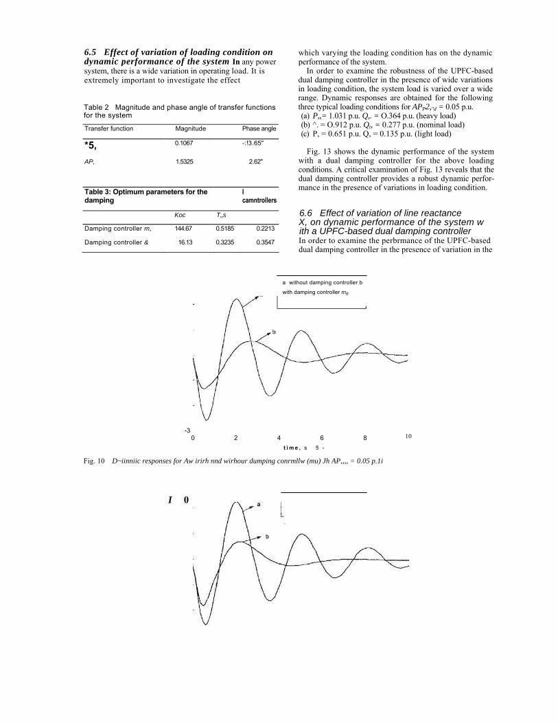
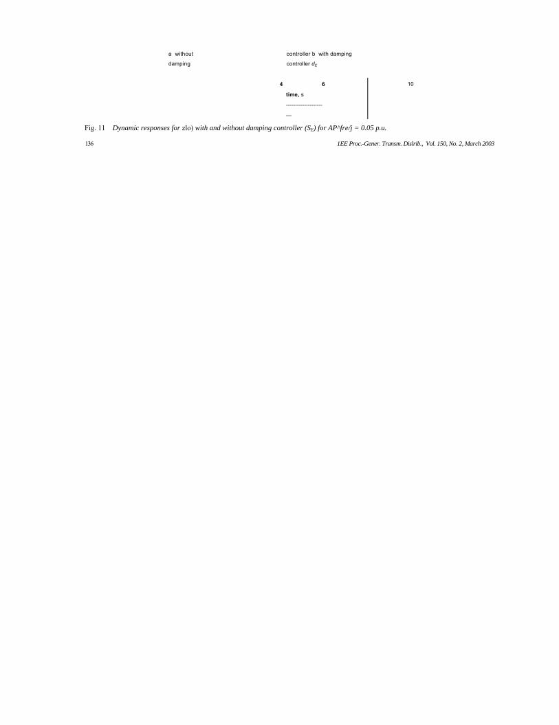
6.4 Dynamic performance of the system using damping controllers The dynamic performance of the system is now examined using alternative damping controllers. The dynamic re-sponses are obtained for APc2(7sfl = 0.05 p.~.
Figs. 10 and I1 show the dynamic responses for Aw with damping controllers mR and SE, respectively. Dynamic responses for Aw without damping controller are also shown in Figs. 10 and 11. It is evident from Figs. IO and I1 that the desired dynamic performance of the system is obtained using both of these damping controllers.
It may thus be inferred that identical damping character-istics can be obtained either by controlling the magnitude of the voltage injected in series with the line, or by modulating the phase angle of the shunt-converter voltage.
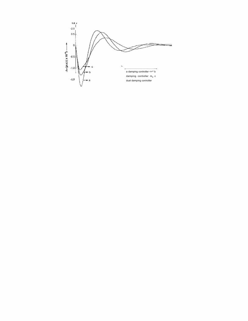
The dynamic performance of the system is further examined considering a case in which both of the damping controllers operate simultaneously. From now on, the simultaneous operation of both damping controllers will be referred to as 'dual damping controller'.
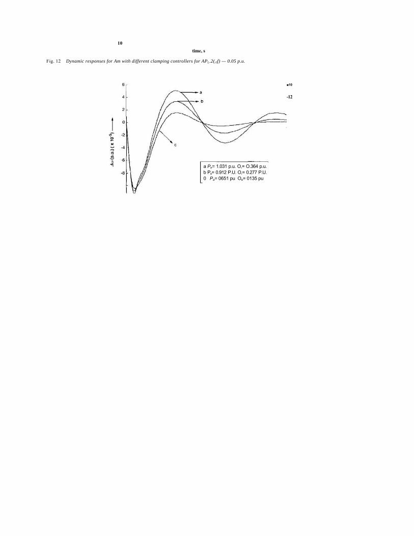
An examination of Fig. 12 clearly shows that the dynamic performance of the system using the dual damping controller is superior to that obtained by the individual damping controllers. This shows that the damping con-trollers based on ing and DE cooperate with each other. The performance of the dual damping controller shall now he examined in detail.
block 1 block 2 Fig. 9 Transfer function block diagram of the UPFC bused damping controller
6.5 Effect of variation of loading condition on dynamic performance of the system In any power system, there is a wide variation in operating load. It is extremely important to investigate the effect
Table 2 Magnitude and phase angle of transfer functions for the system
which varying the loading condition has on the dynamic performance of the system.
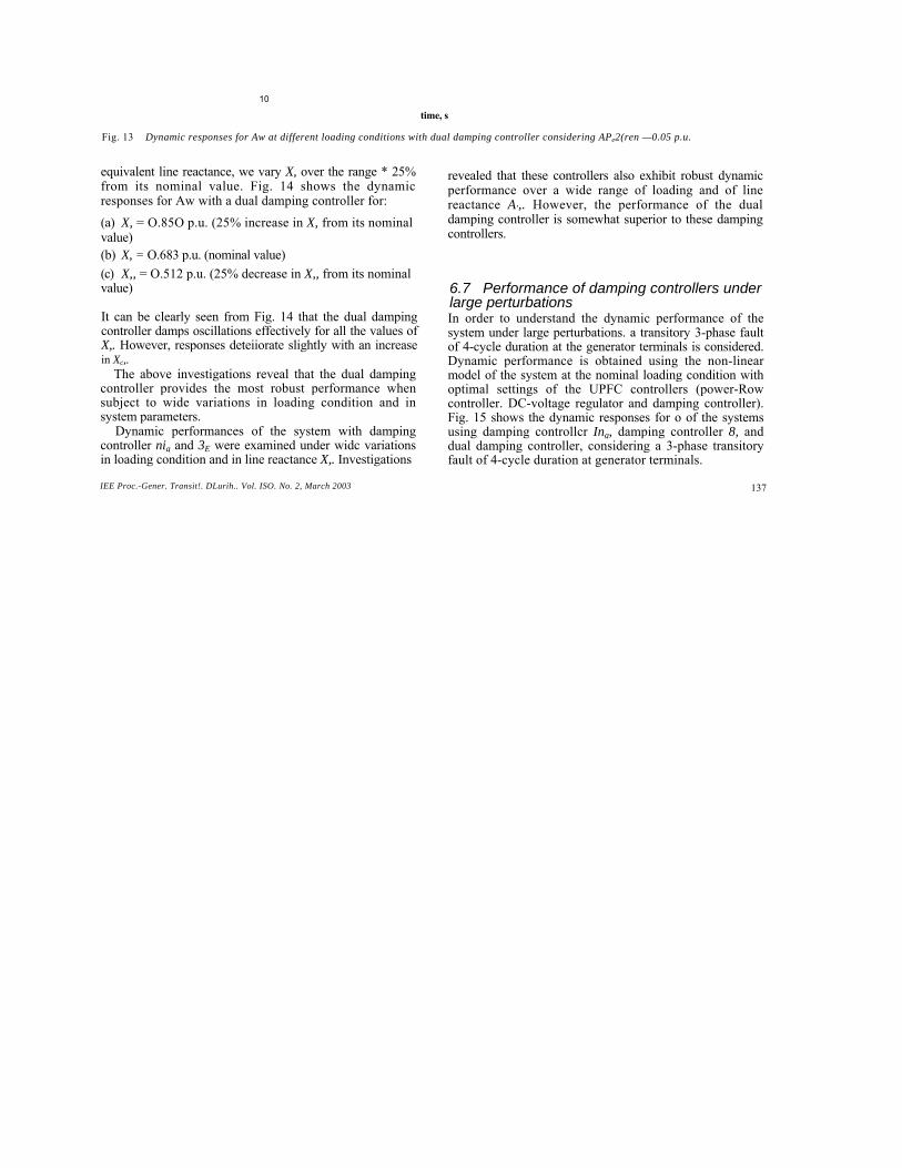
In order to examine the robustness of the UPFC-based dual damping controller in the presence of wide variations in loading condition, the system load is varied over a wide range. Dynamic responses are obtained for the following three typical loading conditions for APP2,"d = 0.05 p.u. (a) P,,= 1.031 p.u. Q,. = O.364 p.u. (heavy load) (b) ^. = O.912 p.u. Qt, = 0.277 p.u. (nominal load) (c) P, = 0.651 p.u. Q, = 0.135 p.u. (light load)
Fig. 13 shows the dynamic performance of the system with a dual damping controller for the above loading conditions. A critical examination of Fig. 13 reveals that the dual damping controller provides a robust dynamic perfor-mance in the presence of variations in loading condition.
6.6 Effect of variation of line reactance X, on dynamic performance of the system w ith a UPFC-based dual damping controller In order to examine the perbrmance of the UPFC-based dual damping controller in the presence of variation in the
a without damping controller b
with damping controller mB
-3
0 2 4 6 8 t i m e , s 5 -
Fig. 10 D~iinniic responses for Aw irirh nnd wirhour dumping conrmllw (mu) Jh AP,,,, = 0.05 p.1i
10
I 0
a without
damping
controller b with damping
controller dE
4 6
time, s
--------------------
—
10
Fig. 11 Dynamic responses for zlo) with and without damping controller (SE) for AP^fre/j = 0.05 p.u.
Fig. 12 Dynamic responses for Am with different clamping controllers for APL.2(rlf) — 0.05 p.u.
■10
-12
a Pe= 1.031 p.u. O,= O.364 p.u. b Ps= 0.912 P.U. O,= 0.277 P.U. 0 Pa= 0651 pu Oe= 0135 pu
10 time, s
Fig. 13 Dynamic responses for Aw at different loading conditions with dual damping controller considering APe2(ren —0.05 p.u.
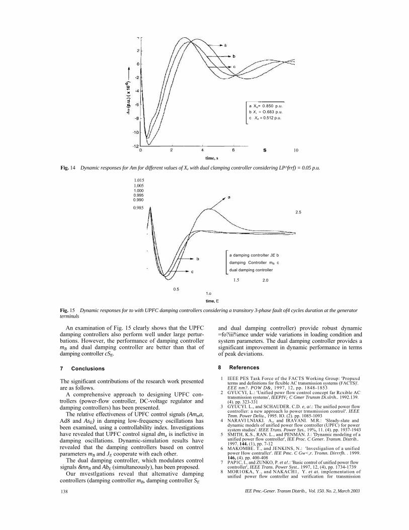
equivalent line reactance, we vary X, over the range * 25% from its nominal value. Fig. 14 shows the dynamic responses for Aw with a dual damping controller for: (a) X, = O.85O p.u. (25% increase in X, from its nominal value) (b) X, = O.683 p.u. (nominal value) (c) X,, = O.512 p.u. (25% decrease in X,, from its nominal value)
It can be clearly seen from Fig. 14 that the dual damping controller damps oscillations effectively for all the values of X,. However, responses deteiiorate slightly with an increase in Xc,.
The above investigations reveal that the dual damping controller provides the most robust performance when subject to wide variations in loading condition and in system parameters.
Dynamic performances of the system with damping controller nig and 3E were examined under widc variations in loading condition and in line reactance X,. Investigations
revealed that these controllers also exhibit robust dynamic performance over a wide range of loading and of line reactance A',. However, the performance of the dual damping controller is somewhat superior to these damping controllers.
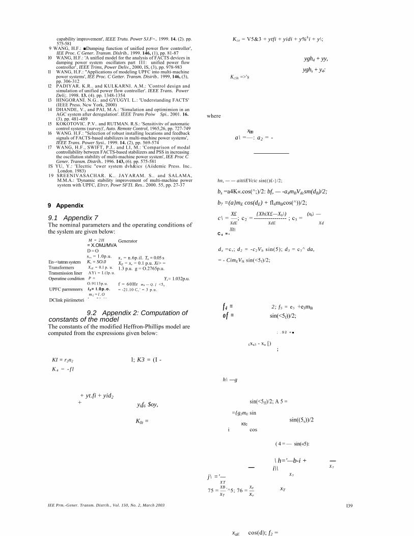
6.7 Performance of damping controllers under large perturbations In order to understand the dynamic performance of the system under large perturbations. a transitory 3-phase fault of 4-cycle duration at the generator terminals is considered. Dynamic performance is obtained using the non-linear model of the system at the nominal loading condition with optimal settings of the UPFC controllers (power-Row controller. DC-voltage regulator and damping controller). Fig. 15 shows the dynamic responses for o of the systems using damping controllcr Ing, damping controller 8, and dual damping controller, considering a 3-phase transitory fault of 4-cycle duration at generator terminals.
time, s Fig. 14 Dynamic responses for Am for different values of Xe with dual clamping controller considering LP^frrf) = 0.05 p.u.
1.015 1.005 1.000 0.995 0.990 0.985
0.5 1.o
time, E
1.5 2.0
2.5
Fig. 15 Dynamic responses for to with UPFC damping controllers considering a transitory 3-phase fault of4 cycles duration at the generator terminuls
An examination of Fig. 15 clearly shows that the UPFC damping controllers also perform well under large pertur-bations. However, the performance of damping controller mB and dual damping controller are better than that of damping controller cSE.
7 Conclusions
The significant contributions of the research work presented are as follows.
A comprehensive approach to designing UPFC con-trollers (power-flow controller, DC-voltage regulator and damping controllers) has been presented.
The relative effectiveness of UPFC control signals (Amma, Ad8 and AsE) in damping low-frequency oscillations has been examined, using a controllability index. Investigations have revealed that UPFC control signal dma is inefictive in damping oscillations. Dynamic-simulation results have revealed that the damping controllers based on control parameters mB and JE cooperate with each other.
The dual damping controller, which modulates control signals &nnB and AbE (simultaneously), has been proposed.
Our mvestlgations reveal that altemative damping controllers (damping controller mB, damping controller SE
and dual damping controller) provide robust dynamic =fo?iii%mce under wide variations in loading condition and system parameters. The dual damping controller provides a significant improvement in dynamic performance in terms of peak deviations.
8 References 1 IEEE PES Task Force of the FACTS Working Group: 'Propuxd
terms and definitions for flcxible AC transmission systems (FACTS)'. EEE nm?. POW D&, 1997, 12, pp. 1848-1853
2 GYUCYI, L.: 'Unified powr flow control concept far Rcxible AC transmission systems', IEEPIVC C Gmer Trunsm Di.slrih.. 1992.139. (4). pp. 323-331
3 GYUCYI. L., and SCHAUDER. C.D. e, a/.: The unified power flow controller: a new approach lo power trmsmission control'. IEEE Tmm. Power Deliu., 1995. IO. (2). pp. 1085-1093
4 NARAVI LNIAKI. A,, and IRAVANI. M.R.: 'Sleady-slate and dynamic models of unified power flow controller (UPFC) for power system studies'. IEEE Truns. Power Sys.. 19%, 11. (4). pp. 1937-1943
5 SMITH, K.S., RAN. L., and PENMAN. J.: 'Dynamic modeling of a unified power flow controller', IEE Proc. C Gener. Transm. Distrib.. 1997. 144. (1), pp. 7-12
6 MAKOMBE. T., and JENKINS, N.: 'Invesligalion of a unified power How contrallcr'. IEE Pmc. C Gw<,r. Tromn. Dirrrfh. . 1999. 146, (4). pp. 400-408
7 PAP1C, I., and ZUNKO, P. et a!.: 'Basic control of unified power flow controller', IEEE Trans. Power Syst.. 1997, 12, (4), pp. 1734-1739
8 MOR1OKA, Y., and NAKACH1, Y. et at. implementation of unified power flow controller and verification for transmission
a Xe= 0.850 p.u. b X, = O.683 p.u. c Xe = 0.512 p.u.
s 10
a damping controlter JE b
damping Controller mB c
dual damping controller
capability improvement', IEEE Trutu. Power SJ.F~.. 1999. 14. (2). pp. 575-581
9 WANG, H.F.: ■Damping function of unified power flow controller', IEE Proc. C Gener. Transm. Dislrib.. 1999. 146, (1), pp. 81-87
10 WANG, H.F.: 'A unified model for the analysis of FACTS devices in damping power system oscillators part I I I : unified power flow controller1, IEEE Trims, Power Deliv., 2000, IS, (3), pp. 978-983
11 WANG, H.F.: "Applications of modeling UPFC into multi-machine power systems', IEE Proc. C Getter. Transm. Disirib.. 1999, 146, (3), pp. 306-312
12 PADIYAR. K.R.. and KULKARNI. A.M.: 'Control design and simulation of unified power flow controller'. IEEE Trans. Power Deli;. 1998. 13. (4). pp. 1348-1354
13 HINGORANI. N.G.. and GYUGYI. L.: 'Understanding FACTS' (IEEE Press. Ncw York, 2000)
14 DHANDE, V., and PAI, M.A.: 'Simulation and optimimion in an AGC system after deregulation'. IEEE Trans Poiw Spi.. 2001. 16. (3). pp. 481-489
15 KOKOTOVIC. P.V.. and RUTMAN. R.S.: 'Sensitivitv of automatic control systems (survey)', Auto. Remote Control, 1965,26, pp. 727-749
16 WANG. H.F.: "Selection of robust installing locations and feedback signals of FACTS-based stabilizers in multi-machine power systems', IEEE Trans. Power Sysi.. 1999. 14. (2), pp. 569-574
17 WANG, H.F., SWIFT, P.J.. and LI, M.: 'Comparison of modal controllability between FACTS-based stabilizers and PSS in increasing the oscillation stability of multi-machine power system', IEE Proc C Gener. Transm. Distrih.. 1996. 143, (6). pp. 575-581
IS YU, Y.: 'Electtic "ewer system dvh&ics. (Aiidemic Press. Inc.. London. 1983)
19 SREENIVASACHAR. K.. JAYARAM. S.. and SALAMA, M.M.A.: 'Dynamic stability improvement of multi-machine power system with UPFC, Elrcrr Powr SFTI. Res.. 2000. 55, pp. 27-37
9 Appendix
9.1 Appendix 7 The nominal parameters and the operating conditions of the syslem are given below:
Generator
x, = n.6p.il. To = 0.05 s XE = x, = 0.1 p.u. Xi> = 1.3 p.u. g = O.2765p.u.
9.2 Appendix 2: Computation of constants of the model The constants of the modified Heffron-Phillips model are computed from the expressions given below:
M = 2H = X.OMJ/MVA D = O s,, = 1.0p.u. K, = SO.0 XtE = 0.l p. u. AYi = I.(lp.u. P = O.9115p.u. I $= I .0p.o. m £ = l . O J 28 1'
En~<tatmn system Transformers Transmission liner Operatine condition UPFC parmmnrrs
DClink piiriimetsri
Y,= 1.032p.u.
xqE cos(d); f2 =
; . 9 2 = ■
—
= - ^ s i n ( < 5 f ; ) ; l 2 = zx
= —sm(dE); U=— cos(<5);
mi =—/i + /4; rn2 =— fi + l\\ OT3 -—h + h; Xr Xj- XT
= — /4; mi — —/5; m6 = —f6 + /3; X f XT XT
d2 + j2\ "3 = h + <h + js; d5 +js; nb = b6 + d6
where the state vector x and perturbation vector p are defined as:
x=[A~ dol AE:, AE~;
p=[APn, AVreJ APc2(n:f)]T A and B are matrices of compatible dimensions.
A vector A is defined as I — [kp kf, where k,, is the proportional gain setting and k, is the integral gain setting.
The algorithm is given as: 1. lnitialise A, i.e..
01 =/i 04
=/4 4; 05 = /s ; o6 = /6 + hb
2. Solve the system (2) to obtain I. 3. Obtain the gradient vector of cost function as:
\dc ac\ VC(l) =
where
_ H f ___ / = -x' t iny, 94 = - Oh Aw dt
4. Compute the Hessian of the cost [unction as
Hc{k) = ac r
The Hessian is computed from the gradient vector by numerical differentiation. 5. Update the parameter vector A using Newton iterations:
&+I = Ai - lf.1 * VC(2.n) 6. If II&+j 56go to step 7. If not go to step 2. E i s the small positive number which defines the convergence criterion. 7. END.
9.3 Appendix 3 The gradient-type Newton algorithm can be given as
The cost function C is defined as
e= I (Ao)2dt (14)
7he dynamic model of the closed-loop system with a P-I controller in state-space form is given below:
X = AX + B~ (15)
9.4 Appendix 4 The procedure for calculating the controllability index is given below:
The state-space equation X = AX + Bu can be rear-ranged in the following manner:
AS 0 0 Ah ' Aw = -kj An, Aw
X Ai\ A 7,7, Ai2 X
The controllability index Khki can be calculated as KBK,