72
Instructions manual P/N 3-9000-746, Rev K January 2018 Daniel ™ Ultrasonic Mark III Electronics Upgrade Kit

Instructions manualP/N 3-9000-746, Rev K
January 2018
Daniel ™ Ultrasonic Mark III Electronics UpgradeKit
Flow Lifecycle Services for Daniel products
Location Telephone number Fax number
North America/Latin America +1.713.467.6000 +1.713.827.4805
Flow Lifecycle Services for Daniel products +1.713.827.6314 +1.713.827.6312
USA (toll free) +1.888.356.9001 +1.713.827.3380
Asia Pacific (Republic of Singapore) +65.6777.8211 +65.6777.0947.0743
Europe (Stirling Scotland, UK) +44 (0)1786.433400 +44 (0)1786.433401
Middle East Africa (Dubai, UAE) +971 4 8118100 +971 4 8865465
Daniel Measurement and Control, Inc. (Headquarters)
11100 Brittmoore Park Drive
Houston, TX 77041 USA
http://www.emerson.com
• Customer Service: [email protected]
• Customer Support: [email protected]
• Asia-Pacific: [email protected]
• Europe: [email protected]
Return Material Authorization (RMA)
A Return Material Authorization (RMA) number must be obtained prior to returning any equipment for any reason. Download the
RMA form from the Support Services web page by selecting the link below.
http://www.daniel.com/rma

Signal words and symbols
Pay special attention to the following signal words, safety alert symbols and statements:
Safety alert symbol
This is a safety alert symbol. It is used to alert you to potential physical injury hazards. Obey all safety messages that follow this symbol
to avoid possible injury or death.
DANGER!Danger indicates a hazardous situation which, if not avoided, will result in death or serious injury.
WARNING!Warning indicates a hazardous situation which, if not avoided, could result in death or serious injury.
CAUTION!Caution indicates a hazardous situation which, if not avoided, could result in minor or moderate injury.
NOTICENotice is used to address safety messages or practices not related to personal injury.
ImportantImportant is a statement the user needs to know and consider.
TipTip provides information or suggestions for improved efficiency or best results.
NoteNote is “general by-the-way” content not essential to the main flow of information.

Important safety instructions
Daniel Measurement and Control, Inc. (Daniel) designs, manufactures and tests products to function within specific conditions.Because these products are sophisticated technical instruments, it is important that the owner and operation personnel muststrictly adhere both to the information printed on the product and to all instructions provided in this manual prior to installation,operation, and maintenance.
Daniel also urges you to integrate this manual into your training and safety program.
BE SURE ALL PERSONNEL READ AND FOLLOW THE INSTRUCTIONS IN THIS MANUAL AND ALL NOTICES AND PRODUCT WARNINGS.
WARNING!Failure to follow the installation, operation or maintenance instructions for a Daniel product could lead to serious injury or deathfrom explosion or exposure to dangerous substances.
To reduce the risk:
• Comply with all information on the product, in this manual, and in any local and national codes that apply to this product.
• Do not allow untrained personnel to work with this product.
• Use Daniel parts and work procedures specified in this manual.
Product owners (Purchasers):
• Use the correct product for the environment and pressures present. See technical data or product specifications forlimitations. If you are unsure, discuss your needs with your Daniel representative.
• Inform and train all personnel in the proper installation, operation, and maintenance of this product.
• To ensure safe and proper performance, only informed and trained personnel should install, operate, repair and maintainthis product.
• Verify that this is the correct instruction manual for your Daniel product. If this is not the correct documentation, contactDaniel at 1-713-827-6314. You may also download the correct manual from: http://www.daniel.com/.
• Save this instruction manual for future reference.
• If you resell or transfer this product, it is your responsibility to forward this instruction manual along with the product to thenew owner or transferee.
• ALWAYS READ AND FOLLOW THE INSTALLATION, OPERATIONS, MAINTENANCE AND TROUBLESHOOTING MANUAL(S) ANDALL PRODUCT WARNINGS AND INSTRUCTIONS.
• Do not use this equipment for any purpose other than its intended service. This may result in property damage and/orserious personal injury or death.

Product operation (Personnel):
• To prevent personal injury, personnel must follow all instructions of this manual prior to and during operation of theproduct.
• Follow all warnings, cautions, and notices marked on, and supplied with, this product.
• System should be designed to avoid over pressure conditions or exceeding maximum safe flow rate if meter lossesmeasurement.
• Verify that this is the correct instruction manual for your Daniel product. If this is not the correct documentation, contactDaniel at 1-713-827-6314. You may also download the correct manual from: http://www.daniel.com/.
• Read and understand all instructions and operating procedures for this product.
• If you do not understand an instruction, or do not feel comfortable following the instructions, contact your Danielrepresentative for clarification or assistance.
• Install this product as specified in the INSTALLATION section of this manual per applicable local and national codes.
• Follow all instructions during the installation, operation, and maintenance of this product.
• Connect the product to the appropriate pressure and electrical sources when and where applicable. Never operate meterabove the maximum working pressure stated on the nameplate.
• Ensure that all connections to pressure and electrical sources are secure prior to and during equipment operation.
• Use only replacement parts specified by Daniel. Unauthorized parts and procedures can affect this product's performance,safety, and invalidate the warranty. “Look-a-like” substitutions may result in deadly fire, explosion, release of toxicsubstances or improper operation.
• Save this instruction manual for future reference.

Notice
THE CONTENTS OF THIS PUBLICATION ARE PRESENTED FOR INFORMATIONAL PURPOSES ONLY, AND WHILE EVERY EFFORT HASBEEN MADE TO ENSURE THEIR ACCURACY, THEY ARE NOT TO BE CONSTRUED AS WARRANTIES OR GUARANTEES, EXPRESSED ORIMPLIED, REGARDING THE PRODUCTS OR SERVICES DESCRIBED HEREIN OR THEIR USE OR APPLICABILITY. ALL SALES ARE GOVERNEDBY DANIEL'S TERMS AND CONDITIONS, WHICH ARE AVAILABLE UPON REQUEST. WE RESERVE THE RIGHT TO MODIFY OR IMPROVETHE DESIGNS OR SPECIFICATIONS OF SUCH PRODUCTS AT ANY TIME.
DANIEL DOES NOT ASSUME RESPONSIBILITY FOR THE SELECTION, USE OR MAINTENANCE OF ANY PRODUCT. RESPONSIBILITY FORPROPER SELECTION, USE AND MAINTENANCE OF ANY DANIEL PRODUCT REMAINS SOLELY WITH THE PURCHASER AND END-USER.
TO THE BEST OF DANIEL'S KNOWLEDGE THE INFORMATION HEREIN IS COMPLETE AND ACCURATE. DANIEL MAKES NOWARRANTIES, EXPRESSED OR IMPLIED, INCLUDING THE IMPLIED WARRANTIES OF MERCHANTABILITY AND FITNESS FOR APARTICULAR PURPOSE WITH RESPECT TO THIS MANUAL AND, IN NO EVENT, SHALL DANIEL BE LIABLE FOR ANY INCIDENTAL,PUNITIVE, SPECIAL OR CONSEQUENTIAL DAMAGES INCLUDING, BUT NOT LIMITED TO, LOSS OF PRODUCTION, LOSS OF PROFITS,LOSS OF REVENUE OR USE AND COSTS INCURRED INCLUDING WITHOUT LIMITATION FOR CAPITAL, FUEL AND POWER, AND CLAIMSOF THIRD PARTIES.
PRODUCT NAMES USED HEREIN ARE FOR MANUFACTURER OR SUPPLIER IDENTIFICATION ONLY AND MAY BE TRADEMARKS/REGISTERED TRADEMARKS OF THESE COMPANIES.

Warranty and Limitations
1. LIMITED WARRANTY: Subject to the limitations contained in Section 2 herein, Daniel Measurement & Control, Inc. (“Daniel”)warrants that the licensed firmware embodied in the Goods will execute the programming instructions provided by Daniel, and thatthe Goods manufactured by Daniel will be free from defects in materials or workmanship under normal use and care and Serviceswill be performed by trained personnel using proper equipment and instrumentation for the particular Service provided. Theforegoing warranties will apply until the expiration of the applicable warranty period. Goods are warranted for twelve (12) monthsfrom the date of initial installation or eighteen (18) months from the date of shipment by Daniel, whichever period expires first.Consumables and Services are warranted for a period of 90 days from the date of shipment or completion of the Services. Productspurchased by Daniel from a third party for resale to Buyer (“Resale Products”) shall carry only the warranty extended by the originalmanufacturer. Buyer agrees that Daniel has no liability for Resale Products beyond making a reasonable commercial effort toarrange for procurement and shipping of the Resale Products. If Buyer discovers any warranty defects and notifies Daniel thereof inwriting during the applicable warranty period, Daniel shall, at its option, correct any errors that are found by Daniel in the firmwareor Services or repair or replace F.O.B. point of manufacture that portion of the Goods or firmware found by Daniel to be defective, orrefund the purchase price of the defective portion of the Goods/Services. All replacements or repairs necessitated by inadequatemaintenance, normal wear and usage, unsuitable power sources or environmental conditions, accident, misuse, improperinstallation, modification, repair, use of unauthorized replacement parts, storage or handling, or any other cause not the fault ofDaniel are not covered by this limited warranty, and shall be at Buyer's expense. Daniel shall not be obligated to pay any costs orcharges incurred by Buyer or any other party except as may be agreed upon in writing in advance by Daniel. All costs of dismantling,reinstallation and freight and the time and expenses of Daniel's personnel and representatives for site travel and diagnosis underthis warranty clause shall be borne by Buyer unless accepted in writing by Daniel. Goods repaired and parts replaced by Danielduring the warranty period shall be in warranty for the remainder of the original warranty period or ninety (90) days, whichever islonger. This limited warranty is the only warranty made by Daniel and can be amended only in a writing signed by Daniel. THEWARRANTIES AND REMEDIES SET FORTH ABOVE ARE EXCLUSIVE. THERE ARE NO REPRESENTATIONS OR WARRANTIES OF ANYKIND, EXPRESS OR IMPLIED, AS TO MERCHANTABILITY, FITNESS FOR PARTICULAR PURPOSE OR ANY OTHER MATTER WITH RESPECTTO ANY OF THE GOODS OR SERVICES. Buyer acknowledges and agrees that corrosion or erosion of materials is not covered by thiswarranty.
2. LIMITATION OF REMEDY AND LIABILITY: Daniel shall not be liable for damages caused by delay in performance. The remedies ofBuyer set forth in this agreement are exclusive. In no event, regardless of the form of the claim or cause of action (whether based incontract, infringement, negligence, strict liability, other tort or otherwise), shall Daniel's liability to Buyer and/or its customersexceed the price to Buyer of the specific goods manufactured or services provided by Daniel giving rise to the claim or cause ofaction. Buyer agrees that in no event shall Daniel's liability to Buyer and/or its customers extend to include incidental, consequentialor punitive damages. The term “consequential damages” shall include, but not be limited to, loss of anticipated profits, revenue oruse and costs incurred including without limitation for capital, fuel and power, and claims of Buyer's customers.

Contents
Part I PlanChapter 1 Introduction .................................................................................................................. 3
1.1 General information of this document .........................................................................................31.2 Requirements to start ..................................................................................................................3
1.2.1 Required parts .............................................................................................................. 31.2.2 Required tools .............................................................................................................. 5
Part II InstallChapter 2 Before removal of Mark II Electronics ............................................................................. 9
2.1 Instructions before removing the Mark II Electronics ................................................................... 92.2 Modbus ID .................................................................................................................................172.3 Port A and B Baud rates ..............................................................................................................18
Chapter 3 Removal of Mark II Electronics ..................................................................................... 193.1 Instructions to remove the Mark II Electronics ........................................................................... 19
Chapter 4 Installation of Mark III .................................................................................................. 234.1 Instructions to install the Mark III Electronics ............................................................................. 23
Part III OperateChapter 5 Configuration of Mark III .............................................................................................. 35
5.1 Initial instructions to configure the Mark III Electronics .............................................................. 355.1.1 Initial communication connection using Ethernet .......................................................355.1.2 Initial communication connection using RS-232 serial ................................................ 36
5.2 Configure Mark III Electronics with connection to meter established ......................................... 37
Appendices and referenceAppendix A Mark III field connection and CPU boards ......................................................................43
Appendix B Summary table of communications/output settings .....................................................55
Appendix C Engineering Drawings ................................................................................................. 57
Contents
Instructions manual i

Contents
ii Ultrasonics Mark III Electronics Upgrade Kit

Part IPlan
Plan
Instructions manual 1

Plan
2 Ultrasonics Mark III Electronics Upgrade Kit

1 IntroductionTopics covered in this chapter:
• General information of this document
• Requirements to start
1.1 General information of this document
1.2 Requirements to startThis section shows all of the parts and tools required to perform the upgrade. Ensure thatall of these items are available before taking the Mark II meter out of service.
1.2.1 Required parts
Mark III Electronics upgrade kits
Ensure that it is the correct kit for your meter.
Mark III Electronics upgrade kitsTable 1-1:
Daniel part number Description
2-9-3400-842 No option board / 3/4 NPT Conduit Ports / withArchive Log Feature Key
2-9-3400-843 No option board / M20 Conduit Ports / with Ar-chive Log Feature Key
2-9-3400-848 Series 100 Option board / 3/4 NPT ConduitPorts / with all Feature Keys
2-9-3400-849 Series 100 Option board / M20 Conduit Ports /with all Feature Keys
2-9-3400-850 No option board / 3/4 NPT Conduit Ports / withArchive Log Key plus one or more additionalFeature Keys
2-9-3400-851 No option board / M20 Conduit Ports / with Ar-chive Log Key plus one or more additional Fea-ture Keys
2-9-3400-857 Series 100 Plus HART Option board / 3/4 NPTConduit Ports / with all Feature Keys
Introduction
Instructions manual 3

Mark III Electronics upgrade kits (continued)Table 1-1:
Daniel part number Description
2-9-3400-858 Series 100 Plus HART Option board / M20 Con-duit Ports / with all Feature Keys
Transducer Cord Sets
Old holder covers with black cableFigure 1-1:
New cord sets with blue cable (meters ordered after Oct 2002)Figure 1-2:
Cable entry into base enclosure through plastic cable glandsFigure 1-3:
Introduction
4 Ultrasonics Mark III Electronics Upgrade Kit

Cable entry into base enclosure through metallic cable glandsFigure 1-4:
If the meter was manufactured prior to October 2002, it will have black transducer cableswith a blue stripe attached to the meter (mount cover) with a large aluminum holder coveras shown in Figure 1-1, above. Metal glands on the old Mark II need to be moved to theMark III; or new glands should be purchased if the Mark II has plastic glands.
Metallic Cable Gland - Daniel P/N 2-4-9312-014: Quantity 8 (4 Path SeniorSonic™)
Quantity 4 (2 Path JuniorSonic™)
Quantity 2 (1 Path JuniorSonic™)
Meters manufactured after October 2002 will have blue transducer cables, and a nut thatthreads directly into the back of the transducer holder as shown in Figure 1-2, above. Newcables can use plastic glands that come with the Mark III.
1.2.2 Required tools1. 1/8" flat-blade screw driver
2. 2. 1/4" flat-blade screw driver
3. 3/8" drive ratchet wrench
4. 3/8" drive - extension - at least 3.5" long
5. 3/8" drive - 7/16" socket
6. Allen wrench - size 6mm Daniel P/N 2-4-9200-501 (included in Mark III Upgrade Kit)
7. Crescent wrench for cable glands and electrical conduit
Introduction
Instructions manual 5

Required toolsFigure 1-5:
Daniel CUI is required to communicate with the meter electronics, access information andcollect the configuration in the Mark II electronics and then convert and download theconfiguration into the new Mark III electronics. Always use the latest version of Daniel CUI.Upgrades to the latest version are available at: www.daniel.com
Serial and Ethernet cablesFigure 1-6:
Introduction
6 Ultrasonics Mark III Electronics Upgrade Kit

Part IIInstall
Chapters covered in this part:
• Before removal of Mark II Electronics
• Removal of Mark II Electronics
• Installation of Mark III
Install
Instructions manual 7

Install
8 Ultrasonics Mark III Electronics Upgrade Kit

2 Before removal of Mark II ElectronicsTopics covered in this chapter:
• Instructions before removing the Mark II Electronics
• Modbus ID
• Port A and B Baud rates
2.1 Instructions before removing the Mark IIElectronics1. Use the Daniel CUI software to connect to the meter before removing power from
the Mark II to begin the upgrade.
2. Use the Edit/Compare Configuration screen in Daniel CUI to read the configurationfrom the meter and save it to a file on your PC. An example for a file name might be"Meter Name, MkII Final Config, 3-4-2005 10-15-02 AM.cfg". Daniel CUI will be usedlater in this procedure to convert the configuration and download it to the Mark IIIelectronics.
CAUTION!
LOSS OF SET-UP DATA
The current Mark II configuration file must be saved before beginning the Mark IIIelectronics upgrade.
Failure to save the current configuration file can result in the loss of important set-updata.
Step 3 through Step 11 provide more detailed instructions on obtaining the requiredinformation with respect to the communications set-up of the Mark II electronics,however, if these settings are already known, these steps can be skipped. Step 8 isfor Frequency and Diagnostic outputs. For reference, the known values should beentered in Appendix B. This information will be required in the setup of the Mark IIIelectronics. For any setting which is not known, the applicable step(s) for obtainingthat information can be used.
3. While connected to the meter via Daniel CUI, use the File>Meter Directory menupath, then select the meter name you want to upgrade.
a. Click the Direct button on the lower left corner of the Meter Directory dialog box.
b. The Direct Connection Properties For… dialog appears.
c. Obtain the Modbus ID (same as Comms Address). Both ports share the sameaddress in the Mark II. Figure 2-1.
Before removal of Mark II Electronics
Instructions manual 9
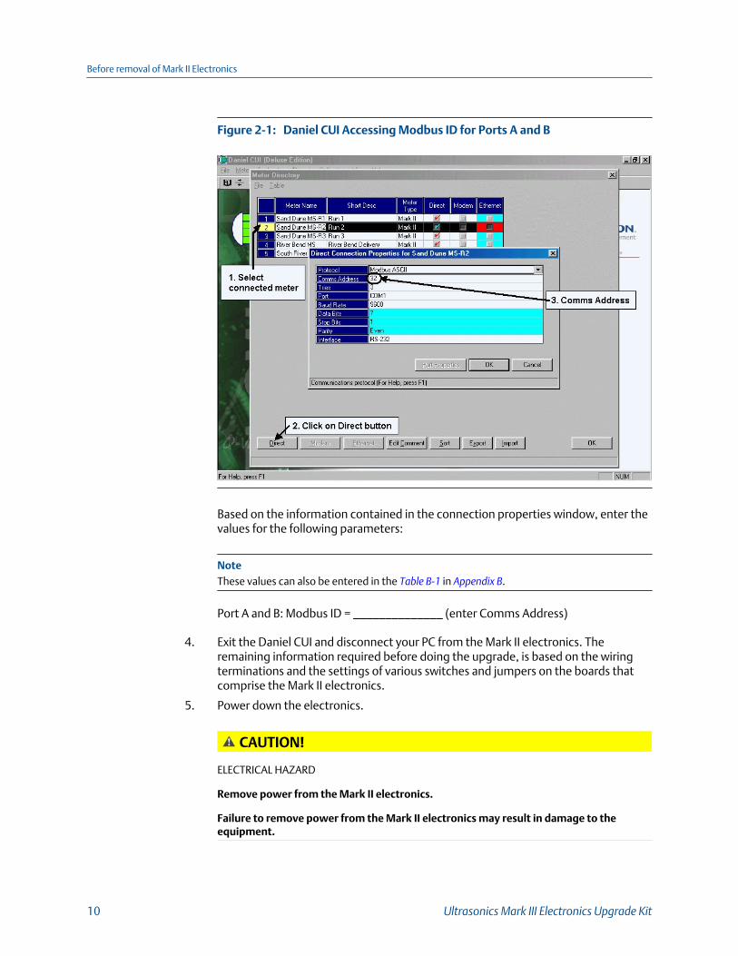
Daniel CUI Accessing Modbus ID for Ports A and BFigure 2-1:
Based on the information contained in the connection properties window, enter thevalues for the following parameters:
NoteThese values can also be entered in the Table B-1 in Appendix B.
Port A and B: Modbus ID = ______________ (enter Comms Address)
4. Exit the Daniel CUI and disconnect your PC from the Mark II electronics. Theremaining information required before doing the upgrade, is based on the wiringterminations and the settings of various switches and jumpers on the boards thatcomprise the Mark II electronics.
5. Power down the electronics.
CAUTION!
ELECTRICAL HAZARD
Remove power from the Mark II electronics.
Failure to remove power from the Mark II electronics may result in damage to theequipment.
Before removal of Mark II Electronics
10 Ultrasonics Mark III Electronics Upgrade Kit

6. Remove the end caps from the upper electronics housing of the meter to access thetwo sets of circuit boards. See Figure 2-3 for board layout of the stacks.
Remove end caps (picture shows end where wiring is terminated)Figure 2-2:
Drawing of Mark II electronics in housing layoutFigure 2-3:
Before removal of Mark II Electronics
Instructions manual 11

7. The Mark II electronic’s physical configuration regarding the serial communications,frequency outputs and status outputs is required. This information is obtained bychecking the switch and jumper settings on the boards contained in the Mark IIelectronics.
The table below provides the various wiring terminations, switch settings andjumper positions which dictate the signal type (RS-232 or RS-485) for each port. Thewiring terminations, and switch (S1) are located on the Field Connection board(Figure 2-4) and the jumpers (JP1 – JP4) are located on the PS (Power Supply) board(Figure 2-5 and Figure 2-6). As shown in Figure 2-3, these two boards are located onthe outer ends of the electronics and are clearly viewable when the end caps on thehousing have been removed. The location of the switch and jumpers are shown in Figure 2-4 and Figure 2-5.
RS-232 and RS-485 Serial Communications SetupTable 2-1:
Field Connection Board Power Supply Board
PortADriv-er
PortBDriv-er
Port A Wir-ing Connec-tions
Port B Wir-ing Connec-tions
S1 JP1 JP2 JP3 JP4 JP5 JP6
Wire Con-nec-tor
Wire Con-nec-tor
RS485
RS485
485+
485-
485C
485+
485-
485C
485+
485-
485C
RTS
RXD
232C
EIA485
closed
closed
closed
closed
closed
closed
RS485
RS232C
485+
485-
485C
485+
485-
485C
232TXD
232RXD
232C
RTS
RXD
232C
EIA485
closed
closed
closed
open open open
RS232C
RS232C
232TXD
232RXD
232C
232RTS*
232CTS*
TXD
RXD
232C
RTS
CTS
232TXD
232RXD
232C
485+
485-
485C
RS232
open open open open open open
Before removal of Mark II Electronics
12 Ultrasonics Mark III Electronics Upgrade Kit

RS-232 and RS-485 Serial Communications Setup (continued)Table 2-1:
Field Connection Board Power Supply Board
RS232C
RS485
232TXD
232RXD
232C
232RTS*
232CTS*
TXD
RXD
232C
RTS
CTS
485+
485-
485C
485+
485-
485C
RS232
closed
closed
closed
open open open
(*) RS-232C handshaking signals (RTS/CTS) are optional for Port A.
Based on Table 2-1, indicate the signal type for each port.
Port A: RS-232 or RS-485 (circle one)
Port B: RS-232 or RS-485 (circle one)
Field Connection Board showing Switch S1 locationFigure 2-4:
NoteThe PFC (Peripheral Field Connection) Board is mounted in front of the Field Connection Board
Before removal of Mark II Electronics
Instructions manual 13

Power Supply Board showing location of Jumpers JP1 - JP6Figure 2-5:
8. See Figure 2-6 for jumper locations and settings information. The PFC board lookslike 2/3 of a disk (see Figure 2-3 and Figure 2-4 for location). Jumpers JP1 to JP6 definethe frequency and status output signal types as TTL or OC (open collector).
PFC (Peripheral Field Connection) Board showing JP1 - JP6Figure 2-6:
These jumpers will be in either position A, setting the outputs to TTL, or position B,setting the outputs to open collector. The simplified sketch below shows the twosettings for these jumpers.
Before removal of Mark II Electronics
14 Ultrasonics Mark III Electronics Upgrade Kit

Simplified sketch of Jumpers A and BFigure 2-7:
Based on the position of the each of the jumpers J1 - J6 on the Peripheral FieldConnection board, the signal type for each of the outputs can be determined byindicating the position in Table 2-2. (Place a check in the applicable position columnfor each of the jumpers.)
Output Signal TypeTable 2-2:
Output Signal Jumper Position A (TTL)
Position B(open collec-tor)
Frequency 1 FREQ1A JP1
FREQ1B JP2
Frequency 2 FREQ2A JP3
FREQ2B JP4
Flow DirectionOutput
JP5
Validity DigitalOutput
JP6
9. To obtain the remaining physical configuration of the electronics, remove theelectronic assembly comprised of DFI board, Power Supply and CPU board.
To remove the electronics assembly:
a. Remove the cable connector screws on the Power Supply and disconnect thecables.
b. Loosen the 4 captive screws that hold the electronics stack in the housing.
c. Move the field connection boards cables to the right. Then grasp two of thecaptive screws and pull the card stack from the housing.
Before removal of Mark II Electronics
Instructions manual 15

View of Power Supply board with end cap of electronics housingremoved
Figure 2-8:
10. The retaining clips on the screws are located under the lowest board in the stack.Using a small screwdriver pry the retainer rings from the screws. With the ringsremoved, the screws can be pulled through the stack, and the stack can bedisassembled.
11. On the DFI (Digital Frequency Interface) board, (middle board in the stack) there aretwo switch banks, S1 and S2, located near the center of the board, as shown in Figure 2-9. These switches are used to set the Modbus address, protocol and baudrates.
DFI board showing switch banks S1 and S2Figure 2-9:
Before removal of Mark II Electronics
16 Ultrasonics Mark III Electronics Upgrade Kit

Switch bank S2 consists of 8 switches and S1 has 4. The following sketch shows therelative location of the switches on each switch bank.
Sketch of Switches S1 and S2 relative locationFigure 2-10:
2.2 Modbus IDAlthough the Modbus ID may already have been determined from information based onthe “Comms Address” accessed via Daniel CUI (via the Direct ConnectionProperties for …….. window), it is also possible to get this information based onthe positions of switches 1-5 on Switch bank S2.
The address is the binary value of the five switches plus 1. Table 2-3 will assist indetermining the address. Circle the applicable value for each switch based on its position.Then, add up the circled values and add 1.
Modbus ID Table/CalculatorTable 2-3:
Switch Po-sition S2 Switches Sum
1 2 3 4 5
On 0 0 0 0 0
Off 1* 2* 4* 8* 16*
Plus 1
Total =
(*) Values are the default settings (i.e. address = 32)
Modbus ID = _________________________ (total determined in above table)
Before removal of Mark II Electronics
Instructions manual 17

2.3 Port A and B Baud ratesThe position of switches 6 and 7 on Switch bank S2 and switch 4 on Switch bank S1determine the baud rate for Ports A and B respectively, as per the following Table 2-4.
Port A and Port B Baud RatesTable 2-4:
S2 Switch BankPort A BaudRate
S1 SwitchBank
Port B BaudRate
7 6 4
On On 1200 On 2400
Off 2400 Off* 9600*
Off* On 4800
Off* 9600*
(*) Values are the default settings (i.e.9600 baud)
Port A Baud Rate = ____________________
Port B Baud Rate = ____________________
Before removal of Mark II Electronics
18 Ultrasonics Mark III Electronics Upgrade Kit

3 Removal of Mark II Electronics
3.1 Instructions to remove the Mark II ElectronicsHaving obtained all the information related to the set-up of the Mark II configuration andcommunications, all the components related to the Mark II electronics can now bephysically removed.
1. Unscrew all wiring from the Field Connection and PFC board termination strips. Itmay be helpful to label the wires to make it easier to connect the Mark III electronics.
2. Remove the conduit and wiring attached to all of the six conduit ports.
3. Remove any ground wire attached to the ground lug on the outside of the upperelectronics housing. At this point there should be no wires connected to the upperelectronics housing.
Remove ground wireFigure 3-1:
4. Use the 6mm Allen wrench (supplied with upgrade kit) to remove the four boltsholding the base enclosure cover to the base enclosure.
Bolt removed from baseFigure 3-2:
5. Remove the upper electronics housing from the base enclosure.
Removal of Mark II Electronics
Instructions manual 19
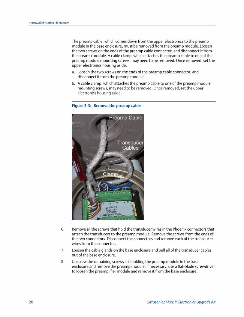
The preamp cable, which comes down from the upper electronics to the preampmodule in the base enclosure, must be removed from the preamp module. Loosenthe two screws on the ends of the preamp cable connector, and disconnect it fromthe preamp module. A cable clamp, which attaches the preamp cable to one of thepreamp module mounting screws, may need to be removed. Once removed, set theupper electronics housing aside.
a. Loosen the two screws on the ends of the preamp cable connector, anddisconnect it from the preamp module.
b. A cable clamp, which attaches the preamp cable to one of the preamp modulemounting screws, may need to be removed. Once removed, set the upperelectronics housing aside.
Remove the preamp cableFigure 3-3:
6. Remove all the screws that hold the transducer wires in the Phoenix connectors thatattach the transducers to the preamp module. Remove the screws from the ends ofthe two connectors. Disconnect the connectors and remove each of the transducerwires from the connector.
7. Loosen the cable glands on the base enclosure and pull all of the transducer cablesout of the base enclosure.
8. Unscrew the remaining screws still holding the preamp module in the baseenclosure and remove the preamp module. If necessary, use a flat-blade screwdriverto loosen the preamplifier module and remove it from the base enclosure.
Removal of Mark II Electronics
20 Ultrasonics Mark III Electronics Upgrade Kit

9. The four mounting bolts holding the enclosure cover to the meter body are sealedwith a RTV silicone adhesive/sealant. Remove the RTV with a flat-blade screwdriveror utility knife to expose the mounting bolts. Running a utility knife around theperimeter of the recessed opening and the RTV eases the removal of the sealant.Use the 7/16" socket wrench to remove the four mounting bolts.
Remove old RTVFigure 3-4:
10. Remove the base enclosure from the meter body.
11. If RTV silicone adhesive/sealant was used to seal the base enclosure to the meterbody, remove it from the meter body so the Mark III base enclosure will have a cleanmounting surface.
12. The Mark II electronics should be completely removed from the meter body.
Removal of Mark II Electronics
Instructions manual 21

Removal of Mark II Electronics
22 Ultrasonics Mark III Electronics Upgrade Kit

4 Installation of Mark III
4.1 Instructions to install the Mark III Electronics1. Remove the Mark III Upgrade components from the packaging. Use the 6mm Allen
wrench to remove the two screws from the base enclosure cover.
Remove bolts from enclosureFigure 4-1:
2. Lift the upper electronics housing from the base enclosure. The acquisition cableconnector from the upper electronics is attached to the acquisition module with twoscrews. Loosen the two screws and disconnect the acquisition cable connector fromthe acquisition module.
Remove acquisition cable and moduleFigure 4-2:
3. Unscrew the three mounting screws from the acquisition module in the baseenclosure and remove the acquisition board.
4. Place an insulating gasket on the meter body where the electronics will be mounted.
Installation of Mark III
Instructions manual 23

Position insulating gasketFigure 4-3:
5. Place the base enclosure on top of the meter body on top of the insulating gasket.Note that the transducer port openings on the base enclosure are labeled withtransducer locations (i.e. A1, A2.. D1, D2).
a. Orient the base so that the A1 transducer port is closest to the A1 transducerlocation on the meter body. The meter body has the transducer location labelsembossed in the body next to each transducer boss. The ports on the baseenclosure must be oriented outward (towards the sides of the meter body,perpendicular to meter axis). This will be different from the Mark II baseenclosure orientation on which the transducer ports were oriented towards theflanges, in line with the meter axis
Base enclosure orientationFigure 4-4:
6. Use the four 1/4" bolts with stainless steel washers and nylon shoulder washers tosecure the base enclosure to the meter body. Use a nut driver to tighten the bolts toa torque of 55 to 65 inch-lbs.
Installation of Mark III
24 Ultrasonics Mark III Electronics Upgrade Kit

Insert 1/4" boltsFigure 4-5:
7. Fill up the wells with RTV adhesive/sealant around and over the four 1/4" bolts. Thiswill ensure a water-tight seal. Any excess sealant can be removed by using a scraperto leave the sealant flush with the top of the well. Excess sealant will adhere to theacquisition board when it is installed, and make future removal of the board difficult.
Apply RTV sealant around boltsFigure 4-6:
8. Insert the Mark III Acquisition board in the base enclosure and secure it with thethree screws. It can only be installed in one orientation.
9. If the transducer cables are black, then the metallic glands must be moved overfrom the Mark II electronics. If Mark II has plastic glands, then you will need topurchase metal glands. If the meter is an explosion-proof Cenelec meter, theexplosion-proof glands will have to be moved over to the Mark III electronics.
10. Thread the transducer cables from the transducers through the cable gland on theappropriate port of the new base enclosure. Each transducer location on the meterbody is marked (example: A1, A2). The A1 transducer cable must go through the A1port on the base enclosure. The same applies to all other transducer cables.
11. The cable entries on the Mark III base are perpendicular to the meter axis as opposedto parallel to the axis on the Mark II body. The orientation of the wiring may need tobe shortened. Cut the transducer cables to the correct length with allowance for thewiring terminations and connector placement. Strip back about 1.5" of the cableouter sheath and 1/4" inch of insulation off the white and black wires as shownbelow in Figure 4-7. When stripping back the outer sheath of the transducer cable,do not cut into the insulation of the individual wires. The transducer cables havethree wires each, that must be terminated on the applicable connector which plugsinto the acquisition board. The white wire goes to the + (positive) pin, the black wiregoes to the - (negative) pin and the bare drain wire goes to the Spin.
Installation of Mark III
Instructions manual 25

NoteOn some of the old black transducer cables, the positive wire may be blue and the negativewire may be gray.
Trim transducer cablesFigure 4-7:
The relative position of the contacts is shown on the acquisition board label adjacentto the Phoenix connector plug-in. Use caution here as the sequence of the wires areopposite in the two sides (ie S - + and + - S). When the wires are being terminated onthe connector, ensure that the contacts clamp on the bare wires and not on the wireinsulation. Leave the connector plugged into the Acquisition board whileterminating the individual wires. After terminating all the wires on the applicableconnector, replace the connector screws on either end of the connector. Repeat thisprocedure for the transducer cables on the other side of the meter.
Install cable and secure wiresFigure 4-8:
12. Secure the transducer cables in such a fashion that they are neat, and do not haveundo exposure to potential physical damage.
Installation of Mark III
26 Ultrasonics Mark III Electronics Upgrade Kit
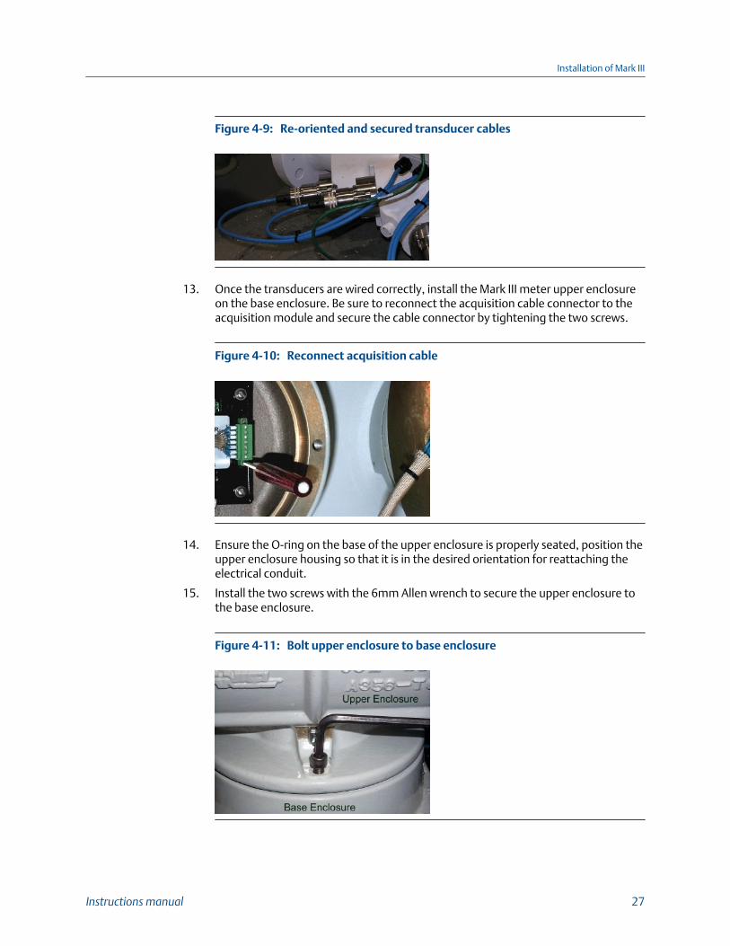
Re-oriented and secured transducer cablesFigure 4-9:
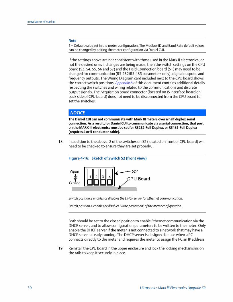
13. Once the transducers are wired correctly, install the Mark III meter upper enclosureon the base enclosure. Be sure to reconnect the acquisition cable connector to theacquisition module and secure the cable connector by tightening the two screws.
Reconnect acquisition cableFigure 4-10:
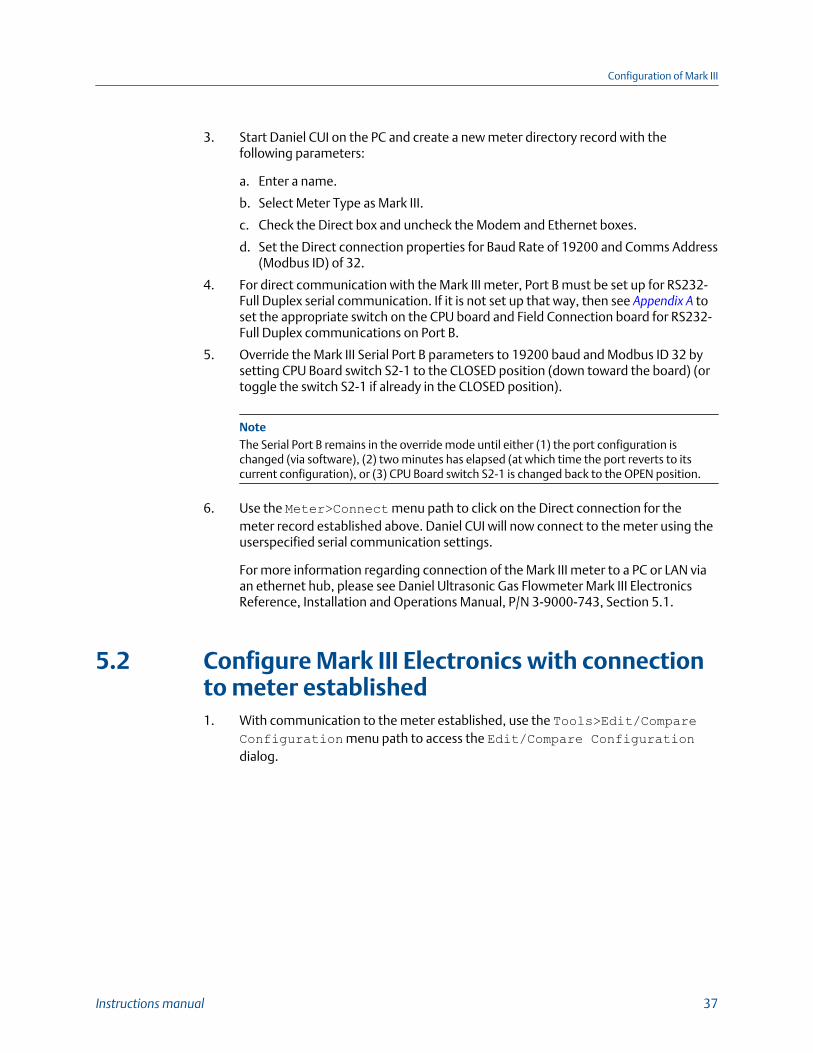
14. Ensure the O-ring on the base of the upper enclosure is properly seated, position theupper enclosure housing so that it is in the desired orientation for reattaching theelectrical conduit.
15. Install the two screws with the 6mm Allen wrench to secure the upper enclosure tothe base enclosure.
Bolt upper enclosure to base enclosureFigure 4-11:
Installation of Mark III
Instructions manual 27

16. Remove both end caps from the upper enclosure. Figure 4-12 shows the layout ofthe Mark III electronics. As can be seen the number of boards has been reduced totwo (CPU and Field Termination boards with provision for an Option board) andaccess to those boards has been simplified.
Drawing of Mark III electronics layoutFigure 4-12:
17. Remove the Wiring Diagram card. Remove the CPU board from the upper enclosure.There are locks on each rail that must be disengaged by pushing them in thedirection indicated on the labels in the enclosure, adjacent to the locks (See Figure 4-14 and Figure 4-15).
Remove CPU boardFigure 4-13:
Installation of Mark III
28 Ultrasonics Mark III Electronics Upgrade Kit

Locked - metal button out in direction of the locked symbolFigure 4-14:
Unlocked - metal button pushed in away from locked symbolFigure 4-15:
The following table shows the default communications and output settings for theMark III electronics and configuration:
Default Communications and Output Settings for the Mark IIITable 4-1:
Communication/Output Parameter Applies to Default Setting Notes
Modbus ID Ports A and B 32 1
Driver Port A RS485 Half Duplex
Port B RS232 Half Duplex
Baud Rate Port A 9600 1
Port B 19,200 1
Frequency 1 Output 1A OC
1B OC
Frequency 2 Output OC
2A OC
Flow Direction Out-put
OC
Validity Output 2B OC
Installation of Mark III
Instructions manual 29
Note1 = Default value set in the meter configuration. The Modbus ID and Baud Rate default valuescan be changed by editing the meter configuration via Daniel CUI.
If the settings above are not consistent with those used in the Mark II electronics, ornot the desired ones if changes are being made, then the switch settings on the CPUboard (S3, S4, S5, S6 and S7) and the Field Connection board (S1) may need to bechanged for communication (RS-232/RS-485 parameters only), digital outputs, andfrequency outputs. The Wiring Diagram card included next to the CPU board showsthe correct switch positions. Appendix A of this document contains additional detailsrespecting the switches and wiring related to the communications and discreteoutput signals. The Acquisition board connector (located on IS Interface board onback side of CPU board) does not need to be disconnected from the CPU board toset the switches.
NOTICEThe Daniel CUI can not communicate with Mark III meters over a half duplex serialconnection. As a result, for Daniel CUI to communicate via a serial connection, that porton the MARK III electronics must be set for RS232-Full Duplex, or RS485-Full Duplex(requires 4 or 5 conductor cable).
18. In addition to the above, 2 of the switches on S2 (located on front of CPU board) willneed to be checked to ensure they are set properly.
Sketch of Switch S2 (front view)Figure 4-16:
Switch position 2 enables or disables the DHCP server for Ethernet communication.
Switch position 4 enables or disables "write protection" of the meter configuration.
Both should be set to the closed position to enable Ethernet communication via theDHCP server, and to allow configuration parameters to be written to the meter. Onlyenable the DHCP server if the meter is not connected to a network that may have aDHCP server already running. The DHCP server is designed for use when a PCconnects directly to the meter and requires the meter to assign the PC an IP address.
19. Reinstall the CPU board in the upper enclosure and lock the locking mechanisms onthe rails to keep it securely in place.
Installation of Mark III
30 Ultrasonics Mark III Electronics Upgrade Kit

Lock CPU board back in place by pulling the metal button indirection of locked symbol
Figure 4-17:
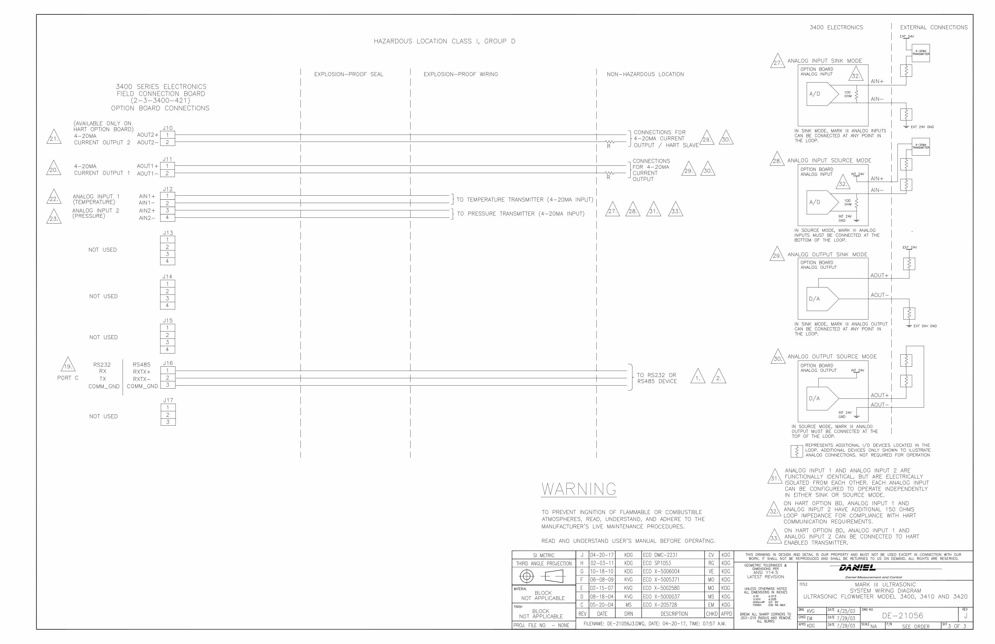
20. Wire all of the electrical conduit connections. The Wiring Diagram card includednext to the CPU board shows the pin-outs for wiring the Field Connection board. Allof the terminations on the Field Connection board are made with the Phoenix quickdisconnect connectors. This makes it easier to terminate the wires prior to pluggingthem into the board. Appendix A of this document also includes wiring tables andillustrations for each of the connectors on the Field Connection board. Refer to fieldwiring drawing DE-21056 in Appendix C.
Install wiring via the Phoenix connectors to the Field Connectionboard
Figure 4-18:
21. Install a ground wire to the ground lug on the side of the upper enclosure.
Installation of Mark III
Instructions manual 31

Attach ground wireFigure 4-19:
WARNING!EXPLOSION HAZARD
Do not apply power to the meter with the end caps removed unless you are in anonhazardous or explosive-free environment.
Failure to ensure that an explosive environment is not present could result in death orserious injury and possible equipment damage.
This completes the installation of the hardware associated with the Mark III meterupgrade.
Installation of Mark III
32 Ultrasonics Mark III Electronics Upgrade Kit

Part IIIOperate
Operate
Instructions manual 33

Operate
34 Ultrasonics Mark III Electronics Upgrade Kit

5 Configuration of Mark IIITopics covered in this chapter:
• Initial instructions to configure the Mark III Electronics
• Configure Mark III Electronics with connection to meter established
5.1 Initial instructions to configure the Mark IIIElectronics1. Check all settings and wiring carefully.
2. Set up the Meter Directory, and start initial communication with the Mark IIIelectronics. The basic instructions for setting up the directory and initializingcommunications are contained in the following text. Refer to the Daniel UltrasonicGas Flowmeter Mark III Electronics Reference, Installation and Operations Manual,P/N 3-9000-743, in Section 5.1 for more detailed instructions. Use Daniel CUI 3.1 orlater to make a connection to the meter.
5.1.1 Initial communication connection using EthernetEthernet Initial Connection Material Checklist
The following materials and information are required:
• Mark III Ethernet adapter cable (Daniel P/N 3-3400-079)
• Personal computer (PC) configured as follows:
- Daniel CUI software installed (version 3.1 or higher)
- Ethernet LAN adapter
- Configured to automatically obtain IP address (via DHCP)
• Desired Mark III meter(s) communication configuration parameters:
- IP address
- Serial communication parameters such as baud rate and Modbus ID (if desired)
Steps for Ethernet initial connection1. Power up the Mark III meter.
2. Shutdown the PC.
3. Plug the Mark III Ethernet adapter cable Phoenix end into the meter FieldConnection Board connector J8 and connect the RJ45 end into the PC Ethernetconnector.
4. Ensure that the Ethernet LAN connector DHCP server is enabled on the Mark III CPUBoard by setting switch S2-2 to the CLOSED position (down toward the board).
5. Power up (boot) the PC and log in to the initial Windows logon prompt.
Configuration of Mark III
Instructions manual 35

6. Verify the Ethernet connection status by the Mark III CPU Board "LINK” LED whichshould be on solid green. The “LINK” LED is the 5th from the top at the front of theCPU board. (See card in enclosure for LED descriptions).
7. Start Daniel CUI on the PC. The Connect to Meter dialog displays. Click the EditMeter Directory button. Click the Add button (below the Meter Directory fileoperations field). Daniel CUI inserts the New Meter record in the last field in the MeterDirectory table.
8. Create a new meter directory record with the following parameters:
a. Enter a name for the meter.
b. Select Meter Type as Mark III.
c. Check the Ethernet box and uncheck the Direct and Modem boxes.
d. Set the Ethernet IP address to 192.168.135.100.
e. Close the Meter Directory window
9. Use the Meter>Connect menu path to click on the Ethernet connection for themeter record established in the previous step. Daniel CUI will now connect to themeter using the user-specified Ethernet settings.
5.1.2 Initial communication connection using RS-232 serialRS-232 Serial Initial Connection Material Checklist
The following materials and information are required:
• Ultrasonic serial cable (Daniel P/N 3-2500-401)
• Personal computer (PC) with Daniel CUI software version 3.1
• Desired Mark III meter(s) communication configuration parameters:
- IP address (if desired)
- Serial communication parameters such as baud rate and Modbus ID
Steps for RS-232 serial initial connection1. Power up the Mark III meter and the PC.
2. Plug the DB-9 end of the cable directly into the PC running Daniel CUI. The threewires on the other end of the cable connect to J7 (FTB) for Port B. The Digital Outwire goes to J7-Pinl, the Digital In wire goes to J7-Pin2, and the COMMON wire goesto J7-Pin3.
J7 PIN Wire ColorsTable 5-1:
J7 PIN Wire Colors Wire Color
1 Red
2 White
3 Black
Configuration of Mark III
36 Ultrasonics Mark III Electronics Upgrade Kit
3. Start Daniel CUI on the PC and create a new meter directory record with thefollowing parameters:
a. Enter a name.
b. Select Meter Type as Mark III.
c. Check the Direct box and uncheck the Modem and Ethernet boxes.
d. Set the Direct connection properties for Baud Rate of 19200 and Comms Address(Modbus ID) of 32.
4. For direct communication with the Mark III meter, Port B must be set up for RS232-Full Duplex serial communication. If it is not set up that way, then see Appendix A toset the appropriate switch on the CPU board and Field Connection board for RS232-Full Duplex communications on Port B.
5. Override the Mark III Serial Port B parameters to 19200 baud and Modbus ID 32 bysetting CPU Board switch S2-1 to the CLOSED position (down toward the board) (ortoggle the switch S2-1 if already in the CLOSED position).
NoteThe Serial Port B remains in the override mode until either (1) the port configuration ischanged (via software), (2) two minutes has elapsed (at which time the port reverts to itscurrent configuration), or (3) CPU Board switch S2-1 is changed back to the OPEN position.
6. Use the Meter>Connect menu path to click on the Direct connection for themeter record established above. Daniel CUI will now connect to the meter using theuserspecified serial communication settings.
For more information regarding connection of the Mark III meter to a PC or LAN viaan ethernet hub, please see Daniel Ultrasonic Gas Flowmeter Mark III ElectronicsReference, Installation and Operations Manual, P/N 3-9000-743, Section 5.1.
5.2 Configure Mark III Electronics with connectionto meter established1. With communication to the meter established, use the Tools>Edit/Compare
Configuration menu path to access the Edit/Compare Configurationdialog.
Configuration of Mark III
Instructions manual 37

Edit/Compare Configuration dialogFigure 5-1:
2. Click on the Open button. The Open Configuration File displays. Select thefinal Mark II configuration file created in Step 2 of Section 2.1 of this document (i.e."Meter Name, MkII Final Config, 3-4-2005 10-15-02 AM.cfg"). Click on the Openbutton. The file opens and you are returned to the Edit CompareConfiguration dialog.
Open Configuration File dialogFigure 5-2:
Configuration of Mark III
38 Ultrasonics Mark III Electronics Upgrade Kit

a. Click on the Convert button (see Figure 5-3). Daniel CUI reads the Mark IIIconfiguration from the meter and modifies it with the Mark II configuration. Alldata points shown in yellow have been modified from the Mark II configuration.
Edit/Compare Configuration dialog with active “Convert”button
Figure 5-3:
Converted Configuration with highlighted changesFigure 5-4:
Configuration of Mark III
Instructions manual 39

b. To write the converted configuration to the meter, click on the Write Checkedbutton (see Figure 5-4). If an error occurs, Daniel CUI will display a messageindicating the nature of the problem. This will necessitate that the problematicparameter be edited manually. In order to successfully complete the download.After modifying the parameter(s), click Write Checked again. Repeat this untilthe write occurs with no errors.
c. Save the Mark III electronics configuration file to your PC. With the convertedconfiguration still displayed, from the Edit/Compare Configurationdialog, click on the Meter radio button, located next to the Compare buttonwhich is grayed out in this example (see Figure 5-1). Compare the file to verifythat this saved configuration matches the meter configuration. If an error occurs,go back to the beginning of Step 1 and try again until no errors are reported.
3. Use the Meter>Monitor menu path to display the Monitor window and verifythat the meter is operating correctly.
Meter Monitor dialogFigure 5-5:
4. Use the Meter>Communications Settings menu path to access theCommunications dialog. This dialog displays the communications parameters forthe Mark III electronics and is used to adjust the Baudrate and Comms Address (i.e.Modbus ID) for the serial ports.
You do not need to set the Protocol (ASCII or RTU) because the Mark III auto-detectsthe protocol.
Configuration of Mark III
40 Ultrasonics Mark III Electronics Upgrade Kit

Communications Settings dialogFigure 5-6:
5. Use the Meter>Field Setup Wizard menu path to access the Field SetupWizard startup dialog. Verify that all settings are correct (e.g., temperature,pressure, meter connections and meter outputs). In the Meter name field, insert aname for the meter (this name displays on Daniel CUI main window). Ensure theMark III digital outputs are configured appropriately. The Mark III also supports, andmay be configured for, the AGA8 Detailed Method.
Configuration of Mark III
Instructions manual 41

Field Setup Wizard Startup dialogFigure 5-7:
6. If changes were made in the Field Setup Wizard, choose to save theconfiguration when Daniel CUI prompts you after the changes are written to themeter.
7. You have successfully completed upgrading your Mark II to a Mark III electronics.Click on the Finish button in the Wizard dialog to write any changes to the meter.
Configuration of Mark III
42 Ultrasonics Mark III Electronics Upgrade Kit

Appendix AMark III field connection and CPU boards
Mark III Field Connection Board Switches and ConnectorsFigure A-1:
Mark III field connection and CPU boards
Instructions manual 43

Mark III CPU Board SwitchesFigure A-2:
NoteThe switch positions shown in the sketches of the switch banks are the factory default positions.
Mark III field connection and CPU boards
44 Ultrasonics Mark III Electronics Upgrade Kit

RS-232 and RS-485 Serial Communications Setup
RS-232 Full DuplexFigure A-3:
Mark III field connection and CPU boards
Instructions manual 45
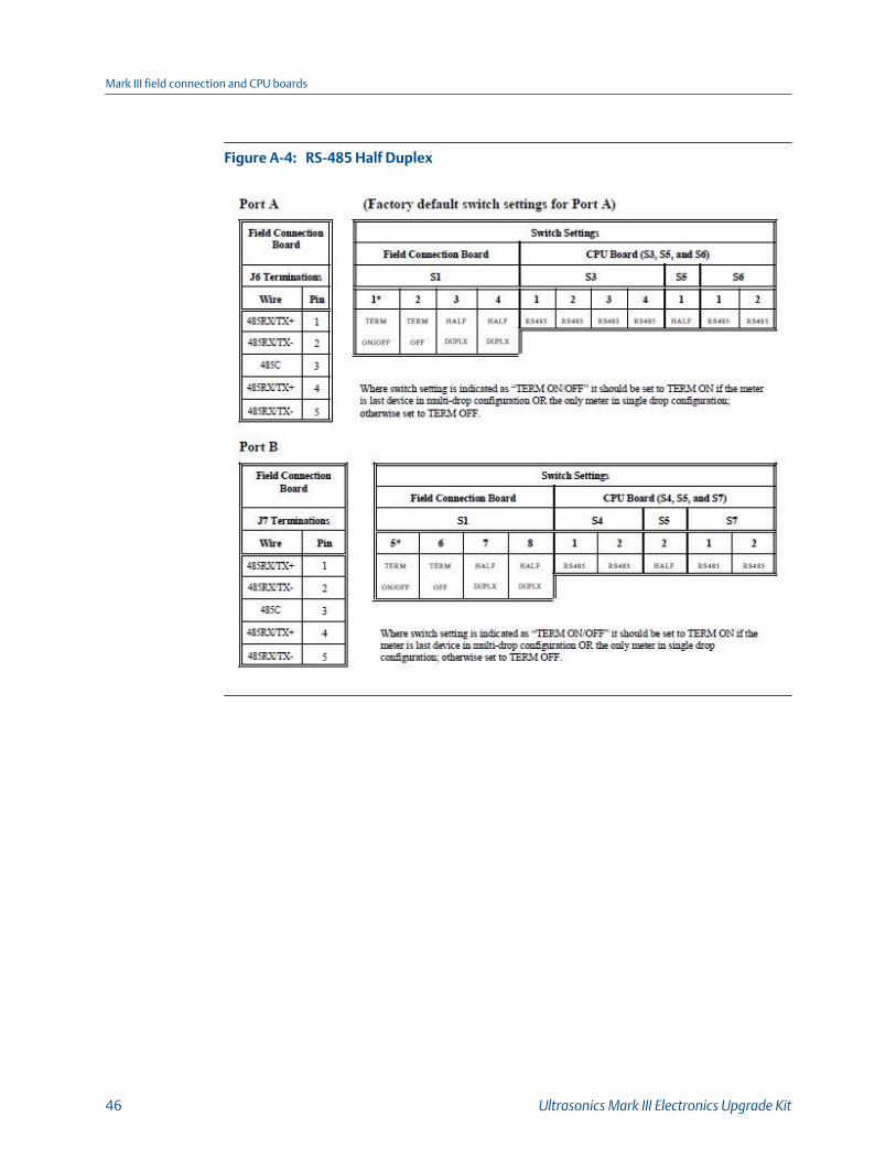
RS-485 Half DuplexFigure A-4:
Mark III field connection and CPU boards
46 Ultrasonics Mark III Electronics Upgrade Kit

RS-485 Full DuplexFigure A-5:
Mark III field connection and CPU boards
Instructions manual 47

Discrete Output Switch Settings
Groups 1 and 2 FO and DOFigure A-6:
Mark III field connection and CPU boards
48 Ultrasonics Mark III Electronics Upgrade Kit

Series 100 Option Board (if installed)Figure A-7:
RS-232 Full DuplexFigure A-8:
Mark III field connection and CPU boards
Instructions manual 49
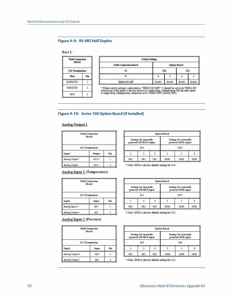
RS-485 Half DuplexFigure A-9:
Series 100 Option Board (if installed)Figure A-10:
Mark III field connection and CPU boards
50 Ultrasonics Mark III Electronics Upgrade Kit
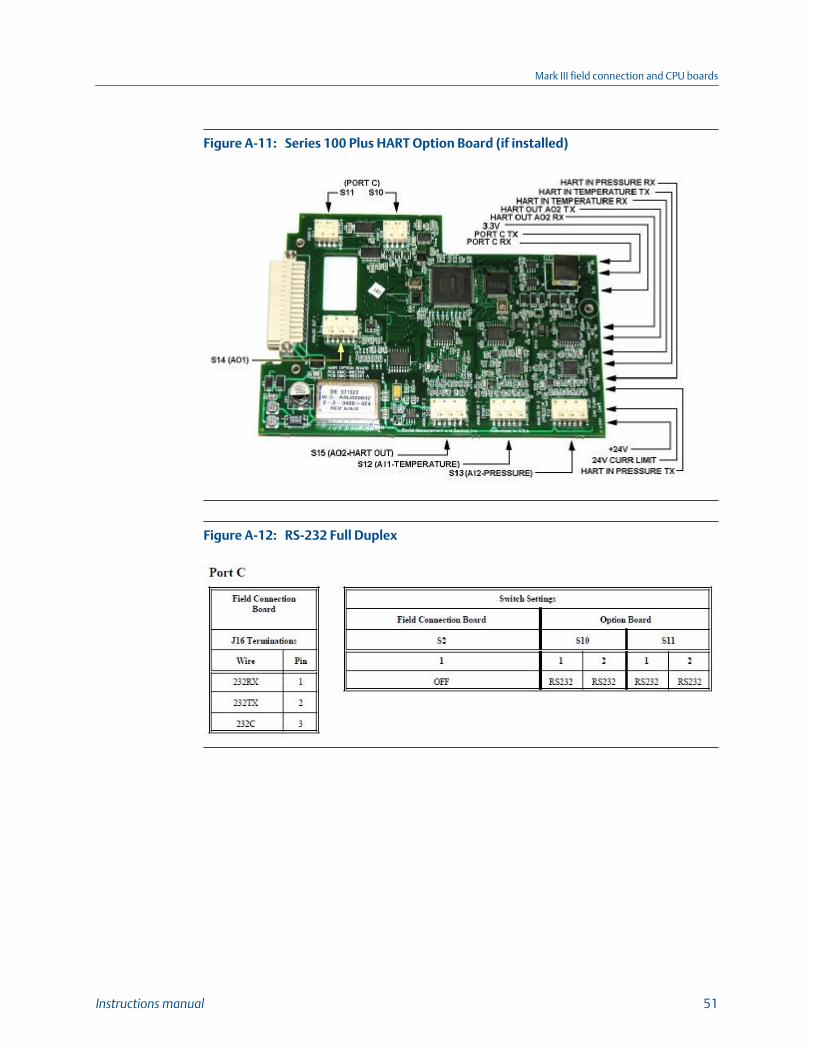
Series 100 Plus HART Option Board (if installed)Figure A-11:
RS-232 Full DuplexFigure A-12:
Mark III field connection and CPU boards
Instructions manual 51

RS-485 Half DuplexFigure A-13:
Mark III field connection and CPU boards
52 Ultrasonics Mark III Electronics Upgrade Kit
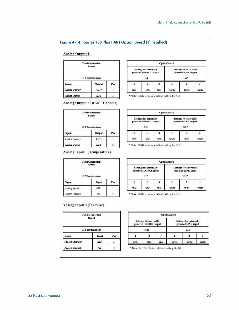
Series 100 Plus HART Option Board (if installed)Figure A-14:
Mark III field connection and CPU boards
Instructions manual 53

Mark III field connection and CPU boards
54 Ultrasonics Mark III Electronics Upgrade Kit
Appendix BSummary table of communications/outputsettings
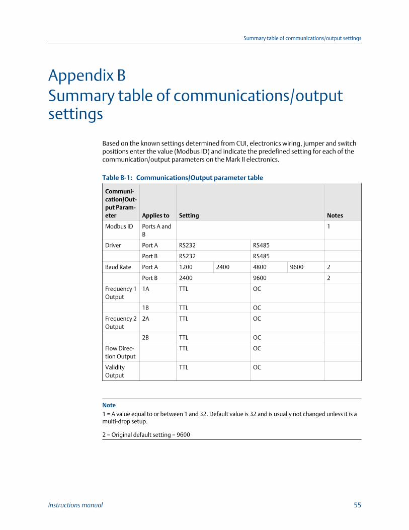
Based on the known settings determined from CUI, electronics wiring, jumper and switchpositions enter the value (Modbus ID) and indicate the predefined setting for each of thecommunication/output parameters on the Mark II electronics.
Communications/Output parameter tableTable B-1:
Communi-cation/Out-put Param-eter Applies to Setting Notes
Modbus ID Ports A andB
1
Driver Port A RS232 RS485
Port B RS232 RS485
Baud Rate Port A 1200 2400 4800 9600 2
Port B 2400 9600 2
Frequency 1Output
1A TTL OC
1B TTL OC
Frequency 2Output
2A TTL OC
2B TTL OC
Flow Direc-tion Output
TTL OC
ValidityOutput
TTL OC
Note1 = A value equal to or between 1 and 32. Default value is 32 and is usually not changed unless it is amulti-drop setup.
2 = Original default setting = 9600
Summary table of communications/output settings
Instructions manual 55

Summary table of communications/output settings
56 Ultrasonics Mark III Electronics Upgrade Kit

Appendix CEngineering Drawings
DE-21056 Mark III Ultrasonic System Wiring, UltrasonicFlowmeter Model 3400, 3410 and 3420 (Sheets1-3)
Engineering Drawings
Instructions manual 57

Engineering Drawings
58 Ultrasonics Mark III Electronics Upgrade Kit


P/N 3-9000-746
Rev K
2018
Emerson Automation SolutionsDaniel Measurement and Control, Inc.North America / Latin America:HeadquartersUSA - Houston, TexasT +1.713.467.6000USA Toll Free 1.888.FLOW.001www.daniel.com
Europe: Stirling, Scotland, UKT +44.1786.433400Middle East, Africa: Dubai, UAET +971.4.811.8100Asia Pacific: SingaporeT +65.6777.8211
©2018 Daniel Measurement and Control, Inc. All rights reserved. Unauthorized duplication in wholeor part is prohibited. Printed in the USA.
Daniel Measurement and Control, Inc. ("Daniel") is an Emerson Automation Solutions business unit.The Daniel name and logo are trademarks of Daniel Industries, Inc. The Emerson logo is a trademarkand service mark of Emerson Electric Co. All other trademarks are the property of their respectivecompanies.


