Parliament British Museum DAQ Architecture Matthew Wing (UCL) Instrumentation Seminar, DESY, Hamburg, 10 September 2010 • Introduction • Keeping up with technology • The CALICE DAQ system • Discussion and summary Talk based on work done by colleagues at Cambridge, Manchester, RHUL and UCL.
Transcript
Parliament
British Museum
DAQ ArchitectureMatthew Wing (UCL)
Instrumentation Seminar, DESY, Hamburg, 10 September 2010
• Introduction• Keeping up with technology• The CALICE DAQ system• Discussion and summary
Talk based on work done by colleagues at Cambridge, Manchester, RHUL and UCL.
Introduction
2
• High energy physics has long been large-scale science with experiments recording large samples of data.
- Need to read out data from detectors at high speed and efficiency.• How has this changed given other large-scale projects and e.g. expansion of telecommunications industry ?
- What can be learnt from e.g. XFEL and vice versa?• Can DAQ systems be generic for many purposes ?• Can DAQ systems be bought off-the-shelf ?• What are the latest technologies influencing the field ?
Evolution of DAQ in HEP
3
• HEP has been a driving force for technology and the need to transport lots of data fast; now many areas require this.• With experiments often being very different and / or significantly beyond their predecessors, systems were often bespoke and single use. [Technology also develops.]• Build DAQ system last :
- detector requirements clearer;- technology improvements leads to decreased costs;- R&D often not done;- non-generic.
• Using commercial off-the-shelf components is possible—lots of companies make high-throughput network switches; FPGAs can process so much more.
- can reduce costs, development time (fewer prototyping rounds) and risks;- potentially both more and less flexible;- researchers have less control.
Requirements of a DAQ system
4
DAQ systems have to cater for the needs of detectors :• Cope with potentially high data throughout.• Repeat tasks on short time-scales.• Pick-out (“trigger” on) interesting or spectacular events.• Collect data with 100% efficiency.• Monitor electronics and detector, e.g. state, environmental conditions, etc..• Different running or operating conditions, e.g. data taking, calibration, etc..• Pass control and configuration data.• Work for a long time without fault; sufficient spares, technology repairable and / or replaceable.• Integration of many sub-detectors into one DAQ system.• Cope with upgrades of accelerators and detectors.• ...
List depends on where you draw the line between a DAQ system and e.g. offline reconstruction farm or on-detector electronics.
Keeping up with technology
5
Technology advances
6
• Globalisation and WWW have created the need in everyday life for cutting-edge technology.• Telecommunincations industry in particular has seen many advances.• (Potentially) less need for HEP (or science in general) to develop bespoke equipment.• Academic research should embrace advances made in the commercial world.• Some are :
• Capability of FPGAs;• New crate standards;• Links, networks, switching.
• Large-scale science projects can still contribute though.
FPGA performance
7
• Performance has increased dramatically• Include PowerPC cores• Low cost
• Similar to increase in computing capacity.• Used in wide range of industrial and scientific applications.• Processing can be done earlier, i.e. in electronics rather than PC, or later, i.e. in FPGA and not on-detector ASIC.
Accelerating High-Performance Computing with FPGAs, Altera White Paper, http://www.altera.com/literature/wp/wp-01029.pdf
xTCA systems
8
Advanced Telecommunications Computing Architecture (ATCA) is a new standard :• > 100 companies• PMC / AMC mezzanine cardsµTCA (small/dev system)
ATCA (the new standard)
Looks to be the way forward for DAQ systems
Links and networks
9
Serial links are becoming the norm :• faster, more reliable and cheaper than parallel architectures• ethernet, Serial Attached SCSI, PCI Express, ...• E.g. PCI Express :
• x1 ... x32 lanes;• 250–1000 MB/s per lane each way, growing linearly with lane• total throughput 8–32 GB/s
• 10 Gigabit ethernet becoming the standard and being used for future systems• Ethernet has been going for a long time• 10 Gb switches becoming cheaper.
Optical switches
10
• Becoming a new telecom standard• Method of managing optical fibres efficiently and securely.• Used in defence, undersea cabling, ...• Could be used in HEP / science for data transfer from detector
The CALICE DAQ system
11
Calorimetry at the ILC
12
• The e+e− ILC will be a high-precision machine with the need for requisite detectors.• Calorimeters with precise position determination.
- Leads to lots of channels ~ 100 M.- Challenge of data aggregation.
• Accelerator will run at 5 Hz with ~ 3000 bunches each every ~ 300 ns.
- Calorimeter on for 1 ms and off for 200 ms.- Power-pulsing.- When to read out data.
• All data will recorded, i.e. no triggering.
CALICE (final) data rates
13
• CALICE proposes a highly granular electromagnetic calorimeter for the ILC.• Assume :
- 0.5 × 0.5 cm2 channels;- 100 M channels in total;- 6000 detector “slabs”;- raw data size of 2 Bytes/channel, with 4 Bytes/channel for labelling.
• Data size/bunch train = (100 × 106)⋅(2625) ⋅(6) = 1575 GBytes• Readout during bunch train = (1575 GB) / (2625 × 369 ns) = 1626 TBytes/s, or 271 GBytes/s/slab which is very challenging.• Obvious solution :
- assume pessimistic threshold suppression reduction factor of 100;- data read out between bunch trains (200 ms instead of 1 ms).
• Readout speed = (1575 GB) / (100) / (0.2 s) = 79 GBytes/s, or 0.1 Gbit/s/slab which is clearly far more manageable.
Initial strategy
14
• Basic R&D into DAQ systems for itself and for calorimeters at the ILC.• Have a conceptual design of a DAQ system for calorimetry at the ILC (even though far off).• Develop a system using industrial standards and advances :
• flexible, high-speed serial links; • standards based;• scalable; • easily upgradeable;• using commercial off-the-shelf components;• backplaneless.
• Deliver working DAQ system for CALICE/EUDET prototype calorimeters. • DAQ system could be applicable for final calorimeters or other detector systems.
Example “final” systems
15
PC
DataReduction1000x
5000Slabs
M acroEventBuilderPC
4x50x1Gb
100000Fibres
Busy
20x1Gb
TargetControl
10Gb
Network Switch100Gb
Slab
500PCs
Layer-1 Switch
1Gb
M acroEventBuilderPC
PC PC PC
5000Slabs
5000fibres
Busy
1Gb
TargetControl
10GbSlab
EventBuilderPCs
M acroEventBuilderPC
M acroEventBuilderPC
M acroEventBuilderPC
EventBuilderPCs
EventBuilderPCs
Large Network Switch Farm5Tb
250PCs
Slab
Slab
Slab
Slab
Slab
Slab
Slab
Slab
Slab
Slab
Slab
Slab
Slab
Slab
Slab
Slab
Slab
Slab
Slab
Slab
Slab
Slab
500 fibres
Large Network Switch Farm5Tb
Large Network Switch Farm5Tb
Calorimeter prototypes
16
HCAL
• Building large-scale prototypes for technological tests and test-beam campaign.• The DAQ system will cope with several calorimeters : ECAL, AHCAL, DHCAL (+).• Different beam and / or timing structures.• Comparable in size and complexity to a conventional HEP experiment.
17
DAQ PC
LDA
LDA
ODR
Detector
Unit DIF
CCC
Detector
Unit DIF
Detector
Unit DIF
Detector
Unit DIF
Storage Control
PC
DAQ PC
ODR
Overall DAQ architectureDetector Unit : ASICsDIF : Detector InterFace connects generic DAQ and services to different detectorsLDA : Link/Data Aggregator fansout/in DIFs and drives links to ODR
ODR : Off-Detector Receiver is PC interface CCC : Clock and Control Card fansout to LDAsControl PC : Controls the system
×10
×4
Data links
18
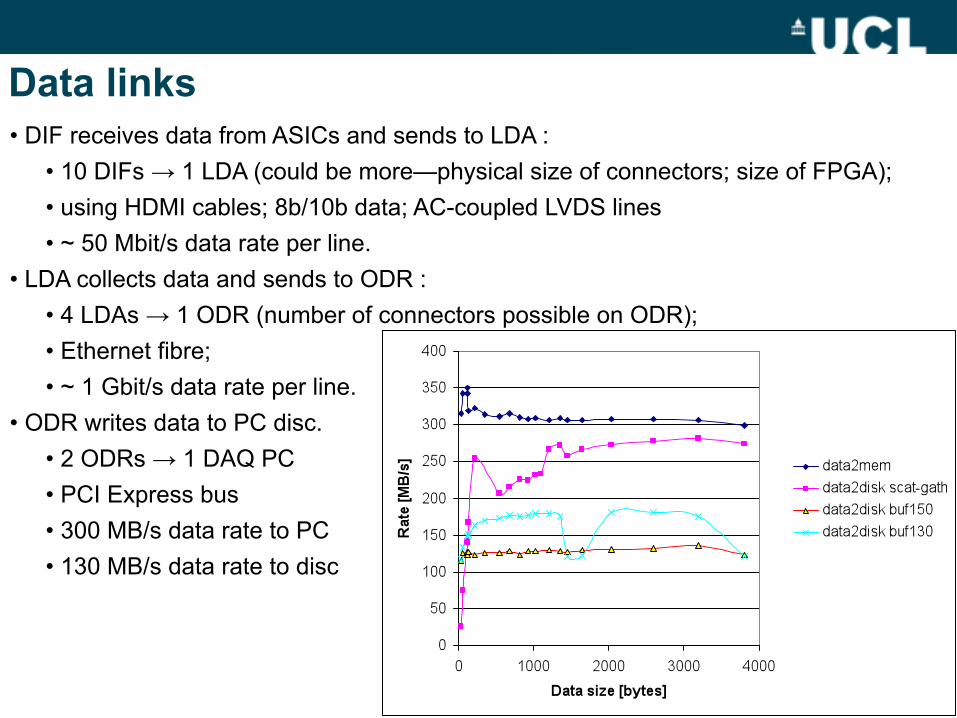
• DIF receives data from ASICs and sends to LDA :• 10 DIFs → 1 LDA (could be more—physical size of connectors; size of FPGA);• using HDMI cables; 8b/10b data; AC-coupled LVDS lines• ~ 50 Mbit/s data rate per line.
• LDA collects data and sends to ODR :• 4 LDAs → 1 ODR (number of connectors possible on ODR);• Ethernet fibre;• ~ 1 Gbit/s data rate per line.
• ODR writes data to PC disc.• 2 ODRs → 1 DAQ PC• PCI Express bus• 300 MB/s data rate to PC• 130 MB/s data rate to disc
• Proposed Digital Calorimeter has far more channels and hence more DIFs, three per layer → 120 DIFs :
• more LDAs;• another cheaper layer of concentration;• LDA with more connectors.
• Need to have a system to read these out and systems to be used in test stands around various labs.• Including sufficient spares means need ≥ 5 × above LDAs, CCCs, ODRs.• Significant outlay and cost.
The DIF (Detector InterFace)
20
• Each calorimeter needs a detector-specific interface.• Board “on-detector” at end of calorimeter slab.• Built in close collaboration by different groups for each calorimeter.• Different mechanics and signals which are then handled in the same way.• ECAL DIF designed and built in Cambridge.• (Some) firmware shared between different calorimeter DIFs.
• Prototyped, tested and worked well.• Final version (shown) with reduced components whilst maintaining functionality.• Successfully being used as part of system chain : receiving fast commands and sending data packets back.
The LDA (Link/Data Aggregator)
21
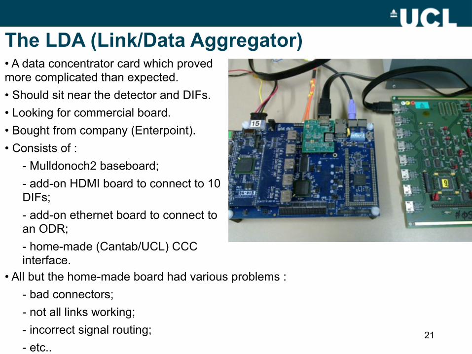
• A data concentrator card which proved more complicated than expected.• Should sit near the detector and DIFs.• Looking for commercial board.• Bought from company (Enterpoint).• Consists of :
- Mulldonoch2 baseboard;- add-on HDMI board to connect to 10 DIFs;- add-on ethernet board to connect to an ODR;- home-made (Cantab/UCL) CCC interface.
• All but the home-made board had various problems :- bad connectors;- not all links working;- incorrect signal routing;- etc..
LDA (contd)
22
• Component (now) works and is integral part of system.• For a future concentrator card, would :
- have more connections;- different connectors;- add-on boards which are standard commercial projects or own design.
• An example of commercial, off-the-shelf equipment ... which needed significant intervention from us.
The CCC (Clock and Control Card)
23
• Designed by UCL and laid out by RAL.• Clock supplied to LDA via add-on board• Functionality :
• CLOCK : machine• FAST_OUT : transfer asynchronous triggers• FAST_IN : used by DIFs to “stop acquisition”• TRAINSYNC_OUT : synchronisation of all front-end slow clocks
The ODR (Off-Detector Receiver)
24
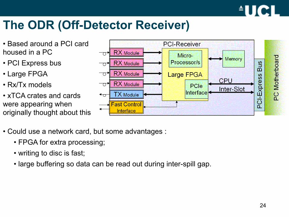
• Based around a PCI card housed in a PC• PCI Express bus• Large FPGA• Rx/Tx models• xTCA crates and cards were appearing when originally thought about this
• Could use a network card, but some advantages :• FPGA for extra processing; • writing to disc is fast;• large buffering so data can be read out during inter-spill gap.
ODR (contd)
25
• Originally thought to design but card existed already from PLDA.• Firmware task and evaluation of performance.• Comparison to xTCA systems will be valuable.• Much of the concept (and firmware) should be transportable to xTCA.
DAQ system tests
DIFs
LDA
CCC
ODR+DAQ PC
System tests
27
Have a few systems set-up (UCL, Cantab, LLR) :• DAQ PC with ODR <=> LDA <=> DIF and CCC source;• using wireshark and ‘scope to check data flow;• have successfully sent fast commands up to the DIF and received data packets back on the PC—full chain established;• have repeated with more than one DIF;• going through debug phase and using at maximum capacity, i.e. 10 DIFs, 4 LDAs;To soon be delivered to detector (calorimeter) groups for integration and detector tests.
Discussion and summary
28
Discussion of and experiences with system
29
Contrasting commercial off-the-shelf and bespoke equipment :• ODR is a good example of COTS—had all functionality needed, stable, allowed firmware development and performance testing to take precedence.• LDA was problematic—didn’t quite fit our needs and required various work-arounds.• Bespoke equipment generally worked well.• System still standards based—FPGAs, networks.Backplaneless system :• PCs are cheap and readily available.• PCs do fail and are mechanically not as convenient as crates. • Extended running periods will enlighten.
Summary
30
We have built a DAQ system for ILC calorimeter prototypes :• it basically works, needing some tweaks.• to be soon handed over to calorimeter groups for use.• we tried to go down a route of commercial equipment and standards-based. • it is sufficiently generic so as to be used for other detector systems.