2180619E April 2010 Installation and operating instructions INSTALLERS PLEASE NOTE THESE INSTRUCTIONS ARE TO BE LEFT WITH THE USER DART concentric exposed thermostatic mixer shower with fixed showerhead
Transcript
2180619E April 2010
Installation and operating instructions
Installers please note these InstructIons are to be left wIth the user
DART concentric exposed thermostatic
mixer shower with fixed showerhead
Concentric exposed thermostatic mixer shower
To check the product suitability for commercial and multiple installations, please contact Triton’s specification advisory service before installation.
Temperature adjustment range ..................................................... 11RECOMMENDED OUTLET TEMPERATURES ................................... 11
FITTING THE CONTROLS .............................................................. 12ADJUSTING THE MAXIMUM TEMPERATURE SETTING ................... 12
OPERATING THE SHOWER ............................................................ 13
Guarantee, service policy, etc. ..................................................rear cover
Concentric exposed thermostatic mixer shower
�
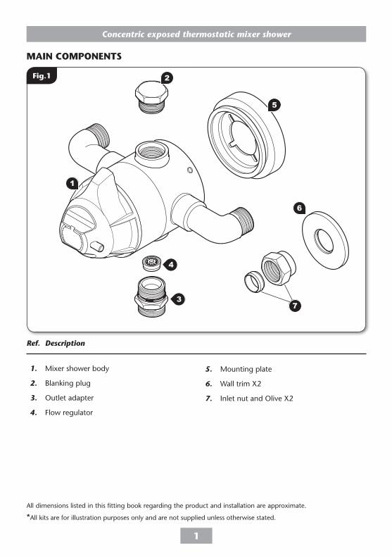
Ref. Description
1. Mixer shower body
2. Blanking plug
3. Outlet adapter
4. Flow regulator
Main componentsMAIn CoMPonents
5. Mounting plate
6. Wall trim X2
7. Inlet nut and Olive X2
7
All dimensions listed in this fitting book regarding the product and installation are approximate.
*All kits are for illustration purposes only and are not supplied unless otherwise stated.
Fig.�
5
2
6
4
3
1
Concentric exposed thermostatic mixer shower
�
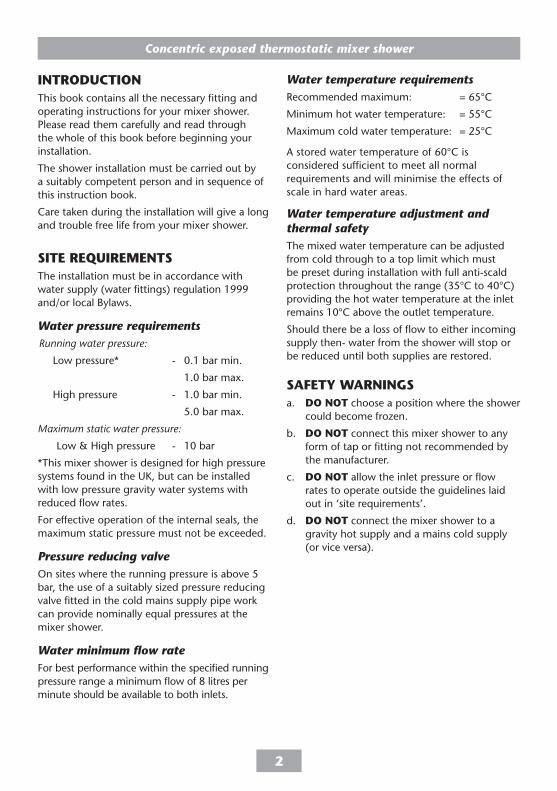
IntRoDUCtIonThis book contains all the necessary fitting and operating instructions for your mixer shower. Please read them carefully and read through the whole of this book before beginning your installation.
The shower installation must be carried out by a suitably competent person and in sequence of this instruction book.
Care taken during the installation will give a long and trouble free life from your mixer shower.
sIte ReQUIReMentsThe installation must be in accordance with water supply (water fittings) regulation 1999 and/or local Bylaws.
Water pressure requirementsRunning water pressure:
Low pressure* - 0.1 bar min.
1.0 bar max.
High pressure - 1.0 bar min.
5.0 bar max.
Maximum static water pressure:
Low & High pressure - 10 bar
*This mixer shower is designed for high pressure systems found in the UK, but can be installed with low pressure gravity water systems with reduced flow rates.
For effective operation of the internal seals, the maximum static pressure must not be exceeded.
Pressure reducing valveOn sites where the running pressure is above 5 bar, the use of a suitably sized pressure reducing valve fitted in the cold mains supply pipe work can provide nominally equal pressures at the mixer shower.
Water minimum flow rateFor best performance within the specified running pressure range a minimum flow of 8 litres per minute should be available to both inlets.
Water temperature requirementsRecommended maximum: = 65°C
Minimum hot water temperature: = 55°C
Maximum cold water temperature: = 25°C
A stored water temperature of 60°C is considered sufficient to meet all normal requirements and will minimise the effects of scale in hard water areas.
Water temperature adjustment and thermal safetyThe mixed water temperature can be adjusted from cold through to a top limit which must be preset during installation with full anti-scald protection throughout the range (35°C to 40°C) providing the hot water temperature at the inlet remains 10°C above the outlet temperature.
Should there be a loss of flow to either incoming supply then- water from the shower will stop or be reduced until both supplies are restored.
sAFetY WARnInGsa. Do not choose a position where the shower
could become frozen.
b. Do not connect this mixer shower to any form of tap or fitting not recommended by the manufacturer.
c. Do not allow the inlet pressure or flow rates to operate outside the guidelines laid out in ‘site requirements’.
d. Do not connect the mixer shower to a gravity hot supply and a mains cold supply (or vice versa).
Concentric exposed thermostatic mixer shower
�
PLEASE NOTE: Any reference made to ‘The BuildCert TMV scheme’ is for reference only. This valve is not TMV2 approved.
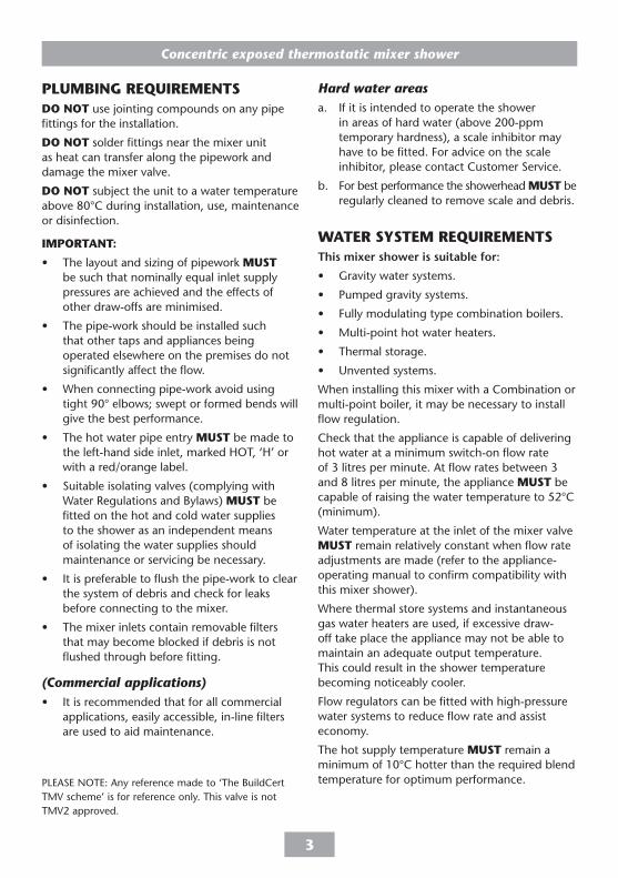
PLUMBInG ReQUIReMentsDo not use jointing compounds on any pipe fittings for the installation.
Do not solder fittings near the mixer unit as heat can transfer along the pipework and damage the mixer valve.
Do not subject the unit to a water temperature above 80°C during installation, use, maintenance or disinfection.
IMPoRtAnt:
• The layout and sizing of pipework MUst be such that nominally equal inlet supply pressures are achieved and the effects of other draw-offs are minimised.
• The pipe-work should be installed such that other taps and appliances being operated elsewhere on the premises do not significantly affect the flow.
• When connecting pipe-work avoid using tight 90° elbows; swept or formed bends will give the best performance.
• The hot water pipe entry MUst be made to the left-hand side inlet, marked HOT, ‘H’ or with a red/orange label.
• Suitable isolating valves (complying with Water Regulations and Bylaws) MUst be fitted on the hot and cold water supplies to the shower as an independent means of isolating the water supplies should maintenance or servicing be necessary.
• It is preferable to flush the pipe-work to clear the system of debris and check for leaks before connecting to the mixer.
• The mixer inlets contain removable filters that may become blocked if debris is not flushed through before fitting.
(Commercial applications)• It is recommended that for all commercial
applications, easily accessible, in-line filters are used to aid maintenance.
Hard water areasa. If it is intended to operate the shower
in areas of hard water (above 200-ppm temporary hardness), a scale inhibitor may have to be fitted. For advice on the scale inhibitor, please contact Customer Service.
b. For best performance the showerhead MUst be regularly cleaned to remove scale and debris.
WAteR sYsteM ReQUIReMentsThis mixer shower is suitable for:
• Gravity water systems.
• Pumped gravity systems.
• Fully modulating type combination boilers.
• Multi-point hot water heaters.
• Thermal storage.
• Unvented systems.
When installing this mixer with a Combination or multi-point boiler, it may be necessary to install flow regulation.
Check that the appliance is capable of delivering hot water at a minimum switch-on flow rate of 3 litres per minute. At flow rates between 3 and 8 litres per minute, the appliance MUst be capable of raising the water temperature to 52°C (minimum).
Water temperature at the inlet of the mixer valve MUst remain relatively constant when flow rate adjustments are made (refer to the appliance-operating manual to confirm compatibility with this mixer shower).
Where thermal store systems and instantaneous gas water heaters are used, if excessive draw-off take place the appliance may not be able to maintain an adequate output temperature. This could result in the shower temperature becoming noticeably cooler.
Flow regulators can be fitted with high-pressure water systems to reduce flow rate and assist economy.
The hot supply temperature MUst remain a minimum of 10°C hotter than the required blend temperature for optimum performance.
Concentric exposed thermostatic mixer shower
�
*(kits are for illustration purposes only)
tYPICAL DoMestIC InstALLAtIons
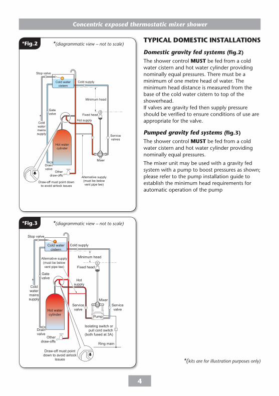
Domestic gravity fed systems (fig.�)
The shower control MUst be fed from a cold water cistern and hot water cylinder providing nominally equal pressures. There must be a minimum of one metre head of water. The minimum head distance is measured from the base of the cold water cistern to top of the showerhead. If valves are gravity fed then supply pressure should be verified to ensure conditions of use are appropriate for the valve.
Pumped gravity fed systems (fig.�)
The shower control MUst be fed from a cold water cistern and hot water cylinder providing nominally equal pressures.
The mixer unit may be used with a gravity fed system with a pump to boost pressures as shown; please refer to the pump installation guide to establish the minimum head requirements for automatic operation of the pump
Hot watercylinder
Cold supply
Hot supply
Alternative supply(must be belowvent pipe tee)
Coldwatermainssupply
Drainvalve
Gatevalve
Stop valve
Cold watercistern
Minimum head
Otherdraw-offs
Draw-off must point downto avoid airlock issues
Servicevalves
Mixer
Fixed head
Hot watercylinder
Mixer
Cold supply
Hotsupply
Alternative supply(must be belowvent pipe tee)
Coldwatermainssupply
Drainvalve
Gatevalve
Stop valve
Cold watercistern
Minimum head
Otherdraw-offs
Draw-off must pointdown to avoid airlock
issues
Ring main
Isolating switch orpull cord switch
(both fused at 3A)
Servicevalve
Servicevalve
Pump
Fixed head
*Fig.� *(diagrammatic view – not to scale)
*Fig.� *(diagrammatic view – not to scale)
Concentric exposed thermostatic mixer shower
�
*(kits are for illustration purposes only)
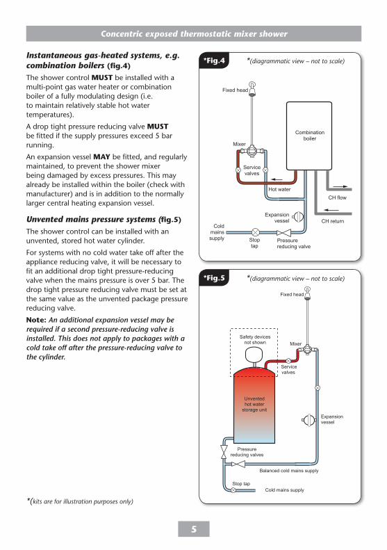
Instantaneous gas-heated systems, e.g. combination boilers (fig.�)
The shower control MUst be installed with a multi-point gas water heater or combination boiler of a fully modulating design (i.e. to maintain relatively stable hot water temperatures).
A drop tight pressure reducing valve MUst be fitted if the supply pressures exceed 5 bar running.
An expansion vessel MAY be fitted, and regularly maintained, to prevent the shower mixer being damaged by excess pressures. This may already be installed within the boiler (check with manufacturer) and is in addition to the normally larger central heating expansion vessel.
Unvented mains pressure systems (fig.�)
The shower control can be installed with an unvented, stored hot water cylinder.
For systems with no cold water take off after the appliance reducing valve, it will be necessary to fit an additional drop tight pressure-reducing valve when the mains pressure is over 5 bar. The drop tight pressure reducing valve must be set at the same value as the unvented package pressure reducing valve.
note: An additional expansion vessel may be required if a second pressure-reducing valve is installed. This does not apply to packages with a cold take off after the pressure-reducing valve to the cylinder.
Fixed head
Mixer
Servicevalves
Balanced cold mains supply
Cold mains supply
Expansionvessel
Pressurereducing valves
Stop tap
Unventedhot water
storage unit
Safety devicesnot shown
Fixed head
CH flow
Coldmainssupply
Hot water
CH return
Servicevalves
Mixer
Stoptap
Expansionvessel
Pressurereducing valve
Combinationboiler
*Fig.� *(diagrammatic view – not to scale)
*Fig.� *(diagrammatic view – not to scale)
Concentric exposed thermostatic mixer shower
�
*(kits are for illustration purposes only)
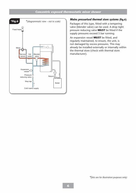
Mains pressurised thermal store systems (fig.�)
Packages of this type, fitted with a tempering valve (blender valve) can be used. A drop tight pressure reducing valve MUst be fitted if the supply pressures exceed 5 bar running.
An expansion vessel MUst be fitted, and regularly maintained, to ensure, the unit, is not damaged by excess pressures. This may already be installed externally or internally within the thermal store (check with thermal store manufacturer).
Fixed head
Mixer
Blendervalve
Flow
Cold mains supply
Hotwater
Stop tap
Expansionvessel
Pressurereducing valve Return
Servicevalves
Boiler
*Fig.� *(diagrammatic view – not to scale)
Concentric exposed thermostatic mixer shower
�
*(kits are for illustration purposes only)
Approx30 - 35mm
Approx
150mm
InstALLAtIon
Preparing the mixer valveCheck the contents to make sure all parts are present.
Before starting the mixer installation, make sure all the openings on the valve are carefully covered to stop ingress of any debris, etc. while routing the supply pipework.
The shower valve is suitable for exposed installation onto solid wall, a stud partition wall, dry lined wall or fixing to a laminate cubicle or panel.
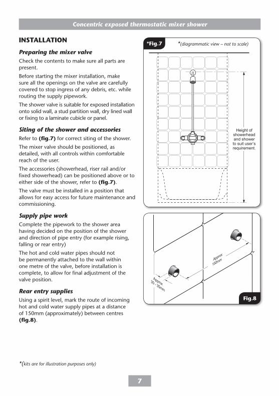
Siting of the shower and accessoriesRefer to (fig.�) for correct siting of the shower.
The mixer valve should be positioned, as detailed, with all controls within comfortable reach of the user.
The accessories (showerhead, riser rail and/or fixed showerhead) can be positioned above or to either side of the shower, refer to (fig.�).
The valve must be installed in a position that allows for easy access for future maintenance and commissioning.
Supply pipe workComplete the pipework to the shower area having decided on the position of the shower and direction of pipe entry (for example rising, falling or rear entry)
The hot and cold water pipes should not be permanently attached to the wall within one metre of the valve, before installation is complete, to allow for final adjustment of the valve position.
Rear entry suppliesUsing a spirit level, mark the route of incoming hot and cold water supply pipes at a distance of 150mm (approximately) between centres (fig.8).
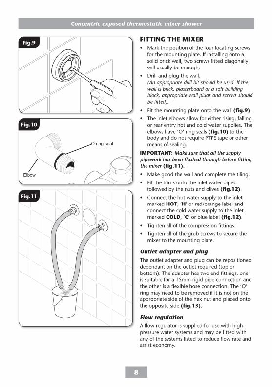
FIttInG tHe MIXeR• Mark the position of the four locating screws
for the mounting plate. If installing onto a solid brick wall, two screws fitted diagonally will usually be enough.
• Drill and plug the wall. (An appropriate drill bit should be used. If the wall is brick, plasterboard or a soft building block, appropriate wall plugs and screws should be fitted).
• Fit the mounting plate onto the wall (fig.9).
• The inlet elbows allow for either rising, falling or rear entry hot and cold water supplies. The elbows have ‘O’ ring seals (fig.�0) to the body and do not require PTFE tape or other means of sealing.
IMPoRtAnt: Make sure that all the supply pipework has been flushed through before fitting the mixer (fig.��).
• Make good the wall and complete the tiling.
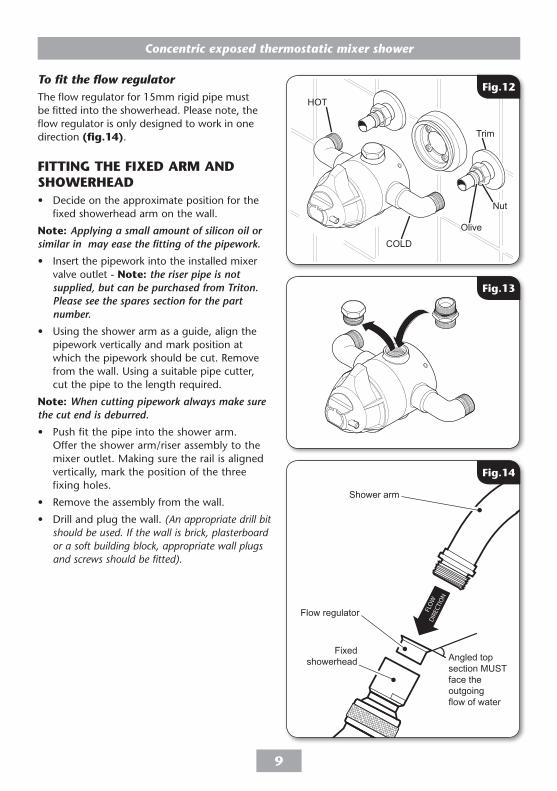
• Fit the trims onto the inlet water pipes followed by the nuts and olives (fig.��).
• Connect the hot water supply to the inlet marked Hot, ‘H’ or red/orange label and connect the cold water supply to the inlet marked CoLD, ‘C’ or blue label (fig.��).
• Tighten all of the compression fittings.
• Tighten all of the grub screws to secure the mixer to the mounting plate.
Outlet adapter and plugThe outlet adapter and plug can be repositioned dependant on the outlet required (top or bottom). The adapter has two end fittings, one is suitable for a 15mm rigid pipe connection and the other is a flexible hose connection. The ‘O’ ring may need to be removed if it is not on the appropriate side of the hex nut and placed onto the opposite side (fig.��).
Flow regulationA flow regulator is supplied for use with high-pressure water systems and may be fitted with any of the systems listed to reduce flow rate and assist economy.
Fig.��
Fig.�0
Fig.9
Concentric exposed thermostatic mixer shower
9
To fit the flow regulatorThe flow regulator for 15mm rigid pipe must be fitted into the showerhead. Please note, the flow regulator is only designed to work in one direction (fig.��).
FIttInG tHe FIXeD ARM AnD sHoWeRHeAD• Decide on the approximate position for the
fixed showerhead arm on the wall.
note: Applying a small amount of silicon oil or similar in may ease the fitting of the pipework.
• Insert the pipework into the installed mixer valve outlet - note: the riser pipe is not supplied, but can be purchased from Triton. Please see the spares section for the part number.
• Using the shower arm as a guide, align the pipework vertically and mark position at which the pipework should be cut. Remove from the wall. Using a suitable pipe cutter, cut the pipe to the length required.
note: When cutting pipework always make sure the cut end is deburred.
• Push fit the pipe into the shower arm. Offer the shower arm/riser assembly to the mixer outlet. Making sure the rail is aligned vertically, mark the position of the three fixing holes.
• Remove the assembly from the wall.
• Drill and plug the wall. (An appropriate drill bit should be used. If the wall is brick, plasterboard or a soft building block, appropriate wall plugs and screws should be fitted).
HOT
COLD
Trim
Nut
Olive
Fig.��
Fig.��
Flow regulator
Shower arm
Angled top section MUST face the outgoingflow of water
Fig.��
Fixed showerhead
Concentric exposed thermostatic mixer shower
�0
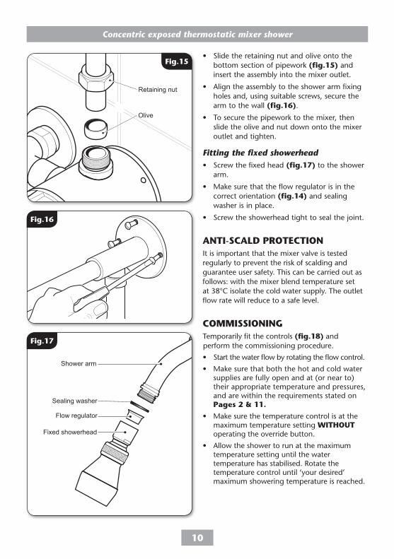
• Slide the retaining nut and olive onto the bottom section of pipework (fig.��) and insert the assembly into the mixer outlet.
• Align the assembly to the shower arm fixing holes and, using suitable screws, secure the arm to the wall (fig.��).
• To secure the pipework to the mixer, then slide the olive and nut down onto the mixer outlet and tighten.
Fitting the fixed showerhead• Screw the fixed head (fig.��) to the shower
arm.
• Make sure that the flow regulator is in the correct orientation (fig.��) and sealing washer is in place.
• Screw the showerhead tight to seal the joint.
AntI-sCALD PRoteCtIon It is important that the mixer valve is tested regularly to prevent the risk of scalding and guarantee user safety. This can be carried out as follows: with the mixer blend temperature set at 38°C isolate the cold water supply. The outlet flow rate will reduce to a safe level.
CoMMIssIonInGTemporarily fit the controls (fig.�8) and perform the commissioning procedure.
• Start the water flow by rotating the flow control.
• Make sure that both the hot and cold water supplies are fully open and at (or near to) their appropriate temperature and pressures, and are within the requirements stated on Pages � & ��.
• Make sure the temperature control is at the maximum temperature setting WItHoUt operating the override button.
• Allow the shower to run at the maximum temperature setting until the water temperature has stabilised. Rotate the temperature control until ‘your desired’ maximum showering temperature is reached.
T00174
Retaining nut
Olive
Fig.��
Fig.��
Fig.��
Flow regulator
Shower arm
Fixed showerhead
Sealing washer
Concentric exposed thermostatic mixer shower
��
note: If your desired temperature is above the maximum temperature stop limit, please see ‘ADJUSTING THE MAXIMUM TEMPERATURE STOP SETTING’ on Page ��.
• A final temperature check sHoULD be made on-site to guarantee user safety, and that the mixer falls within recommended ‘maximum mixed water outlet temperatures’ - as stated below.
LeAK testInGDirect the outlet of the mixer to waste. Open the isolating valves to the shower and check for leaks. Remedy any leaks found.
Temperature adjustment rangeThe mixer has a temperature stop to prevent accidental rotation to higher temperatures. This is adjustable to provide a maximum temperature of 35°C - 45°C and should be checked on site to guarantee user safety.
The mixed water temperature can be adjusted from cold through to a top limit (which can be pre-set during installation – factory set at approximately 38°C) with full anti-scald protection throughout the range.
Recommended outlet temperaturesthe BuildCert tMV scheme recommends the following set maximum mixed water outlet temperatures for use in all premises:
44°C - for bath fill but see notes below.
41°C - for showers.
41°C - for washbasins.
38°C - for bidets.
The mixed water temperatures must never exceed ��°C at terminal fitting.
The British Burns Association recommends �� to ��.�°C as a comfortable bathing temperature for children. In premises covered by the Care Standards Act 2000, the maximum mixed water outlet temperature is ��°C.
Fig.�8
2mm above 3 o’clock
a.
b.
c.
3 o’clock position
12 o’clock position
3 o’clock position
Retaining grub screw
Washer A
Washer B
Flow control
Temperature control
Concentric exposed thermostatic mixer shower
��
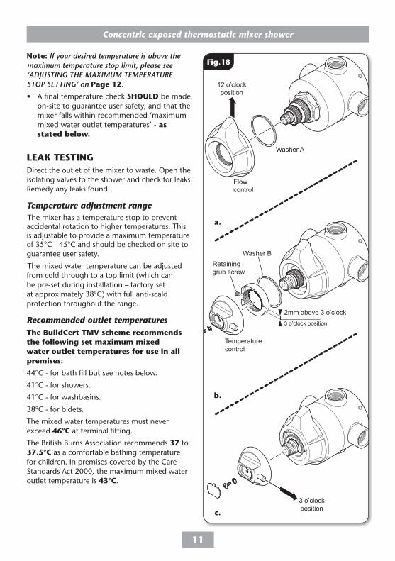
FIttInG tHe ContRoLsThe mixer valve is supplied without the controls fitted. Once a comfortable showering temperature has been established fit them as shown in (fig.�8).
IMPoRtAnt: DO NOT over tighten fitting screws.
• (fig.�8-a) Fit washer A and then the flow control lever so that it is in the 12 o’clock position.
• (fig.�8-b) Fit the washer B and then the maximum temperature stop.
• The end of the thin outer raised edge should be around 2mm above the 3 o’clock position with the grub screw fitting positioned on the left hand side. Once the maximum temperature stop in place, tighten the retaining grub screw.
• (fig.�8-c) Fit the temperature control, making sure the maximum temperature stop pin is as close to the flat edge of the temperature stop as possible.
• Secure the temperature knob in place with the retaining screw and fit the end trim.
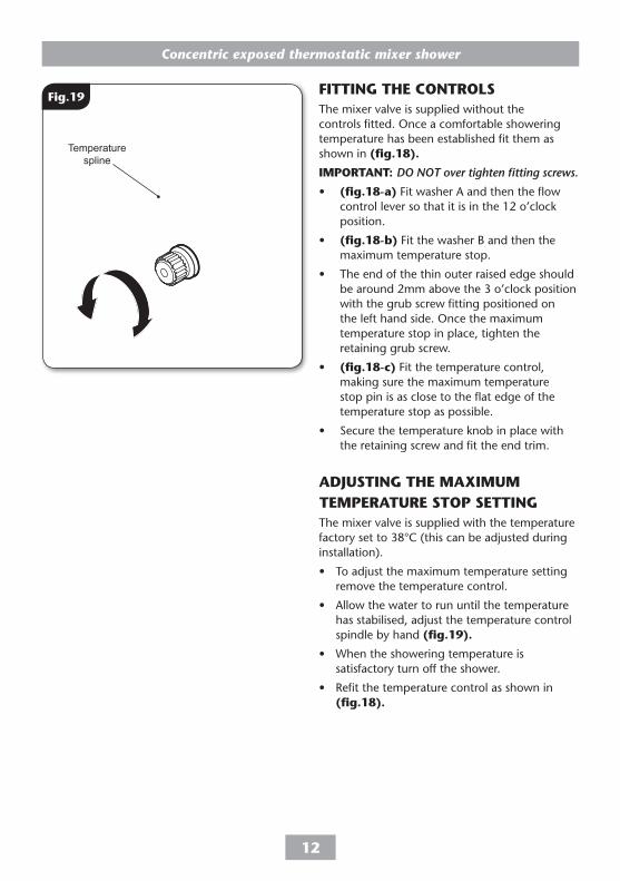
ADJUstInG tHe MAXIMUM teMPeRAtURe stoP settInGThe mixer valve is supplied with the temperature factory set to 38°C (this can be adjusted during installation).
• To adjust the maximum temperature setting remove the temperature control.
• Allow the water to run until the temperature has stabilised, adjust the temperature control spindle by hand (fig.�9).
• When the showering temperature is satisfactory turn off the shower.
• Refit the temperature control as shown in (fig.�8).
Fig.�9
Temperature spline
Concentric exposed thermostatic mixer shower
��
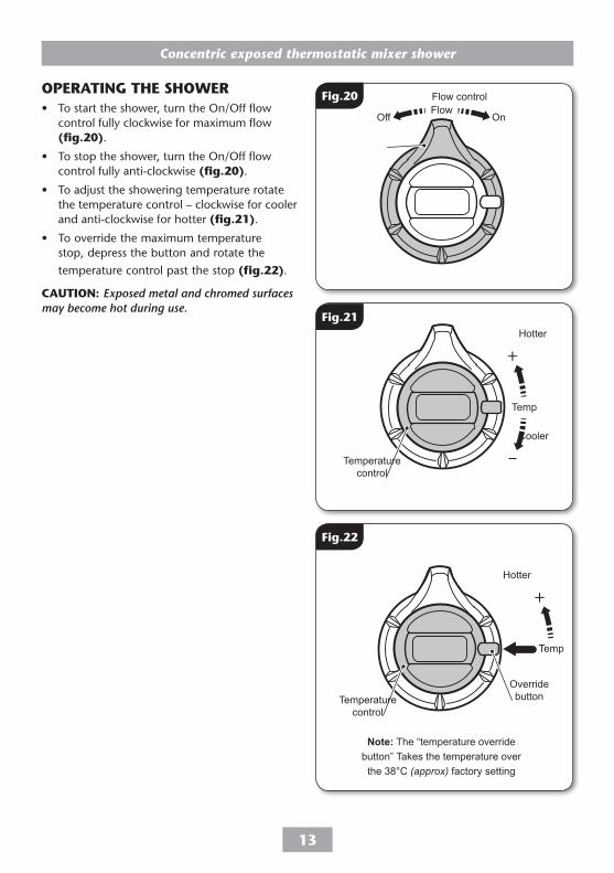
oPeRAtInG tHe sHoWeR• To start the shower, turn the On/Off flow
control fully clockwise for maximum flow (fig.�0).
• To stop the shower, turn the On/Off flow control fully anti-clockwise (fig.�0).
• To adjust the showering temperature rotate the temperature control – clockwise for cooler and anti-clockwise for hotter (fig.��).
• To override the maximum temperature stop, depress the button and rotate the
temperature control past the stop (fig.��).
CAUtIon: Exposed metal and chromed surfaces may become hot during use.
OnOff
Temp
Temp
Flow
OnOff
Temp
Temp
Flow
Fig.�0
Fig.��
OnOff
Temp
Temp
Flow
Flow control
Temperature control
Hotter
Cooler
Temperature control
Fig.��
Note: The “temperature override button” Takes the temperature over
the 38°C (approx) factory setting
Hotter
Override button
Concentric exposed thermostatic mixer shower
��
ø72m
m
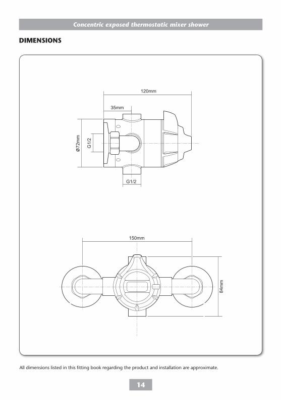
All dimensions listed in this fitting book regarding the product and installation are approximate.
DIMensIons
150mm
84m
m
G1/
2
35mm
120mm
G1/2
Concentric exposed thermostatic mixer shower
��
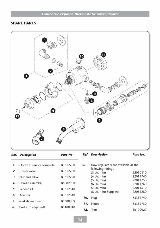
sPARe PARts
Ref. Description Part No.
1. Elbow assembly complete: 83312780
2. Check valve 83312760
3. Nut and Olive 83312790
4. Handle assembly 86002900
5. Service kit 83312810
6. Adapter 83312840
7. Fixed showerhead 88600009
8. Short arm (exposed) 88400010
Ref. Description Part No.
9. Flow regulators are available at the following ratings: (3 Ltr/min) 22010310 (4 Ltr/min) 22011740 (5 Ltr/min) 22011750 (6 Ltr/min) 22011760 (7 Ltr/min) 22011610 (8 Ltr/min) Supplied 22011280
10. Plug 83312740
11. Plinth 83312750
12. Trim 86100027
1
3
2
4
5
6
10 11
9
7
8
12
Concentric exposed thermostatic mixer shower
��
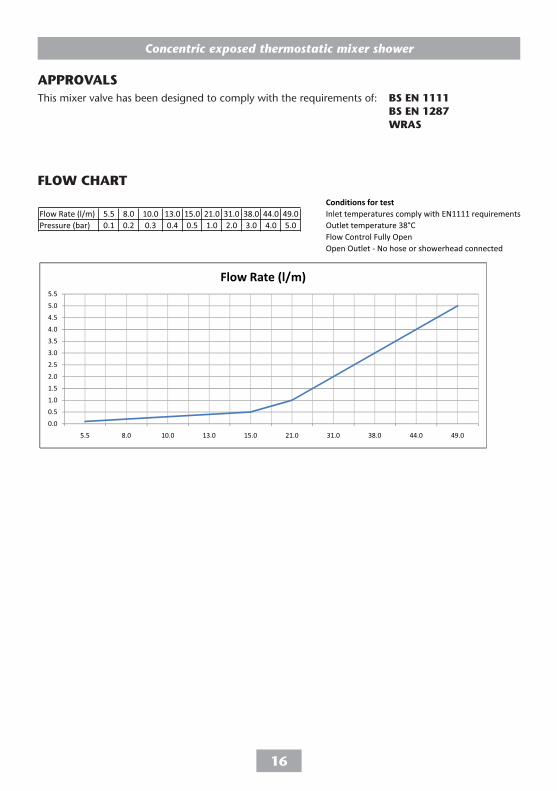
APPRoVALsThis mixer valve has been designed to comply with the requirements of: Bs en ���� Bs en ��8� WRAs
FLoW CHARt
Concentric exposed thermostatic mixer shower
��
MAIntenAnCeThe following maintenance procedure must be carried out for commercial and health care premises, but is not necessarily required for domestic installations.
Maintenance of the unit is required to give continued performance after installation and that it continues to provide scald prevention.
note: A thermostatic mixing valve in need of maintenance can be undetectable in normal use and only becomes apparent when a disruption occurs in the hot or cold water supply temperatures or pressures.
The frequency of routine maintenance of the internal of the valve will depend mainly on the water supply condition. Experience of local conditions will dictate the intervals for inspection and in-service testing. Guidance has been given below which can be adjusted for local requirements.
a) Initially check the filters for debris once every three months and clean if necessary.
b) Perform a thermal shut off test every three months, and check the maximum temperature setting. See the ‘Commissioning’ section for the details of this test and readjustment of the maximum temperature setting if required.
c) If the maximum water temperature varies by more than 2°C from the commissioned setting then carry out the following checks
• Check the isolating valves are fully open.
• Check the internal surface for scaling.
If the body requires descaling then it should be removed from the pipework to carry this work out (all rubber parts MUst be removed before descaling).
• Check the function of the non-return valves.
The non-return valves (NRVs) prevent cross-flow between hot and cold supplies under unequal pressure conditions. They are designed for long life with no maintenance.
If these checks do not highlight the reason for the temperature variation, then internal components will require replacement - please see the spare parts list.
WARnInG!
Do not use ‘powerful’ abrasive or solvent cleaning fluids when cleaning the shower as they may damage the fittings.
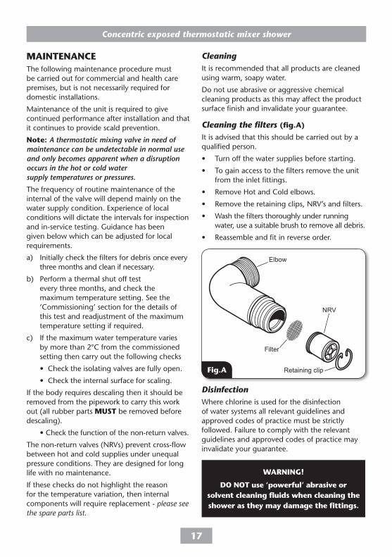
Elbow
Filter
NRV
Retaining clip
CleaningIt is recommended that all products are cleaned using warm, soapy water.
Do not use abrasive or aggressive chemical cleaning products as this may affect the product surface finish and invalidate your guarantee.
Cleaning the filters (fig.A)
It is advised that this should be carried out by a qualified person.
• Turn off the water supplies before starting.
• To gain access to the filters remove the unit from the inlet fittings.
• Remove Hot and Cold elbows.
• Remove the retaining clips, NRV’s and filters.
• Wash the filters thoroughly under running water, use a suitable brush to remove all debris.
• Reassemble and fit in reverse order.
DisinfectionWhere chlorine is used for the disinfection of water systems all relevant guidelines and approved codes of practice must be strictly followed. Failure to comply with the relevant guidelines and approved codes of practice may invalidate your guarantee.
Fig.A
Concentric exposed thermostatic mixer shower
�8
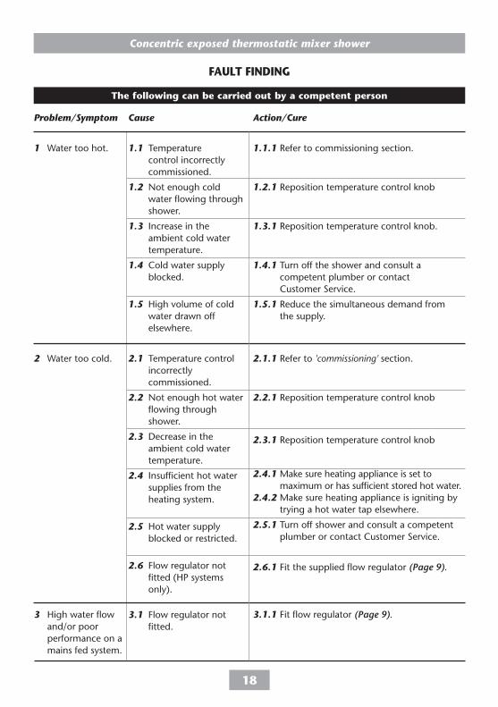
the following can be carried out by a competent person
FAULt FInDInG
1 Water too hot.
2 Water too cold.
3 High water flow and/or poor performance on a mains fed system.
1.1 Temperature control incorrectly commissioned.
1.2 Not enough cold water flowing through shower.
1.3 Increase in the ambient cold water temperature.
1.4 Cold water supply blocked.
1.5 High volume of cold water drawn off elsewhere.
2.1 Temperature control incorrectly commissioned.
2.2 Not enough hot water flowing through shower.
2.3 Decrease in the ambient cold water temperature.
2.4 Insufficient hot water supplies from the heating system.
2.5 Hot water supply blocked or restricted.
2.6 Flow regulator not fitted (HP systems only).
3.1 Flow regulator not fitted.
1.1.1 Refer to commissioning section.
1.2.1 Reposition temperature control knob
1.3.1 Reposition temperature control knob.
1.4.1 Turn off the shower and consult a competent plumber or contact Customer Service.
1.5.1 Reduce the simultaneous demand from the supply.
2.1.1 Refer to 'commissioning' section.
2.2.1 Reposition temperature control knob
2.3.1 Reposition temperature control knob
2.4.1 Make sure heating appliance is set to maximum or has sufficient stored hot water.
2.4.2 Make sure heating appliance is igniting by trying a hot water tap elsewhere.
2.5.1 Turn off shower and consult a competent plumber or contact Customer Service.
2.6.1 Fit the supplied flow regulator (Page 9).
3.1.1 Fit flow regulator (Page 9).
Problem/Symptom Cause Action/Cure
Concentric exposed thermostatic mixer shower
�9
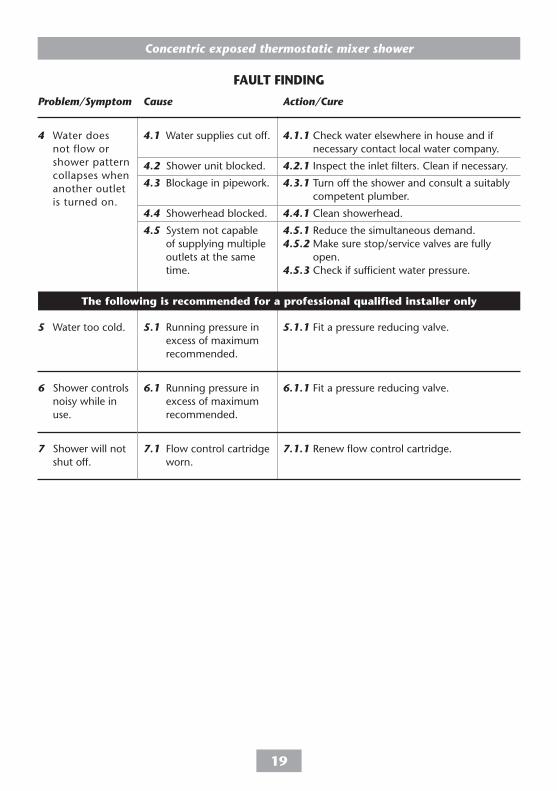
4.1 Water supplies cut off.
4.2 Shower unit blocked.
4.3 Blockage in pipework.
4.4 Showerhead blocked.
4.5 System not capable of supplying multiple outlets at the same time.
5.1 Running pressure in excess of maximum recommended.
6.1 Running pressure in excess of maximum recommended.
7.1 Flow control cartridge worn.
4.1.1 Check water elsewhere in house and if necessary contact local water company.
4.2.1 Inspect the inlet filters. Clean if necessary.
4.3.1 Turn off the shower and consult a suitably competent plumber.
4.4.1 Clean showerhead.
4.5.1 Reduce the simultaneous demand.4.5.2 Make sure stop/service valves are fully
open.4.5.3 Check if sufficient water pressure.
5.1.1 Fit a pressure reducing valve.
6.1.1 Fit a pressure reducing valve.
7.1.1 Renew flow control cartridge.
4 Water does not flow or shower pattern collapses when another outlet is turned on.
5 Water too cold.
6 Shower controls noisy while in use.
7 Shower will not shut off.
FAULt FInDInG
Problem/Symptom Cause Action/Cure
the following is recommended for a professional qualified installer only
UK SERVICE POLICYIn the event of a product fault or complaint occurring, the following procedure should be followed:1. Telephone Customer Service on 0844 980 0750 having available,
your details including post code, the model number and power rating of the product, together with the date of purchase.
2. Based on information given over the telephone, a Triton Customer Service Advisor will attempt to diagnose the fault and confirm whether a site visit from a qualified service engineer is required.
3. All products attended to by a Triton service engineer must be installed in full accordance with the Triton installation guide applicable to the product. (Every product pack contains an installation guide, however, they can also be bought via our Customer Service Spares Department).
4. Our engineer will require local parking and if a permit is required this must be available to the engineer on arrival at the call.
5. It is essential that you or an appointed representative (who must be over 18 years of age) is present for the duration of the service engineer's visit. If the product is in guarantee you must produce proof of purchase.
6. Where a call under the terms of guarantee has been booked and the failure is not product related (i.e. scaling and furring, incorrect water pressure, pressure relief device operation or electrical/plumbing installation fault) a charge will be made. A charge will also be issued if nobody is at home when the service engineer calls or adequate parking/permit is not available.
7. If the product is no longer covered by the guarantee an up front fixed fee will be charged before the site visit.
8. Should proof of purchase not be available on an “in-guarantee” call, or should the service engineer find that the product is no longer under guarantee, the engineer will charge the same fixed price and the customer will be expected to pay the engineer before he leaves. If payment is not made on the day an administration charge will be added to the fixed charge.
9. If a debt is outstanding from a previous visit, or from any other Triton purchase. Triton reserves the right to withhold service until the debt has been settled.
10. Triton takes the health, safety and wellbeing of its employees very seriously and expects customers to treat all staff members with respect. Should any employee feel threatened or receive abuse, either verbally or physically, Triton reserves the right to withhold service and will support the employee with a legal prosecution.
Replacement Parts PolicyAvailability: It is the policy of the manufacturer to maintain parts availability for the duration of production and a period of five years thereafter, in accordance with industry standards.Spare parts are available via our website, www.tritonshowers.co.uk, or by telephoning Triton Customer Service Spares Department. Payment should be made by credit/debit card (excluding American Express or Diners Card).Payment can also be made by pre-payment of a pro forma invoice by cheque or money order.
TRITOn STandaRd GUaRanTEETriton guarantee this product against all mechanical defects arising from faulty workmanship or materials for a period of five years for domestic use only, from the date of purchase, provided that it has been installed by a competent person in full accordance with the fitting instructions.
Any part found to be defective during this guarantee period we undertake to repair or replace at our option without charge so long as it has been properly maintained and operated in accordance with the operating instructions, and has not been subject to misuse or damage.
This product must not be taken apart, modified or repaired except by a person authorised by Triton. This guarantee applies only to products installed within the United Kingdom and does not apply to products used commercially. This guarantee does not affect your statutory rights.
What is not covered:
1. Breakdown due to: a) use other than domestic use by you or your resident family; b) wilful act or neglect; c) any malfunction resulting from the incorrect use or quality of electricity, gas or water or incorrect setting of controls; d) failure to install in accordance with this installation guide.
2. Repair costs for damage caused by foreign objects or substances.
3. Total loss of the product due to non-availability of parts.
4. Compensation for loss of use of the product or consequential loss of any kind.
5. Call out charges where no fault has been found with the appliance.
6. Call out charges where the water supply cannot be isolated, this includes consequential losses arising from unserviceable supply valves.
7. The cost of repair or replacement of pressure relief devices, showerheads, hoses, riser rails and/or wall brackets, isolating switches, electrical cable, fuses and/or circuit breakers or any other accessories installed at the same time.
8. The cost of routine maintenance, adjustments, overhaul modifications or loss or damage arising therefrom, including the cost of repairing damage, breakdown, malfunction caused by corrosion, furring, pipe scaling, limescale, system debris or frost.