INSTALLERS PLEASE NOTE THESE INSTRUCTIONS ARE TO BE LEFT WITH THE USER 2180600B March 2007 Installation and operating instructions Dart Eco concentric thermostatic mixer shower ECO STATEMENT This product has been fitted with a flow regulator to deliver a maximum flow rate of 9 litres per minute.
Transcript
Installers please note these InstructIons are to be left wIth the user
2180600B March 2007
Installation and operating
instructions
Dart Ecoconcentric
thermostatic mixer shower
Eco StatEmEnt
this product has been fitted with a flow regulator to deliver a maximum flow
rate of 9 litres per minute.
Eco concentric mixer
To check the product suitability for commercial and multiple installations, please contact Triton’s specification advisory service before installation. Telephone: +44 (0) 87 0067 3767 Facsimile: +44 (0) 87 0067 3334 E mail: [email protected]
ContEnts Page
Introduction 1
Safety warnings 1
Main components 2
Site requirements 3
Typical suitable installations 4
Getting started 6
Siting of the shower 6
Installation 6
Option 1: Exposed fitting 8
Option 2: Built-in fitting 10
Bulkhead assembly 14
Commissioning 15
Adjusting the maximum temperature setting 16
Operation 17
Cleaning 17
Adjusting the showerhead 18
Cleaning the showerhead 19
Spare parts 20
Fault finding 22
Service policy, guarantee, etc. rear cover
Eco concentric mixer
�
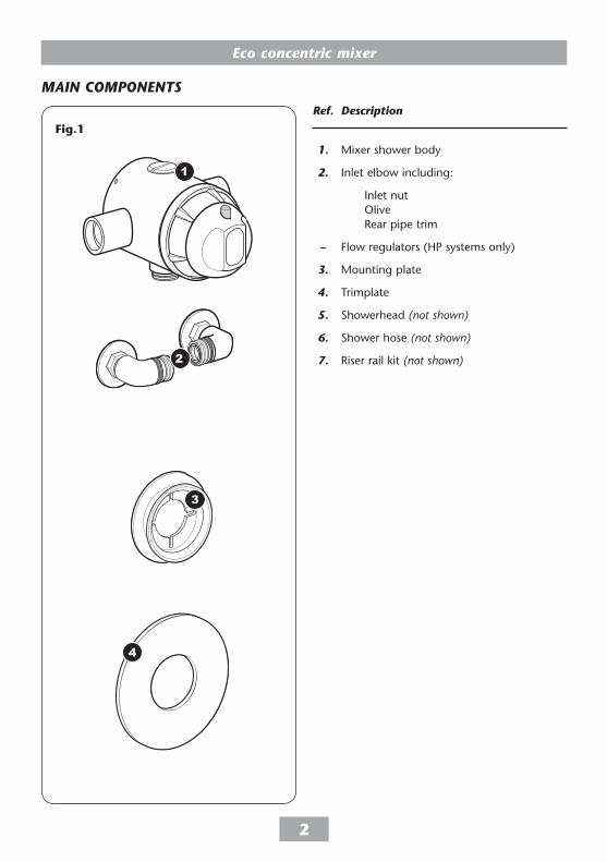
IntroDuCtIonThis book contains all the necessary fitting and operating instructions for your Triton Eco concentric mixer shower. Please read them carefully.
Read through the whole of this book before beginning your installation.
The shower installation must be carried out by a suitably competent person and in sequence of this instruction book.
Care taken during the installation will give a long and trouble free life from your shower.
For best performance within the specified running pressure range a minimum flow of 8 litres per minute should be available to both inlets.
The mixer shower MuST nOT be subjected to water temperatures above 80°C.
This mixer shower is designed for use with traditional low pressure ‘gravity’ water systems, using a cold water cistern and hot water cylinder as well as for the higher pressure systems found in the uK up to a maximum of 5 bar running pressure.
This mixer shower is suitable for fully modulating type combination boilers and multi-point hot water heaters. It is also suitable for thermal storage, unvented systems and pumped gravity systems.
Important: Before installing with a gas instantaneous water heater, make sure it is capable of delivering hot water at a minimum switch-on flow rate of 3 litres per minute. At flow rates between 3 and 8 litres per minute, the appliance must be capable of raising the water temperature to a minimum of 52°C. Water temperature at the mixer inlet must remain relatively constant when flow rate adjustments are made (refer to the water heater operating manual to confirm compatibility with this mixer shower).
This mixer shower is supplied with an integral large area filter in each inlet elbow. Inlet connections are by compression fittings for 15 mm copper pipe.
safEty warnIngsa. Layout and sizing of pipework MuST be such
that when other services are used, pressures at the shower control inlets DO nOT fall below the recommended minimum.
b. Do not choose a position where the shower could become frozen.
c. Do not connect this mixer shower to any form of tap or fitting not recommended by the manufacturer.
d. The showerhead MuST be regularly cleaned to remove scale and debris.
e. Conveniently situated isolating valves in each inlet supply MuST be fitted as an independent method of isolating the shower should maintenance or servicing be necessary.
f. If it is intended to operate the shower in areas of hard water (above 200 ppm temporary hardness), a scale inhibitor may have to be fitted. For advice on the Triton scale inhibitor, please contact Customer Service.
g. Do not operate the shower outside the guidelines as laid out in ‘site requirements’.
Replacement parts can be ordered from Triton Customer Service. See ‘spare parts’ for details and part numbers.
Due to continuous improvement and updating, specification may be altered without prior notice.
Eco concentric mixer
�
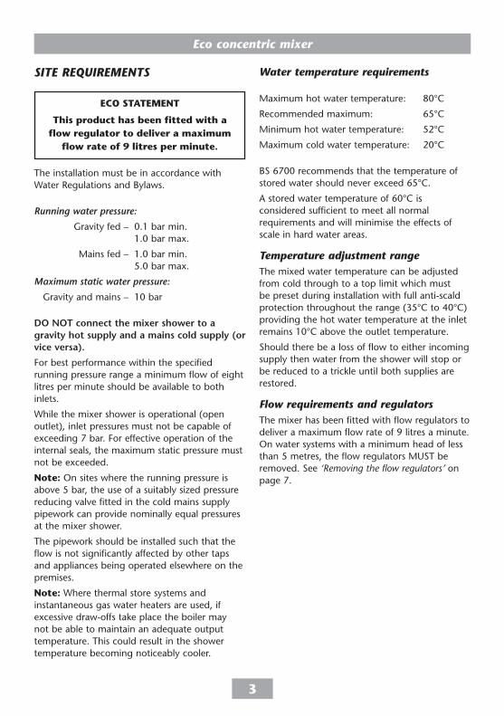
MaIn CoMPonEnts
ref. Description
1. Mixer shower body
2. Inlet elbow including:
Inlet nut Olive Rear pipe trim
– Flow regulators (HP systems only)
3. Mounting plate
4. Trimplate
5. Showerhead (not shown)
6. Shower hose (not shown)
7. Riser rail kit (not shown)
Fig.�
1
2
3
4
Eco concentric mixer
�
sItE rEquIrEMEnts
The installation must be in accordance with Water Regulations and Bylaws.
Running water pressure:
Gravity fed – 0.1 bar min. 1.0 bar max.
Mains fed – 1.0 bar min. 5.0 bar max.
Maximum static water pressure:
Gravity and mains – 10 bar
Do not connect the mixer shower to a gravity hot supply and a mains cold supply (or vice versa).
For best performance within the specified running pressure range a minimum flow of eight litres per minute should be available to both inlets.
While the mixer shower is operational (open outlet), inlet pressures must not be capable of exceeding 7 bar. For effective operation of the internal seals, the maximum static pressure must not be exceeded.
note: On sites where the running pressure is above 5 bar, the use of a suitably sized pressure reducing valve fitted in the cold mains supply pipework can provide nominally equal pressures at the mixer shower.
The pipework should be installed such that the flow is not significantly affected by other taps and appliances being operated elsewhere on the premises.
note: Where thermal store systems and instantaneous gas water heaters are used, if excessive draw-offs take place the boiler may not be able to maintain an adequate output temperature. This could result in the shower temperature becoming noticeably cooler.
water temperature requirements
Maximum hot water temperature: 80°C
Recommended maximum: 65°C
Minimum hot water temperature: 52°C
Maximum cold water temperature: 20°C
BS 6700 recommends that the temperature of stored water should never exceed 65°C.
A stored water temperature of 60°C is considered sufficient to meet all normal requirements and will minimise the effects of scale in hard water areas.
temperature adjustment rangeThe mixed water temperature can be adjusted from cold through to a top limit which must be preset during installation with full anti-scald protection throughout the range (35°C to 40°C) providing the hot water temperature at the inlet remains 10°C above the outlet temperature.
Should there be a loss of flow to either incoming supply then water from the shower will stop or be reduced to a trickle until both supplies are restored.
flow requirements and regulatorsThe mixer has been fitted with flow regulators to deliver a maximum flow rate of 9 litres a minute. On water systems with a minimum head of less than 5 metres, the flow regulators MuST be removed. See ‘Removing the flow regulators’ on page 7.
Eco StatEmEnt
this product has been fitted with a flow regulator to deliver a maximum
flow rate of 9 litres per minute.
Eco concentric mixer
�
tyPICal suItablE InstallatIons
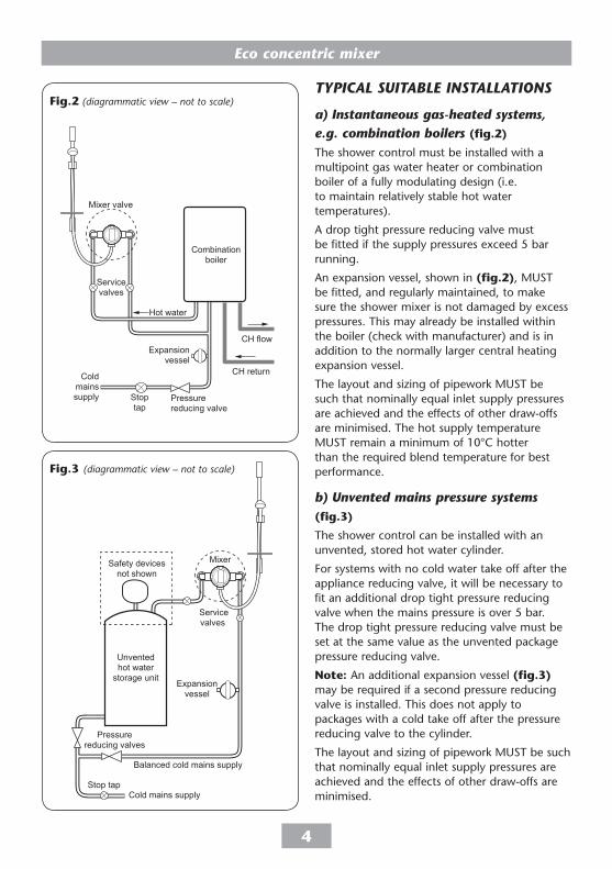
a) Instantaneous gas-heated systems,e.g. combination boilers (fig.�)
The shower control must be installed with a multipoint gas water heater or combination boiler of a fully modulating design (i.e. to maintain relatively stable hot water temperatures).
A drop tight pressure reducing valve must be fitted if the supply pressures exceed 5 bar running.
An expansion vessel, shown in (fig.�), MuST be fitted, and regularly maintained, to make sure the shower mixer is not damaged by excess pressures. This may already be installed within the boiler (check with manufacturer) and is in addition to the normally larger central heating expansion vessel.
The layout and sizing of pipework MuST be such that nominally equal inlet supply pressures are achieved and the effects of other draw-offs are minimised. The hot supply temperature MuST remain a minimum of 10°C hotter than the required blend temperature for best performance.
b) unvented mains pressure systems (fig.�)
The shower control can be installed with an unvented, stored hot water cylinder.
For systems with no cold water take off after the appliance reducing valve, it will be necessary to fit an additional drop tight pressure reducing valve when the mains pressure is over 5 bar. The drop tight pressure reducing valve must be set at the same value as the unvented package pressure reducing valve.
note: An additional expansion vessel (fig.�) may be required if a second pressure reducing valve is installed. This does not apply to packages with a cold take off after the pressure reducing valve to the cylinder.
The layout and sizing of pipework MuST be such that nominally equal inlet supply pressures are achieved and the effects of other draw-offs are minimised.
Servicevalves
Balanced cold mains supply
Cold mains supply
Mixer
Expansionvessel
Pressurereducing valves
Stop tap
Unventedhot water
storage unit
Safety devicesnot shown
Fig.� (diagrammatic view – not to scale)
CH flow
Cold mains supply
Hot water
CH return
Service valves
Mixer valve
Stop tap
Expansion vessel
Pressure reducing valve
Combination boiler
Fig.� (diagrammatic view – not to scale)
Eco concentric mixer
�
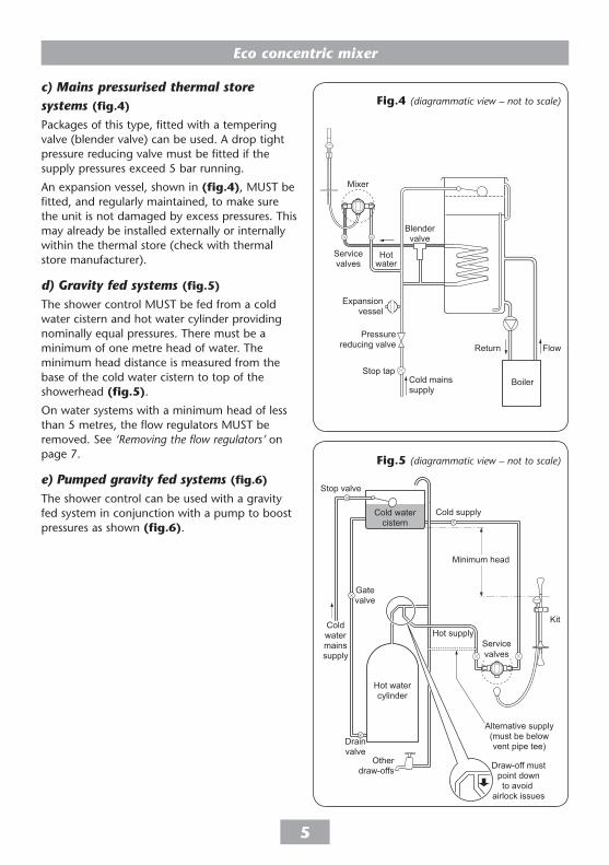
c) Mains pressurised thermal storesystems (fig.�)
Packages of this type, fitted with a tempering valve (blender valve) can be used. A drop tight pressure reducing valve must be fitted if the supply pressures exceed 5 bar running.
An expansion vessel, shown in (fig.�), MuST be fitted, and regularly maintained, to make sure the unit is not damaged by excess pressures. This may already be installed externally or internally within the thermal store (check with thermal store manufacturer).
d) gravity fed systems (fig.�)
The shower control MuST be fed from a cold water cistern and hot water cylinder providing nominally equal pressures. There must be a minimum of one metre head of water. The minimum head distance is measured from the base of the cold water cistern to top of the showerhead (fig.�).
On water systems with a minimum head of less than 5 metres, the flow regulators MuST be removed. See ‘Removing the flow regulators’ on page 7.
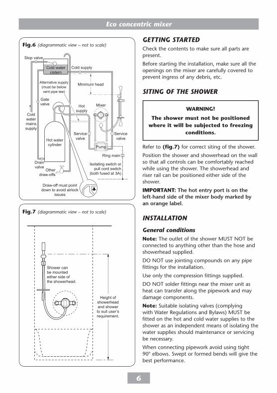
e) Pumped gravity fed systems (fig.6)
The shower control can be used with a gravity fed system in conjunction with a pump to boost pressures as shown (fig.6).
Blender valve
Flow
Cold mains supply
Hot water
Stop tap
Expansion vessel
Pressure reducing valve Return
Service valves
Mixer
Boiler
Fig.� (diagrammatic view – not to scale)
Hot watercylinder
Kit
Cold supply
Hot supply
Alternative supply(must be belowvent pipe tee)
Coldwatermainssupply
Drainvalve
Gatevalve
Stop valve
Cold watercistern
Minimum head
Otherdraw-offs Draw-off must
point downto avoid
airlock issues
Servicevalves
Fig.� (diagrammatic view – not to scale)
Eco concentric mixer
6
gEttIng startEDCheck the contents to make sure all parts are present.
Before starting the installation, make sure all the openings on the mixer are carefully covered to prevent ingress of any debris, etc.
sItIng of thE showEr
Refer to (fig.7) for correct siting of the shower.
Position the shower and showerhead on the wall so that all controls can be comfortably reached while using the shower. The showerhead and riser rail can be positioned either side of the shower.
Important: the hot entry port is on the left-hand side of the mixer body marked by an orange label.
InstallatIon
general conditionsnote: The outlet of the shower MuST nOT be connected to anything other than the hose and showerhead supplied.
DO nOT use jointing compounds on any pipe fittings for the installation.
use only the compression fittings supplied.
DO nOT solder fittings near the mixer unit as heat can transfer along the pipework and may damage components.
note: Suitable isolating valves (complying with Water Regulations and Bylaws) MuST be fitted on the hot and cold water supplies to the shower as an independent means of isolating the water supplies should maintenance or servicing be necessary.
When connecting pipework avoid using tight 90° elbows. Swept or formed bends will give the best performance.
the shower must not be positioned where it will be subjected to freezing
conditions.
Eco concentric mixer
7
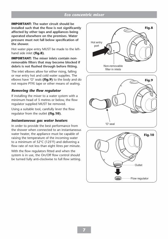
Important: the water circuit should be installed such that the flow is not significantly affected by other taps and appliances being operated elsewhere on the premises. Water pressure must not fall below specification of the shower.
Hot water pipe entry MuST be made to the left-hand side inlet (fig.8).
Important: the mixer inlets contain non-removable filters that may become blocked if debris is not flushed through before fitting.
The inlet elbows allow for either rising, falling or rear entry hot and cold water supplies. The elbows have ‘O’ seals (fig.9) to the body and do not require PTFE tape or other means of sealing.
removing the flow regulatorIf installing the mixer to a water system with a minimum head of 5 metres or below, the flow regulator supplied MuST be removed.
using a suitable tool, carefully lever the flow regulator from the outlet (fig.�0).
Instantaneous gas water heatersIn order to provide the best performance from the shower when connected to an instantaneous water heater, the appliance must be capable of raising the temperature of the incoming water to a minimum of 52°C (125°F) and delivering a flow rate of not less than eight litres per minute.
With the flow regulators fitted and when the system is in use, the On/Off flow control should be turned fully anti-clockwise to full flow setting.
Hot entryport
Non-removablefilter in inlets
Fig.8
'O' seal
Fig.9
Flow regulator
Outlet
Fig.�0
Eco concentric mixer
8
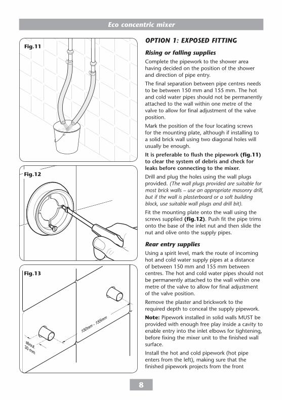
oPtIon 1: ExPosED fIttIng
rising or falling suppliesComplete the pipework to the shower area having decided on the position of the shower and direction of pipe entry.
The final separation between pipe centres needs to be between 150 mm and 155 mm. The hot and cold water pipes should not be permanently attached to the wall within one metre of the valve to allow for final adjustment of the valve position.
Mark the position of the four locating screws for the mounting plate, although if installing to a solid brick wall using two diagonal holes will usually be enough.
It is preferable to flush the pipework (fig.��) to clear the system of debris and check for leaks before connecting to the mixer.
Drill and plug the holes using the wall plugs provided. (The wall plugs provided are suitable for most brick walls – use an appropriate masonry drill, but if the wall is plasterboard or a soft building block, use suitable wall plugs and drill bit).
Fit the mounting plate onto the wall using the screws supplied (fig.��). Push fit the pipe trims onto the base of the inlet nut and then slide the nut and olive onto the supply pipes.
rear entry suppliesusing a spirit level, mark the route of incoming hot and cold water supply pipes at a distance of between 150 mm and 155 mm between centres. The hot and cold water pipes should not be permanently attached to the wall within one metre of the valve to allow for final adjustment of the valve position.
Remove the plaster and brickwork to the required depth to conceal the supply pipework.
note: Pipework installed in solid walls MuST be provided with enough free play inside a cavity to enable entry into the inlet elbows for tightening, before fixing the mixer unit to the finished wall surface.
Install the hot and cold pipework (hot pipe enters from the left), making sure that the finished pipework projects from the front
Fig.��
about 30 mm
150mm - 155mm
Fig.��
Fig.��
Eco concentric mixer
9
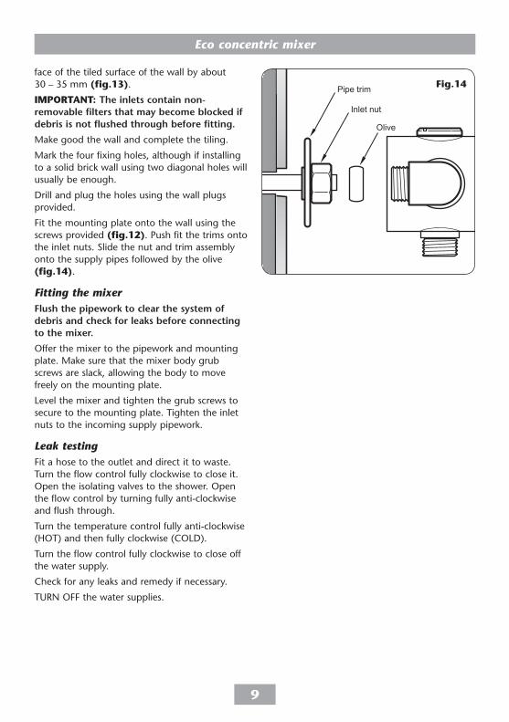
face of the tiled surface of the wall by about 30 – 35 mm (fig.��).
Important: the inlets contain non-removable filters that may become blocked if debris is not flushed through before fitting.
Make good the wall and complete the tiling.
Mark the four fixing holes, although if installing to a solid brick wall using two diagonal holes will usually be enough.
Drill and plug the holes using the wall plugs provided.
Fit the mounting plate onto the wall using the screws provided (fig.��). Push fit the trims onto the inlet nuts. Slide the nut and trim assembly onto the supply pipes followed by the olive (fig.��).
fitting the mixerFlush the pipework to clear the system of debris and check for leaks before connecting to the mixer.
Offer the mixer to the pipework and mounting plate. Make sure that the mixer body grub screws are slack, allowing the body to move freely on the mounting plate.
Level the mixer and tighten the grub screws to secure to the mounting plate. Tighten the inlet nuts to the incoming supply pipework.
leak testingFit a hose to the outlet and direct it to waste. Turn the flow control fully clockwise to close it. Open the isolating valves to the shower. Open the flow control by turning fully anti-clockwise and flush through.
Turn the temperature control fully anti-clockwise (HOT) and then fully clockwise (COLD).
Turn the flow control fully clockwise to close off the water supply.
Check for any leaks and remedy if necessary.
TuRn OFF the water supplies.
Inlet nut
Pipe trim
Olive
Fig.��
Eco concentric mixer
�0
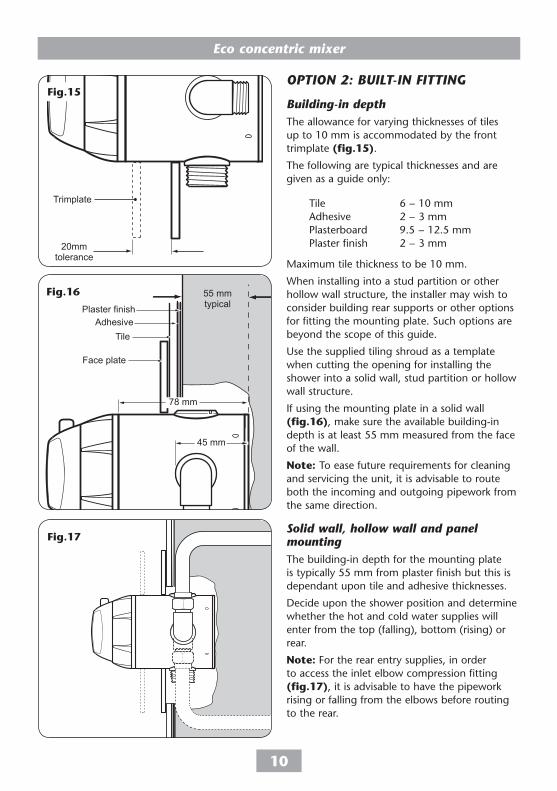
oPtIon 2: buIlt-In fIttIng
building-in depthThe allowance for varying thicknesses of tiles up to 10 mm is accommodated by the front trimplate (fig.��).
The following are typical thicknesses and are given as a guide only:
Tile 6 − 10 mm Adhesive 2 − 3 mm Plasterboard 9.5 − 12.5 mm Plaster finish 2 − 3 mm
Maximum tile thickness to be 10 mm.
When installing into a stud partition or other hollow wall structure, the installer may wish to consider building rear supports or other options for fitting the mounting plate. Such options are beyond the scope of this guide.
use the supplied tiling shroud as a template when cutting the opening for installing the shower into a solid wall, stud partition or hollow wall structure.
If using the mounting plate in a solid wall (fig.�6), make sure the available building-in depth is at least 55 mm measured from the face of the wall.
note: To ease future requirements for cleaning and servicing the unit, it is advisable to route both the incoming and outgoing pipework from the same direction.
solid wall, hollow wall and panel mountingThe building-in depth for the mounting plate is typically 55 mm from plaster finish but this is dependant upon tile and adhesive thicknesses.
Decide upon the shower position and determine whether the hot and cold water supplies will enter from the top (falling), bottom (rising) or rear.
note: For the rear entry supplies, in order to access the inlet elbow compression fitting (fig.�7), it is advisable to have the pipework rising or falling from the elbows before routing to the rear.
Plaster finish
TileAdhesive
Face plate
55 mmtypical
45 mm
78 mm
Fig.�7
20mmtolerance
Trimplate
Fig.��
Fig.�6
Eco concentric mixer
��
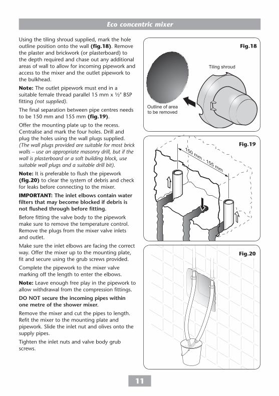
using the tiling shroud supplied, mark the hole outline position onto the wall (fig.�8). Remove the plaster and brickwork (or plasterboard) to the depth required and chase out any additional areas of wall to allow for incoming pipework and access to the mixer and the outlet pipework to the bulkhead.
note: The outlet pipework must end in a suitable female thread parallel 15 mm x ½" BSP fitting (not supplied).
The final separation between pipe centres needs to be 150 mm and 155 mm (fig.�9).
Offer the mounting plate up to the recess. Centralise and mark the four holes. Drill and plug the holes using the wall plugs supplied. (The wall plugs provided are suitable for most brick walls – use an appropriate masonry drill, but if the wall is plasterboard or a soft building block, use suitable wall plugs and a suitable drill bit).
note: It is preferable to flush the pipework (fig.�0) to clear the system of debris and check for leaks before connecting to the mixer.
Important: the inlet elbows contain water filters that may become blocked if debris is not flushed through before fitting.
Before fitting the valve body to the pipework make sure to remove the temperature control. Remove the plugs from the mixer valve inlets and outlet.
Make sure the inlet elbows are facing the correct way. Offer the mixer up to the mounting plate, fit and secure using the grub screws provided.
Complete the pipework to the mixer valve marking off the length to enter the elbows.
note: Leave enough free play in the pipework to allow withdrawal from the compression fittings.
Do not secure the incoming pipes within one metre of the shower mixer.
Remove the mixer and cut the pipes to length. Refit the mixer to the mounting plate and pipework. Slide the inlet nut and olives onto the supply pipes.
Tighten the inlet nuts and valve body grub screws.
150 mm - 155 mm
Fig.�9
Fig.�0
Outline of areato be removed
Tiling shroud
Fig.�8
Eco concentric mixer
��
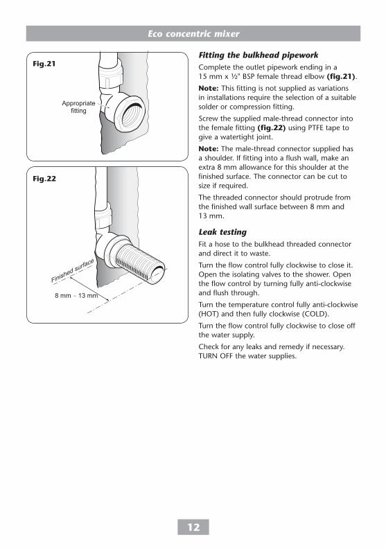
fitting the bulkhead pipeworkComplete the outlet pipework ending in a 15 mm x ½" BSP female thread elbow (fig.��).
note: This fitting is not supplied as variations in installations require the selection of a suitable solder or compression fitting.
Screw the supplied male-thread connector into the female fitting (fig.��) using PTFE tape to give a watertight joint.
note: The male-thread connector supplied has a shoulder. If fitting into a flush wall, make an extra 8 mm allowance for this shoulder at the finished surface. The connector can be cut to size if required.
The threaded connector should protrude from the finished wall surface between 8 mm and 13 mm.
leak testingFit a hose to the bulkhead threaded connector and direct it to waste.
Turn the flow control fully clockwise to close it. Open the isolating valves to the shower. Open the flow control by turning fully anti-clockwise and flush through.
Turn the temperature control fully anti-clockwise (HOT) and then fully clockwise (COLD).
Turn the flow control fully clockwise to close off the water supply.
Check for any leaks and remedy if necessary. TuRn OFF the water supplies.
Appropriatefitting
8 mm − 13 mm
Finished surface
Fig.��
Fig.��
Eco concentric mixer
��
Making goodPlace the tiling shroud over the shower mixer and secure temporarily. Make good the incoming and outlet pipe channelling and around the bulkhead outlet. Plaster or tile up to the edge of the shroud.
note: The tiles must be accurately cut to match the profile of the shroud. The outer cover will then accurately seal the hole, and enable the mixer unit to be removed from the mounting bracket without the need to break any tiles.
Make sure the grout lines are flush with the tiles in order to provide a smooth sealing surface for the outer cover. When complete, remove the tiling shroud.
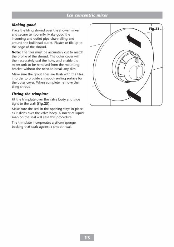
fitting the trimplateFit the trimplate over the valve body and slide tight to the wall (fig.��).
Make sure the seal in the opening stays in place as it slides over the valve body. A smear of liquid soap on the seal will ease this procedure.
The trimplate incorporates a silicon sponge backing that seals against a smooth wall.
Fig.��
Eco concentric mixer
��
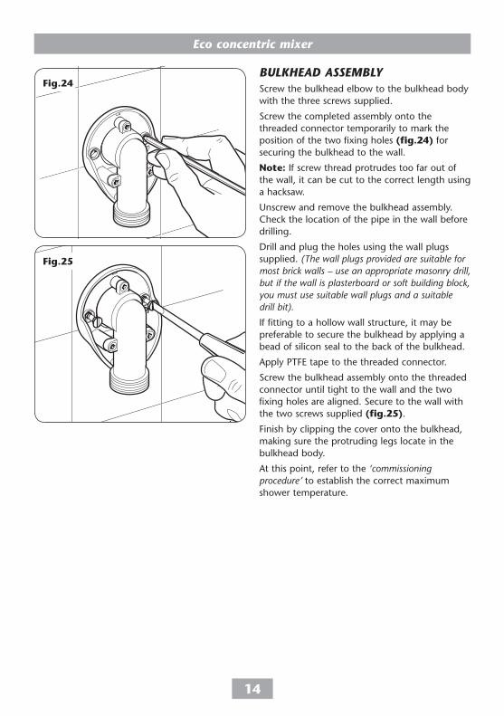
bulkhEaD assEMblyScrew the bulkhead elbow to the bulkhead body with the three screws supplied.
Screw the completed assembly onto the threaded connector temporarily to mark the position of the two fixing holes (fig.��) for securing the bulkhead to the wall.
note: If screw thread protrudes too far out of the wall, it can be cut to the correct length using a hacksaw.
unscrew and remove the bulkhead assembly. Check the location of the pipe in the wall before drilling.
Drill and plug the holes using the wall plugs supplied. (The wall plugs provided are suitable for most brick walls – use an appropriate masonry drill, but if the wall is plasterboard or soft building block, you must use suitable wall plugs and a suitable drill bit).
If fitting to a hollow wall structure, it may be preferable to secure the bulkhead by applying a bead of silicon seal to the back of the bulkhead.
Apply PTFE tape to the threaded connector.
Screw the bulkhead assembly onto the threaded connector until tight to the wall and the two fixing holes are aligned. Secure to the wall with the two screws supplied (fig.��).
Finish by clipping the cover onto the bulkhead, making sure the protruding legs locate in the bulkhead body.
At this point, refer to the ‘commissioning procedure’ to establish the correct maximum shower temperature.
Fig.��
Fig.��
Eco concentric mixer
��
CoMMIssIonIngImportant: Make sure that all supply pipework has been flushed through before commissioning.
Make sure that both hot and cold water supplies are fully open and their design temperature and pressures and are within the requirements as stated.
Make sure the temperature control is at the maximum temperature setting, i.e. rotated fully anti-clockwise, and make sure the showerhead is directed to waste.
Start the water flow by turning the flow control anti-clockwise. Allow the shower to run at the maximum temperature setting until the water temperature has stabilised. Rotate the temperature control anti-clockwise until the desired maximum showering temperature is reached.
The mixer has a temperature stop to prevent accidental rotation to higher temperatures. This is adjustable to provide a maximum temperature of 35°C – 45°C.
Important
It is advisable to carry out a flow rate test to confirm compliance with the flow requirements.
to run a flow a rate test, direct the shower outlet into a bucket. turn the mixer on at full flow for 20 seconds and then turn off. to comply with the flow requirements the bucket should contain no more than 3 litres of water.
Eco concentric mixer
�6
Fig.�6
Fig.�7
Temperaturestop
Temperaturecontrol ring
Fig.�8
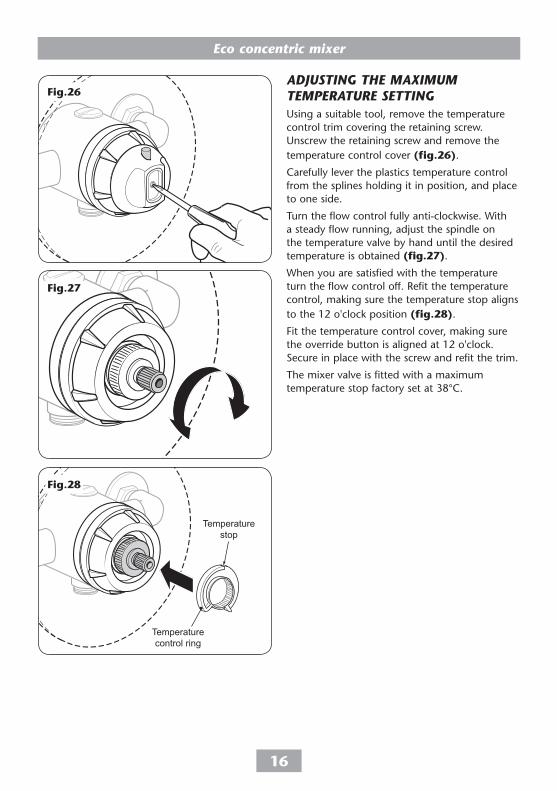
aDjustIng thE MaxIMuM tEMPEraturE sEttIngusing a suitable tool, remove the temperature control trim covering the retaining screw. unscrew the retaining screw and remove the temperature control cover (fig.�6).
Carefully lever the plastics temperature control from the splines holding it in position, and place to one side.
Turn the flow control fully anti-clockwise. With a steady flow running, adjust the spindle on the temperature valve by hand until the desired temperature is obtained (fig.�7).
When you are satisfied with the temperature turn the flow control off. Refit the temperature control, making sure the temperature stop aligns to the 12 o'clock position (fig.�8).
Fit the temperature control cover, making sure the override button is aligned at 12 o'clock. Secure in place with the screw and refit the trim.
The mixer valve is fitted with a maximum temperature stop factory set at 38°C.
Eco concentric mixer
�7
WarnInG!
Do not use ‘powerful’ abrasive or solvent cleaning fluids when cleaning the shower as they may damage the
plastic fittings.
OnOff
CoolerHotter
Press overridebutton
then rotate
Flow control
Temperature control
Temperature control
Fig.�9
OnOff
CoolerHotter
Press overridebutton
then rotate
Flow control
Temperature control
Temperature control
Fig.�0
OnOff
CoolerHotter
Press overridebutton
then rotate
Flow control
Temperature control
Temperature control
Fig.��
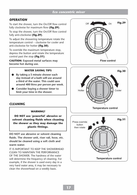
WatEr SavInG tIpS
By taking a 5 minute shower each day instead of a bath will use around a third of the water. this could save around 400 litres per person per week.
Consider buying a shower timer to limit your time in the shower.
oPEratIonTo start the shower, turn the On/Off flow control fully clockwise for maximum flow (fig.�9).
To stop the shower, turn the On/Off flow control fully anti-clockwise (fig.�9).
To adjust the showering temperature rotate the temperature control – clockwise for cooler and anti-clockwise for hotter (fig.�0).
To override the maximum temperature stop, depress the button and rotate the temperature control past the stop (fig.��).
cautIon: Exposed metal surfaces may become hot during use.
ClEanIng
Do not use abrasive or solvent cleaning fluids. the shower unit, riser rail, hose, etc. should be cleaned using a soft cloth and warm water.
IT IS IMPORTAnT TO KEEP THE SHOWERHEAD CLEAn TO MAInTAIn THE PERFORMAnCE OF THE SHOWER. The hardness of the water will determine the frequency of cleaning. For example, if the shower is used every day in a very hard water area, it may be necessary to clean the showerhead on a weekly basis.
Eco concentric mixer
�8
aDjustIng thE showErhEaDFive showerhead patterns are available (fig.��). Adjust the spray pattern by turning the bezel on the showerhead in either direction until the desired pattern is obtained.
Fig.��
Eco concentric mixer
�9
Sprayplatekey
Sprayplate
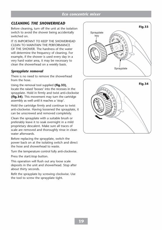
ClEanIng thE showErhEaDBefore cleaning, turn off the unit at the isolation switch to avoid the shower being accidentally switched on.
IT IS IMPORTAnT TO KEEP THE SHOWERHEAD CLEAn TO MAInTAIn THE PERFORMAnCE OF THE SHOWER. The hardness of the water will determine the frequency of cleaning. For example, if the shower is used every day in a very hard water area, it may be necessary to clean the showerhead on a weekly basis.
sprayplate removalThere is no need to remove the showerhead from the hose.
using the removal tool supplied (fig.��), locate the raised ’bosses’ into the recesses in the sprayplate. Hold in firmly and twist anti-clockwise (fig.��). This movement may turn the cartridge assembly as well until it reaches a ‘stop’.
Hold the cartridge firmly and continue to twist anti-clockwise. Having loosened the sprayplate, it can be unscrewed and removed completely.
Clean the sprayplate with a suitable brush or preferably leave it to soak overnight in a mild proprietary descalent. Make sure all traces of scale are removed and thoroughly rinse in clean water afterwards.
Before replacing the sprayplate, switch the power back on at the isolating switch and direct the hose and showerhead to waste.
Turn the temperature control fully anti-clockwise.
Press the start/stop button.
This operation will flush out any loose scale deposits in the unit and showerhead. Stop after about thirty seconds.
Refit the sprayplate by screwing clockwise. use the tool to screw the sprayplate tight.
– Check valve assembly including check valve & filter
83310130
– Bulkhead fitting 85500230
– nutted long thread connector 7032915
34
5 6
78
9
10
10
�
2
Eco concentric mixer
��
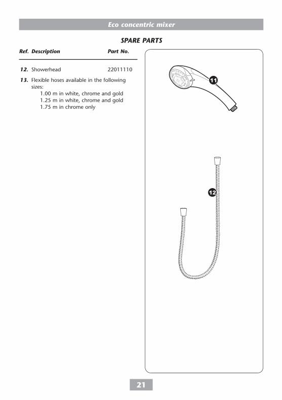
sParE Parts
ref. Description Part no.
12. Showerhead 22011110
13. Flexible hoses available in the following sizes: 1.00 m in white, chrome and gold 1.25 m in white, chrome and gold 1.75 m in chrome only
11
12
Eco concentric mixer
��
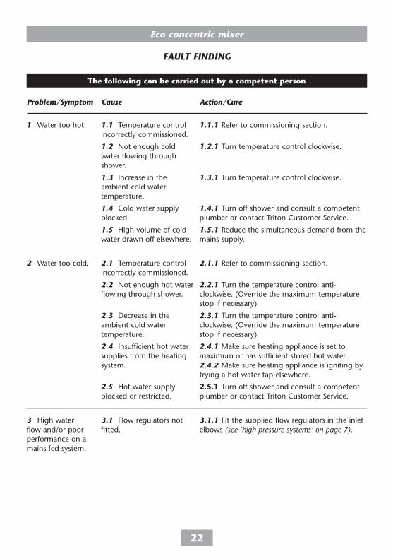
fault fInDIng
Problem/symptom Cause action/Cure
1 Water too hot.
2 Water too cold.
3 High water flow and/or poor performance on a mains fed system.
1.1 Temperature control incorrectly commissioned.
1.2 not enough cold water flowing through shower.
1.3 Increase in the ambient cold water temperature.
1.4 Cold water supply blocked.
1.5 High volume of cold water drawn off elsewhere.
2.1 Temperature control incorrectly commissioned.
2.2 not enough hot water flowing through shower.
2.3 Decrease in the ambient cold water temperature.
2.4 Insufficient hot water supplies from the heating system.
2.5 Hot water supply blocked or restricted.
3.1 Flow regulators not fitted.
1.1.1 Refer to commissioning section.
1.2.1 Turn temperature control clockwise.
1.3.1 Turn temperature control clockwise.
1.4.1 Turn off shower and consult a competent plumber or contact Triton Customer Service.
1.5.1 Reduce the simultaneous demand from the mains supply.
2.1.1 Refer to commissioning section.
2.2.1 Turn the temperature control anti-clockwise. (Override the maximum temperature stop if necessary).
2.3.1 Turn the temperature control anti-clockwise. (Override the maximum temperature stop if necessary).
2.4.1 Make sure heating appliance is set to maximum or has sufficient stored hot water. 2.4.2 Make sure heating appliance is igniting by trying a hot water tap elsewhere.
�.�.� Turn off shower and consult a competent plumber or contact Triton Customer Service.
3.1.1 Fit the supplied flow regulators in the inlet elbows (see ‘high pressure systems’ on page 7).
the following can be carried out by a competent person
Eco concentric mixer
��
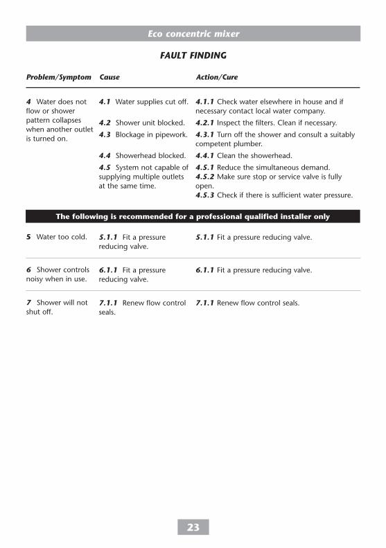
fault fInDIng
Problem/symptom Cause action/Cure
4.1 Water supplies cut off.
4.2 Shower unit blocked.
4.3 Blockage in pipework.
4.4 Showerhead blocked.
4.5 System not capable of supplying multiple outlets at the same time.
5.1.1 Fit a pressure reducing valve.
6.1.1 Fit a pressure reducing valve.
7.1.1 Renew flow control seals.
4.1.1 Check water elsewhere in house and if necessary contact local water company.
4.2.1 Inspect the filters. Clean if necessary.
4.3.1 Turn off the shower and consult a suitably competent plumber.
4.4.1 Clean the showerhead.
4.5.1 Reduce the simultaneous demand. 4.5.2 Make sure stop or service valve is fully open. 4.5.3 Check if there is sufficient water pressure.
5.1.1 Fit a pressure reducing valve.
6.1.1 Fit a pressure reducing valve.
7.1.1 Renew flow control seals.
4 Water does not flow or shower pattern collapses when another outlet is turned on.
� Water too cold.
6 Shower controls noisy when in use.
7 Shower will not shut off.
the following is recommended for a professional qualified installer only
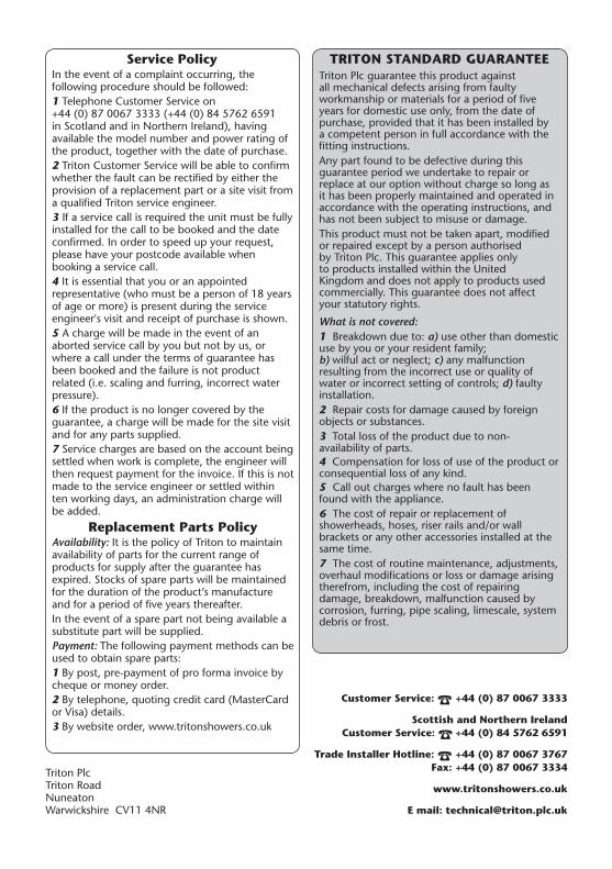
trIton StanDarD GuarantEETriton Plc guarantee this product against all mechanical defects arising from faulty workmanship or materials for a period of five years for domestic use only, from the date of purchase, provided that it has been installed by a competent person in full accordance with the fitting instructions.Any part found to be defective during this guarantee period we undertake to repair or replace at our option without charge so long as it has been properly maintained and operated in accordance with the operating instructions, and has not been subject to misuse or damage.This product must not be taken apart, modified or repaired except by a person authorised by Triton Plc. This guarantee applies only to products installed within the united Kingdom and does not apply to products used commercially. This guarantee does not affect your statutory rights.
What is not covered:1 Breakdown due to: a) use other than domestic use by you or your resident family; b) wilful act or neglect; c) any malfunction resulting from the incorrect use or quality of water or incorrect setting of controls; d) faulty installation.2 Repair costs for damage caused by foreign objects or substances.3 Total loss of the product due to non-availability of parts.4 Compensation for loss of use of the product or consequential loss of any kind.5 Call out charges where no fault has been found with the appliance.6 The cost of repair or replacement of showerheads, hoses, riser rails and/or wall brackets or any other accessories installed at the same time.7 The cost of routine maintenance, adjustments, overhaul modifications or loss or damage arising therefrom, including the cost of repairing damage, breakdown, malfunction caused by corrosion, furring, pipe scaling, limescale, system debris or frost.
Service policyIn the event of a complaint occurring, the following procedure should be followed:1 Telephone Customer Service on +44 (0) 87 0067 3333 (+44 (0) 84 5762 6591 in Scotland and in northern Ireland), having available the model number and power rating of the product, together with the date of purchase.2 Triton Customer Service will be able to confirm whether the fault can be rectified by either the provision of a replacement part or a site visit from a qualified Triton service engineer.3 If a service call is required the unit must be fully installed for the call to be booked and the date confirmed. In order to speed up your request, please have your postcode available when booking a service call.4 It is essential that you or an appointed representative (who must be a person of 18 years of age or more) is present during the service engineer's visit and receipt of purchase is shown.5 A charge will be made in the event of an aborted service call by you but not by us, or where a call under the terms of guarantee has been booked and the failure is not product related (i.e. scaling and furring, incorrect water pressure). 6 If the product is no longer covered by the guarantee, a charge will be made for the site visit and for any parts supplied.7 Service charges are based on the account being settled when work is complete, the engineer will then request payment for the invoice. If this is not made to the service engineer or settled within ten working days, an administration charge will be added.
replacement parts policyAvailability: It is the policy of Triton to maintain availability of parts for the current range of products for supply after the guarantee has expired. Stocks of spare parts will be maintained for the duration of the product’s manufacture and for a period of five years thereafter.In the event of a spare part not being available a substitute part will be supplied.Payment: The following payment methods can be used to obtain spare parts:1 By post, pre-payment of pro forma invoice by cheque or money order.2 By telephone, quoting credit card (MasterCard or Visa) details.3 By website order, www.tritonshowers.co.uk