1 Data Acquisitions, Trigger, Controls Martin L. Purschke, Brookhaven National Laboratory ( … but never dared to ask. ) What you always wanted to know about... Data Acquisitions, Trigger, Controls
Transcript
1
Data Acquisitions, Trigger, Controls
Martin L. Purschke, Brookhaven National Laboratory
( … but never dared to ask. )
What you always wanted to know about...
Data Acquisitions, Trigger, Controls
2
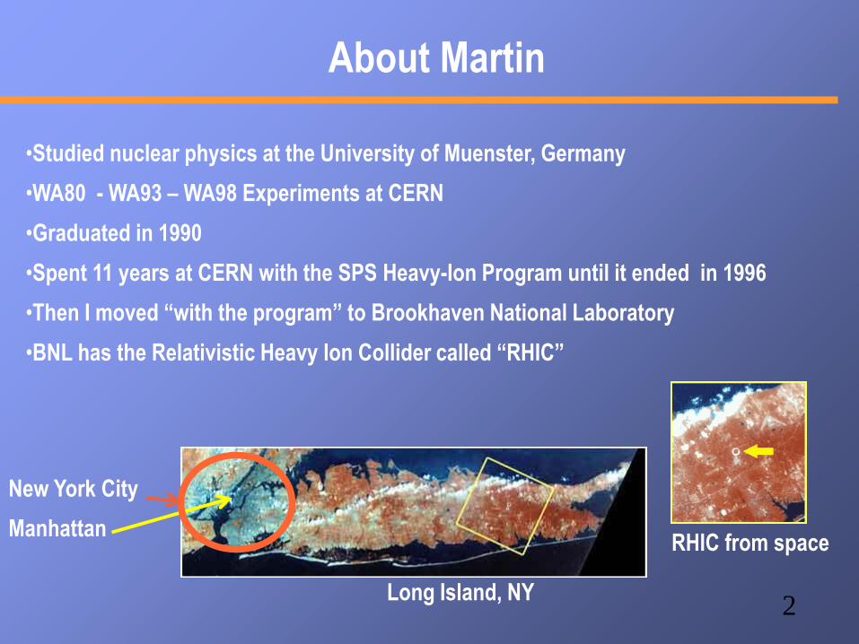
About Martin
•Studied nuclear physics at the University of Muenster, Germany
•WA80 - WA93 – WA98 Experiments at CERN
•Graduated in 1990
•Spent 11 years at CERN with the SPS Heavy-Ion Program until it ended in 1996
•Then I moved “with the program” to Brookhaven National Laboratory
•BNL has the Relativistic Heavy Ion Collider called “RHIC”
Long Island, NY
New York City
ManhattanRHIC from space
RHIC/PHENIX at a glance
RHIC:
2 independent rings, one beam clockwise,
the other counterclockwise
sqrt(SNN)= 500GeV * Z/A
~200 GeV for Heavy Ions
~500 GeV for proton-proton (polarized)
PHENIX:
4 spectrometer arms
12 Detector subsystems
2500,000 detector channels
Lots of readout electronics
Data rate ~7KHz (AuAu) , 9KHz
(pp)
Data Logging rate ~900-1200 MB/s
1600MB/s max
Medical Imaging / PET @BNL
Original Ratcap V1
Plant Scanner
Breast Scanner
UPenn Scanner 400MB/s DAQ application
5
PHENIX - an “early” high-rate experiment
My opening slide at the
Computing for High-Energy
Physics Conference in
Mumbai, India, 2006
I am the Data Acquisition Coordinator for PHENIX and our
successor experiment “sPHENIX”
… and that's why I'm here today.
6
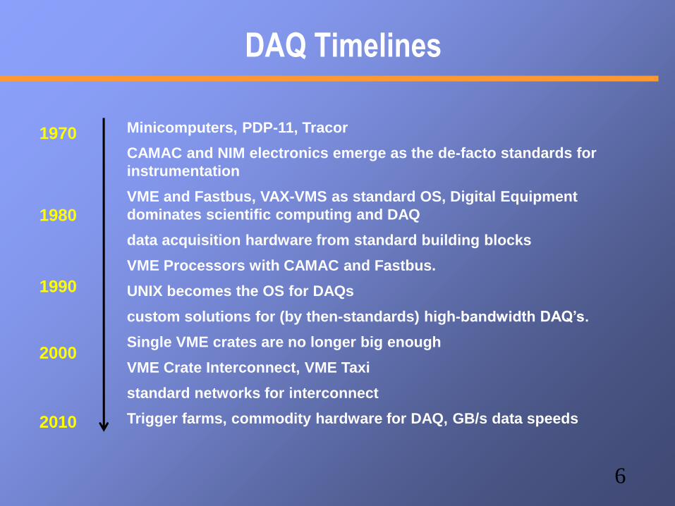
DAQ Timelines
Minicomputers, PDP-11, Tracor
CAMAC and NIM electronics emerge as the de-facto standards for
instrumentation
VME and Fastbus, VAX-VMS as standard OS, Digital Equipment
dominates scientific computing and DAQ
data acquisition hardware from standard building blocks
VME Processors with CAMAC and Fastbus.
UNIX becomes the OS for DAQs
custom solutions for (by then-standards) high-bandwidth DAQ’s.
Single VME crates are no longer big enough
VME Crate Interconnect, VME Taxi
standard networks for interconnect
Trigger farms, commodity hardware for DAQ, GB/s data speeds
1970
1980
1990
2000
2010
7
There is a name...
Even today, many modern detector elements and prototypes see
their first test using LeCroy electronics
“I did it in Blue Logic”, referring to the LC blue color
Also, a prestigious series of “Electronics for Future Colliders”
conferences held at LeCroy’s headquarters in the early 90’s
There are many manufacturers (CAEN, …), but this era of
physics instrumentation is really associated with…
… Walter LeCroy
8
Computing ca. 1985
Our flagship mainframe computer, a
Digital Equipment VAX 780
About 1/8 as much computing power
as my Nexus 5 smartphone these
days
Not as much memory though... 4MB
But a great OS, OpenVMS
And this is a DEC
VT100 terminal,
where most of the
work took place in
those days.
This is a RA81 harddisk. 600MB,
just enough to hold the contents of
one data tape
9
3 Fundamental Signal Standards
TTL – Transistor-Transistor Logic
0-5V digital signal range
Popular in circuit boards because of a wide range of
IC (74LSxxxx)
Poor timing characteristics, high currents (= power)
needed – largely obsolete
NIM – Nuclear Instrumentation Module ( AEC
Standard)
Defines a crate standard, connectors, and
power/voltage supply levels, as well as a signal
standard
The signals are defined as currents (-16mA into 50
Ohm – makes about -800mV). Negative signals
Virtually every experiment has them. This what made
standardization in instrumentation possible
Modules can be inserted and removed “hot”
10
Signal Standards - ECL
ECL – Emitter Coupled Logic
Part of the NIM standard
Excellent timing characteristics – constant current gets
routed on way or another, no capacitance charging
High-Density (well, back some years) connectors with
twisted-pair or short flat cables
A “bus” of ECL lines can connect to multiple inputs, last
one gets terminated – convenient at times
Flat cables make it harder to make wiring mistakes
But mostly chosen for speed and density.
Constant current makes for high power consumption
though
11
Why do we need to know the “classic” things?
Even in 2014, you are likely to use CAMAC / VME for the initial tests of the detector
Results obtained with “known” electronics drive the development of your final readout
That final readout is likely not available by the time you go to test beams
FermiLab test beam Sep. 2013
For the PHENIX-MPCEX detector
Struck SIS3300 Flash ADCs (VME)
(Also a DRS4 eval. Board...)
12
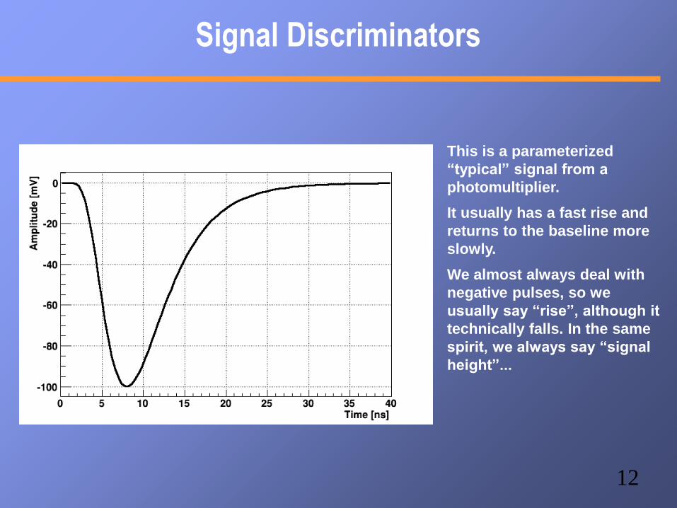
Signal Discriminators
This is a parameterized
“typical” signal from a
photomultiplier.
It usually has a fast rise and
returns to the baseline more
slowly.
We almost always deal with
negative pulses, so we
usually say “rise”, although it
technically falls. In the same
spirit, we always say “signal
height”...
13
Signal Discriminators
Of course the signal heights
vary from pulse to pulse
There is also noise – a myriad
of tiny pulses which have
nothing to do with a signal in
your detector
You want to know whether or
not a signal is higher than a
certain threshold – this could
translate into a minimum
required energy deposited,
for example
All signals on the left have the
same form, just a different
amplitude
14
Signal Discriminators
In this example, we set a
threshold of -40mV.
The black, green, and blue
signals would make the cut
here.
We would ignore the magenta
and light blue signals here.Threshold
15
Signal Discriminators
This is what you might see on
your scope.
Where the signal exceeds the
threshold, you get the
discriminator to fire.Threshold
Most discriminators give a
logic pulse with a fixed
length, independent of the
“above-threshold-time” of the
signal. Has many advantages.Fixed-length logical signal
16
Signal Discriminators
This is what you might see on
your scope.
Where the signal exceeds the
threshold, you get the
discriminator to fire.
Most discriminators give a
logic pulse with a fixed
length, independent of the
“above-threshold-time” of
the signal. Has many
advantages.
Fixed-length logical signal
17
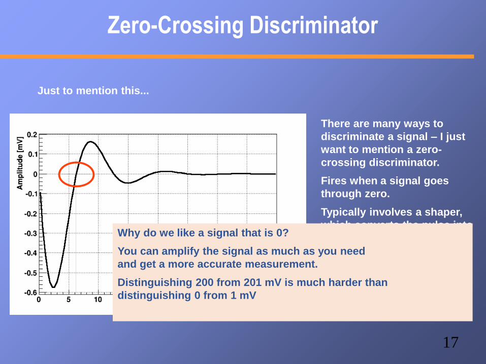
Zero-Crossing Discriminator
There are many ways to
discriminate a signal – I just
want to mention a zero-
crossing discriminator.
Fires when a signal goes
through zero.
Typically involves a shaper,
which converts the pulse into
a bipolar signal.
Just to mention this...
Why do we like a signal that is 0?
You can amplify the signal as much as you need
and get a more accurate measurement.
Distinguishing 200 from 201 mV is much harder than
distinguishing 0 from 1 mV
18
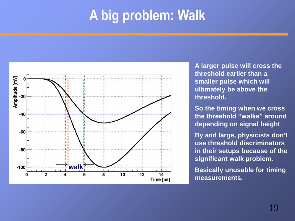
A big problem: Walk
A larger pulse will cross the
threshold earlier than a
smaller pulse which will
ultimately be above the
threshold.
So the timing when we cross
the threshold “walks” around
depending on signal height
By and large, physicists don't
use threshold discriminators
in their setups because of the
significant walk problem.
Basically unusable for timing
measurements.
19
A big problem: Walk
A larger pulse will cross the
threshold earlier than a
smaller pulse which will
ultimately be above the
threshold.
So the timing when we cross
the threshold “walks” around
depending on signal height
By and large, physicists don't
use threshold discriminators
in their setups because of the
significant walk problem.
Basically unusable for timing
measurements.
walk
20
Constant Fraction Discriminators
Well, a Constant Fraction Discriminator sounds like the golden solution
instead of a fixed threshold, you “adjust” the threshold pulse by pulse so
it fires at, say, 40% of the peak amplitude
No matter what the peak is, if the pulse shape is always the same, a
signal reaches its 40% level at the same time. Walk eliminated.
Problem solved... well, not so fast.
How do you know the peak amplitude? How do you do that?
Luckily, someone figured that one out...
21
The Constant Fraction Discriminator (CFD)
You take the signal, and subtract a delayed and attenuated copy from it
(or: you add an inverted, delayed and attenuated copy to it)
Inverted, attenuated, delayed copy
Original pulse
Inverted, attenuated, delayed copy
Original pulse
Resulting pulse
And then you use a zero-
crossing discriminator to find
the spot
22
Look, no walk!
This shows the zero-crossing
time of 3 different pulses
They all go through 0 at
exactly the same time
If the signals are amplified
copies (all the same shape),
this is mathematically exact
Of course, we are dealing
with real-life signals...
23
Data from our Time-of-Flight Setup
This are data taken by us here at the school with the TOF setup.
I picked a 0.6 fraction, 50 samples delay
That can still be improved...
Original Waveform
Delayed and inverted
Sum of the two
24
Slewing Correction
Real-life signals do usually not completely fulfill the “scaling
rule”
They do not have the exact same shape (still good enough for
many applications)
Example: Scintillator light does not simply “scale” -
depending on energy the light profile varies, and so does the
final pulse shape
For picosecond-level timing, one still needs to eliminate a
residual timing dependence on the pulse height
Measure the pulse height and perform a amplitude-dependent
correction -
“Slewing correction” - part of your offline analysis
25
A Cosmic Ray Test Stand
Actual Detector(s)you want to test
Cosmic rays
26
Let's Build a Cosmic Ray Teststand
Scintillator Paddle with PMT
Cosmics
ActualDetectoryou want
to test
CFD
CFD
Timing-defining
CFD (short width)
Coincidence unit
Trigger for DAQ
Signal(s) for
DAQ
DAQ
27
More BLTs...
The trigger of WA80 @ CERN
28
How to measure signals?
Two main devices:
An ADC – Analog to Digital Converter - converts a pulse
height or integrated charge in to a number
A TDC – Time to Digital Converter - converts the time
difference between a start and a stop signal into a number
You'll hear “10 bit” or “12 bit resolution” - how many bits
that number has. This is one contributor to the real resolution
– with 10bit you can get at most 0.1% (1/1024). Typically your
detector's resolution is much worse than that.
ADC – “charge integrating” or “Peak Sensing” … PS is rare,
charge-integrating is the most common ADC
signal
Gate
Integraton timeEven without an actual signal, an ADC
does not measure 0 - noise, dark
currents, etc make a “pedestal”. Needs to
be measured and subtracted
Charge integrating ADC are often the
most precise ADCs (you can lose signal
height, but you can't lose charge)
29
Flash ADCs
Rather than measuring one number, a Flash ADC samples the
signal at a specific frequency (10, 100 MHz, 1, 2, 5 GHz)
FADC gives you a waveform just like a scope
You can measure pedestals signal-by-signal (select samples
before the actual pulse)
Perform Waveform analysis
Much higher data volume though
FADCs are expensive
Switched-capacitor arrays can be a
cheaper alternative
we will use here the
DRS4 chip
30
More Standards
Now what? Can I buy one of those ADC's and read it out?
Depends. There are a few standards for such instrumentation so you can buy stuff off
the shelf.
CAMAC
VME
FASTBUS
Custom-made (most of PHENIX)
uTCA (I'll get back to this later)
31
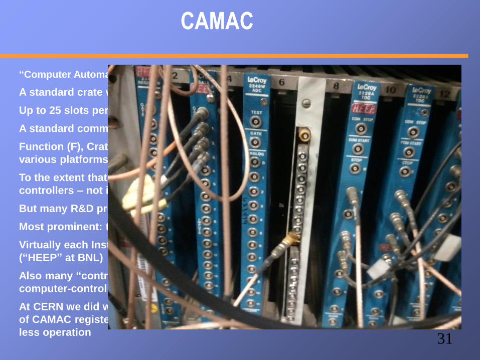
CAMAC
“Computer Automated Measurement and Control”
A standard crate with a bus-backplane
Up to 25 slots per crate, 2 typically taken by “Crate Controller”, 23 free
A standard communications interface, short-hand FCNA
Function (F), Crate (C), Station (N) (slot), Subaddress (A), with standard libraries on
various platforms
To the extent that we are using CAMAC, it is typically through our VME crate
controllers – not in the “real” PHENIX DAQ
But many R&D projects come to life initially using CAMAC modules
Most prominent: the LeCroy 2249W ADC and the LeCroy 2228A TDC
Virtually each Institute has a large inventory of CAMAC hardware, easy to get
(“HEEP” at BNL)
Also many “control” modules, such as the delay module before, in CAMAC for all
computer-controlled settings
At CERN we did what we do here by loading a LVL1 configuration by setting hundreds
of CAMAC registers – CFDs in CAMAC, Logic modules (“8LM”), delays,... screwdriver-
less operation
32
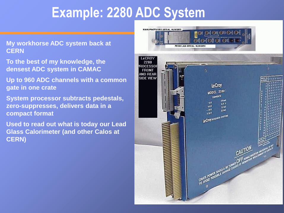
Example: 2280 ADC System
My workhorse ADC system back at
CERN
To the best of my knowledge, the
densest ADC system in CAMAC
Up to 960 ADC channels with a common
gate in one crate
System processor subtracts pedestals,
zero-suppresses, delivers data in a
compact format
Used to read out what is today our Lead
Glass Calorimeter (and other Calos at
CERN)
33
FASTBUS
Attempt to overcome some of CAMAC's limitations
Larger crate, more space, hot-swappable modules...
I have not used FB that much, so I'm not the expert
The reason that I skipped FB, however, is the “wrong sex” of the backplane
The backplane is by far the most expensive item in a crate
In FB the backplane has the pins. What??? You bend or break one while inserting a
module, and the backplane is shot
That said, JH's 787 experiment was all in FastBus... so it cannot be that bad
34
VME
“Virtual Memory Extender”, designed as a digital / computing device
Bus allows to memory-map modules and access them
Different modules can access each other's memory across the backplane
Many attempts to use VME for analog-type instrumentation (denser, faster,
cheaper than CAMAC)
However, standard VME crates don't have the proper clean power for
analog electronics
CERN's add-on standard “VIPA” guarantees certain limits, but makes VME
crates really expensive
Still, a wealth of modules in VME
All of PHENIX's DCMs, DCM2s, Partitioners are in VME (e.g VME crate
controllers, such as iocondev1a). All use of VME in the PHENIX DAQ is
digital-only
I like(ed) VME a lot for its ease of use
Easy to understand
Struck
SIS3300 8-
channel Flash
ADC
35
New(er) Developments
PET Scanner for
Mammography /
Rodents (3072 LYSO
crystals)
RCDAQ
“TSPM”
Prototype
DRS4 Eval board
“USB Oscilloscope”
Nice for triggering,
say, for cosmics
The SRS System
For various groups (medical imaging, GEM R&D, Stony Brook GEM Cherenkov, Yale...) I'm
providing a modern DAQ system running on a PC.
The principal data streams into a PC are network, USB, and PCI/PCIe
Most folks planning some test beam will likely interact with it. SB@SLAC (now), MPC-EX...
36
Dead Time
MoreThan10%!
Scientistsfor less
DeadtimeScientistsfor less
Deadtime
Lessthan10%!Less
than10%!
37
Dead Time
It takes some time to actually read out your detectors. You have
to transfer the data, package it, store it
Many “small” data acquisitions run in the neighborhood of 1
millisecond – so you can get an event rate of about 1KHz max.
During the time the DAQ is reading out, it cannot accept
another signal - “dead ”.
An event / signal arriving during that time is lost.
We measure dead time (or live time) in percent – 10%, 20%, …
If your dead time is 50%, a given signal has a 50% chance to
be accepted.
If your dead time is 10%, the chance is 90%.
38
Dead Time
If you have truly rare interesting events which you want to
measure in your overall data stream, you cannot afford such a
high dead time.
Example: PHENIX takes data at about 7KHz. We get about 300
J/Psi particles /day among all the millions of other events.
If we would be running at 50% dead, we would lose 150 out of
the 300.
We are running about 88% live, so we are losing 36 of the 300.
Of course we would like to run 99% live.
But then we would not take not a lot of data, and the J/Psi is
not the only thing we measure
→ Always a compromise.
39
An example from my past
WA98 @ CERN
Heavy-Ion Experiment at the SPS
Zero-Degree Calorimeter (measures Energy going forward). No or “grazing” collision
Mid-Rapidity calorimeter. No collision More violent collision – more energy
40
Centrality Trigger
High Centrality → small impact parameterLow Centrality → large impact parameter
41
Centrality Regions
High
Medium Centrality
Low
42
What is the problem?
1
105
108
For each high-centrality collision, you get
Such a central collision issomewhat rare
If you can take 1000 event/s –and your DAQ is 10% live –
You capture one of those eventsevery 4 hours and 40 minutes
You will never complete your measurement!
You need to do something different...
43
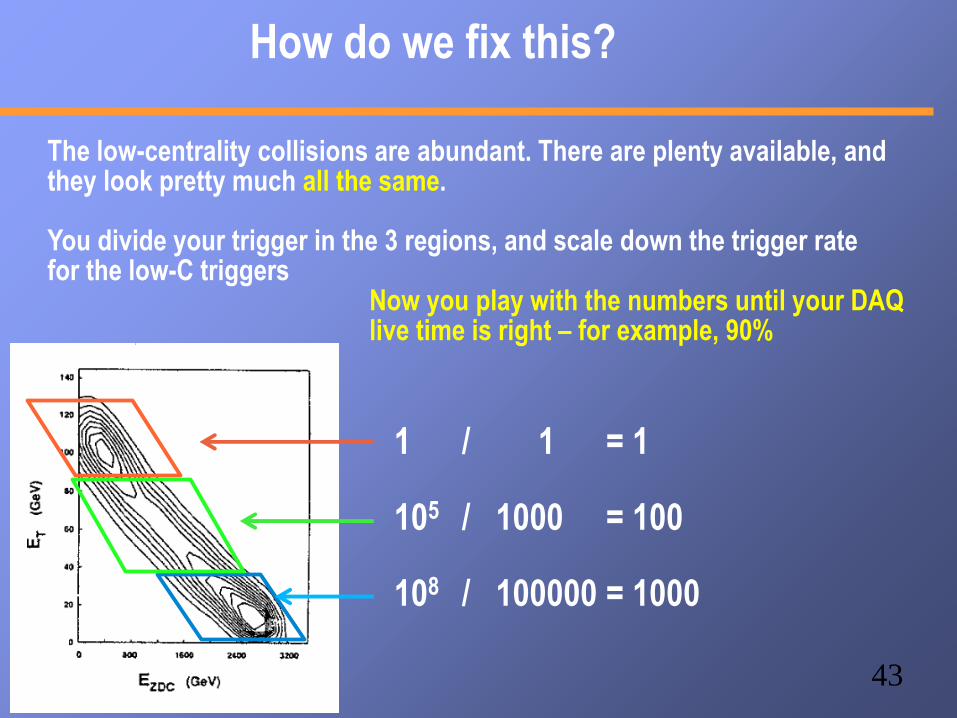
How do we fix this?
1 / 1 = 1
105 / 1000 = 100
108 / 100000 = 1000
The low-centrality collisions are abundant. There are plenty available, and they look pretty much all the same.
You divide your trigger in the 3 regions, and scale down the trigger ratefor the low-C triggers
Now you play with the numbers until your DAQlive time is right – for example, 90%
44
Pitfalls of the Scaledown
You offer your DAQ fewer events of the “abundant” types by
“scaling them down”
You offer the DAQ only each 5th, 100th, or 1000th event
VERY IMPORTANT: You can only count the events which
arrived during the live time of your DAQ.
The Event could have been taken (we just decided not to).
Then (and ONLY then) such an event represents 5, 100, or 1000
others of the same kind (that's pretty much how a poll for
politics works – you poll 5000 representative people)
When you analyze the data, you assign a weight of 5, 100, or
1000 (in this example) to it to account for the scaledown
45
End of Part 1.... I hope we made it here....
46
Let's go back here for a second
Scintillator Paddle with PMT
Cosmics
ActualDetectoryou want
to test
CFD
CFD
Coincidence unit
It takes time to form a trigger decision. Each
gate adds in the order of 20ns.
There is a very good chance that your trigger
decision is marginal at best
You need to gain some time for making the
trigger.
47
Too Late!
This is a screenshot where we see that
our gate would be too late for a “classic”
ADC
48
So what can you do?
Scintillator Paddle with PMT
Cosmics
ActualDetectoryou want
to test
CFD
CFD
Coincidence unit
In the 80's, we sent all signals through a long
cables (WA98 – 108 m) so the signals would
arrive only after the trigger decision has been
made
Expensive and ultimately limited – 600Km cables
To remember: RG58 and RG174 cables have
a speed of 5ns/m
108m → 540 ns trigger signals 30m,
subtract 150ns
49
Electronic delays instead
Here's what we concluded.
Move all analog electronics (ADCs, TDCs, etc) to the detector.
Those front-end modules (FEM) have some analog storage which allows to keep the
data from a certain number of crossings (e.g.% 64)
When the trigger decision finally arrives, we go back a number of storage cells,
digitize the signal in there, and transmit the number. Delay problem solved.
time
Signal
Trigger
decision is
ready
Storage cells
Crossing Nr -->
At each bunch crossing, store the signal in the next “memory” location. When the
trigger decision is made, get the stored value that corresponds to that crossing
trigger latency
50
Pipelines
It takes about 18 hours for a given car to be assembled.
If VW would let just one car through at a given time, they would produce 1.3 cars /day
Of course they can put the next chassis on the line as soon as the first station clears
Each time a car is done at a station, the next car can move forward
So they assemble about 280 cars/day
→ Pipelined assembly
Volkswagen assembly line.
Types of Pipelines - CMS
52
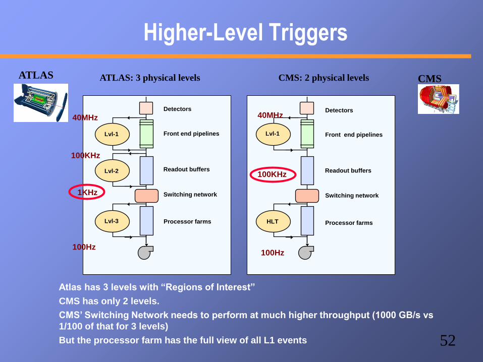
Higher-Level Triggers
Front end pipelines
Readout buffers
Processor farms
Switching network
Detectors
Lvl-1
HLT
Lvl-1
Lvl-2
Lvl-3
Front end pipelines
Readout buffers
Processor farms
Switching network
Detectors
ATLAS: 3 physical levels CMS: 2 physical levels
Atlas has 3 levels with “Regions of Interest”
CMS has only 2 levels.
CMS’ Switching Network needs to perform at much higher throughput (1000 GB/s vs
1/100 of that for 3 levels)
But the processor farm has the full view of all L1 events
40MHz
100KHz
1KHz
40MHz
100KHz
100Hz100Hz
ATLAS CMS
53
PHENIX DAQ Event builder
ATP
ATP
ATP
ATP
ATP
ATP
ATP
ATP
ATP
ATP
SEB
SEB
SEB
SEB
SEB
SEB
SEB
SEB
SEB
SEB
10Gigabit
Crossbar
Switch
To
Tape
Event BuilderBuffer Box
Buffer Box
Buffer Box
Buffer Box
Buffer Box
Buffer Box
Buffer Box
FEM
FEM
FEM
FEM
FEM
FEM
FEM
FEM
FEM
FEM
DCM
DCM
DCM
DCM
DCM
Partition
Mod.
Partition
Mod.
Front-End Module
Digitizes data
Data Collection Module
Zero-Suppression,
packaging
Partition Module and Sub-Event
Buffer
Combines data from several DCMs
Assembly and Trigger Processor
Builds full events
Buffer Box
Buffers data O(40h) - steady data
stream for the tape robot
54
PHENIX DAQ
ATP
ATP
ATP
ATP
ATP
ATP
ATP
ATP
ATP
ATP
SEB
SEB
SEB
SEB
SEB
SEB
SEB
SEB
SEB
SEB
10Gigabit
Crossbar
Switch
To
Tape
Event BuilderBuffer Box
Buffer Box
Buffer Box
Buffer Box
Buffer Box
Buffer Box
Buffer Box
FEM
FEM
FEM
FEM
FEM
FEM
FEM
FEM
FEM
FEM
DCM
DCM
DCM
DCM
DCM
Partition
Mod.
Partition
Mod.
55
Multi-Event Buffering aka pipelining
PHENIX is a rare-event
experiment, after all --
you don’t want to go
down this path
Without MEB
56
MEB: trigger delays by analog Memory
trigger electronics needs to buy some time to make its decision
done by storing the signal charge in an analog memory (AMU)
Memory keeps the state of some 40us worth of bunch crossings
Trigger decision arrives. FEM goes back a given number of analog memory
cells and digitizes the contents of that memory location
timeMulti-Event buffering means to start the AMU sampling again while the
current sample is still being digitized.
Trigger busy released much earlier
deadtime greatly reduced
57
The Multi-Event Buffering Effect
58
FPGAs, FPGAs, and Networks
•I believe that the typical physicist will be able to program FPGAs and know VHDL just like
we all know C++ these days
•We already see FPGAs enter the commodity HPC market (driven by $$$ or course)
•That, and networks will drive most DAQs
•We already see this in the (F)VTX readout – the entire front-end is FPGAs
•A well-designed board can be used for an astonishing variety of things.
DCM2 +
Partitioner 2
59
Controls
•At some point, you need to add controls (usually called slow controls) to
your setup.
•Control the data taking
•Control and configure the front-end
•Set High Voltages, bias voltages, magnetic fields, etc
•If you are a BIG experiment (think LHC), there's a comprehensive solution
•If you rig up something smaller, you are typically on your own
•Also think of the need to log all such data
60
Communication methods
If you work for an LHC experiment, this is all taken care of for you.
If not, well, some pointers.
These are some methods to communicate between processes on a machine
SharedMemory
NamedSemaphores
RemoteProdecure
CallsCORBA
These work only on the same machine
(yes, there are add-ons to get around
that, but it's a bit of a kludge)
Few people use shared memory any more.
These work in a network-transparent fashion
If I want, I can control my DAQ at BNL from here
61
RPC
•Remote Procedure Call
•Widely established standard (RFC 1831) for remote execution of code controlled by a
client
•Makes it look like a local function call, but the function executes on a server
•The ubiquitous NFS is based on RPC, it is available virtually everywhere
•It is a network protocol, so client and server don't have to be on the same machine,
can have DAQ and control machine in different rooms (or as far apart as you like as
long as the connection traverses the firewalls)
•Very robust and easy, and an open standard built into virtually any OS
•Linux, Android, Windows, …. works on any Linux flavor, for example the Raspberry
PI
62
CORBA
•Attempt to take a C-style remote procedure call (like a function call) to
calling methods on a remote object
•Fundamentally a good idea, but in many cases overkill and really
complicated to implement
•Not very widespread availability
•No good “vendor” (it's usually open source, but different implementations)
interoperability (supposed to be, but not so)
I'm using RPCs unless there's a good reason not to.
My first choice.
63
Log. Log. And log some more
Everyone has used a paper logbook. In this day and age, this is not an adequate
solution anymore.
I'm talking about “environmental” data logging here, the logging of “slow controls”
data
I will use a DAQ of mine as an example, but this goes for all setups.
64
Logging data about the data
•“reading out your detector” does not yet make a data acquisition
•It lives and dies by its ability to capture... well, everything
•What was the HV? Was the light on? What was the temperature?
•In many cases, it's there only for forensics in case there's something wrong
•Was the HV where it was supposed to be?
•Often, you need to get parameters which in the old days you had to type in from a
paper logbook
•You could add a webcam picture so we have a visual confirmation of things (say,
you want to move the detector with step motors)
•When you log these things automatically, no one can forget to do it.
65
Metadata Example
“It appears that the distributions changes for Cherenkov counter 1 at 1,8,12,and
16 GeV compared to the other energies. It seems that the pressure is changed.
[…] Any help on understanding this would be appreciated.”
Martin: “Look at the info in the file!”
$ ddump -t 9 -p 910 beam_00002298-0000.prdf
S:MTNRG = -1 GeV
F:MT6SC1 = 5790 Cnts
F:MT6SC2 = 3533 Cnts
F:MT6SC3 = 1780 Cnts
F:MT6SC4 = 0 Cnts
F:MT6SC5 = 73316 Cnts
E:2CH = 1058 mm
E:2CV = 133.1 mm
E:2CMT6T = 73.84 F
E:2CMT6H = 32.86 %Hum
F:MT5CP2 = .4589 Psia
F:MT6CP2 = .6794 Psia
$ ddump -t 9 -p 910 beam_00002268-0000.prdf
S:MTNRG = -2 GeV
F:MT6SC1 = 11846 Cnts
F:MT6SC2 = 7069 Cnts
F:MT6SC3 = 3883 Cnts
F:MT6SC4 = 0 Cnts
F:MT6SC5 = 283048 Cnts
E:2CH = 1058 mm
E:2CV = 133 mm
E:2CMT6T = 74.13 F
E:2CMT6H = 37.26 %Hum
F:MT5CP2 = 12.95 Psia
F:MT6CP2 = 14.03 Psia
66
A picture tells more that 1000 words
Was XXXx's contraption in the beam in run 2743? There is a higher fraction of showering than before.”Martin: “Look at the cam pictures we automatically captured for each run.”