61
Cabling a Data Center to TIA-942 Standard BICSI 2006 Winter Conference Wednesday, January 25 th 2006 at 9:15 am Gary J. Bernstein, RCDD HellermannTyton Corporation
| Date post: | 29-Oct-2015 |
| Category: |
Documents |
| Upload: | gonzalo-prado |
| View: | 164 times |
| Download: | 37 times |

Cabling a Data Center to TIA-942 Standard
BICSI 2006 Winter ConferenceWednesday, January 25th 2006 at 9:15 am
Gary J. Bernstein, RCDDHellermannTyton Corporation

Agenda
• Overview of TIA-942 Data Center Standard• How is a data center defined?• Who is the standard for?• How can the standard help you better design your
infrastructure?• Cabling media options• Examples of typical applications

Summary of TIA-942
• Purpose is to provide requirements and guidelines for the DESIGN and INSTALLATION of a data center or computer room
• Will enable design to be involved early in construction process
• Allow for long term planning of data centers to support growth and future applications

Outline of Standard
• Design• Cabling System Infrastructure• Telecommunications Spaces & Topologies• Cabling Systems• Cabling Pathways• Redundancy• Informative Annexes

What is a data center?• “A building or portion of a building whose primary function is
to house a computer room and it’s support areas”

Types of Data Centers
• Private Domain or Enterprise
• Public Domain

Data Center Design• Coordination of all aspects of a data center is
critical including:– Telecommunications cabling system– Equipment floor plan– Electrical plans– Architectural plan– HVAC– Security– Lighting system

Recommended Design Process
• Estimate needs at full capacity for all equipment• Anticipate future growth over life of data center• Provide all requirements to architects and engineers• Create an equipment floor plan• Design telecommunications cabling system

Computer Room
NOC TR(s) serving DC spaces
StorageRooms & Loading Docks
Support StaffEntrance Room(s)
DC Electrical &Mechanical Rooms
General Office Space
TR’s & ER’s Serving spaces outside DC
Data Center
Building ShellBuilding Site
Relationship of spaces in a data center

Data Center Tiers
• Relates to levels of availability of infrastructure• Tier Classifications were originally defined by The
Uptime Institute• Addresses critical systems of data center• Critical systems may have different ratings• Ratings can be degraded as data center load increases
over time

Tier I - Basic
• Single path for power and cooling distribution• No redundant components• May not have a raised floor• Susceptible to disruption from planned and
unplanned activity• 28.8 hours of annual downtime

Tier II – Redundant Components
• Single path for power and cooling distribution• Redundant components• Has a raised floor• Slightly less susceptible to disruptions than Tier I• 22.0 hours of annual downtime

Tier III – Concurrently Maintainable
• Multiple power and cooling distribution paths– Only one active path
• Redundant Components• Allows for any planned site infrastructure activity
without disrupting computer hardware operation• 1.6 hours of annual downtime

Tier IV – Fault Tolerant
• Multiple active power and cooling distribution paths• Redundant components• All computer hardware must have dual power inputs • Can sustain at least one worst-case, unplanned failure
or event with no critical load impact• 0.4 hours of annual downtime

TIA-942 Defines Critical Systems
• Telecommunications*• Architectural and Structural• Electrical• Mechanical

Tier 1 – Telecommunications Requirements
• Cabling, racks, cabinets & pathways meet TIA-942 requirements
• Has 1 entrance pathway from access provider to facility• Single pathway for all cabling• Recommended labeling per ANSI/TIA/EIA-606-A and
Annex B

Tier 2 – Telecommunications Requirements
• All requirements of Tier 1• Has 2 entrance pathways from access provider to
facility • Routers & switches to have redundant power supplies
and processors• Addresses vulnerability of service entering building
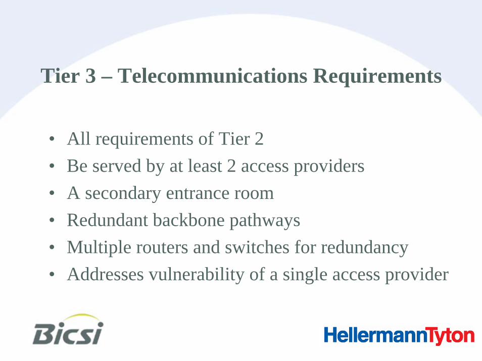
Tier 3 – Telecommunications Requirements
• All requirements of Tier 2• Be served by at least 2 access providers• A secondary entrance room• Redundant backbone pathways• Multiple routers and switches for redundancy• Addresses vulnerability of a single access provider

Tier 4 – Telecommunications Requirements
• All requirements of Tier 3• Redundant backbone cabling • Backbone cabling should be in conduit or have
interlocking armor• Optional secondary distribution area • Optional redundant horizontal cabling• Address any vulnerability of the cabling infrastructure

Telecommunications Spaces
• Entrance Room (ER)• Main Distribution Area (MDA)• Horizontal Distribution Area (HDA)• Zone Distribution Area (ZDA)• Equipment Distribution Area (EDA)

Example of basic data center topology from TIA-942

Entrance Room
• Access provider demarcation point• Termination equipment for access provider cables• Interface between data center cabling and inter-
building cabling• Pathways for all entrance cables• May be located inside or outside computer room

Main Distribution Area
• Central point of distribution • Includes the main cross-connect
(MC)• May include horizontal cross-
connect (HC)• Core routers & switches for
LAN/SAN, PBX are located here• Located inside computer room• Must be at least one MDA

Horizontal Distribution Area
• Supports all the cabling to the equipment distribution areas
• Includes the horizontal cross-connect (HC)
• Switches for equipment in EDA located here
• Located inside computer room• Minimum of one HDA per floor

Zone Distribution Area• Optional inter-connection point within
horizontal cabling • Located between HDA and EDA• Allows frequent reconfiguration and
flexibility• Should serve a maximum of 288
connections to avoid cable congestion• Shall be no active equipment (except for
DC power)

Equipment Distribution Area
• Space for end equipment:– Servers – Mainframes– Tape Drives
• Horizontal cabling is terminated here onto patch panels
• Point-to-point cabling between equipment is allowed

Data Center Cabling System

Recognized Cabling Media
• 100-Ohm twisted-pair cable• 62.5/125 µm or 50/125 µm
multimode fiber• Singlemode fiber• 75 Ohm coaxial cable• Various options for each media
– Traditional field terminations– Pre-terminated configurations
TraditionalPre-terminated
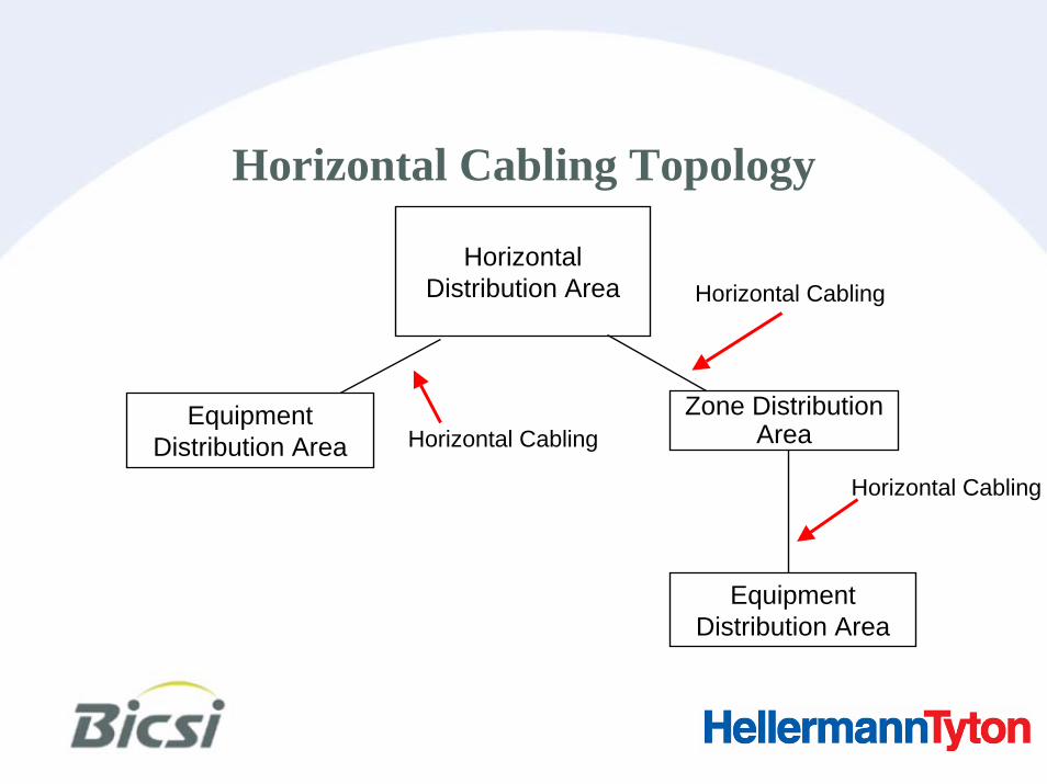
Horizontal Distribution Area
Horizontal Cabling
Zone Distribution Area
Equipment Distribution Area Horizontal Cabling
Horizontal Cabling
Equipment Distribution Area
Horizontal Cabling Topology

Horizontal Cabling
• Cabling from HDA to EDA including– Horizontal cables– Horizontal cross-connects– Patch Cords– Optional consolidation point or zone outlet
• 100 meter MAX horizontal cable distance– Distance reduced if zone area cable used

HDA EDA
FANS TA T
U S
1
2
3
4
5
6
7
8
9
P ow er S uppl y 1
P ow er S uppl y 2
Ca ta ly st 6 5 0 0
SERIES
Patch baySDTHE SIEMON COMPANY
SDTHE SIEMON COMPANY
SDTHE SIEMON COMPANY
SDTHE SIEMON COMPANY
SDTHE SIEMON COMPANY
SDTHE SIEMON COMPANY
SDTHE SIEMON COMPANY
SDTHE SIEMON COMPANY
Patch Cord into Switch
Patch Cord into Server
Switch
Servers
48-Port Patch Panels
Horizontal Cabling
Sample Application

Switch
HDA EDAZDA
FANS TA T
U S
1
2
3
4
5
6
7
8
9
P ow er S uppl y 1
P ow er S uppl y 2
Ca ta ly st 6 5 0 0
SERIES
SDTHE SIEMON COMPANY
SDTHE SIEMON COMPANY
SDTHE SIEMON COMPANY
SDTHE SIEMON COMPANY
SDTHE SIEMON COMPANY
SDTHE SIEMON COMPANY
SDTHE SIEMON COMPANY
SDTHE SIEMON COMPANY
Patch Cord into Switch
Patch Cord into Server
Servers
48-Port Patch Panels
Horizontal Cabling

Backbone Cabling Topology
TRMain
Distribution Area
Horizontal Distribution
Area
Horizontal Distribution
Area
Backbone Cabling
Backbone Cabling
Entrance Room

Backbone Cabling• Cabling between ER, MDA
and HDA including:– Backbone cables– Main cross-connects– Horizontal cross-connects– Patch cords
• Shall allow network reconfigurations and future growth

Cabling Pathways
• Data Centers shall adhere to ANSI/TIA-569-B specifications with exceptions noted in standard
• Cabling shall not be routed through public spaces unless enclosed in secure pathways
• Maintenance holes, pull boxes, splice boxes shall be locked and monitored

Cabling Pathways – Separation of Cabling
• Proper distances must be maintained between electrical and twisted pair cables
• Branch electrical circuits should be in watertight flexible metal conduit
• Feeder electrical circuits to power distribution units should be in solid metal conduit
• If using cable tray – MINIMUM of 12” between trays

Cabling Pathways – Separation of Cabling
Access Floors• Allocate separate aisles for power and
telecommunications cabling• If not possible, then provide both horizontal and
vertical separation

Cabling Pathways – Separation of Cabling
Cable Trays• Fiber and copper cabling in trays should be
separated:– Improves administration– Minimizes damage to smaller diameter cables– If possible, fiber should be on top of copper

Cabling Pathways – Entrance Room
• Should all be underground
• Each Access Provider should have at least one 4”conduit
• Shall meet ANSI/TIA-569-B

Cabling Pathways – Access Floors
• Cabling under floor shall be in ventilated cable trays
• Trays may be installed in multiple layers• Trays shall have a maximum depth of 6”• Access floor should use bolted stringer
structure• Plenum rated cable is typical – consult
AHJ

Cabling Pathways – Overhead Cable Trays
• Trays may be installed in multiple layers• Trays shall have a maximum depth of 6”• In shared-tenant data center common
spaces:– Solid bottom tray OR– MIN of 9 ft above finished floor
• Tray should be supported from ceiling

Redundancy
• Reliability of telecommunications infrastructure needs to be increased – Defined by Tier ratings
• Very common to have multiple Service Providers• Entrance Pathways should be on opposite ends of building• If secondary ER required:
– Access provider equipment should be able to operate independently– 20 meters of separation– Separate fire protection zones

Redundancy – Main Distribution Area
• If secondary distribution required:– Core routers and switches should be distributed– Circuits should be split – Separate fire protection zones– Separate power distribution units– Separate air conditioning systems

MDA(Primary)
SDA(Redundant)
HDA
HDA ZDA
EDA
EDA
EDA
Infrastructure Redundancy

Redundancy – Backbone Cabling
• Protects against outage caused by damage• Common to see additional cabling
– MDA to HDA– HDA to HDA
• Cabling should be run along different routes• If secondary distribution area
– Not required HDA to HDA

Redundancy – Horizontal Cabling
• Cabling should be run along different routes• Still must meet 100 meter maximum cable lengths • Critical equipment can be supported by 2 HDA’s
– Separate fire protection zones

Informative Annex B
Identification of Cabling Infrastructure
• Data Centers should adhere to ANSI/TIA/EIA-606-A with exceptions as noted in standard

Identification Scheme for Floor Space
• Floor space should track the data center grid
• Use two letters and two numeric digits to identify each 600mm x 600mm (2ft X 2ft) floor tile
• AA, AB, AC…AZ, BA, BB, BC…and so on

Sample Floor Space IdentifierAEAA AD AF AG AH AI AJ AK AL AM ANACAB
“Y” Coordinate
01
03
04
06
07
08
09
10
11
12
13
02
05
“X” Coordinate

Identification Scheme for Racks and Cabinets
• All racks and cabinets should be labeled front and back
• For rooms with access floors, each rack and cabinet to have a unique identifier based on floor tile coordinates
• If cabinet rests on more than one tile, the same corner of each cabinet can be used to identify the grid location– Example: Front right corner

“X” Coordinate
Sample Cabinet Identifier: AJO5
AA AD AE AF AG AH AI AJ AK AL AM ANACAB
“Y” Coordinate
Sample CabinetRight Front Corner
01
03
04
06
07
08
09
10
11
12
13
02
05

Identification Scheme for Racks and Cabinets
• In data centers with multiple floors, the floor number should be added as a prefix to the cabinet number
• EXAMPLE: A cabinet whose right front corner is at tile AJ05 on floor 2, will be named:
2AJO5

Identification Scheme for Patch Panels
• Each panel to be labeled with an alpha character starting with A, B, C…Z etc. Starting from the top of the rack down
• Horizontal wire management panels do not count when determining patch panel position

Sample of Panel Identifiers on Rack
1 2 3 4 5 6 7 8 9 10 11 12 13 14 15 16 17 18 19 20 21 22 23 24
1 2 3 4 5 6 7 8 9 10 11 12 13 14 15 16 17 18 19 20 21 22 23 24
1 2 3 4 5 6 7 8 9 10 11 12 13 14 15 16 17 18 19 20 21 22 23 24
1 2 3 4 5 6 7 8 9 10 11 12 13 14 15 16 17 18 19 20 21 22 23 24
1 2 3 4 5 6 7 8 9 10 11 12 13 14 15 16 17 18 19 20 21 22 23 24
1 2 3 4 5 6 7 8 9 10 11 12 13 14 15 16 17 18 19 20 21 22 23 24
A
F
E
D
C
B
AJ05-A to AQ 03-B Ports 01-24
AJ05-C to AQ03-D Ports 01-24
AJ05-E to AQ 03-F Ports 01-24
AJ05-D to AQ 03-E Ports 01-24
AJ05-B to AQ 03-C Ports 01-24
AJ05-F to AQ03-G Ports 01-24

“Y” Coordinate
Sample Patch Panel Identifiers
“X” Coordinate
01
03
04
05
06
07
08
09
10
11
12
13
02
AE AG AK AM AOAA AD AF AH AI AJ AL ANACAB AP AQ AR AS AYAT AU AV AW AX
Right Front Corner
Right Front Corner
Sample Cabinet
CAT 6 x 24

Patch Panel Identifier
• Near end cabinet location and panel identifier to be followed by the far end cabinet location and panel identifier + port numbers
AJ05-A to AQ03-B Ports 1-24

Sample of Patch Panel Identifier

Cable and Patch Cord Identifier
• Cables and patch cords should be labeled on both ends with the location of both ends of the cable
• Example of the near end cable label:
AJ05-A01 / AQ03-B01
• Example of the far end cable label:
AQ03-B01 / AJ05-A01
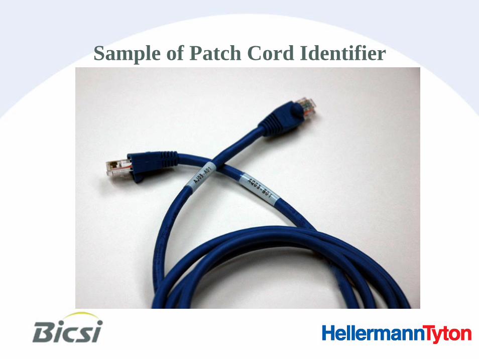
Sample of Patch Cord Identifier

Sample of Cable Identifier

Summary
• Builds off of several existing TIA standards• Focuses on specific needs and applications of data
center environment• Recommends best design and cabling practices• Recommends different cabling media options• Useful tool for design and installation of a data
center environment


