2003 ACCESSORIES & EQUIPMENT Data Link Communications - Silverado & Sierra SPECIFICATIONS FASTENER TIGHTENING SPECIFICATIONS Fig. 1: Fastener Tightening Specifications Courtesy of GENERAL MOTORS CORP. SCHEMATIC AND ROUTING DIAGRAMS DATA LINK COMMUNICATIONS SCHEMATIC ICONS Fig. 2: Data Link Communications Schematic Icons Courtesy of GENERAL MOTORS CORP. DATA LINK CONNECTOR (DLC) SCHEMATICS
Transcript
2003 ACCESSORIES & EQUIPMENT
Data Link Communications - Silverado & Sierra
SPECIFICATIONS
FASTENER TIGHTENING SPECIFICATIONS
Fig. 1: Fastener Tightening Specifications Courtesy of GENERAL MOTORS CORP.
SCHEMATIC AND ROUTING DIAGRAMS
DATA LINK COMMUNICATIONS SCHEMATIC ICONS
Fig. 2: Data Link Communications Schematic Icons Courtesy of GENERAL MOTORS CORP.
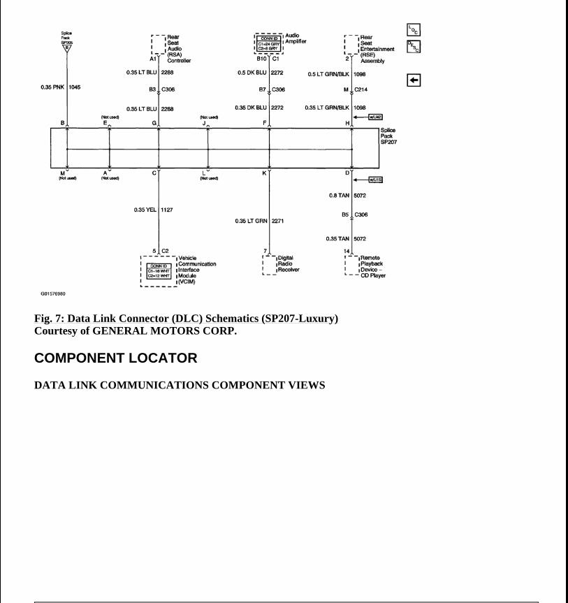
DATA LINK CONNECTOR (DLC) SCHEMATICS
2003 Chevrolet Silverado 1500
2003 ACCESSORIES & EQUIPMENT Data Link Communications - Silverado & Sierra
2003 Chevrolet Silverado 1500
2003 ACCESSORIES & EQUIPMENT Data Link Communications - Silverado & Sierra
DIAGNOSTIC STARTING POINT-DATA LINK COMMUNICATIONS
Begin the diagnosis of the Data Link Communications by performing the Diagnostic System Check for the system in which the customer concern is apparent.
The Diagnostic System Check will direct you to the correct procedure within the Data Link Communications section when a communication malfunction is present.
DIAGNOSTIC TROUBLE CODE (DTC) LIST
2003 Chevrolet Silverado 1500
2003 ACCESSORIES & EQUIPMENT Data Link Communications - Silverado & Sierra
Fig. 15: DTC Chart Courtesy of GENERAL MOTORS CORP.
DTC U1000 AND U1255
Circuit Description
Modules connected to the class 2 serial data circuit monitor for serial data communications during normal vehicle operation. Operating information and commands are exchanged among the modules. When a module receives a message for a critical operating parameter, the module records the identification number of the module which sent the message for State of Health monitoring. A critical operating parameter is one which, when not received, requires that the module use a default value for that parameter. When a module does not associate an identification number with at least one critical parameter within about five seconds of beginning serial data communication, DTC U1000 or U1255 is set. When more than one critical parameter does not have an identification number associated with it, the DTC will only be reported once. The class 2 serial data line on this vehicle is a ring/star configuration. The following modules communicate on the class 2 serial data line:
The body control module (BCM) The digital radio receiver The driver door module (DDM) The electronic brake control module (EBCM) The front passenger door module (FPDM) The HVAC control module The inflatable restraint sensing and diagnostic module (SDM) The instrument panel cluster (IPC) The memory seat module (MSM) The powertrain control module (PCM) The radio The radio amplifier The rear seat audio (RSA) controller The rear seat entertainment (RSE) assembly w/U42 The rear wheel steering control module The remote playback device-CD player w/U1S The transfer case shift control module The transmission control module (TCM) w/Allison transmission The theft deterrent control module The vehicle communication interface module (VCIM) w/UE1
Conditions for Running the DTC
Voltage supplied to the module is in the normal operating voltage range of 9-16 volts. DTCs U1300, U1301 or U1305 do not have a current status.
2003 Chevrolet Silverado 1500
2003 ACCESSORIES & EQUIPMENT Data Link Communications - Silverado & Sierra
The vehicle power mode requires serial data communication to occur.
Conditions for Setting the DTC
A node alive message has not been received from an unidentified module within the last 5 seconds after establishing class 2 serial data communication.
Action Taken When the DTC Sets
The module uses a default value for the missing parameter.
Conditions for Clearing the DTC
A current DTC clears when the malfunction is no longer present. A history DTC clears when the module ignition cycle counter reaches the reset threshold, without a repeat of the malfunction.
Diagnostic Aids
When a malfunction occurs while modules are communicating, a lost communication DTC is set as a current DTC. When the modules stop communicating the current lost communication DTC is cleared but the history DTC remains. When the modules begin to communicate again, the module with the open fuse will not be learned by the other modules so U1000 or U1255 is set current by the other modules. If the malfunction occurs when the modules are not communicating, only U1000 or U1255 is set.
Test Description
The numbers below refer to the step numbers on the diagnostic table.
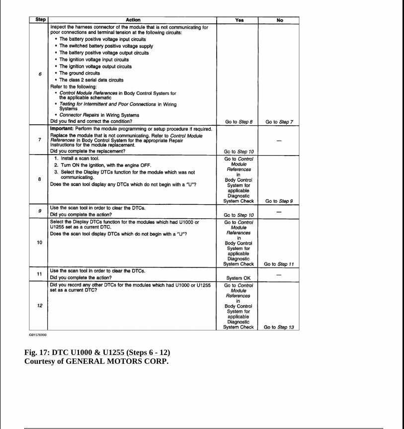
1. A DTC U1001-U1254 Lost Communications with XXX with a history status may indicate the cause of U1000 or U1255. 2. The modules not communicating are the likely cause of U1000 or U1255. The modules that are available on the class 2 serial data circuit are listed in the Circuit Description. 6. The module which was not communicating due to a poor connection to the class 2 serial data circuit may have set DTC U1001-U1254 Lost Communications with XXX for those modules that it was monitoring. 9. The modules which can communicate indicate the module which cannot communicate. You must clear the serial data communication DTCs from these modules to avoid future misdiagnosis. 12. If all modules are communicating, the module which set U1000 or U1255 may have done so due to some other condition. 14. The module which set U1000 or U1255 is the likely cause of the malfunction.
2003 Chevrolet Silverado 1500
2003 ACCESSORIES & EQUIPMENT Data Link Communications - Silverado & Sierra
Fig. 18: DTC U1000 & U1255 (Steps 13 - 14) Courtesy of GENERAL MOTORS CORP.
DTC U1001-U1254
Circuit Description
Modules connected to the class 2 serial data circuit monitor for serial data communications during normal vehicle operation. Operating information and commands are exchanged among the modules. When a module receives a message for a critical operating parameter, the module records the identification number of the module which sent the message for state of health monitoring/node alive messages. A critical operating parameter is one which, when not received, requires that the module use a default value for that parameter. Once an identification number is learned by a module, it will monitor for that modules node alive message. Each module on the class 2 serial data circuit is required to send a Node Alive message every 2 seconds. When no message is detected from a learned identification number for 5 seconds, a DTC U1XXX. XXX is equal to the 3 digit identification number of the module.
The control module ID number list provides a method for determining which module is not communicating. A module with an internal class 2 serial data circuit malfunction or which loses power during the current ignition cycle would have a lost communication DTC set by other modules. Use the control module ID number list in order to determine which module is not communicating and the lost communications with XXX diagnostic table in order to diagnose the malfunction. When no message is detected from a learned identification number for 5 seconds, a DTC U1XXX is set.
2003 Chevrolet Silverado 1500
2003 ACCESSORIES & EQUIPMENT Data Link Communications - Silverado & Sierra
Fig. 20: DTC U1001 & U1254 (2 Of 2) Courtesy of GENERAL MOTORS CORP.
When more than one loss of communication DTC is set in a single module or among multiple modules, diagnose the DTCs in the following order:
1. Current DTCs before history DTCs except as specified in the diagnostic tables. 2. The DTC which is reported the most times. 3. From the lowest number DTC to the highest number DTC.
Conditions for Running the DTC
Voltage supplied to the module is in the normal operating voltage range of 9-16 volts.
2003 Chevrolet Silverado 1500
2003 ACCESSORIES & EQUIPMENT Data Link Communications - Silverado & Sierra
DTCs U1300, U1301 or U1305 do not have a current status. The vehicle power mode requires serial data communication to occur.
Conditions for Setting the DTC
A node alive message has not been received from an unidentified module within the last 5 seconds after establishing class 2 serial data communication.
Action Taken When the DTC Sets
The module uses a default value for the missing parameter.
Conditions for Clearing the DTC
A current DTC clears when the malfunction is no longer present. A history DTC clears when the module ignition cycle counter reaches the reset threshold, without a repeat of the malfunction.
Diagnostic Aids
An intermittent open between a module and a star connector may cause this DTC to set. A poor connection at a module or a star connector may cause this DTC to set. An intermittent open in a star connector may cause this DTC to set. An open voltage or ground circuit to a module may cause this DTC to set. An internal module malfunction may cause this DTC to set.
Test Description
The number below refers to the step number on the diagnostic table.
1. 6. The module which was not communicating on the class 2 serial data circuit may have set Loss of Communication DTCs for those modules that it was monitoring.
2003 Chevrolet Silverado 1500
2003 ACCESSORIES & EQUIPMENT Data Link Communications - Silverado & Sierra
Fig. 22: DTC U1001-U1254 (Steps 4 - 8) Courtesy of GENERAL MOTORS CORP.
DTC U1300, U1301, OR U1305
Circuit Description
Modules connected to the class 2 serial data circuit monitor for serial data communications during normal vehicle operation. Operating information and commands are exchanged among the modules. Node Alive messages are transmitted by each module on the class 2 serial data circuit about once every 2 seconds. When the module detects one of the following conditions on the class 2 serial data circuit for approximately 3 seconds, the setting of all other class 2 serial communication DTCs is inhibited and a DTC will set.
2003 Chevrolet Silverado 1500
2003 ACCESSORIES & EQUIPMENT Data Link Communications - Silverado & Sierra
Fig. 23: DTC U1300, U1301 Or U1305 Courtesy of GENERAL MOTORS CORP.
Conditions for Running the DTCs
Voltage supplied to the module is in the normal operating voltage range. The vehicle power mode requires serial data communication to occur.
Conditions for Setting the DTCs
No valid messages are detected on the class 2 serial data circuit. The voltage level detected on the class 2 serial data circuit is under one of the following conditions:
High Low
The above conditions are met for approximately 3 seconds.
Action Taken When the DTCs Sets
The module inhibits the setting of all other class 2 DTCs. The module uses default values for all parameters received on the class 2 serial data circuit.
Conditions for Clearing the DTC
A current DTC clears when the malfunction is no longer present. A history DTC clears when the module ignition cycle counter reaches the reset threshold, without a repeat of the malfunction.
Diagnostic Aids
These DTCs cannot be retrieved with a current status. Diagnosis of current DTCs is accomplished via the symptom. Refer to Scan Tool Does Not Communicate With Class 2 Device . An intermittent condition is likely to be caused by a short or an open on the class 2 serial data circuit. Use the Scan Tool Does Not Communicate With Class 2 Device procedure in order to isolate an intermittent condition.
SYMPTOMS-DATA LINK COMMUNICATIONS
IMPORTANT: The following steps must be completed before using the symptom tables:
2003 Chevrolet Silverado 1500
2003 ACCESSORIES & EQUIPMENT Data Link Communications - Silverado & Sierra
1. Perform the Diagnostic System Check for the subsystem exhibiting the symptoms. The subsystem diagnostic system check will identify where to begin diagnosis of the data link communication system.
2. Review the system operation in order to familiarize yourself with the system functions. Refer to Data Link Communications Description And Operation .
Visual/Physical Inspection
Inspect for aftermarket devices that could affect the operation of the serial data communications systems. Refer to CHECKING AFTERMARKET ACCESSORIES . Inspect the easily accessible systems or visible system components for obvious damage or conditions that could cause the symptom.
Intermittent
Faulty electrical connections or wiring may be the cause of intermittent conditions. Refer to TESTING FOR INTERMITTENT AND POOR CONNECTIONS .
Symptom List
Refer to a symptom diagnostic procedure from the following list in order to diagnose the symptom:
Scan Tool Does Not Power Up Scan Tool Does Not Communicate With Class 2 Device
SCAN TOOL DOES NOT POWER UP
Circuit Description
The data link connector (DLC) is a standardized 16 cavity connector. Connector design and location is dictated by an industry wide standard, and is required to provide the following:
Scan tool power battery positive voltage at terminal 16. Scan tool power ground at terminal 4. Common signal ground at terminal 5.
The scan tool will power up with the ignition OFF. Some modules however, will not communicate unless the ignition is ON and the power mode master (PMM) module sends the appropriate power mode message.
Test Description
The number below refers to the step number on the diagnostic table.
1. 4. If the battery positive voltage and ground circuits of the DLC are functioning properly. The malfunction must be due to the scan tool.
2003 Chevrolet Silverado 1500
2003 ACCESSORIES & EQUIPMENT Data Link Communications - Silverado & Sierra
Fig. 24: Scan Tool Does Not Power Up Courtesy of GENERAL MOTORS CORP.
SCAN TOOL DOES NOT COMMUNICATE WITH CLASS 2 DEVICE
Circuit Description
Modules connected to the class 2 serial data circuit monitor for serial data communications during normal vehicle operation. Operating information and commands are exchanged among the modules. Connecting a scan tool to the DLC allows communication with the modules for diagnostic purposes. DTCs may be set due to this symptom and during this diagnostic procedure. Complete the diagnostic procedure in order to ensure all the DTCs are diagnosed and cleared from memory.
Diagnostic Aids
The BCM detects that the ignition is ON and sends the appropriate power mode message to the other modules. Therefore, the BCM must be connected to the DLC for any other module to communicate with the scan tool. When the class 2 serial data circuit:
2003 Chevrolet Silverado 1500
2003 ACCESSORIES & EQUIPMENT Data Link Communications - Silverado & Sierra
The numbers below refer to the step numbers on the diagnostic table.
2. A partial loss of communication in the class 2 serial data circuit uses a different procedure than a total loss of communication of the class 2 serial data circuit.
4. The following DTCs may be retrieved with a history status. These DTCs are not the cause of the present condition.
U1300 U1301 U1305
6. A State of Health DTC with a history status may be present along with a U1000 or U1255 with a current status. This indicates that the malfunction occurred when the ignition was on.
10. Normal class 2 serial data communication cannot take place until the body control module (BCM) module sends the appropriate power mode message. If the BCM does not send a wake-up message, other modules on the class 2 serial data circuit may not communicate.
12. Normal class 2 serial data communication cannot take place until the body control module (BCM) module sends the appropriate power mode message. If the BCM does not send a wake-up message, other modules on the class 2 serial data circuit may not communicate.
13. Normal class 2 serial data communication cannot take place until the body control module (BCM) module sends the appropriate power mode message. If the BCM does not send a wake-up message, other modules on the class 2 serial data circuit may not communicate.
19. If there are no current DTCs that begin with the letter "U", the communication concern has been repaired.
20. The communication concern may have prevented diagnosis of the customer complaint.
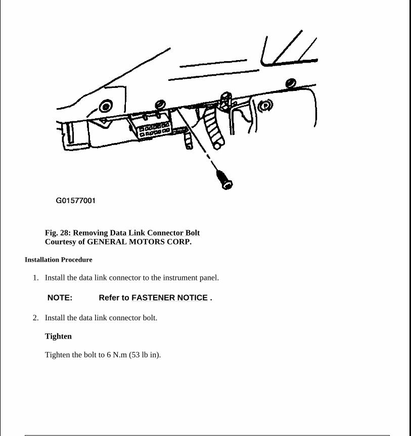
2003 Chevrolet Silverado 1500
2003 ACCESSORIES & EQUIPMENT Data Link Communications - Silverado & Sierra
Fig. 29: Installing Data Link Connector Bolt Courtesy of GENERAL MOTORS CORP.
DESCRIPTION AND OPERATION
DATA LINK COMMUNICATIONS DESCRIPTION AND OPERATION
Circuit Description
The data link connector (DLC) allows a scan tool to communicate with the class 2 serial data line. The serial data line is the means by which the microprocessor-controlled modules in the vehicle communicate with each other. Once the scan tool is connected to the class 2 serial data line through the DLC, the scan tool can be used to monitor each module for diagnostic purposes and to check for diagnostic trouble codes (DTCs). Class 2 serial data is transmitted on a single wire at an average of 10.4 kbps. This value is an average, class 2 uses a variable pulse width modulation to carry data and depending on the message it may operate faster or slower. The bus will float at a nominal 7.0 volts during normal operation. Each module can pull this lower during the transmission. The bus is not at battery positive voltage or ground potential during normal operation. When the ignition switch is in RUN, each module communicating on the class 2 serial data line sends a state of health (SOH) message every 2 seconds to ensure that the module is operating properly. When a module stops communicating on the class 2 serial data line, for example if the module loses power or ground, the SOH message it normally sends on the data line every 2 seconds disappears. Other modules on the class 2 serial data line, which expect to receive that SOH message, detect its absence; those modules in turn set an internal DTC associated with the loss of SOH of the non-communicating module. The DTC is unique to the module which is
2003 Chevrolet Silverado 1500
2003 ACCESSORIES & EQUIPMENT Data Link Communications - Silverado & Sierra
not communicating, for example, when the inflatable restraint sensing and diagnostic module (SDM) SOH message disappears, several modules set DTC U1088. Note that a loss of serial data DTC does not normally represent a failure of the module that set it.
On some vehicles, if the PCM is unable to communicate with the VTD system after the vehicle has started, the PCM will consider the VTD system to be malfunctioning. The PCM will enter a fail enable state and will command the security indicator to illuminate. When the PCM is in a fail enable state the vehicle will NOT stall or stop running. If the PCM is in a fail enable state when the ignition is switched OFF, the PCM will remain fail enable until communications with the VTD system has been restored. When the PCM is in a fail enable state the VTD system is NOT active and the vehicle will start. This feature is NOT available on all GM vehicle lines.
Data Link Connector (DLC)
The data link connector (DLC) is a standardized 16 cavity connector. Connector design and location is dictated by an industry wide standard, and is required to provide the following:
Scan tool power battery positive voltage at terminal 16. Scan tool power ground at terminal 4. Class 2 serial data at terminal 2. Common signal ground at terminal 5.
Class 2 Serial Data Line
The class 2 serial data line on this vehicle is a star configuration. The following modules communicate on the class 2 serial data line:
The body control module (BCM) The digital radio receiver The driver door module (DDM) The electronic brake control module (EBCM) The front passenger door module (FPDM) The HVAC control module The inflatable restraint sensing and diagnostic module (SDM) The instrument panel cluster (IPC) The memory seat module (MSM) The powertrain control module (PCM) The radio The radio amplifier The rear seat audio (RSA) controller The rear seat entertainment (RSE) assembly w/U42 The rear wheel steering control module The remote playback device-CD player w/U1S
2003 Chevrolet Silverado 1500
2003 ACCESSORIES & EQUIPMENT Data Link Communications - Silverado & Sierra
The transfer case shift control module The transmission control module (TCM) w/Allison Transmission The theft deterrent control module The vehicle communication interface module (VCIM) w/UE1
The class 2 serial data line allows a scan tool to communicate with these modules for testing purposes, checking for DTCs, and to activate/enable/disable functions. These class 2 serial data circuits are bussed together via splice packs and a data link connector (DLC):
SP205 SP206 SP207 DLC-connects the scan tool to the class 2 serial data circuits.
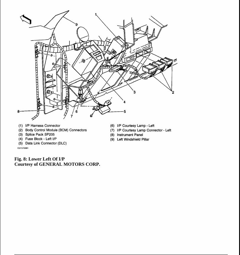
Refer to Data Link Communications Component Views for an illustrated view of the splice pack locations.
2003 Chevrolet Silverado 1500
2003 ACCESSORIES & EQUIPMENT Data Link Communications - Silverado & Sierra