1 Data and Computer Comm. Stallings – Chapter 7 Data Link Control Protocols NOTE: Many figures and other materials in this presentation are borrowed from required and reference textbooks cited on the class web page. 2 Data Link Control Protocols Flow Control
Transcript
1
Data and Computer Comm.
Stallings – Chapter 7
Data Link Control Protocols
NOTE: Many figures and other materials in this presentation are borrowed from required and reference textbooks cited on the class web page.
2
Data Link Control Protocols
Flow Control
3
Flow Control
Ensuring the sending entity does not overwhelm the receiving entity
Preventing buffer overflow
Transmission timeTime taken to emit all bits of frame onto medium
Proportional to length of frame (and data rate)
Propagation timeTime for a bit to traverse link between source and destination (a function of velocity and distance)
4
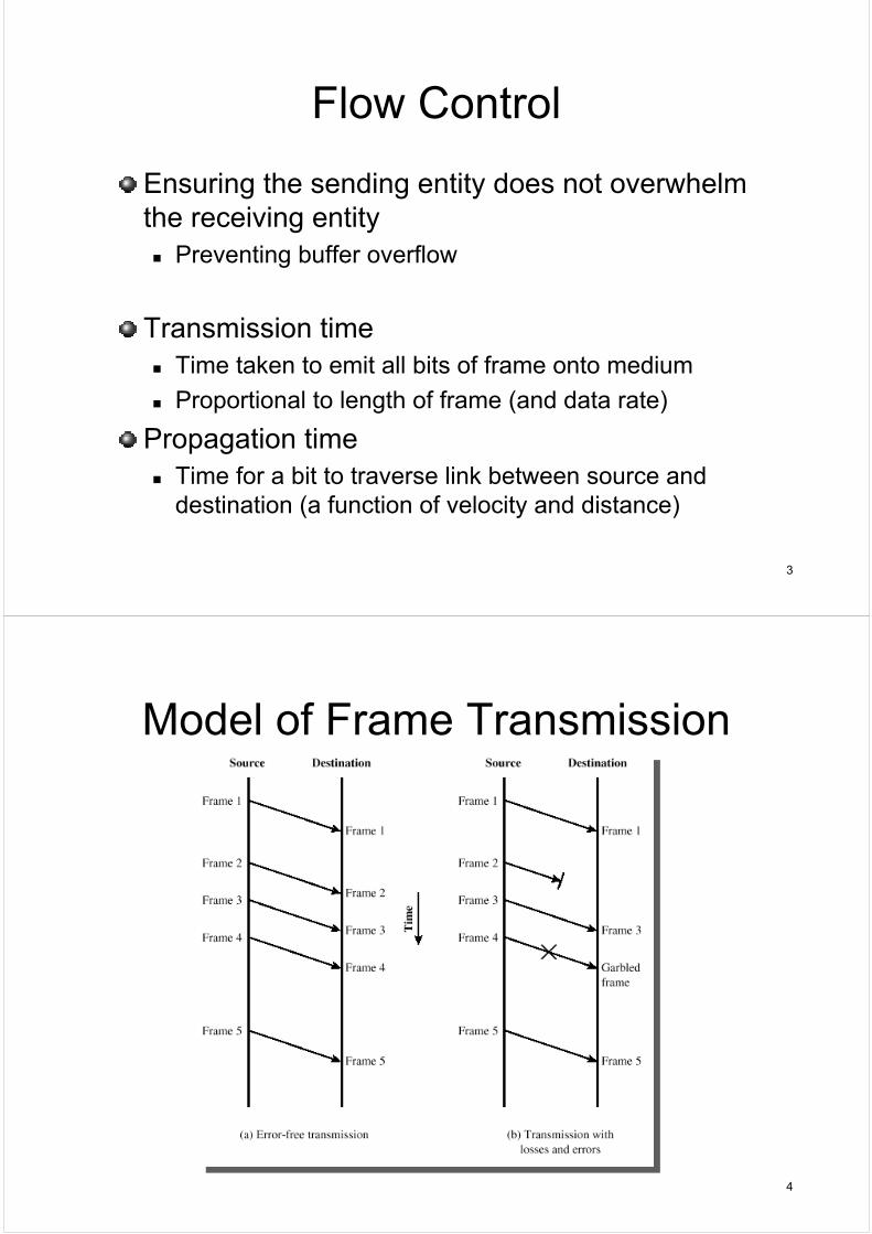
Model of Frame Transmission
5
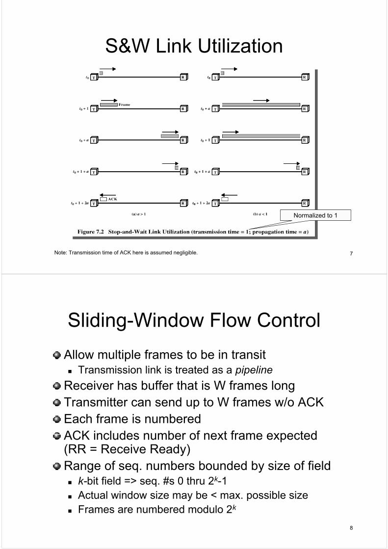
Stop-and-Wait
Simplest form of flow control
Basic behaviorSource transmits frame
Destination receives frame and replies with acknowledgement (ACK)
Source waits for ACK before sending next frame
Destination can stop flow by not sending ACK
Works well for a few large frames
6
Fragmentation
Large block of data may be split into small frames
Positive acknowledgment (from receiver on success)
Retransmission after timeout (when timer expires)
Negative acknowledgement and retransmissionInstead of making sender wait for timeout to retransmit, receiver returns NACK to frames where error detected
14
Automatic Repeat Request (ARQ)
Three versions are standardizedStop-and-Wait ARQ
Go-Back-N ARQ
Selective-Reject ARQ
Each is an extension to S&W or sliding-window schemes for flow control that we previously studied
Extended for error control
15
Stop-and-Wait ARQ
Source transmits single frameWaits for ACKIf received frame damaged, receiver discards it
Sender has timeout (equipped with a timer)If no ACK within timeout, sender retransmits
If ACK is damaged, sender will not recognize itSender will retransmitReceiver gets two copies of frameHow to solve duplication at receiver?
Frames alternately numbered with 0 or 1 by senderPositive ACKs from receiver use ACK0 and ACK1 alternately
e.g. like sliding-window, ACK0 means “#1 good, send me #0” !
Receiver recognizes duplicate and discards one
16
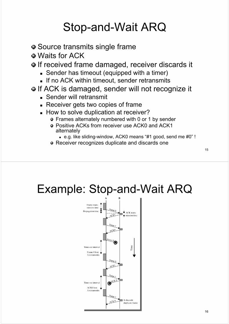
Example: Stop-and-Wait ARQ
17
Stop-and-Wait ARQ Tradeoffs
ProSimple
ConInefficient
18
Go-Back-N ARQ
Based on sliding-window flow control
Use window to control # of outstanding frames
If no error, ACK from receiver as usual with # of next frame expected (via RR or piggyback)
If error detected, reply with rejection (REJ)Destination discards that frame and all future framesuntil error frame received correctly
Source must go back and retransmit that frame and all subsequent frames
19
Several Contingencies
Go-back-N ARQ accounts for several contingencies
Damaged/lost data frame
Damaged/lost RR
Damaged/lost REJ
NoteDistinction between damaged and lost frame is minor here, since with only error detection all bits in frame are suspect
Thus, we cannot tell if damaged frame was a garbled data frame, RR, REJ, etc.
20
Damaged/lost Data FrameCase (a)
Sender transmits frame iFrame i is lost or damaged in transit
If latter, detected and discarded by receiver
Sender soon after sends i+1Receiver gets frame i+1 out of sequenceReceiver sends REJ-iSender retransmits frame i and all subsequent frames
Case (b)Frame i lost or damaged/discarded and no additional frames are sentReceiver gets nothing, returns neither ack. nor rejectionWhen sender’s timer expires, it transmits RR including special P bit set
P=1 tells destination this is a command that must be acknowledged
Receiver responds with RR-i and sender then retransmits frame iAlternative
Receiver could send REJ-x (x the next frame expected) when it discards an error frame, but receiver does not know the purpose of damaged frame and thus might be rejecting a good frame currently in flight
21
Damaged/lost RRCase (a)
Receiver gets frame i and sends RR (i + 1)
RR is lost in transit
Since acks. are cumulative, a subsequent RR for subsequent frame may arrive before sender’s timer expires on frame iThus, problem worked itself out on its own ☺
Case (b)If sender times out, it sends RR to receiver with P=1 as before
Sender sets another timer (P-bit timer)
If receiver fails to respond or response is damaged, P-bit timer expires
If so, sender again sends RR with P=1 and resets P-bit timer
This procedure can be repeated # of times before some limit is reached and reset procedure is initiated
22
Damaged/lost REJ
Same procedure as lost data frameIf sender sends more frames, REJ-i repeated
If sender does not, it times outSends RR with P=1 to receiver as before
Receiver responds with RR-iSender then retransmits frame i
23
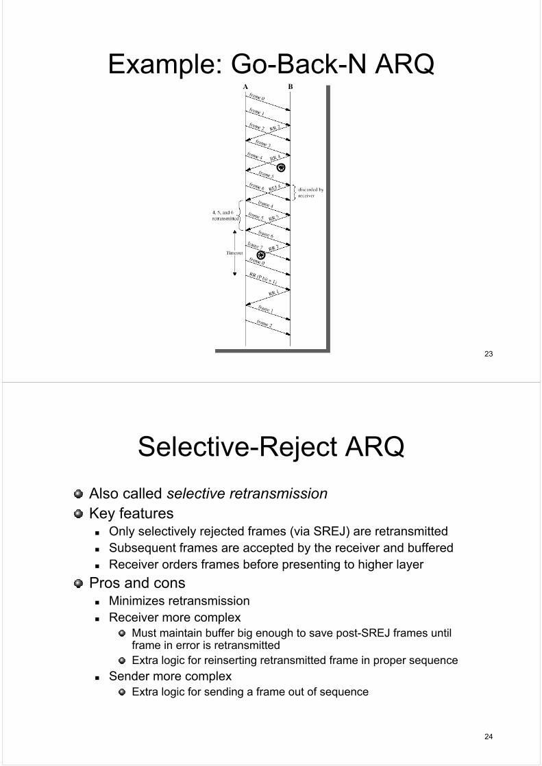
Example: Go-Back-N ARQ
24
Selective-Reject ARQ
Also called selective retransmissionKey features
Only selectively rejected frames (via SREJ) are retransmitted
Subsequent frames are accepted by the receiver and buffered
Receiver orders frames before presenting to higher layer
Pros and consMinimizes retransmission
Receiver more complexMust maintain buffer big enough to save post-SREJ frames until frame in error is retransmitted
Extra logic for reinserting retransmitted frame in proper sequence
Sender more complexExtra logic for sending a frame out of sequence
25
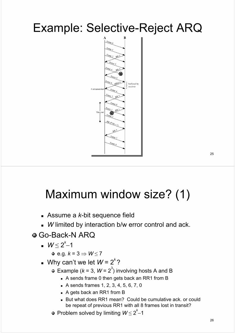
Example: Selective-Reject ARQ
26
Maximum window size? (1)
Assume a k-bit sequence field
W limited by interaction b/w error control and ack.
Go-Back-N ARQW ≤ 2
k−1e.g. k = 3 ⇒ W ≤ 7
Why can’t we let W = 2k ?
Example (k = 3, W = 23) involving hosts A and B
A sends frame 0 then gets back an RR1 from B
A sends frames 1, 2, 3, 4, 5, 6, 7, 0
A gets back an RR1 from B
But what does RR1 mean? Could be cumulative ack. or could be repeat of previous RR1 with all 8 frames lost in transit?
Problem solved by limiting W ≤ 2k−1
27
Maximum window size? (2)
Selective-Reject ARQW ≤ 2
k−1
e.g. k = 3 ⇒ W ≤ 4
Why more restricted than with GBN?Example (k = 3, W = 2
k−1) involving hosts A and B
A sends frames 0, 1, 2, 3, 4, 5, 6 to BB receives all frames then cumulatively acks. with RR7RR7 is lost in transitA times out and retransmits frame 0However, B has already advanced its window to accept next frames (7, 0, 1, 2, 3, 4, 5)Thus, upon receiving retransmitted frame 0, B assumes it is a new frame 0 and accepts it as such assuming that frame 7 must have been lost
Problem caused by overlap b/w sending and receiving windows
Solved by limiting W ≤ 2k−1
28
Data Link Control Protocols
High-Level Data Link Control (HDLC)
29
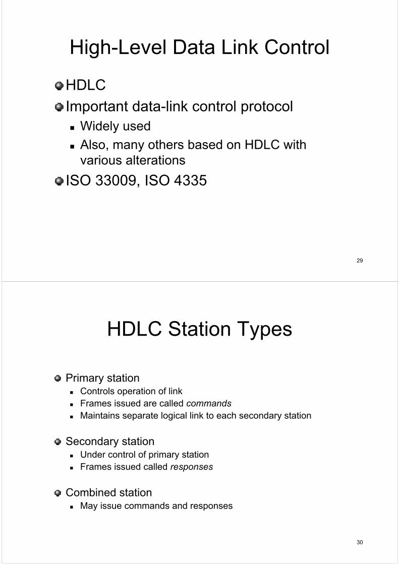
High-Level Data Link Control
HDLC
Important data-link control protocolWidely used
Also, many others based on HDLC with various alterations
ISO 33009, ISO 4335
30
HDLC Station Types
Primary stationControls operation of link
Frames issued are called commandsMaintains separate logical link to each secondary station
Secondary stationUnder control of primary station
Frames issued called responses
Combined stationMay issue commands and responses
31
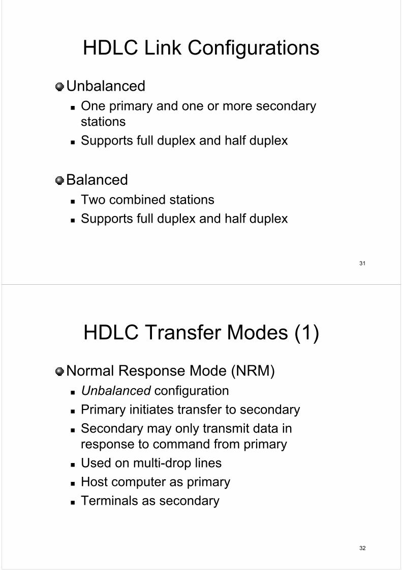
HDLC Link Configurations
UnbalancedOne primary and one or more secondary stations
Supports full duplex and half duplex
BalancedTwo combined stations
Supports full duplex and half duplex
32
HDLC Transfer Modes (1)
Normal Response Mode (NRM)Unbalanced configuration
Primary initiates transfer to secondary
Secondary may only transmit data in response to command from primary
Either station may initiate transmission without receiving permission
No polling overhead
Most widely used
35
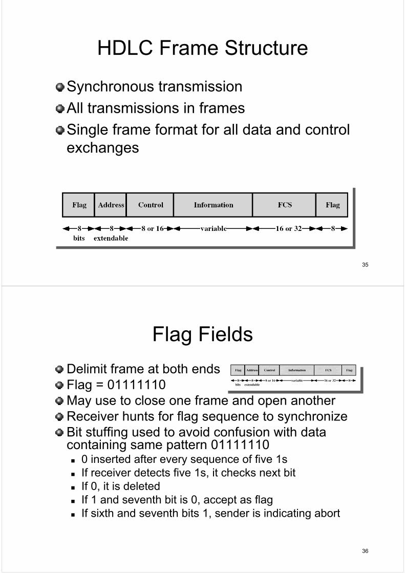
HDLC Frame Structure
Synchronous transmission
All transmissions in frames
Single frame format for all data and control exchanges
36
Flag Fields
Delimit frame at both endsFlag = 01111110May use to close one frame and open anotherReceiver hunts for flag sequence to synchronizeBit stuffing used to avoid confusion with data containing same pattern 01111110
0 inserted after every sequence of five 1sIf receiver detects five 1s, it checks next bitIf 0, it is deletedIf 1 and seventh bit is 0, accept as flagIf sixth and seventh bits 1, sender is indicating abort
37
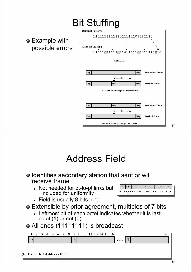
Bit Stuffing
Example with possible errors
38
Address Field
Identifies secondary station that sent or will receive frame
Not needed for pt-to-pt links but included for uniformity
Field is usually 8 bits long
Extensible by prior agreement, multiples of 7 bitsLeftmost bit of each octet indicates whether it is last octet (1) or not (0)
All ones (11111111) is broadcast
39
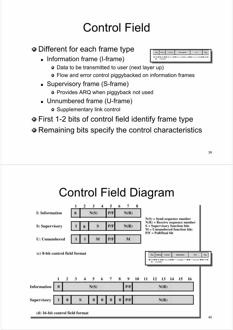
Control Field
Different for each frame typeInformation frame (I-frame)
Data to be transmitted to user (next layer up)
Flow and error control piggybacked on information frames
Supervisory frame (S-frame)Provides ARQ when piggyback not used
Unnumbered frame (U-frame)Supplementary link control
First 1-2 bits of control field identify frame type
Remaining bits specify the control characteristics
40
Control Field Diagram
41
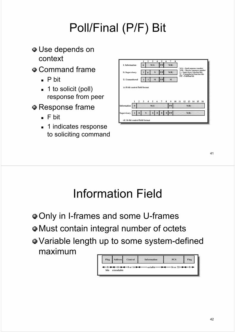
Poll/Final (P/F) Bit
Use depends on context
Command frameP bit
1 to solicit (poll) response from peer
Response frameF bit
1 indicates response to soliciting command
42
Information Field
Only in I-frames and some U-frames
Must contain integral number of octets
Variable length up to some system-defined maximum
43
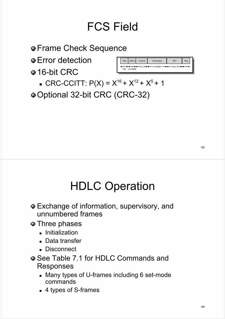
FCS Field
Frame Check Sequence
Error detection
16-bit CRCCRC-CCITT: P(X) = X16 + X12 + X5 + 1
Optional 32-bit CRC (CRC-32)
44
HDLC Operation
Exchange of information, supervisory, and unnumbered frames
Three phasesInitialization
Data transfer
Disconnect
See Table 7.1 for HDLC Commands and Responses
Many types of U-frames including 6 set-mode commands
4 types of S-frames
45
46
Examples of Operation (1)
47
Examples of Operation (2)
48
Other DLC Protocols (e.g. LLC)
Logical Link Control (LLC)IEEE 802.2Different frame format
Link control split between two sublayers, medium access layer (MAC) and LLC (on top of MAC)
No primary and secondary - all stations are peers
Two MAC addresses neededSender and receiver
Error detection at MAC sub-layer32-bit CRC
Destination and source access points (DSAP, SSAP) at LLC sub-layer
LLC control field same as HDLC but only 7-bit seq. #s