37
Data Logger For Mechanical Systems Group 2: Abdulrahman Al-Malki Faisal Al-Mutawa Mohammed Alsooj Yasmin Hussein 1
| Date post: | 02-Jan-2016 |
| Category: |
Documents |
| Upload: | charity-smith |
| View: | 221 times |
| Download: | 0 times |

Data Logger For Mechanical Systems
Group 2:Abdulrahman Al-Malki Faisal Al-Mutawa Mohammed Alsooj Yasmin Hussein 1
Outline Introduction: Abdulrahman
Overall Progress: Abdulrahman
Team Member Summary: All
Timeline and Conclusion: Mohammed
2
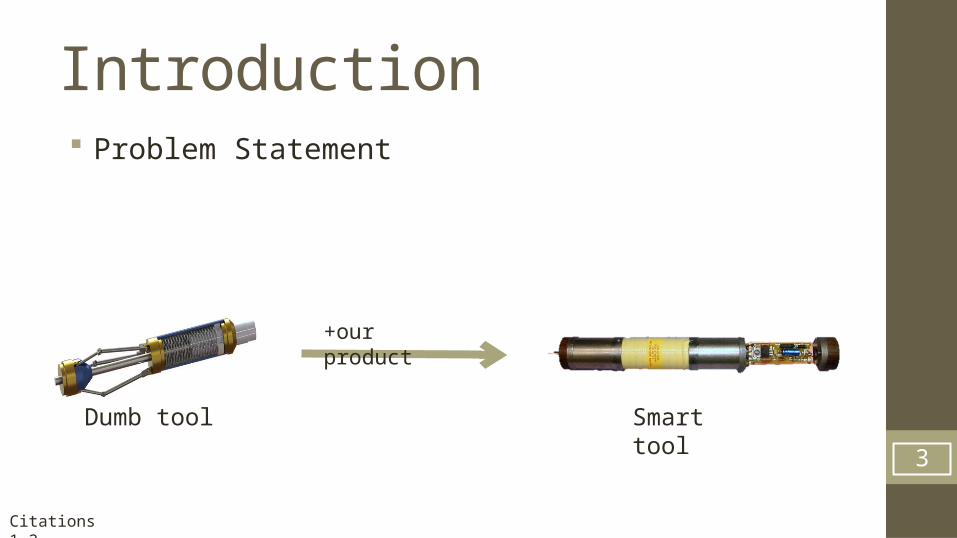
Introduction Problem Statement
3
Dumb tool Smart tool
+our product
Citations 1-2
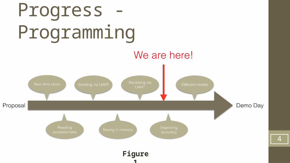
Progress - Programming
4
Figure 1
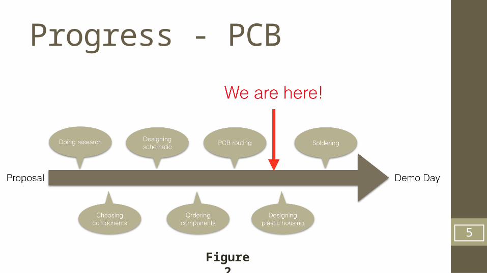
Progress - PCB
5
Figure 2
Accomplishments: Designing real-time clock Sending ADC output to HyperTerminal Designing LabVIEW module for data plots
Current Work Improving the UI of the LabVIEW module Working on sending speed
Future Plans Preparing for demo day 6
Progress & Plans - Abdulrahman
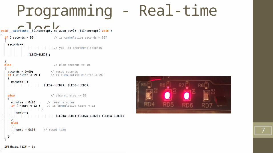
Programming - Real-time clock
7
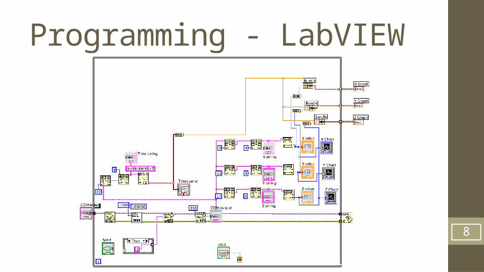
Programming - LabVIEW
8

Programming - LabVIEW
9
Progress & Plans - Faisal Accomplishments:
Code for ADC initialization of multiple channels to get Three Readings from the Accelerometer.
Send routine to perform calculations on the data points and send through RS-232. (interrupt Based)
Saving data points in the processors Data Space. Used Buttons in order to Start/Stop and Send, but decided to go with another
approach. UART RS-232 is now configured to receive/send to be able to send data upon request.
Current Progress: Currently working on the Threshold(); functionality. Get Displacement/RPM from accelerometer values.
Future Plans: Multiple operating modes. Test the overall code on the PCB. Issue a specification list for the Final Design.
10
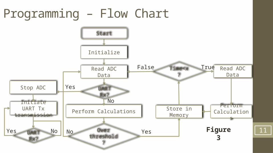
Programming – Flow Chart
11
Initialize
Read ADC Data
Perform Calculations
Over threshold?
YesNo Figure 3
Store in Memory
Time<x?
Read ADC Data
Perform Calculations
TrueFalse
UART Rx?
No
Yes
Initiate UART Tx
transmission
UART Rx?
Yes No
Start
Stop ADC
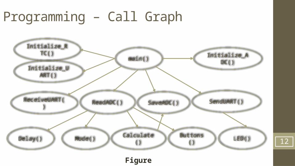
Programming – Call Graph
12
main()Initialize_ADC(
)
Initialize_RTC()
SendUART()SaveADC()ReadADC()ReceiveUART()
LED()Buttons()Calculate()Delay() Mode()
Figure 4
Initialize_UART()
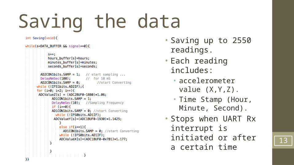
Saving the data• Saving up to 2550
readings.• Each reading
includes:• accelerometer
value (X,Y,Z).• Time Stamp (Hour,
Minute, Second).
• Stops when UART Rx interrupt is initiated or after a certain time
13
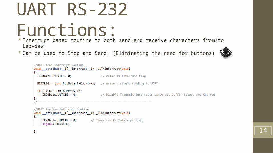
UART RS-232 Functions: Interrupt based routine to both send and receive characters from/to Labview. Can be used to Stop and Send. (Eliminating the need for buttons)
14
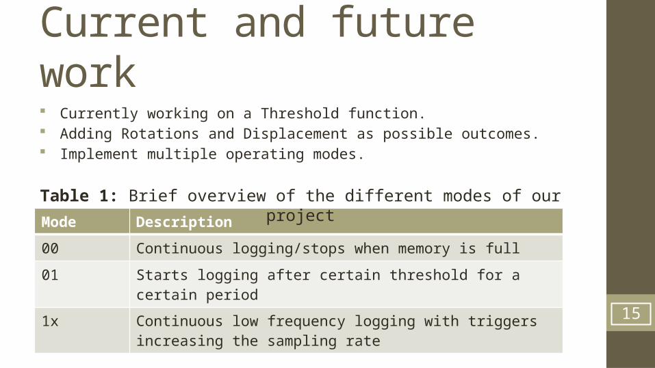
Current and future work
Mode Description
00 Continuous logging/stops when memory is full
01 Starts logging after certain threshold for a certain period
1x Continuous low frequency logging with triggers increasing the sampling rate 15
Table 1: Brief overview of the different modes of our project
Currently working on a Threshold function. Adding Rotations and Displacement as possible outcomes. Implement multiple operating modes.
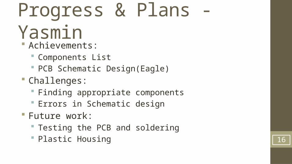
Progress & Plans - Yasmin Achievements:
Components List PCB Schematic Design(Eagle)
Challenges: Finding appropriate components Errors in Schematic design
Future work: Testing the PCB and soldering Plastic Housing 16
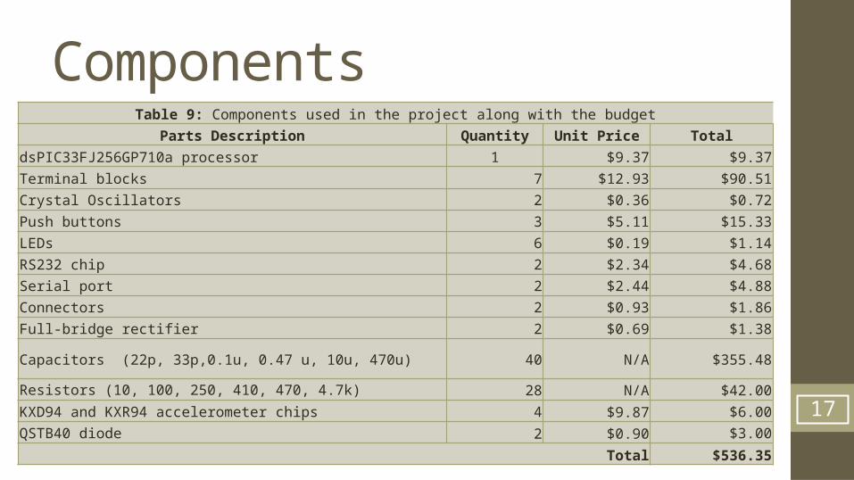
Components
17
Table 9: Components used in the project along with the budget
Parts Description Quantity Unit Price Total
dsPIC33FJ256GP710a processor 1 $9.37 $9.37
Terminal blocks 7 $12.93 $90.51
Crystal Oscillators 2 $0.36 $0.72
Push buttons 3 $5.11 $15.33
LEDs 6 $0.19 $1.14
RS232 chip 2 $2.34 $4.68
Serial port 2 $2.44 $4.88
Connectors 2 $0.93 $1.86
Full-bridge rectifier 2 $0.69 $1.38
Capacitors (22p, 33p,0.1u, 0.47 u, 10u, 470u) 40 N/A $355.48
Resistors (10, 100, 250, 410, 470, 4.7k) 28 N/A $42.00
KXD94 and KXR94 accelerometer chips 4 $9.87 $6.00
QSTB40 diode 2 $0.90 $3.00
Total $536.35
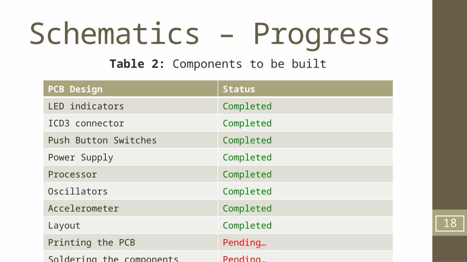
Schematics – Progress
PCB Design Status
LED indicators Completed
ICD3 connector Completed
Push Button Switches Completed
Power Supply Completed
Processor Completed
Oscillators Completed
Accelerometer Completed
Layout Completed
Printing the PCB Pending…
Soldering the components Pending…
18
Table 2: Components to be built
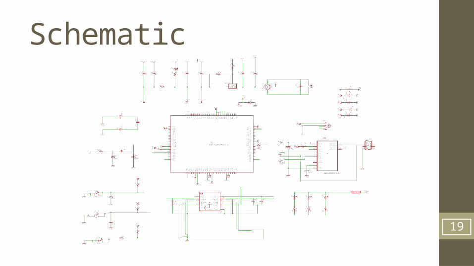
Schematic
19
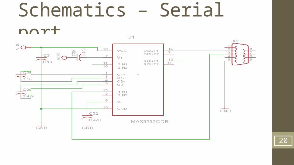
Schematics – Serial port
20
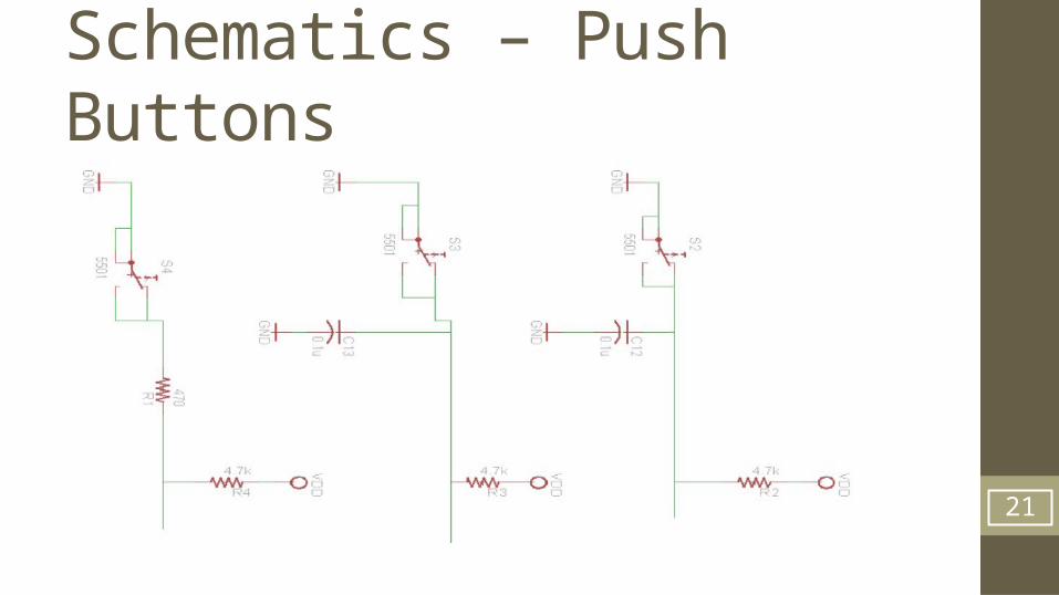
Schematics – Push Buttons
21
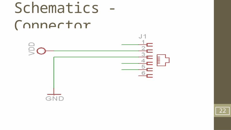
Schematics - Connector
22

Schematics – LED
23
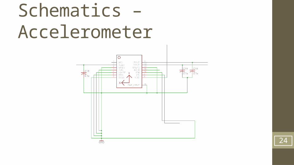
Schematics –Accelerometer
24
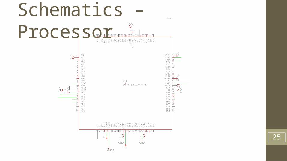
Schematics – Processor
25
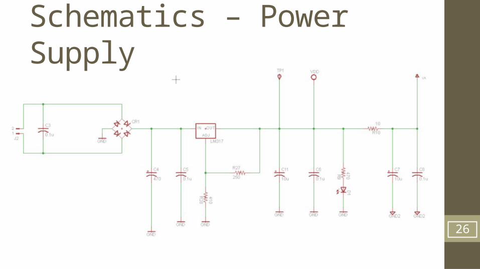
Schematics – Power Supply
26
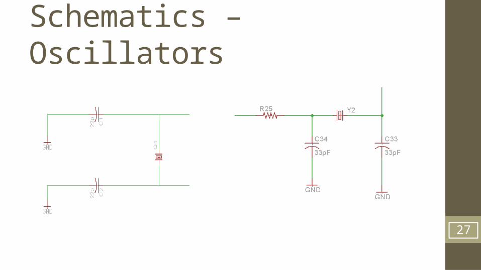
Schematics – Oscillators
27

PCB layout
28
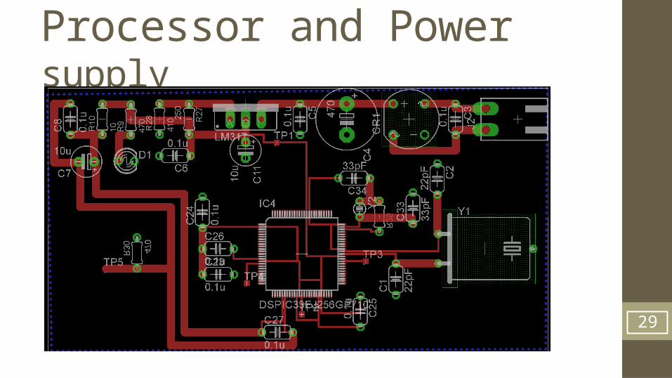
Processor and Power supply
29
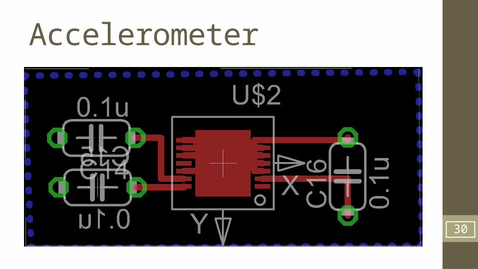
Accelerometer
30
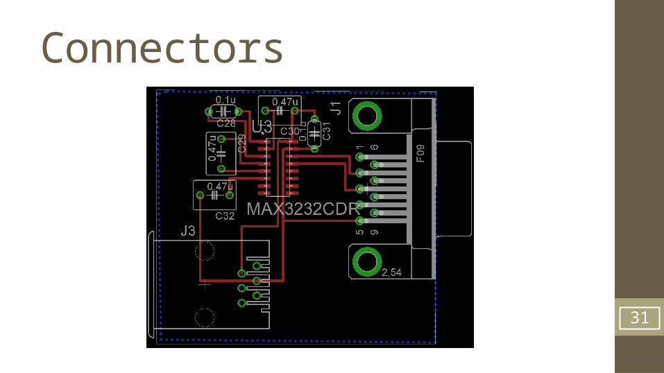
Connectors
31
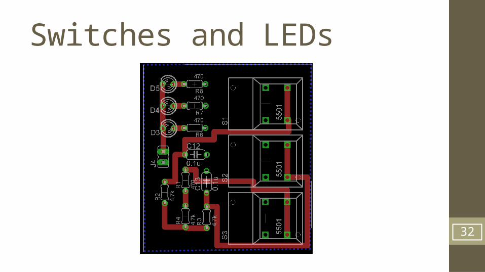
Switches and LEDs
32
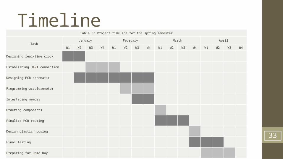
TimelineTable 3: Project timeline for the spring semester
TaskJanuary February March April
W1 W2 W3 W4 W1 W2 W3 W4 W1 W2 W3 W4 W1 W2 W3 W4
Designing real-time clock
Establishing UART connection
Designing PCB schematic
Programming accelerometer
Interfacing memory
Ordering components
Finalize PCB routing
Design plastic housing
Final testing
Preparing for Demo Day
33
Progress & Plans - Mohammed Achievements:
• Designing a new PCB that has a built in accelerometer• Creating a layout for the PCB and routing the wires
Challenges:• Searching and adding libraries that has the specific components needed for the PCB• Positioning the PCB layout parts• Routing the wires in shortest and non-overlapping paths
Current Progress: • Separating component parts into many boards.
Future work:• Add more sensors in the PCB for our data logger• Reduce the size of the PCB• Improve power efficiency by adding Buck convertor
34

Conclusion
• Logging Data
• Design PCB and program it
• Casing
35
References1. http://m.c.lnkd.licdn.com/2. http://www.logwell.com/capabilities/
36

Thank you for listening!
Any questions?
37


