34
DATA LOGGER SOFTWARE Version 2.0 QUICK START GUIDE ©2012 Sensor Switch, Inc., Wallingford, CT

DATA LOGGER SOFTWAREVersion 2.0
QUICK START GUIDE
©2012 Sensor Switch, Inc., Wallingford, CT

Data Logger Version 2.0Quick Start Guide
©2012 Sensor Switch, Inc., Wallingford, CT 2
SYSTEM REQUIREMENTS:PC Operating Windows: 2000, XP or 7Hard-Drive Requirements: 10MBData Logger to PC Interface: USB
SOFTWARE INSTALLATION1. Open Flash Drive that came with your Data Logger Case.
2. Double click DLInstall.exe.
3 Click YES if you wish to continue the install of the Data Logger Software. (Note: the installation is very fast - less than 30 seconds)
4. Click OK.
You have successfully installed the Sensor Switch Data Logger Software.
Proceed to the Data Logger QUICK START GUIDE on the following pages.
FOR PROXY SERVER USERS ONLY:
You will need to change the configuration file. This will allow you to communicate with the data logger software suite server.
1. After installation of the data logger software, go to C:/Program Files/Sensor Switch Data Logger/ to find your DL config file.
2. Open the SSIUniv1.CFG file with the Notepad.
3. Replace the last two lines of code with your proxy server settings: a) Type over “ProxyUser “with your User Name b) Type over “ProxyPwd” with your password (If you don’t need a password, do not change “ProxyPwd”)
Proceed to the Data Logger QUICK START GUIDE on the following pages.

Data Logger Version 2.0Quick Start Guide
©2012 Sensor Switch, Inc., Wallingford, CT
CHAPTER 1: GETTING STARTED
1. Double-click the DL.exe icon on your desktop (or go to the Start menu/All Programs/Sensor Switch Data Logger/).
2. Click START.
3. Click REGISTER. Fill in your registration information. (If you have used our software in the past, please use your previous username/password.
You need to register only once to use this software suite.)
(IMPORTANT NOTE: After you register, there will be a 24 to 48 hour period before you can use the software. You will receive an email confirming your registration.)
3

Data Logger Version 2.0Quick Start Guide
©2012 Sensor Switch, Inc., Wallingford, CT
CHAPTER 2: IMPORTING A DATABASE
The Data Logger Software Suite can import a database that was created using the previous version of Data Logger soft-ware. Follow the steps below to import your database to the Data Logger Software Suite.
1. Select IMPORT OLD DATABASE PROJECT.
2. Use your Username and Password to log on to the software.
3. Select BROWSE.
4. Locate the database in your files.
4

Data Logger Version 2.0Quick Start Guide
©2012 Sensor Switch, Inc., Wallingford, CT
5. Once you have selected your database, click IMPORT.
6. In the lower portion of the screen, the database name will appear as pictured in the screen shot.
7. Once the database has been imported, the screen will look similar to the screen shot. If you wish to enter another database, repeat the process. If you are finished, select CLOSE to return to the Main Menu.
5

Data Logger Version 2.0Quick Start Guide
©2012 Sensor Switch, Inc., Wallingford, CT
CHAPTER 3: DATA LOGGER TOOLS
Data Logger Tools is a utility that allows you to customize your Data Logger report. The Building Types, Area Types and Custom Electrical Utility Rate Data can be customized. Additionally, this module can be used to erase data and to set the date and time on the dataloggers.
1. To begin, selet LOGGER TOOLS.
2. Five menu options will display on the screen. Follow the directions below for each menu option.
ERASE LOGGER MEMORY and SET THE TIME & DATE of the Logger Processor
The Data Logger memory is fixed to 8,000 records. Each analysis project generages many records. It is our recommendation to erase the Data Logger memory after each successful Data Logger report has been generated to avoid running out of memory during the next analysis project.
1. Select ERASE AND SET TIME/DATE.
2. Connect your logger devices to the computer using a commercial grade USB hub. Note: maximum number of loggers that can be connected to a PC is 18.
When they have finished, click FIND DATA LOGGER.
6

Data Logger Version 2.0Quick Start Guide
©2012 Sensor Switch, Inc., Wallingford, CT
3. A list of all the data loggers connected to the computer will appear in the serial number field.
4. Select an individual data logger or select all data loggers by using the SELECT ALL button.
5. Select the task(s) to perform by selecting the check box next to ERASE DATA and/or SET DATE/TIME. After the selection is made, select PROCESS.
6. If any errors occured when setting the logger, the screen will display: “Logger Could Not Be Erased or Date/Time Could Not Be Set.” To correct the error, select the logger on the screen. After correcting the error, select CLOSE.
7

Data Logger Version 2.0Quick Start Guide
©2012 Sensor Switch, Inc., Wallingford, CT
MODIFY BUILDING TYPES
Data Logger Software Suite comes with pre-set building types built into the program (eg. high school, office, warehouse, etc.). If you would like to add more building types, follow the steps in this MODIFY BUILDING TYPES section.
1. Select MODIFY BUILDING TYPES
2. This window will appear.
3. To enter a new building type, select NEW and type in the building types in the TYPE field. Assign the new building type with a code. Be sure the code is unique to avoid duplications. The screen display should look similar to the screen image below. Repeat as needed. When finished, select SAVE.
8

Data Logger Version 2.0Quick Start Guide
©2012 Sensor Switch, Inc., Wallingford, CT
4. The new building type will appear in the USER DEFINED BUILDING TYPE list. For additional new building types, repeat the process in step #3. When complete, select CLOSE
MODIFY AREA TYPES
Data Logger Software Suite comes with pre-set area types built into the program (eg. restroom, office, classroom, etc.). If you would like to add more building types, follow the steps in this MODIFY AREA TYPES section.
1. Click on MODIFY AREA TYPES.
2. This following screen will appear.
9

Data Logger Version 2.0Quick Start Guide
©2012 Sensor Switch, Inc., Wallingford, CT
3. To enter a new Area Type, select NEW. Type in the new area type and assign it a unique code. Repeat as needed. When finished, select SAVE.
4. The new area type will appear in the USER DEFINED AREA TYPE list. For additional new user defined area types, repeat the process in step #3. When complete, select CLOSE.
CHANGING/ENTERING ELECTRIC UTILITY RATE DATA
Data Logger Software Suite comes with one pre-set utility rate built into the program. If you would like to see the savings based on a specific time of day, follow the steps in this UTILITY RATE section.
1. Click on UTILITY RATES.
10
Data Logger Version 2.0Quick Start Guide
©2012 Sensor Switch, Inc., Wallingford, CT
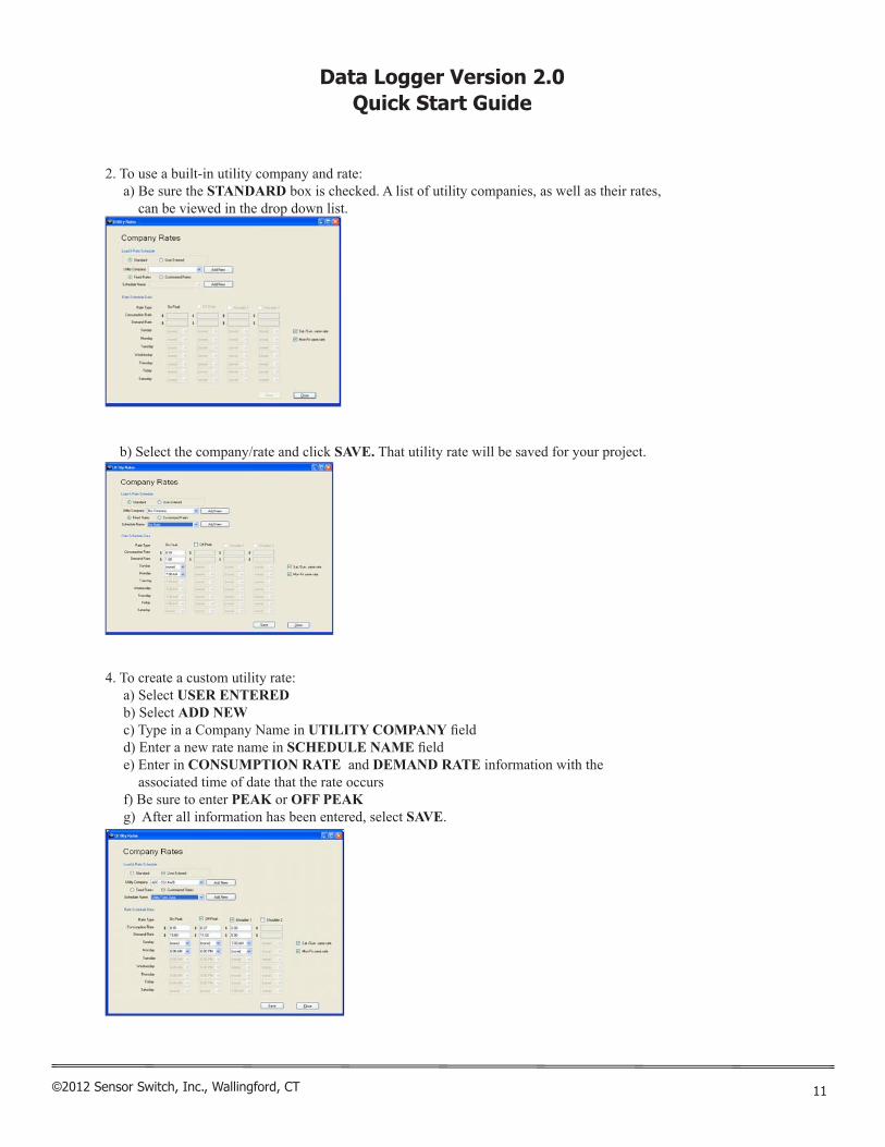
2. To use a built-in utility company and rate: a) Be sure the STANDARD box is checked. A list of utility companies, as well as their rates,
can be viewed in the drop down list.
b) Select the company/rate and click SAVE. That utility rate will be saved for your project.
4. To create a custom utility rate: a) Select USER ENTERED b) Select ADD NEW c) Type in a Company Name in UTILITY COMPANY field d) Enter a new rate name in SCHEDULE NAME field e) Enter in CONSUMPTION RATE and DEMAND RATE information with the
associated time of date that the rate occurs f) Be sure to enter PEAK or OFF PEAK g) After all information has been entered, select SAVE.
11

Data Logger Version 2.0Quick Start Guide
©2012 Sensor Switch, Inc., Wallingford, CT
5. Select CLOSE to exit.
12

Data Logger Version 2.0Quick Start Guide
©2012 Sensor Switch, Inc., Wallingford, CT
CHAPTER 4: WORKING WITH A DATABASE
This section is used to start a new project, or modify an existing project. 1. Click on USER JOB/PROJECT/DATABASES.
2. For a new project, click CREATE NEW JOB.
3. Type in new COMPANY NAME or use the pull down menu to find an existing company.
13

Data Logger Version 2.0Quick Start Guide
©2012 Sensor Switch, Inc., Wallingford, CT
4. Type in PROJECT NAME.
5. Select the INSTALL DATE and REMOVAL DATE.
6. Select BUILDING TYPE. (If you don’t find the building type you want, click on CLOSE and follow the steps in Chapter 3: MODIFY BUILDING TYPE.)
7. Select BUILDING SIZE.
14
Data Logger Version 2.0Quick Start Guide
©2012 Sensor Switch, Inc., Wallingford, CT
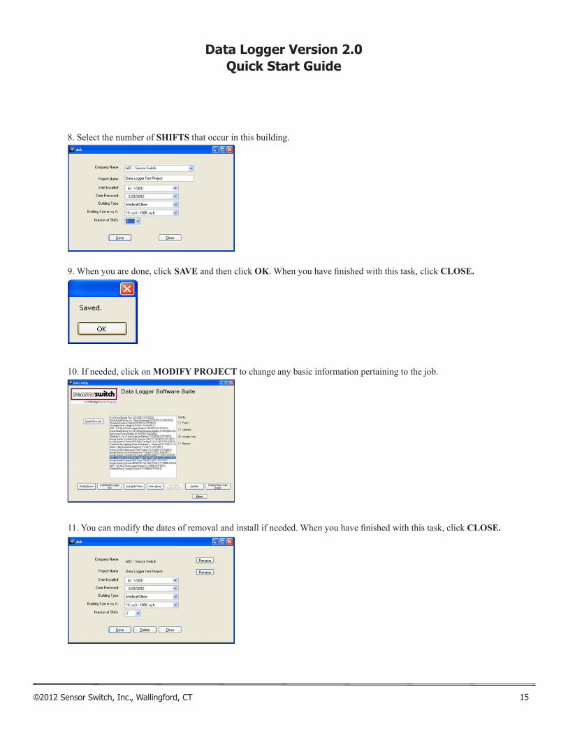
8. Select the number of SHIFTS that occur in this building.
9. When you are done, click SAVE and then click OK. When you have finished with this task, click CLOSE.
10. If needed, click on MODIFY PROJECT to change any basic information pertaining to the job.
11. You can modify the dates of removal and install if needed. When you have finished with this task, click CLOSE.
15

Data Logger Version 2.0Quick Start Guide
©2012 Sensor Switch, Inc., Wallingford, CT
12. If this is your first project, then only one project will be listed. If you have more than one project, select/highlight the project you want to work with by clicking on it. Then click ADD/MODIFY LOGGER INFO.
13. Click ADD. (This will allow the user to add a logger to the project.)
14. a) In SERIAL NUMBER type in the 8 digit numerical code found on the data logger unit. b) Fill in ROOM LOCATION and then select AREA TYPE from the pull down menu.
(If the area type you want is not present, follow the steps in Chapter 3 - MODIFY AREA TYPES.) c) Fill in EXISTING WATTAGE and RETROFIT WATTAGE. (Must be a number greater than 0.) d) Click SAVE.Note: An alternative way to make sure the logger’s serial number is correct is to click on FIND DEVICES. The program will find all loggers attached to the computer via the USB interface. Highlight the logger you want and click READ-ADD. Then fill in ROOM LOCATOR, AREA TYPE, etc. Then click SAVE.
16

Data Logger Version 2.0Quick Start Guide
©2012 Sensor Switch, Inc., Wallingford, CT
15. Logger information should show in viewing window. Repeat steps 12 - 14 for every logger in the project.
16. Click CLOSE when you have finished adding all loggers for your project.
17

Data Logger Version 2.0Quick Start Guide
©2012 Sensor Switch, Inc., Wallingford, CT
LOAD UTILITY RATE DATA
1. a) Select UTILITY COMPANY and RATE for this project. b) Click SAVE RATE. c) Click OK. d) When you have finished with this task, click CLOSE.
Note: To create a custom utility rate: a) Select USER ENTERED b) Select ADD NEW c) Type in a Company Name in UTILITY COMPANY field d) Enter a new rate name in SCHEDULE NAME field e) Enter in CONSUMPTION RATE and DEMAND RATE information with the
associated time of date that the rate occurs f) Be sure to enter PEAK or OFF PEAK g) After all information has been entered, select SAVE.
18

Data Logger Version 2.0Quick Start Guide
©2012 Sensor Switch, Inc., Wallingford, CT
MAKING GROUPS
At times analyzing the energy usage in a space requires multiple data loggers. These data loggers can be merged together to provide data for an entire room not just a specific area in a room. Select MAKING FROUPS in the menu and follow the instructions below for merging the data loggers.
1. Click on MAKE GROUPS.
2. Click ADD/NEW.
19

Data Logger Version 2.0Quick Start Guide
©2012 Sensor Switch, Inc., Wallingford, CT
3. Fill in GROUP NAME (eg. Group A), then fill in all fields on the page (eg. GROUP LOCATION, SELECT AREA TYPE, EXISTING WATTAGE, RETROFIT WATTAGE, etc.)
4. Select the logger from the AVAILABLE list and click right arrows to move the logger to GROUP’S DATA LOGGERS. Continue selecting loggers for this group. When all information is entered, click SAVE.
5. When finished making groups, click CLOSE.
20

Data Logger Version 2.0Quick Start Guide
©2012 Sensor Switch, Inc., Wallingford, CT
DOWNLOAD LOGGER MEMORY
Once the energy analysis has been completed the data from the data logger has to be transferred to the software pro-gram for analysis and report generation.
1. Select project from the list by highlighting it. Then select DOWNLOAD LOGGER MEMORY.
2. The number of loggers connected to the computer will show automatically under FOUND XX DEVICES. (If the number is “XX”, connect a logger via the USB port, wait for the computer to find the device, then click FIND DEVICES. The number should change to the number of loggers connected to the computer.)
3. In the SERIAL NUMBER pull down menu, select one of the loggers. The logger details will automatically populate (eg. room locations, area type, etc.)
21

Data Logger Version 2.0Quick Start Guide
©2012 Sensor Switch, Inc., Wallingford, CT
4. If the logger details were not previously entered, the following error message will be displayed. Select OK. The information must be manually entered. When all the data logger details have been entered click VIEW.
5. If the selected logger had memory, the viewing window will populate with the data logger memory.
6. Click SAVE. Progress bar should start and increase from left to right.
7. When all memory has been written to the database, the following message will display: YOU HAVE SUCCESS-FULLY SAVED XXXX RECORDS TO THE JOB DATABASE”.
22

Data Logger Version 2.0Quick Start Guide
©2012 Sensor Switch, Inc., Wallingford, CT
8. If the following message appears, it indicates that the logger date range is different than the project date range. Select YES if you want to use the logger date ranges or NO is you want to use the project’s date range.
9. Continue DOWNLOAD LOGGER MEMORY steps 1 - 8 for every logger in your project.
WORKING WITH A DATABASE/PROJECT/JOB
This module allows you to add or remove a logger from your project, change room location information, etc.
1. Click on USER JOB/PROJECTS/DATABASES.
2. Select a project by highlighting it, then click ADD/MODIFY LOGGER INFO.
23

Data Logger Version 2.0Quick Start Guide
©2012 Sensor Switch, Inc., Wallingford, CT
3. If you need to change any data logger details (eg. ROOM LOCATION, AREA TYPE, etc., retype over that information then click SAVE.
VALIDATING PROJECT INFORMATION FOR REPORT GENERATION
Prior to running a report to view the results of the energy analysis, all data must be reviewed to ensure all fields con-tain data. This will avoid gaps in the reporting data.
1. Select a project by highlighting it, then click VALIDATE.
2. Any errors will display in this dialogue box. To fix an error, simply click on it and the program will go to the module that needs to be modified.
24

Data Logger Version 2.0Quick Start Guide
©2012 Sensor Switch, Inc., Wallingford, CT
3. Change the information that needs modifying (for example below, the project doesn’t have a Utility rate entered for the weekends).
4. After all changes are made, click SAVE and then CLOSE.
5. Click REFRESH and the error will no longer be listed.
25
Data Logger Version 2.0Quick Start Guide
©2012 Sensor Switch, Inc., Wallingford, CT
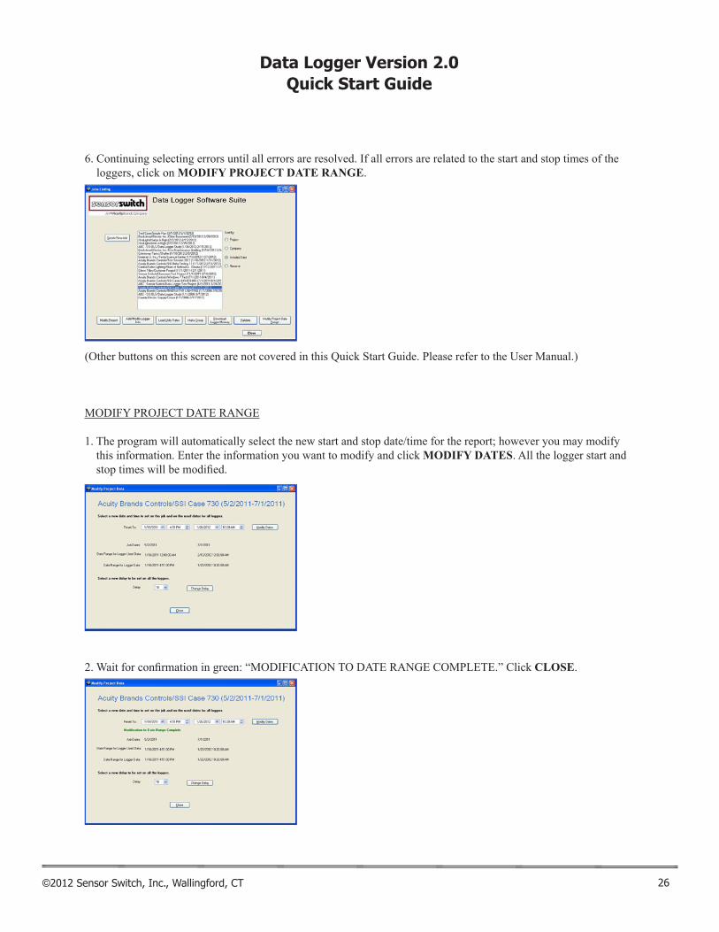
6. Continuing selecting errors until all errors are resolved. If all errors are related to the start and stop times of the loggers, click on MODIFY PROJECT DATE RANGE.
(Other buttons on this screen are not covered in this Quick Start Guide. Please refer to the User Manual.)
MODIFY PROJECT DATE RANGE
1. The program will automatically select the new start and stop date/time for the report; however you may modify this information. Enter the information you want to modify and click MODIFY DATES. All the logger start and stop times will be modified.
2. Wait for confirmation in green: “MODIFICATION TO DATE RANGE COMPLETE.” Click CLOSE.
26
Data Logger Version 2.0Quick Start Guide
©2012 Sensor Switch, Inc., Wallingford, CT
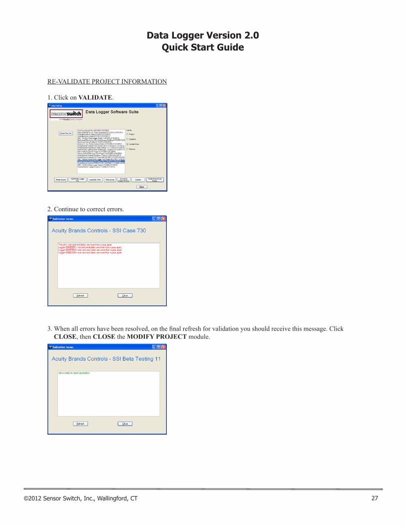
RE-VALIDATE PROJECT INFORMATION
1. Click on VALIDATE.
2. Continue to correct errors.
3. When all errors have been resolved, on the final refresh for validation you should receive this message. Click CLOSE, then CLOSE the MODIFY PROJECT module.
27

Data Logger Version 2.0Quick Start Guide
©2012 Sensor Switch, Inc., Wallingford, CT
CHAPTER 5: REPORT GENERATION
1. Click REPORT GENERATION.
2. Select a project by highlighting it.
3. Click UPLOAD.
NOTE: If any errors are still present, fix them by following the steps in Chapter 4’s VALIDATING PROJECT IN-FORMATION FOR REPORT GENERATION section above.
28

Data Logger Version 2.0Quick Start Guide
©2012 Sensor Switch, Inc., Wallingford, CT
4. Click PROCESS.
5. Process bar will indicate when process is complete.
29

Data Logger Version 2.0Quick Start Guide
©2012 Sensor Switch, Inc., Wallingford, CT
6. When the program has finished processing the date, the following message will display: “YOUR REPORT WILL BE GENERATED WITHIN THE HOUR.” Click CLOSE.
30

Data Logger Version 2.0Quick Start Guide
©2012 Sensor Switch, Inc., Wallingford, CT
RETRIEVING YOUR REPORT
1. After the hour wait time or when ready to retrieve the report, click VIEW REPORTS. Your default web browser will open. (NOTE: The report will be available for 1 year.)
2. Click on report name to download. You may select a .pdf or .xls formatted version.
3. Click CLOSE.
31

Data Logger Version 2.0Quick Start Guide
©2012 Sensor Switch, Inc., Wallingford, CT
CHAPTER 6: CONTACT INFO
1. Click CONTACT INFO.
2. When you have completed your energy analysis, return the loggers to the address on this screen. (Data logger devices are on loan for 6 weeks.)
3. If you need help on installing the data loggers, click on INSTALLATION GUIDELINES.
4. If you need additional field monitoring forms, click on FIELD MONITORING FORMS.
5. If you have lost your copy of the user manual, click on SOFTWARE MANUAL.
6. When finished, click CLOSE.
7. Click EXIT to leave the program.
32

Data Logger Version 2.0Quick Start Guide
©2012 Sensor Switch, Inc., Wallingford, CT

Data Logger Version 2.0Quick Start Guide
©2012 Sensor Switch, Inc., Wallingford, CT


