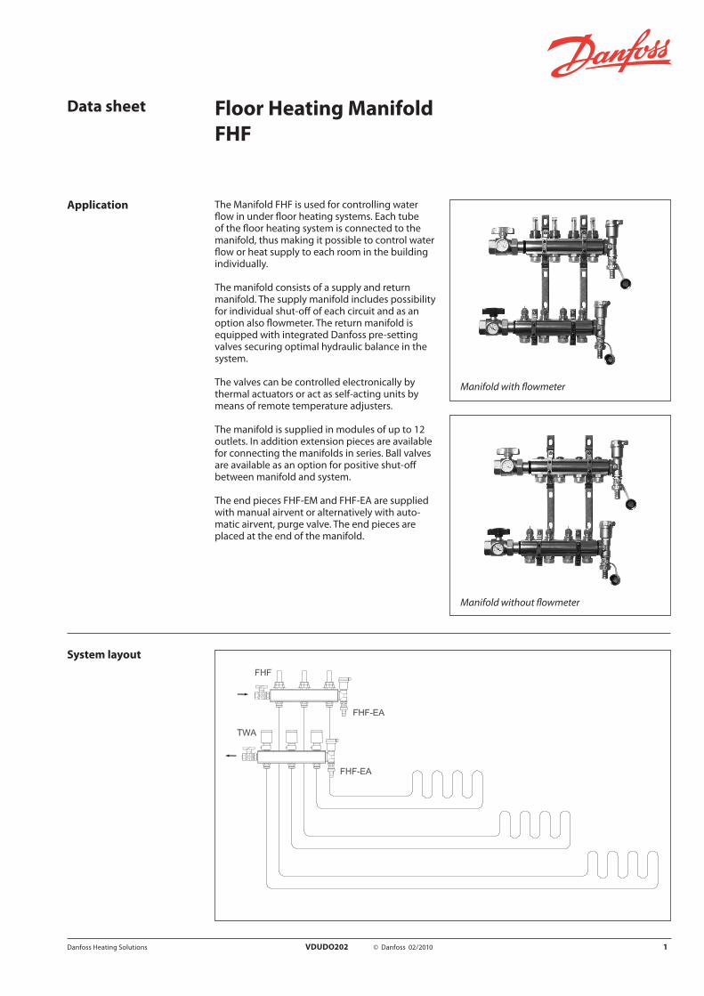
The Manifold FHF is used for controlling water flow in under floor heating systems. Each tube of the floor heating system is connected to the manifold, thus making it possible to control water flow or heat supply to each room in the building individually.
The manifold consists of a supply and return manifold. The supply manifold includes possibilityfor individual shut-off of each circuit and as an option also flowmeter. The return manifold is equipped with integrated Danfoss pre-setting valves securing optimal hydraulic balance in the system.
The valves can be controlled electronically by thermal actuators or act as self-acting units by means of remote temperature adjusters.
The manifold is supplied in modules of up to 12 outlets. In addition extension pieces are available for connecting the manifolds in series. Ball valves are available as an option for positive shut-off between manifold and system.
The end pieces FHF-EM and FHF-EA are suppliedwith manual airvent or alternatively with auto-matic airvent, purge valve. The end pieces are placed at the end of the manifold.
Application
Manifold with flowmeter
System layout
Data sheet Floor Heating ManifoldFHF
Manifold without flowmeter
Danfoss Heating Solutions VDUDO202 © Danfoss 02/2010 1
OrderingDescription Type Code no.
Manifold set 2+2 FHF-2 088U0502
Manifold set 3+3 FHF-3 088U0503
Manifold set 4+4 FHF-4 088U0504
Manifold set 5+5 FHF-5 088U0505
Manifold set 6+6 FHF-6 088U0506
Manifold set 7+7 FHF-7 088U0507
Manifold set 8+8 FHF-8 088U0508
Manifold set 9+9 FHF-9 088U0509
Manifold set 10+10 FHF-10 088U0510
Manifold set 11+11 FHF-11 088U0511
Manifold set 12+12 FHF-12 088U0512
Manifold set 2+2, with flowmeter FHF-2F 088U0522
Manifold set 3+3, with flowmeter FHF-3F 088U0523
Manifold set 4+4, with flowmeter FHF-4F 088U0524
Manifold set 5+5, with flowmeter FHF-5F 088U0525
Manifold set 6+6, with flowmeter FHF-6F 088U0526
Manifold set 7+7, with flowmeter FHF-7F 088U0527
Manifold set 8+8, with flowmeter FHF-8F 088U0528
Manifold set 9+9, with flowmeter FHF-9F 088U0529
Manifold set 10+10, with flowmeter FHF-10F 088U0530
Manifold set 11+11, with flowmeter FHF-11F 088U0531
Manifold set 12+12, with flowmeter FHF-12F 088U0532
End section - automatic airvent and purge valve FHF-EA 088U0580
End section - manual airvent and purge valve FHF-EM 088U0581
End caps -set FHF-E 088U0582
Connection pieces - set FHF-C 088U0583
Reduction bushes/pieces -set 1" - 3/4" FHF-R 088U0584
Data sheet Floor Heating Manifold, FHF
2 VDUDO202 © Danfoss 02/2010 Danfoss Heating Solutions
Description Type Code no.
Mounting brackets - set FHF-MB 088U0585
2 x ball valve 1” with tail piece - for connection to manifold and for blocking of floor heating system
FHF-BV 088U0586
1 x thermometer 0-60°C Ø35mm - for flow/re-turn temperature measurement FHD-T 088U0029
Thermal actuator, 24V, NC, Danfoss RA connection to valve TWA-A 088H3110
Thermal actuator, 230V, NC, Danfoss RA connection to valve TWA-A 088H3112
Thermal actuator, 24V, NC, with end switch, Danfoss RA connection to valve TWA-A 088H3114
Compression fittings for PEX tubing in accordance with ISO 15875.
Max working pressure: 6 barTest pressure: 10 barMax. flow temperature: 95 °CG ¾” internal thread
Max. flow temperature given by the tube manufacturer must not be exceeded.
1) Compression fittings also suitable for PERT tubing in accordance with ISO 15875.
12x2 mm 013G4152
13x2 mm 013G4153
14x2 mm 013G4154
15x2.5 mm 013G4155
16x1.5 mm 013G4157
16x2 mm 013G4156 1)
16x2.2 mm 013G4163
17x2 mm 013G4162
18x2 mm 013G4158
18x2.5 mm 013G4159
20x2 mm 013G4160
20x2.25 mm 013G4093 1)
20x2.5 mm 013G4161
Compression fittings for ALUPEX tubing.
Max working pressure: 6 barTest pressure: 10 barMax flow temperature: 95 °CG ¾” Internal thread
Max flow temperature given by the tube manufacturer must not be exceeded.
2) Compression fittings also suitable for PERT/ALU/PERT tubing.
12x2 mm 013G4182
14x2 mm 013G4184
15x2.5 mm 013G4185
16x2 mm 013G41862)
16x2.25 mm 013G4187
18x2 mm 013G4188
20x2 mm 013G4190
20x2.25 mm 013G40932)
20x2.5 mm 013G4191
Compression fittings for STEEL andCOPPER tubing
Max working pressure: 6 barTest pressure: 10 barMax flow temperature: 120 °CG ¾” Internal thread
10 mm 013G4120
12 mm 013G4122
14 mm 013G4124
15 mm 013G4125
16 mm 013G4126
18 mm 013G4128
Ordering
Data sheet Floor Heating Manifold, FHF
Danfoss Heating Solutions VDUDO202 © Danfoss 02/2010 3
Capacity/ commissioning The pre-setting of the manifold valves determines the flow in the floor heating tubes and is there-fore an important factor for obtaining optimal hy-draulic balance in the system. A correct hydraulic
Manifold without flowmeter
Pre-setting:
Room 1 NRoom 2 6
Data sheet Floor Heating Manifold, FHF
4 VDUDO202 © Danfoss 02/2010 Danfoss Heating Solutions
Manifold with flowmeter
Pre-setting:
Room 1 NRoom 2 5
Example
Room 1 1 Determine longest tube/largest room 25 m2
2 Desired cooling (ΔT) 5 °C (typical)
3 Determine heat requirement for the room 50 W/m2
4 Conversion factor 1.16
5 Calculation of flow for the room Q (l/h) = 50 W/m2 x 25 m2 5 °C x 1.16
Q (l/h) = 216 l/h
Room 2 6 Determine area for the next room 15 m2
7 Calculation of flow for the room (ΔT and heat requirement is assumed identical for the rooms in this case)
Q (l/h) = 50 W/m2 x 15 m2
5 °C x 1.16
Q (l/h) = 129 l/h
balance is important if optimal comfort shall be achieved with a minimum of energy consumption and is easily carried out following the example shown below.
The diagrams shows the capacities for each heat-ing circuit at different pre-settings of the manifold valves. Please note that the capacities are slightly different depending on whether a manifold with flowmeter or a manifold without flowmeter has been chosen. Based on the above calculations
Pre-setting themanifold valves
Design
and capacity diagrams each manifold valve is pre-set by rotating the red ring until the correct value on the ring is in-line with the sight mark on the valve.
Supply manifoldwith flowmeter
Item Description Material
1 Sightglass Heat resistant plastic
2 Flowmeter nut Brass, CuZn39Pb3
3 Flowmeter insert Brass, CuZn39Pb3
4 Supply manifold body Brass, CuZn40Pb2
5 O-ring EPDM
6 Union for compression fitting Brass, CuZn40Pb2
Supply manifoldwithout flowmeter
Item Description Material
1 Lock washer Brass, CuZn40Pb2
2 O-ring EPDM
3 Valve spindle Brass, CuZn40Pb2
4 O-ring EPDM
5 Valve tube Brass, CuZn40Pb2
6 Supply manifold body Brass, CuZn40Pb2
7 O-ring EPDM
Return manifoldwith control valve
Item Description Material
1 Gland seal -
2 Pre-setting ring PBT
3 Valve body Brass, CuZn40Pb2
4 Return manifold body Brass, CuZn40Pb2
5 Kv insert Brass, CuZn39Pb3
6 O-ring EPDM
7 Union for compression fitting Brass, CuZn40Pb2
Data sheet Floor Heating Manifold, FHF
Danfoss Heating Solutions VDUDO202 © Danfoss 02/2010 5
Max differential pressure: 0.6 barMax working pressure: Manifold without flowmeter 10 bar / Manifold with flowmeter 6 barMax test pressure: Manifold without flowmeter 16 bar / Manifold with flowmeter 10 barMax flow temperature: 90 °C
Operation conditions
Dimensions
Type 2+2 3+3 4+4 5+5 6+6 7+7 8+8 9+9 10+10 11+11 12+12
L1 (mm) 111 161 211 261 311 361 411 461 511 561 611
Data sheet Floor Heating Manifold, FHF
6 VDUDO202 © Danfoss 02/2010 Danfoss Heating Solutions
Data sheet Floor Heating Manifold, FHF
Danfoss Heating Solutions VDUDO202 © Danfoss 02/2010 7
Type 2+2 3+3 4+4 5+5 6+6 7+7 8+8 9+9 10+10 11+11 12+12
L1 (mm) 111 161 211 261 311 361 411 461 511 561 611