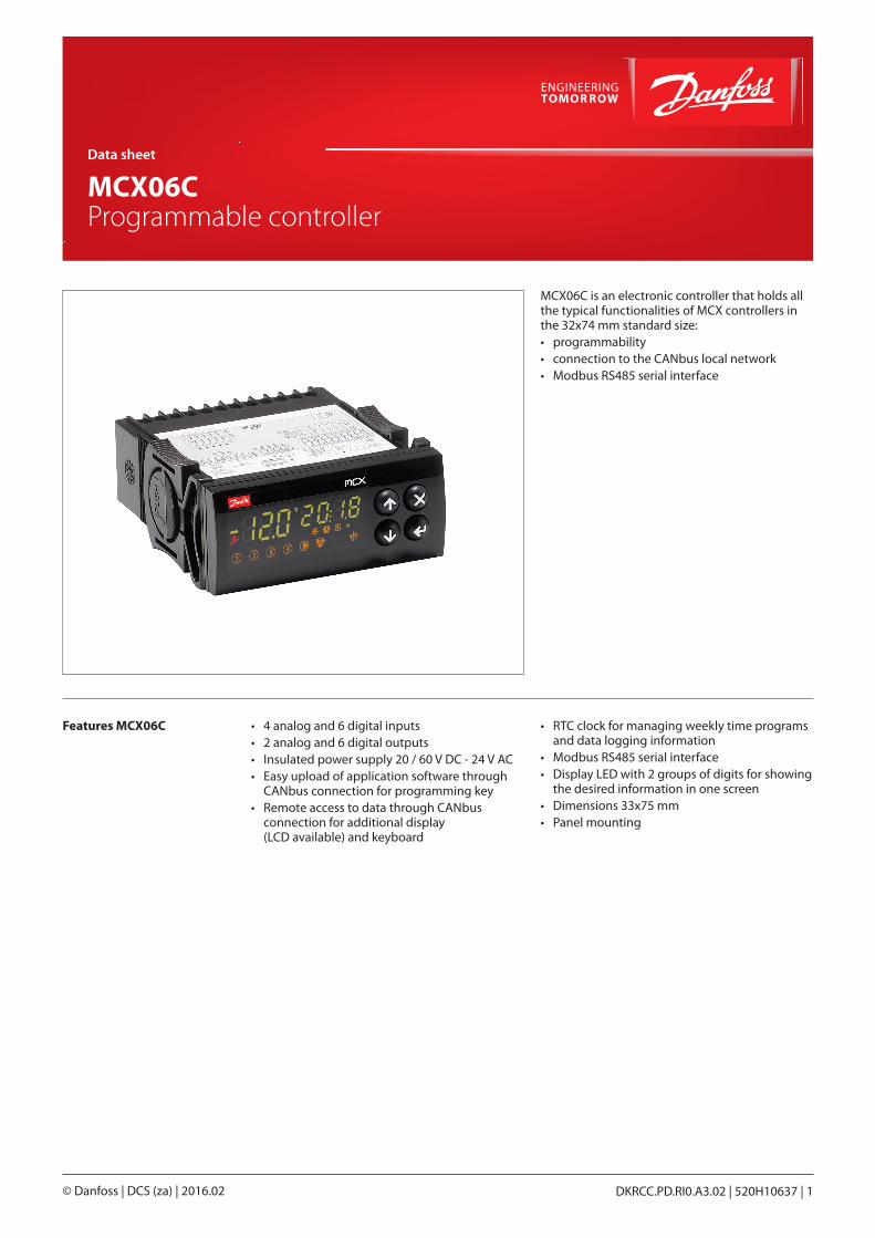
MCX06C is an electronic controller that holds all the typical functionalities of MCX controllers in the 32x74 mm standard size:• programmability• connection to the CANbus local network• Modbus RS485 serial interface
Features MCX06C • 4 analog and 6 digital inputs• 2 analog and 6 digital outputs• Insulated power supply 20 / 60 V DC - 24 V AC• Easy upload of application software through
CANbus connection for programming key• Remote access to data through CANbus
connection for additional display (LCD available) and keyboard
• RTC clock for managing weekly time programs and data logging information
• Modbus RS485 serial interface• Display LED with 2 groups of digits for showing
the desired information in one screen• Dimensions 33x75 mm• Panel mounting
Data sheet
MCX06C Programmable controller
DKRCC.PD.RI0.A3.02 | 520H10637 | 1© Danfoss | DCS (za) | 2016.02
General features FEATURES DESCRIPTION
Power supply20 / 60 V DC and 24 V AC ± 15% 50/60 Hz Maximum power consumption: 6 W, 9 VA
Insulation between power supply and the extra-low voltage: functional
Plastic housingSelf extinguishing V0 according to IEC 60695-11-10 and glowing / hot wire test at 960 °C according to IEC 60695-2-12
Ball test125 °C according to IEC 60730-1Leakage current: ≥ 250 V according to IEC 60112
Operating conditions CE: -20T60 / UL: 0T55, 90% RH non-condensing
Storage conditions -30T80, 90% RH non-condensing
Integration In Class I and / or II appliances
Index of protection IP64 ~ NEMA3R only on the front cover
Period of electric stressacross insulating parts
Long
Resistance to heat and fire Category D
Immunity against voltagesurges
Category I
Software class andstructure
Class A
Approvals
CE compliance:This product is designed to comply with the following EU standards:• Low voltage guideline: 73/23/EEC• Electromagnetic compatibility EMC: 89/336/EEC and
with the following norms: – EN61000-6-1, EN61000-6-3
(immunity for residential, commercial and light-industrial environments) – EN61000-6-2, EN61000-6-4
(immunity and emission standard for industrial environments) – EN60730
(Automatic electrical controls for household and similar use)
UL approval:• UL file E31024
Data sheet | MCX06C
© Danfoss | DCS (za) | 2016.02 DKRCC.PD.RI0.A3.02 | 520H10637 | 2
Inputs/outputs I/O TYPE NUM SPECIFICATIONS
Analoginputs
NTC0 / 1 V0 / 5 V
2 AI1, AI2Analog inputs selectable via software between:• NTC temperature probes, default: 10 kΩ at 25 °C• pressure transducers with 0/5 V output
Universal 2 AI3, AI4Universal analog inputs selectable via software between:• ON/OFF (current: 20 mA)• 0 / 1 V, 0 / 5 V, 0 / 10 V• 0 / 20 mA, 4 / 20 mA• NTC (10 kΩ at 25 °C)
• Pt100012 V+ power supply 12 V DC, 50 mA max for 4 / 20 mA transmitter (total on all outputs)5 V+ power supply 5 V DC, 80 mA max for 0 / 5 V transmitter (total on all outputs)
Digitalinput
Voltagefreecontact
6 DI1, DI2, DI3, DI4, DI5, DI6Current consumption: 5 mA
Analogoutputs
0 / 10 VPWMPPM
1 AO1Analog output selectable via software between:• pulsing output, synchronous with the line, at modulation of impulse position
(PPM) or modulation of impulse width (PWM): – open circuit voltage: 6.8 V – minimum load: 1 kΩ
• pulsing output, at modulation of impulse width (PWM) with range 100 – 500 Hz: – open circuit voltage: 6.8 V – minimum load: 1 kΩ
• 0 / 10 V DC non optoinsulated output, referred to the ground – 10 mA maximum loads
PWMPPM
1 AO2Analog output selectable via software between:• pulsing output, synchronous with the line, at modulation of impulse position
(PPM) or modulation of impulse width (PWM): – open circuit voltage: 6.8 V – minimum load: 1 kΩ
• pulsing output, at modulation of impulse width (PWM) with range 100 – 500 Hz: – open circuit voltage: 6.8 V – minimum load: 1 kΩ
Digitaloutput
Relay 6 Insulation between relays: functional (common lines internally connected)Insulation between relays and the extra-low voltage parts: reinforcedTotal current load limit: 6 AC1-NO1, C2-NO2, C3-NO3, C4-NO4, C5-NO5, C6-NO6Normally open contact relays• characteristics of each relay:
– 4 A 30 V DC / 250 V AC for resistive load - 100.000 cycles – 0.7 A 250 V AC for inductive load - 100.000 cycles with cos(phi) = 0.5 – UL: 240 V AC - 1 A resistive - 1.0 FLA - 6.0 LRA - 96 V A pilot duty 30.000 cycles
Data sheet | MCX06C
© Danfoss | DCS (za) | 2016.02 DKRCC.PD.RI0.A3.02 | 520H10637 | 3
Connection diagram
Connection
TTL Serial Comm.(if expected)
24 V AC
*
**
RS48
5 (M
odbu
s)
(if e
xpec
ted)
Ana
log
outp
ut
UN
IVER
SAL
L N
POW
ER S
UPP
LY
DIG
ITA
L O
UTP
UT
CAN
485
CAN
NTCPt1000ON/OFF0/1 V0/5 V0/10 V0/20 mA4/20 mA
UN
IVER
SAL
R1 2
0
CA
NH
CA
NL
CA
NH
CA
NLID
RX/D
-
DIR
TX/D
+
VCC
N0
1
N0
2
N0
3
N0
4
N0
5
N0
6
C 1
C 2
C 3
C 4
C 5
C 6
DI 3
DI 5
DI 1
DI 4
DI 6
DI 2
AI 4AI 2
12V+
DI 6
DI 4
DI 2
A0
2L
1
N 1
COM
COMIN
PUT/
OU
TPU
T
COM
COM
AI 3AI 1
5V+
DI 5
DI 3
DI 1
A0
1sp
eed
regu
lato
r
CA
Nbu
s
local network
L
N
L
N
to th
e A
I(8
0 m
A m
ax)
NTC
0/5
VN
TC0/
5 V
to th
e A
I(5
0 m
A m
ax)
0/10
VPW
MPP
M
PWM
PPM
5 A
5 A
5 A
5 A
5 A
5 A
Pow
er
supp
lybo
ard
CA
NG
ND
CA
NG
ND
MCX
06C
Dan
foss
80G80
33.01
*NOTE: connection has to be made on the first and last local network units, make the connection as close as possible to the connector**NOTE: C1, C2, C3, C4, C5, C6 internally connected between themselves
CONNECTORS TYPE DIMENSIONS
Input andoutputconnector
18 way Molex Microfit type (43025-1800) crimping contact type
• Molex: (43030-0001) section cable AWG20-24 (0.52-0.20 mm²)
• Molex: (43030-0004) section cable AWG26-30 (0.13-0.05 mm²)
• Instrument for the Molex crim code 69008-0982 (20-24 AWG)
• Instrument for the Molex crimp code 69008-0983 (26-30 AWG)
CANconnector
4 way Molex Wire-to-board type (87369-0400)crimping contact type
• Molex: (50212-8000) section cable AWG24-30 (0.20-0.05 mm²)
• Instrument for the Molex crimp code 63811-1200
CAN / 485connector
8 way Molex Wire-to-board type (87369-0800)crimping contact type
• Molex: (50212-8000) section cable AWG24-30 (0.20-0.05 mm²)
• Instrument for the Molex crimp code 63811-1200
Power supplyconnector
2 way Molex KK type (09-50-8021)crimping contact type
• Molex: (08-50-0105) section cable AWG18-24 (0.82-0.20 mm²)
• Molex: (08-50-0107) section cable AWG22-26 (0.32-0.13 mm²)
• Instrument for the Molex crimp code 69008-0953
Digital output1-6 connector
12 way Molex Minifit Jr. type (39-01-2125)crimping contact type
• Molex: (39-00-0077) section cable AWG16 (1.30 mm²)
• Molex: (39-00-0038) section cable AWG18-24 (0.82-0.20 mm²)
• Molex: (39-00-0046) section cable AWG22-28 (0.32-0.08 mm²)
• Instrument for the Molex crimp code 69008-0724
Data sheet | MCX06C
© Danfoss | DCS (za) | 2016.02 DKRCC.PD.RI0.A3.02 | 520H10637 | 4
Dimensions
33 28
75 71
29
75
84 13
Dan
foss
80G80
34.01
Product part numbers
User interface
Accessories part numbers
DESCRIPTION CODE NO.
MCX06C, 24V, LED, RS485, RTC, S 080G0066
MCX06C, 24V, LED, RS485, RTC, I/36 080G0107
Note: single pack codes (S) don’t include standard kit connectors, industrial pack codes (I) don’t include standard kit connectors
DESCRIPTION CODE NO.
MCX06C CONNECTORS KIT 080G0175
ACCCNX, WIRED CONNECTORS KIT FOR MCX06C, 1m CABLE 080G0081
ACCCNX, WIRED CONNECTORS KIT FOR MCX06C, 2m CABLE 080G0082
TYPE FEATURES DESCRIPTION
LEDdisplay
Display LED display with two groups of digits and 18 icons
Digits Green colour
Allarm/warning icons Red colour
Other icons Yellow / amber colour
Meaning of the icons and digits Settled by the application software
Dimensions 45x17 mm
Keyboard Number of keys 4
Keys function Set by the application software
Dan
foss
80G80
35.01
© Danfoss | DCS (za) | 2016.02 DKRCC.PD.RI0.A3.02 | 520H10637 | 5