ã Danfoss A/S, 12 - 1999 RD.5A.B2.02 1 Data sheet Pressure controls, Type KP, with enclosure IP 33 or IP 44 KP pressure controls are for use in refrigeration and air conditioning systems to give protection against excessively low suction pressure or excessively high discharge pressure. KP pressure controls are also used for starting and stopping refrigeration compressors and fans on air-cooled condensers. KP pressure controls are fitted with a single-pole double-throw (SPDT) switch. The position of the switch is determined by the pressure control setting and the pressure at the connector. KP pressure controls are available in IP 33 and IP 44 enclosures. Introduction · Ultra-short bounce times Reduces wear to a minimum and increases reliability. · Manual control Electrical contact function can be tested without the use of tools. · KP 2 with low differential for low-pressure regulation Features · KP 7 and 17 with fail-safe bellows element · Vibration and shock resistant · Compact design · Fully welded bellows element · High reliability both electronically and mechanically. Approvals CE-marked in accordance with EN 60947-4/-5 for sale in Europe. F Germanischer Lloyd, Germany m DIN 32733, Germany (KP1, KP2, KP7, KP17) P Polski Rejestr Statków, Poland DnV, Det norske Veritas, Norway RINA, Registro Italiano Navale, Italy BV, France LR, England MRS, Maritime Register of Shipping, Russia Versions with UL and CSA approvals can be supplied to special order. Materials in contact with the medium Unit type Material KP 1, 2, 5, 7, 15 Tinbronze, no. 2.1020 to DIN 17662 and 17 Free cutting steel, no. 1.0737 / 1.0718 to DIN 1651 KP 1A, 5A, 7A Stainless steel 18/8, no. 1.0737 / 1.0718 to DIN 17440 and 15A only Free cutting steel, no. 1.0719 to DIN 1651 Steel, no. 1.0330 to DIN 1624 Aluminium, no. 3.0255 to DIN 1712
Transcript
� Danfoss A/S, 12 - 1999 RD.5A.B2.02 1
Data sheet Pressure controls,Type KP, with enclosure IP 33 or IP 44
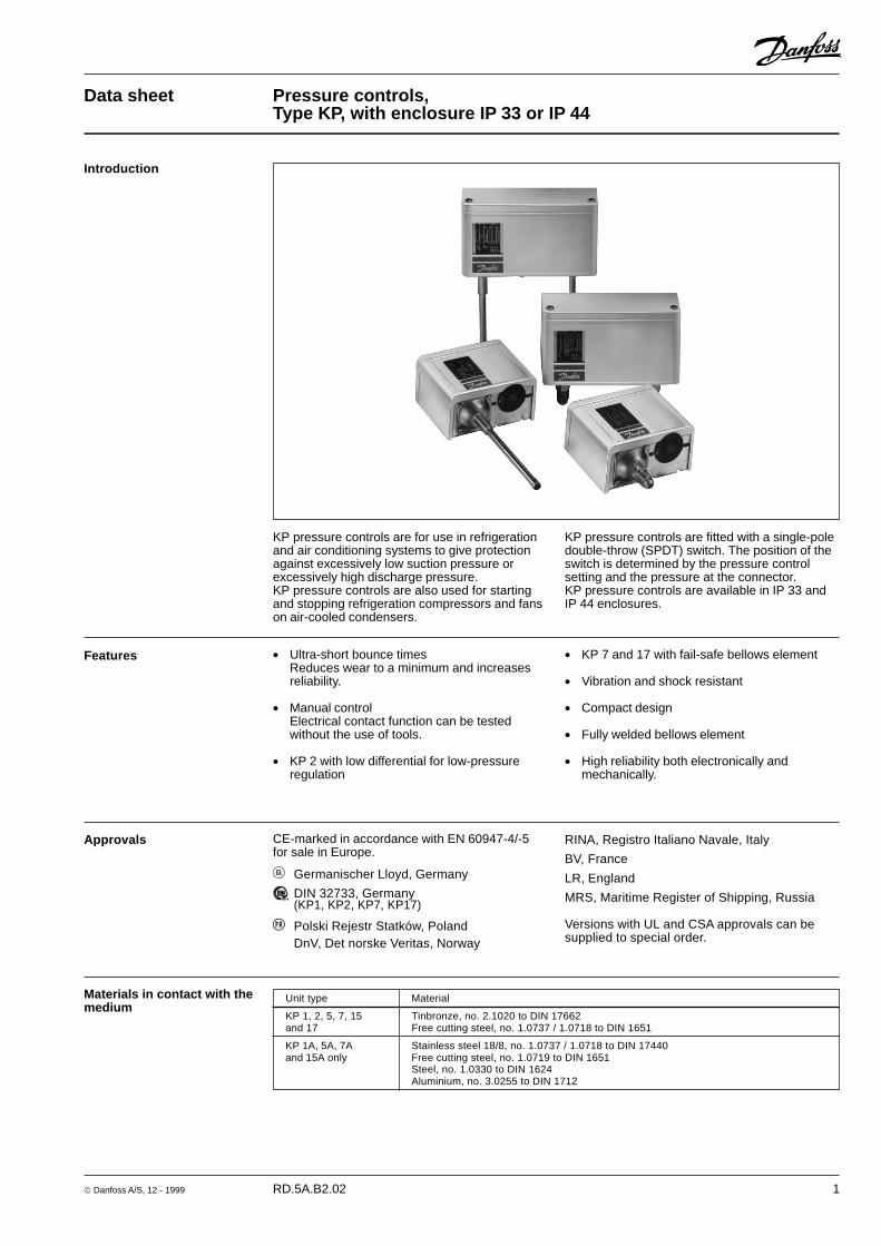
KP pressure controls are for use in refrigerationand air conditioning systems to give protectionagainst excessively low suction pressure orexcessively high discharge pressure.KP pressure controls are also used for startingand stopping refrigeration compressors and fanson air-cooled condensers.
KP pressure controls are fitted with a single-poledouble-throw (SPDT) switch. The position of theswitch is determined by the pressure controlsetting and the pressure at the connector.KP pressure controls are available in IP 33 andIP 44 enclosures.
Introduction
� Ultra-short bounce timesReduces wear to a minimum and increasesreliability.
� Manual controlElectrical contact function can be testedwithout the use of tools.
� KP 2 with low differential for low-pressureregulation
Features � KP 7 and 17 with fail-safe bellows element
� Vibration and shock resistant
� Compact design
� Fully welded bellows element
� High reliability both electronically andmechanically.
Approvals CE-marked in accordance with EN 60947-4/-5for sale in Europe.
� Germanischer Lloyd, Germany
� DIN 32733, Germany(KP1, KP2, KP7, KP17)
� Polski Rejestr Statków, PolandDnV, Det norske Veritas, Norway
RINA, Registro Italiano Navale, Italy
BV, France
LR, England
MRS, Maritime Register of Shipping, Russia
Versions with UL and CSA approvals can besupplied to special order.
Materials in contact with themedium
Unit type Material
KP 1, 2, 5, 7, 15 Tinbronze, no. 2.1020 to DIN 17662and 17 Free cutting steel, no. 1.0737 / 1.0718 to DIN 1651
KP 1A, 5A, 7A Stainless steel 18/8, no. 1.0737 / 1.0718 to DIN 17440and 15A only Free cutting steel, no. 1.0719 to DIN 1651
Steel, no. 1.0330 to DIN 1624Aluminium, no. 3.0255 to DIN 1712
2 RD.5A.B2.02 � Danfoss A/S, 12 - 1999
Data sheeet Pressure controls, type KP, with enclosure IP 33 or IP 44
Ambient temperature�40 � +65�C (+80�C for max. 2 hours).
DIN-approved units:�25 � +65�C (+80�C for max. 2 hours).
Max. working pressureLP: PB = 17 barHP: PB = 32 bar
Max. test pressureLP: p’ = 20 barHP: p’ = 35 bar
Contact loadAlternating current:AC1: 16 A, 400 VAC3: 16 A, 400 VAC15: 10 A, 400 VMax. starting current (L.R.): 112 A, 400 V
Direct current:DC13: 12 W, 220 V control current
Cable connectionThe cable entry can be used for 6 � 14 mm dia.cables.A Pg 13.5 screwed cable entry can also be usedfor 6 � 14 mm cable. With 8 � 16 mm cable astandard Pg 16 screwed cable entry can beused.
EnclosureIP 33 to EN 60529 / IEC 529Enclosure IP 33 is obtained when the unitswithout top cover are mounted on a flat surfaceor bracket. The bracket must be fixed to the unitso that all unused holes are covered.
IP 44 to EN 60529 / IEC 529Enclosure IP 44 is obtained when the unitswith top cover are mounted on a flat surface orbracket. The bracket must be fixed to the unit sothat all unused holes are covered.
KP pressure controls with auto reset aresupplied with top cover. For KP pressurecontrols with manual reset, the top cover mustbe separately ordered.
IP 55 to EN 60529 / IEC 529IP 55 is obtained when the KP pressure controlsare mounted in an IP 55 enclosure, (code no.060-0330 for single pressure controls and codeno. 060-0350 for dual pressure controls).IP 55 enclosure has to be ordered separately.
Technical data Contact systems
Low pressure (LP)
High pressure (HP)
Dual pressure(HP/HP)
Dual pressure(LP/HP)
Dual pressure(LP/HP)
� Danfoss A/S, 12 - 1999 RD.5A.B2.02 3
Data sheeet Pressure controls, type KP, with enclosure IP 33 or IP 44
Low pressure (LP) High pressure (HP) Reset Code no.
Regulatingrange
bar
Differential�pbar
Regulatingrange
bar
Differential�pbar
Lowpressure
LP
Highpressure
HP
Contactsystem
1/4 in.6 mmflare
1/4 in.ODF
solder
6 mmODF
solder
Pressure Type
For fluorinated refrigerants
Ordering
1) Pressure controls with gold-plated contacts2) Conv.: optional automatic or manual reset3) Enclosure IP 334) Enclosure IP 44
Accessories for KP pressure controls with M10 � 0.75 connections:Weld connections: M10 � 0.75 nut and �6 � 150 mm seamless steel pipe, code no. 060-0057Steel cap. tube: 1 m with 2 � M10 � 0.75 nuts, code no. 060-0078Steel cap. tube: 1 m with 1 � M10 � 0.75 and G 3/8 nut, code no. 060-0082Adaptor: M 10 � 0.75 1/4 to 1/8 NPT int. thread, code no. 060-0141IP 55 enclosure for single pressure controls, code no. 060-0330IP 55 enclosure for dual pressure controls, code no. 060-0350
For other accessories: see "Spare parts and accessories", RK.0X.G2.02.
1) Meets the requirements in VBG 20 dealing with safety equipment and excess pressures.2) W = Wächter (pressostat), B = Begrenzer (pressure control with ext. reset), S = Sicherheitsdruckbegrenzer (pressure control with int. reset).
A bellows rupture in inner bellows will cause the refrigeration plant compressor to stop.A rupture of the outer bellows will cause the stop pressure to fall approx. 3 bar under the set value.
3) Enclosure IP 33.4) Enclosure IP 44.
� Danfoss A/S, 12 - 1999 RD.5A.B2.02 5
Data sheeet Pressure controls, type KP, with enclosure IP 33 or IP 44
Design
The switch in the KP has a snap-action functionand the bellows moves only when the cut-in orcut-out value is reached.
The bellows becomes connected to the lowor high pressure side of the plant throughconnection (10) or (11).
The design of the KP affords the followingadvantages:� high contact load� ultra-short bounce time� high resistance to pulsation� vibration resistance up to 4 g in the range
0-1000 Hz� long mechanical and electrical life
1. Low pressure (LP) setting spindle2. Differential setting spindle, LP3. Main arm5. High pressure (HP) setting spindle
Data sheeet Pressure controls, type KP, with enclosure IP 33 or IP 44
Design(continued)
KP 1, KP 2, KP 7 and KP 17 units with designa-tion W, B or S have been tested and approvedby � (Technischer Über-wachungs Verein,Federal Republic ofGermany) in accordance with DIN 32733.W = Wächter (pressure control)B = Begrenzer
(pressure control with external reset)S = Sicherheitsdruckbegrenzer
(pressure control with internal reset).
KP 7 and KP 17 have a double bellows: an outerbellows and a regulating bellows. When systempressure exceeds the set value, the KP willautomatically stop the plant. The double bellowssystem prevents loss of charge in the event ofbellows rupture.
A rupture in the outer bellows will cause thecontrol cut-out pressure to fall to about 3 barunder the set value, thus providing a fail-safefunction.
Versions with designation W or AW cut in againautomatically when the pressure has fallen tothe set value minus the differential.Versions with designation B or AB can be cut inmanually with the external reset button whenthe pressure in KP 1 has raised 0.7 bar aboveset value and in KP 7 has fallen 4 bar under theset value.
Versions with designation S or AS can be cut inmanually with the internal reset arm when thepressure has fallen 4 bar under the set value.
All KP pressure controls, including those whichare DIN-approved, operate independently ofchanges in the ambient temperature aroundthe control housing. Therefore the set cut-outpressure and differential are held constantprovided the permissible ambient temperaturesare not exceeded.
Data sheeet Pressure controls, type KP, with enclosure IP 33 or IP 44
Terminology Reset1. Manual reset:
Units with manual reset can only be resetduring operation by activation of the resetbutton.
2. Automatic reset:After operational stop, these units resetautomatically.
3. Convertible reset:Units with optional reset can be activated byautomatic and/or manual reset.
Permissible working pressureThe permissible working pressure is determinedby the pressure that can be safely allowed in therefrigerating system or any of the units within it.The permissible working pressure is designatedPB (Der zulässige Betriebsüberdruck).
Test pressureThe test pressure is the pressure used instrength tests and/or leakage tests onrefrigerating systems or individual parts insystems. The test pressure is designated p’.
"Snap function"A certain contact force is maintained untilirrevocable "snap" is initiated. The time duringwhich the contact force approaches zero is thuslimited to a very few milliseconds. Thereforecontact bounce cannot occur as a result of, forexample, slight vibrations, before the cut-outpoint. Contact systems with "Snap function" willchange over even when micro-welds arecreated between the contacts during cut-in. Avery high force is created during cut-out toseparate the contacts. This force immediatelyshears off all the welds. Thus the cut-out pointof the unit remains very accurate andcompletely independent of themagnitude of the current load.
Setting Pressure controls with automatic reset - HP:Set the HP pressure on the "CUT-OUT" scale.One rotation of the HP spindle � 2.3 bar.Set the HP differential on the "DIFF" scale.One rotation of the differential spindle � 0.3 bar.The HP start pressure is the HP stop pressureminus the differential.Start and stop pressures for both the LP and HPsides of the system should always be checkedwith an accurate pressure gauge.
Pressure controls with manual resetSet the stop pressure on "CUT-OUT" scale(range scale).Low pressure controls can be manually resetwhen the pressure is equal to the stop pressureplus the differential.High pressure controls can be manually resetwhen the pressure is equal to the stop pressureminus the differential.
Pressure controls with automatic reset - LP:Set the LP start pressure on the "CUT-IN" scale(range scale).One rotation of the low pressure spindle �0.7 bar.Set the LP differential on the "DIFF" scale. Onerotation of the differential spindle � 0.15 bar.The LP stop pressure is the LP start pressureminus the differential.
Note:The LP stop pressure must be aboveabsolute vacuum (pe = �1 bar)!
If with low stop pressure the refrigerationcompressor will not stop, check to ensure thatthe differential value has not been set too high!
8 RD.5A.B2.02 � Danfoss A/S, 12 - 1999
Data sheeet Pressure controls, type KP, with enclosure IP 33 or IP 44
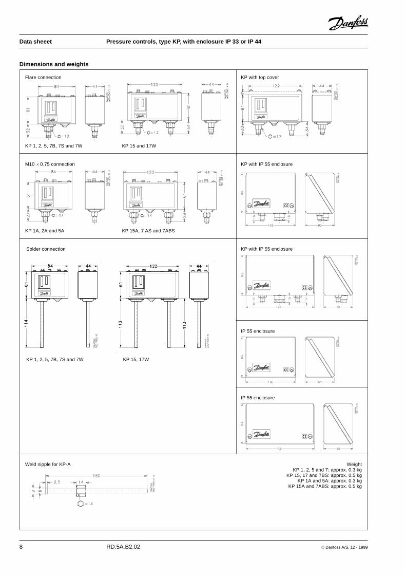
Dimensions and weights
Flare connection
KP 1, 2, 5, 7B, 7S and 7W KP 15 and 17W
M10 � 0.75 connection
KP 1A, 2A and 5A KP 15A, 7 AS and 7ABS
Solder connection
KP 1, 2, 5, 7B, 7S and 7W KP 15, 17W
IP 55 enclosure
KP with top cover
KP with IP 55 enclosure
KP with IP 55 enclosure
IP 55 enclosure
Weld nipple for KP-A WeightKP 1, 2, 5 and 7: approx. 0.3 kg
KP 15, 17 and 7BS: approx. 0.5 kgKP 1A and 5A: approx. 0.3 kg
KP 15A and 7ABS: approx. 0.5 kg
� Danfoss A/S, 12 - 1999 RD.5A.B2.02 9
Data sheeet Pressure controls, type KP, with enclosure IP 33 or IP 44
10 RD.5A.B2.02 � Danfoss A/S, 12 - 1999
Data sheeet Pressure controls, type KP, with enclosure IP 33 or IP 44
� Danfoss A/S, 12 - 1999 RD.5A.B2.02 11
Data sheeet Pressure controls, type KP, with enclosure IP 33 or IP 44
12 RD.5A.B2.02 � Danfoss A/S, 12 - 1999
Data sheeet Pressure controls, type KP, with enclosure IP 33 or IP 44


![Pressure switch and Thermostat. Type KP and KPI€¦ · Pressure switch, types KP 35, KP 36, KPI 35, KPI 36 and KPI 38 Standard IP30 housing Net weight approx. 0.3 kg Dimensions [mm]](https://static.documents.pub/doc/80x56/5e1807b88e0d6e57566d1c8a/pressure-switch-and-thermostat-type-kp-and-kpi-pressure-switch-types-kp-35-kp.jpg)


