Data sheet Pressure switch and thermostat, types KP and KPI
IC.PD.P10.F4.02 / 520B6484
Type
Setting range pe Differential
Reset
Pressure connection
Max. test pressure Contact
material Code no.
[bar] [bar] [bar] [bar]
KP 34 0.1 – 1.0 0.1 – 0.4 Automatic G 1/2 A 4.0 silver 060-216466
0.1 – 1.0 0.2 Manual G 1/2 A 4.0 silver 060-216366
KP 350.4 – 3.4 0.4 – 2.2 Automatic G 1/2 A 10 silver 060-216666
0.4 – 3.4 0.5 Manual G 1/2 A 10 silver 060-216566
KP 36 1.0 – 10.0 0.7 – 4.0 Automatic G 1/2 A 17 silver 060-215966
1.0 – 10.0 0.7 Manual G 1/2 A 17 silver 060-216066
KP 374.0 – 20.0 1.8 – 3.1 Automatic G 1/2 A 28 silver 060-216166
4.0 – 20.0 3.0 Manual G 1/2 A 28 silver 060-216266
Pressure switch, types KP 34 – KP 37, boiler version
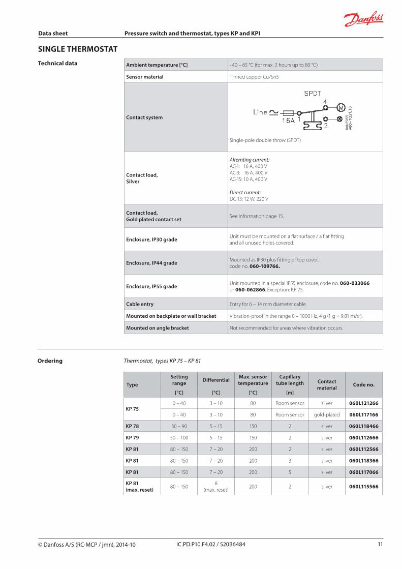
Contact systemand application
Switch type – single pole double throw Switch action Application
1. Terminal 1 – 4 close high and open low Terminal 1 – 2 can be used as low pressure alarm
1. Low pressure cut-out
2. Terminal 1 – 2 open high and close low Terminal 1 – 4 can be used as high pressure alarm
2. High pressure cut-out
SPDT
Setting
Cut-in and cut-out pressures of the system should always be checked with an accurate pressure gauge.
Pressure setting for switches with automatic reset.1. Set the cut-in pressure on the “CUT-IN”
scale (range scale),2. Set the differential on the “DIFF” scale.
The cut-out pressure must be above absolutevacuum (pe = -1 bar.).For high pressure switches the restart pressure is equal to cut-out pressure minus differential.
Pressure switches with manual resetSet the cut-out presure on the “CUT-OUT” scale (range scale).Low pressure limiters can be manually reset when the pressure is equal to the cut-out pressure plus the differential. High pressure limiters can be manually reset when the pressure is equal to the stop pressure minus the differential.Note:
For low pressure switches the restart pressure is equal to cut-out pressure plus differential value.
Data sheet Pressure switch and thermostat, types KP and KPI
5 IC.PD.P10.F4.02 / 520B6484
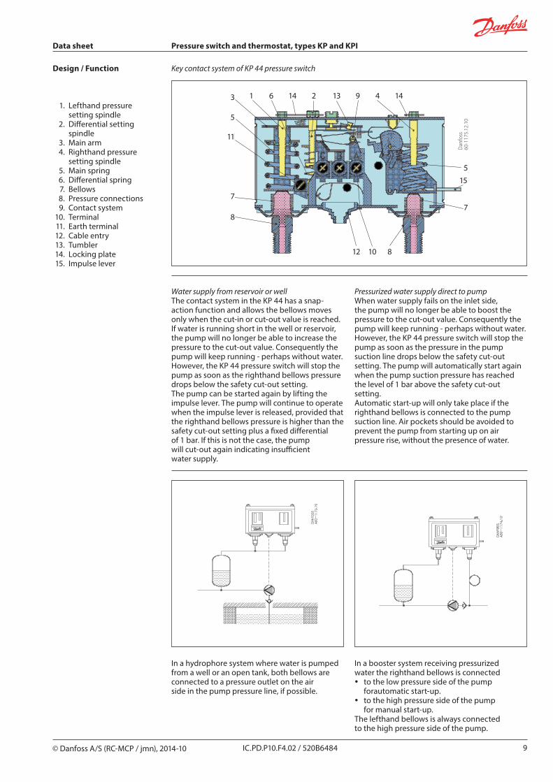
Design / Function
1. Setting spindle 2. Differential setting
spindle 3. Main arm 4. Main spring 5. Differential spring 6. Bellows 7. Pressure connector 8. Contact system 9. Connection terminals 10. Earth terminal 11. Cable entry 12. Omega spring (KPI) 12. Tumbler (KP) 13. Locking screw 14. Manual reset
The contact system in KP pressure switches has a snap function. This means that the bellows is active only when the cut-in or cut out value is reached. The bellows is connected to the pressure of the controlled plant via the connector (7)
Danfoss KPI pressure switches are designed so that the bellows moves in the same proportion as the pressure switches change. To ensure a snap function on contact change over, an omega spring is located between bellows and contact system.
Data sheet Pressure switch and thermostat, types KP and KPI
IC.PD.P10.F4.02 / 520B6484
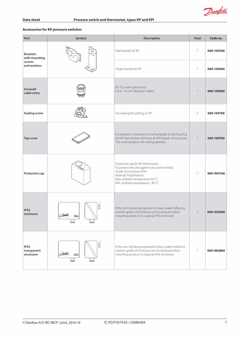
Accessories for KP pressure switches
Part Symbol Description Total Code no.
Brackets with mounting screws and washers
Wall bracket for KP 1 060-105566
Angle bracket for KP 1 060-105666
Screwed cable entry
PG 13.5 with special nutFor 6 –14 mm diameter cables 1 060-105966
Sealing screw For sealing the setting on KP 2 060-105766
Top coverIf a bracket is mounted on the backplate of the housing, the KP thermostats will have an IP44 grade of enclosure. The cover protects the setting spindles.
1 060-109766
Protective cap
Protective cap for KP thermostats.To protect the unit against rain and humidity.Grade of enclosure: IP44Material: PolyethyleneMax. ambient temperature: 65 °CMin. ambient temperature: -40 °C
1 060-003166
IP55enclosure
If the unit risk being exposed to heavy water influence a better grade of enclosure can be achieved when mounting product in a special IP55 enclosure.
1 060-033066
IP55transparentenclosure
If the unit risk being exposed to heavy water influence a better grade of enclosure can be achieved when mounting product in a special IP55 enclosure.
Data sheet Pressure switch and thermostat, types KP and KPI
IC.PD.P10.F4.02 / 520B6484
Water supply from reservoir or well The contact system in the KP 44 has a snap-action function and allows the bellows moves only when the cut-in or cut-out value is reached.If water is running short in the well or reservoir, the pump will no longer be able to increase the pressure to the cut-out value. Consequently the pump will keep running - perhaps without water. However, the KP 44 pressure switch will stop the pump as soon as the righthand bellows pressure drops below the safety cut-out setting. The pump can be started again by lifting the impulse lever. The pump will continue to operate when the impulse lever is released, provided that the righthand bellows pressure is higher than the safety cut-out setting plus a fixed differential of 1 bar. If this is not the case, the pump will cut-out again indicating insufficient water supply.
Pressurized water supply direct to pumpWhen water supply fails on the inlet side, the pump will no longer be able to boost the pressure to the cut-out value. Consequently the pump will keep running - perhaps without water. However, the KP 44 pressure switch will stop the pump as soon as the pressure in the pump suction line drops below the safety cut-out setting. The pump will automatically start again when the pump suction pressure has reached the level of 1 bar above the safety cut-out setting.Automatic start-up will only take place if the righthand bellows is connected to the pump suction line. Air pockets should be avoided to prevent the pump from starting up on air pressure rise, without the presence of water.
In a hydrophore system where water is pumped from a well or an open tank, both bellows are connected to a pressure outlet on the air side in the pump pressure line, if possible.
In a booster system receiving pressurized water the righthand bellows is connected
y to the low pressure side of the pump forautomatic start-up.
y to the high pressure side of the pump for manual start-up.
The lefthand bellows is always connected to the high pressure side of the pump.
Required tap water pressure ≥2.3 bar ≥4.0 bar ≥5.0 bar ≥8.0 bar
Control pressure cut-out setting 3.0 bar 5.0 bar 8.0 bar 12 bar
Differential 0.7 bar 1.0 bar 3.0 bar 4.0 bar
Control pressure cut-in setting 2.3 bar 4.0 bar 5.0 bar 8.0 bar
Max. safety cut-out setting 0.8 bar 2.5 bar 3.5 bar 6.01) bar
1) 6.0 bar is the normal max. setpoint
Dan
foss
60-1
178.
12
Data sheet Pressure switch and thermostat, types KP and KPI
10 IC.PD.P10.F4.02 / 520B6484
Safety cut-out settingThe righthand bellows will automatically cut-out the pump at the safety cut-out setpoint. Automatic start-up, if any, will take place when the pressure has reached the level of 1 bar above the setpoint. Manual cut-in is made by lifting the impulse lever and releasing it again when the pressure has increased by min. 1 bar.
The safety cut-out setpoint is normally determined by the static pressure (the water column). However, in order to avoid disturbing signal interaction, care should be taken to ensure that the safety cut-out setting is at least 1.5 bar lower than the control pressure cut-in setting. See table with pressure setting examples below.
Control pressure settingsControl pressure cut-out setpoint is set on the lefthand pressure setting scale.
The differential is set between 0.7 and 4 bar.The control pressure cut-in setting will be the cut-out control pressure less the differential.
Setting
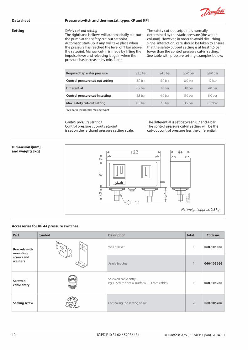
Dimensions[mm] and weights [kg]
Net weight approx. 0.5 kg
Accessories for KP 44 pressure switches
Part Symbol Description Total Code no.
Brackets with mountingscrews and washers
Wall bracket 1 060-105566
Angle bracket 1 060-105666
Screwed cable entry
Screwed cable entryPg 13.5 with special nutfor 6 – 14 mm cables 1 060-105966
Sealing screw For sealing the setting on KP 2 060-105766
Data sheet Pressure switch and thermostat, types KP and KPI
12 IC.PD.P10.F4.02 / 520B6484
The contact system in KP thermostats has a snap function. This means that the bellows is active only when the cut-in or cut-out value is reached.
Absorption chargeThe charge consists partly of a superheated gas and partly of a solid substance with a large absorption surface.The solid substance is concentrated in the sensor (7), and consequently it is always the sensor that comprises the temperature-regulating part of the thermostatic element.The sensor can be placed both warmer or colder than the thermostat housing and capillary tube. However, placing it in an ambient temperature higher or lower than 20 °C can affect the accuracy of the scale.
3. Main arm 4. Main spring 5. Differential spring 6. Bellows 7. Sensor 8. Contact system 9. Connection terminals 10. Earth terminal 11. Cable entry 12. Tumbler
6. Bellows 7. Sensor 13. Capillary tube
Thermostats with automatic resetSet the upper limit temperature on the range scale. Then set the differential on the DIFF scale.The temperature set on the range scale is also the temperature at which contact changeover re-occurs on rising temperature.The contacts changeover when the temperature has fallen to a value lower than that set on the DIFF scale.If at lower settings the plant will not start/stop, the reason might be that the differential has been set too high.
Thermostats with minimum resetSet the temperature on the range scale. The differential setting is fixed. Min. reset units will restart after the temperature at the thermostat sensor has risen by a value greater than that of the fixed differential.
Thermostats with maximum resetSet the stop temperature on the range scale. The differential setting is fixed. Max. reset units will restart after the temperature at the thermostat sensor has fallen by a value greater than that of the fixed differential
Data sheet Pressure switch and thermostat, types KP and KPI
14 IC.PD.P10.F4.02 / 520B6484
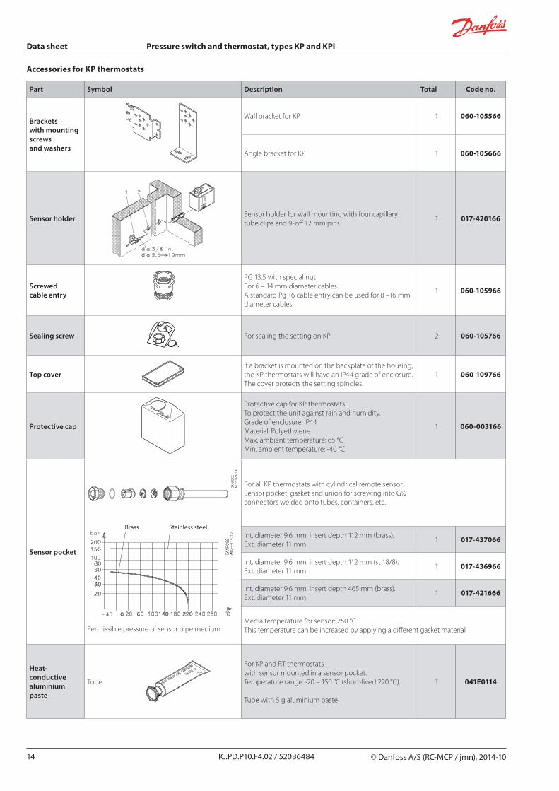
Accessories for KP thermostats
Part Symbol Description Total Code no.
Brackets with mounting screws and washers
Wall bracket for KP 1 060-105566
Angle bracket for KP 1 060-105666
Sensor holder Sensor holder for wall mounting with four capillary tube clips and 9-off 12 mm pins
1 017-420166
Screwed cable entry
PG 13.5 with special nutFor 6 – 14 mm diameter cablesA standard Pg 16 cable entry can be used for 8 –16 mm diameter cables
1 060-105966
Sealing screw For sealing the setting on KP 2 060-105766
Top coverIf a bracket is mounted on the backplate of the housing, the KP thermostats will have an IP44 grade of enclosure. The cover protects the setting spindles.
1 060-109766
Protective cap
Protective cap for KP thermostats.To protect the unit against rain and humidity.Grade of enclosure: IP44Material: PolyethyleneMax. ambient temperature: 65 °CMin. ambient temperature: -40 °C
1 060-003166
Sensor pocket
Permissible pressure of sensor pipe medium
For all KP thermostats with cylindrical remote sensor. Sensor pocket, gasket and union for screwing into G½ connectors welded onto tubes, containers, etc.
Int. diameter 9.6 mm, insert depth 112 mm (brass). Ext. diameter 11 mm
1 017-437066
Int. diameter 9.6 mm, insert depth 112 mm (st 18/8). Ext. diameter 11 mm
1 017-436966
Int. diameter 9.6 mm, insert depth 465 mm (brass). Ext. diameter 11 mm
1 017-421666
Media temperature for sensor: 250 °CThis temperature can be increased by applying a different gasket material
Heat-conductive aluminium paste
Tube
For KP and RT thermostats with sensor mounted in a sensor pocket. Temperature range: -20 – 150 °C (short-lived 220 °C)
Data sheet Pressure switch and thermostat, types KP and KPI
16 IC.PD.P10.F4.02 / 520B6484
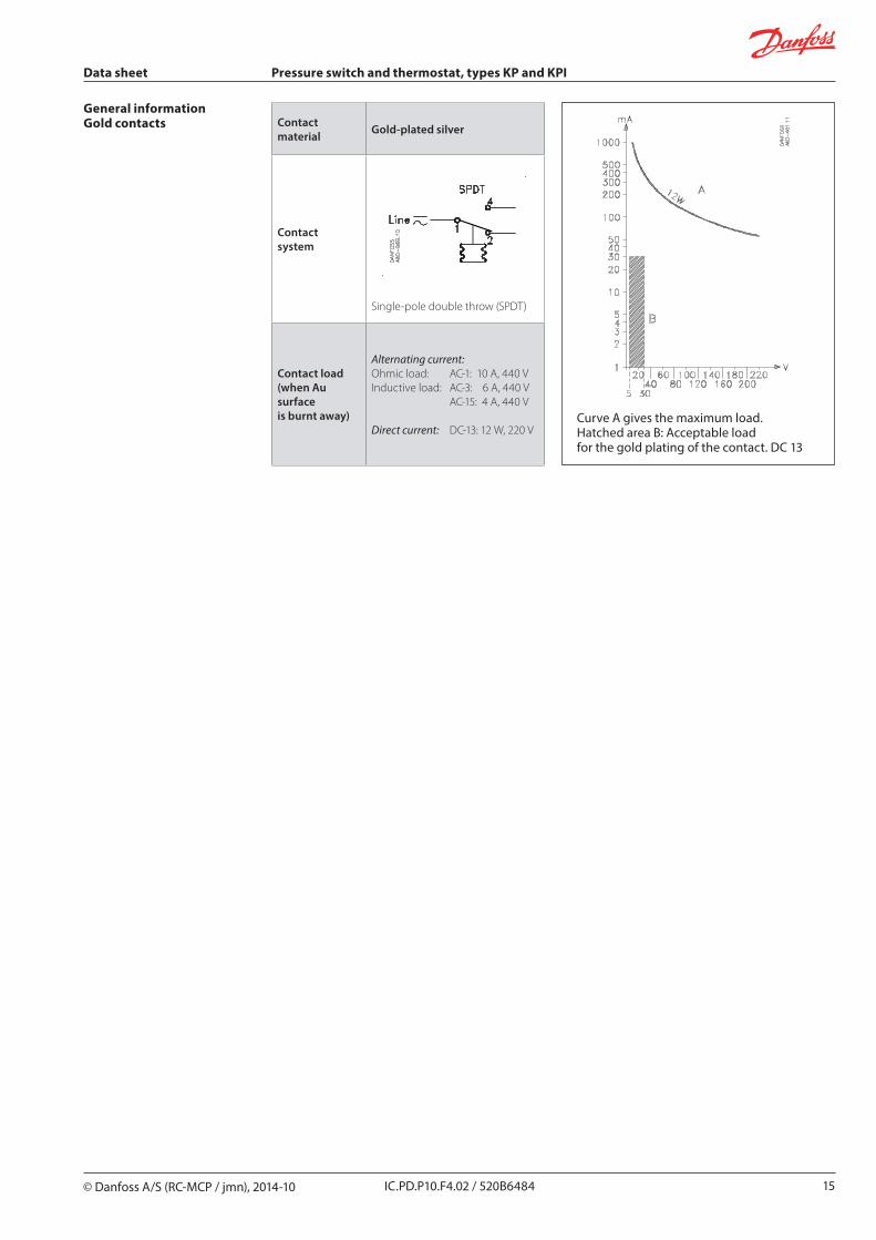
Snap functionA specific contact force is maintained until snap is initiated. The time over which contact force reaches zero is a few milliseconds; therefore, contact bounce cannot occur as a result, for example, of slight vibrations before cut-out.The snap-action contact system will continue to function even when micro-welds are created between the contacts during cut-in. The force created to separate the contacts is strong, and instantly shears off all contact surface welds that have been created as the result of cut-in action. These design features ensure that the cut-out point of the KP control remains very accurate and completely independent of the magnitude of the current load.
Current ratings:
AC – 1 The alternating current rating, in amperes, of the non-inductive, slightly inductive loads or resistive furnaces
AC – 3 The alternating current rating, in amperes, of the squirrel-cage motors: starting, plugging, inching
AC – 15 The alternating current rating, in amperes, of electromagnetic loads (>72VA)
DC – 13 The direct current rating, in amperes, of electromagnets
Range setting/ Set point The pressure range within which the unit will give a signal (contact changeover).
DifferentialThe difference between contact changeover on rising and falling pressure.The differential is a condition for stable automatic plant operation.
Manual resetA unit with manual reset can only be restored to operational mode by activation of the external reset button.Min. reset units will restart after the pressure has risen by a value greater than that of the fixed differential.Max. reset units will restart after the pressure has fallen by a value greater than that of the fixed differential.
Automatic resetUnits with automatic reset restart automatically after stop.
Permissible operating pressureThe highest permissible constant pressure or pressure variation the unit can be exposed to.
Maximum working pressure The maximum permissible pressure for safe functioning of a heating system or any of its parts.
Maximum test pressureThe maximum pressure applied in strength or leakage tests on heating system or components thereof.


![Pressure switch and Thermostat. Type KP and KPI€¦ · Pressure switch, types KP 35, KP 36, KPI 35, KPI 36 and KPI 38 Standard IP30 housing Net weight approx. 0.3 kg Dimensions [mm]](https://static.documents.pub/doc/80x56/5e1807b88e0d6e57566d1c8a/pressure-switch-and-thermostat-type-kp-and-kpi-pressure-switch-types-kp-35-kp.jpg)


