Skyworks Solutions, Inc. • Phone [781] 376-3000 • Fax [781] 376-3100 • [email protected]• www.skyworksinc.com 201162M • Skyworks Proprietary and Confidential Information • Products and Product Information are Subject to Change Without Notice • March 27, 2012 1 DATA SHEET SKY18106-455LF: 0.4 – 2.2 GHz SP8T Antenna Switch With GSM Transmit Filters Applications • 2G GSM/EDGE • 3G WCDMA Features • Wideband frequency range: 0.4 to 2.2 GHz • Supports quad-band GSM/EDGE with up to six bands of WCDMA or LTE • Low insertion loss: − 0.75 dB @ GSM, 1 GHz (includes transmit filter loss) − 0.90 dB @ GSM, 2 GHz (includes transmit filter loss) − 0.50 dB @ WCDMA transmit, 1 GHz − 0.75 dB @ WCDMA transmit, 2.1 GHz • Good 2 nd and 3 rd harmonic performance: –45/–45 dBm @ +35 dBm and +33 dBm for low band and high band, respectively • Over 20 dB GSM/EDGE harmonic attenuations • Battery supply voltage: 2.65 to 6.00 V • SPI logic (VHIGH = 1.8 V) • Small, QFN (26-pin, 3.0 x 3.8 mm) package (MSL1, 260 °C per JEDEC J-STD-020) Figure 1. SKY18106-455LF Block Diagram Description The SKY18106-455LF is a single-pole, eight-throw (SP8T) Front- End Module (FEM) switch designed for multi-mode, high-power switching applications that demand low harmonics and low insertion loss. The switch is optimized for both 2G GSM/EDGE and 3G WCDMA applications. No external blocking capacitors are required on the RF ports. The SKY18106-455LF consists of an SP8T switch, GSM transmit signal harmonic filters, and a Serial Peripheral Interface (SPI) controller. The low current consumption of the device makes it very suitable for battery-operated applications. The switch is manufactured using a state of the art pHEMT process, and is provided in a compact 3.0 x 3.8 mm Quad Flat No-Lead (QFN) package. A functional block diagram is shown in Figure 1. The pin configuration and package are shown in Figure 2. Signal pin assignments and functional pin descriptions are provided in Table 1.
Transcript
Skyworks Solutions, Inc. • Phone [781] 376-3000 • Fax [781] 376-3100 • [email protected] • www.skyworksinc.com 201162M • Skyworks Proprietary and Confidential Information • Products and Product Information are Subject to Change Without Notice • March 27, 2012 1
• Good 2nd and 3rd harmonic performance: –45/–45 dBm @ +35 dBm and +33 dBm for low band and high band, respectively
• Over 20 dB GSM/EDGE harmonic attenuations
• Battery supply voltage: 2.65 to 6.00 V
• SPI logic (VHIGH = 1.8 V)
• Small, QFN (26-pin, 3.0 x 3.8 mm) package (MSL1, 260 °C per JEDEC J-STD-020)
Figure 1. SKY18106-455LF Block Diagram
Description The SKY18106-455LF is a single-pole, eight-throw (SP8T) Front-End Module (FEM) switch designed for multi-mode, high-power switching applications that demand low harmonics and low insertion loss. The switch is optimized for both 2G GSM/EDGE and 3G WCDMA applications. No external blocking capacitors are required on the RF ports.
The SKY18106-455LF consists of an SP8T switch, GSM transmit signal harmonic filters, and a Serial Peripheral Interface (SPI) controller. The low current consumption of the device makes it very suitable for battery-operated applications.
The switch is manufactured using a state of the art pHEMT process, and is provided in a compact 3.0 x 3.8 mm Quad Flat No-Lead (QFN) package.
A functional block diagram is shown in Figure 1. The pin configuration and package are shown in Figure 2. Signal pin assignments and functional pin descriptions are provided in Table 1.
DATA SHEET • SKY18106-455LF SP8T ANTENNA SWITCH
Skyworks Solutions, Inc. • Phone [781] 376-3000 • Fax [781] 376-3100 • [email protected] • www.skyworksinc.com 2 March 27, 2012 • Skyworks Proprietary and Confidential Information • Products and Product Information are Subject to Change Without Notice • 201162M
Table 1. SKY18106-455LF Signal Descriptions (1 of 2)
Pin # Name Description Pin # Name Description
1 GND Ground 10 GND Ground
2 TRX6 3G WCDMA transmit arm #6. This pin is either connected directly to or is disconnected from pin 14, depending on the control data applied to pin 22.
11 GND Ground
3 GND Ground 12 2G_HB_TX High band GSM transmit. This pin is either connected directly to or is disconnected from pin 14, depending on the control data applied to pin 22.
4 TRX5 3G WCDMA transmit arm #5. This pin is either connected directly to or is disconnected from pin 14, depending on the control data applied to pin 22.
13 GND Ground
5 GND Ground 14 ANT Antenna port. This pin is either connected directly to or is disconnected from pins 2, 4, 6, 9, 12, 16, 18, or 20, depending on the control data applied to pin 22.
6 TRX4 3G WCDMA transmit arm #4. This pin is either connected directly to or is disconnected from pin 14, depending on the control data applied to pin 22.
15 GND Ground
7 GND Ground 16 TRX3 3G WCDMA transmit arm #3. This pin is either connected directly to or is disconnected from pin 14, depending on the control data applied to pin 22.
8 GND Ground 17 GND Ground
9 2G_LB_TX Low band GSM transmit. This pin is either connected directly to or is disconnected from pin 14, depending on the control data applied to pin 22.
18 TRX2 3G WCDMA transmit arm #2. This pin is either connected directly to or is disconnected from pin 14, depending on the control data applied to pin 22.
DATA SHEET • SKY18106-455LF SP8T ANTENNA SWITCH
Skyworks Solutions, Inc. • Phone [781] 376-3000 • Fax [781] 376-3100 • [email protected] • www.skyworksinc.com March 27, 2012 • Skyworks Proprietary and Confidential Information • Products and Product Information are Subject to Change Without Notice • 201162M 3
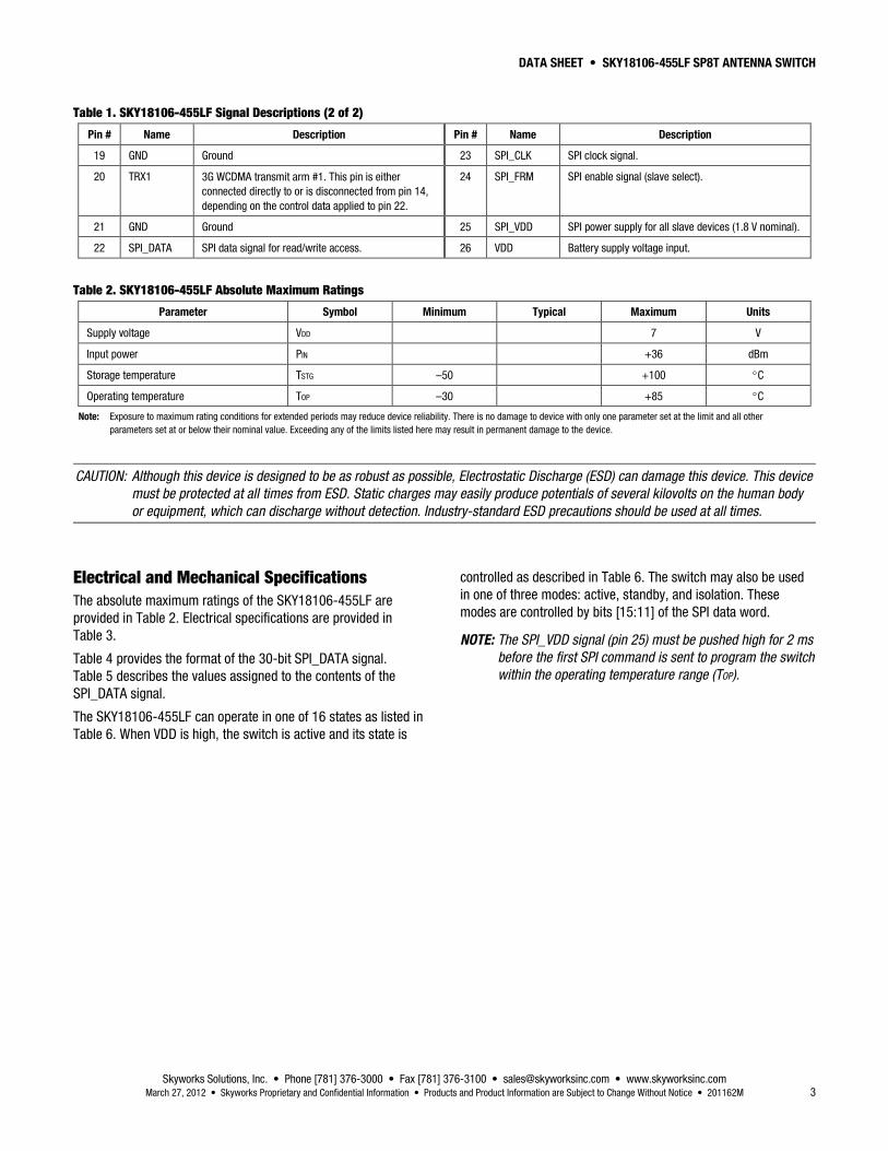
Table 1. SKY18106-455LF Signal Descriptions (2 of 2)
Pin # Name Description Pin # Name Description
19 GND Ground 23 SPI_CLK SPI clock signal.
20 TRX1 3G WCDMA transmit arm #1. This pin is either connected directly to or is disconnected from pin 14, depending on the control data applied to pin 22.
24 SPI_FRM SPI enable signal (slave select).
21 GND Ground 25 SPI_VDD SPI power supply for all slave devices (1.8 V nominal).
22 SPI_DATA SPI data signal for read/write access. 26 VDD Battery supply voltage input.
Table 2. SKY18106-455LF Absolute Maximum Ratings
Parameter Symbol Minimum Typical Maximum Units
Supply voltage VDD 7 V
Input power PIN +36 dBm
Storage temperature TSTG –50 +100 °C
Operating temperature TOP –30 +85 °C
Note: Exposure to maximum rating conditions for extended periods may reduce device reliability. There is no damage to device with only one parameter set at the limit and all other parameters set at or below their nominal value. Exceeding any of the limits listed here may result in permanent damage to the device.
CAUTION: Although this device is designed to be as robust as possible, Electrostatic Discharge (ESD) can damage this device. This device must be protected at all times from ESD. Static charges may easily produce potentials of several kilovolts on the human body or equipment, which can discharge without detection. Industry-standard ESD precautions should be used at all times.
Electrical and Mechanical Specifications The absolute maximum ratings of the SKY18106-455LF are provided in Table 2. Electrical specifications are provided in Table 3.
Table 4 provides the format of the 30-bit SPI_DATA signal. Table 5 describes the values assigned to the contents of the SPI_DATA signal.
The SKY18106-455LF can operate in one of 16 states as listed in Table 6. When VDD is high, the switch is active and its state is
controlled as described in Table 6. The switch may also be used in one of three modes: active, standby, and isolation. These modes are controlled by bits [15:11] of the SPI data word.
NOTE: The SPI_VDD signal (pin 25) must be pushed high for 2 ms before the first SPI command is sent to program the switch within the operating temperature range (TOP).
DATA SHEET • SKY18106-455LF SP8T ANTENNA SWITCH
Skyworks Solutions, Inc. • Phone [781] 376-3000 • Fax [781] 376-3100 • [email protected] • www.skyworksinc.com 4 March 27, 2012 • Skyworks Proprietary and Confidential Information • Products and Product Information are Subject to Change Without Notice • 201162M
Table 3. SKY18106-455LF Electrical Specifications (Note 1) (1 of 2) (VDD = 2.75 V, TOP = +25 °C, SPI_VDD = 1.8 V, All Ports Terminated With a 50 Ω Load, Unless Otherwise Noted)
Parameter Symbol Test Condition Min Typical Max Units
Insertion loss, 2G 2G_TX_LB, 824 to 915 MHz
2G_TX_HB, 1710 to 1910 MHz
0.75
0.90
0.85
1.00
dB
dB
Insertion loss, 2G TOP = +85 °C
2G_TX_LB, 824 to 915 MHz
2G_TX_HB, 1710 to 1910 MHz
0.85
1.00
0.95
1.10
dB
dB
Insertion loss, TRX arms (Band 1) 1920 to 2170 MHz 0.75 0.85 dB
Insertion loss, TRX arms (Band 1) TOP = +85 °C
1920 to 2170 MHz
0.85
0.95
dB
Insertion loss, TRX arms (Bands 2 and 3)
1710 to 1990 MHz 0.7 0.8 dB
Insertion loss, TRX arms (Bands 2 and 3)
TOP = +85 °C
1710 to 1990 MHz
0.8
0.9
dB
Insertion loss, TRX arms (Bands 5 and 8)
824 to 960 MHz 0.50 0.65 dB
Insertion loss, TRX arms (Bands 5 and 8)
TOP = +85 °C
824 to 960 MHz
0.60
0.75
dB
Isolation 2G_TX_LB to ANT, 824 to 915 MHz
2G_TX_HB to ANT, 1710 to 1910 MHz
2G_TX_HB/2G_TX_LB to any TRX port
25
30
25
28
35
30
dB
dB
dB
Isolation, ANT to all “off” TRX ports @ 2170 MHz 20 25 dB
Isolation, TRX to all “off” TRX ports @ 2170 MHz 20 23 dB
Return loss ANT port 15 20 dB
Harmonics 2fo and 3fo 2G_TX_LB to ANT, +35 dBm
2G_TX_LB to ANT, +35 dBm, ANT VSWR = 4:1
2G_TX_HB to ANT, +33 dBm
2G_TX_HB to ANT, +33 dBm, ANT VSWR = 4:1
3G TRX ports to ANT, +26 dBm
3G TRX ports to ANT, +26 dBm, ANT VSWR = 4:1
–46
–36
–46
–36
–55
–50
–42
–33
–42
–33
–50
–45
dBm
dBm
dBm
dBm
dBm
dBm
3rd Order Intermodulation Distortion, all TRX ports to ANT port
IMD3 All blockers, all phase angles, transmit power = +15 dBm, blocker power = –20 dBm
–102 –97 dBm
DATA SHEET • SKY18106-455LF SP8T ANTENNA SWITCH
Skyworks Solutions, Inc. • Phone [781] 376-3000 • Fax [781] 376-3100 • [email protected] • www.skyworksinc.com March 27, 2012 • Skyworks Proprietary and Confidential Information • Products and Product Information are Subject to Change Without Notice • 201162M 5
Table 3. SKY18106-455LF Electrical Specifications (Note 1) (2 of 2) (VDD = 2.75 V, TOP = +25 °C, SPI_VDD = 1.8 V, All Ports Terminated With a 50 Ω Load, Unless Otherwise Noted)
Parameter Symbol Test Condition Min Typical Max Units
Harmonics attenuation (low band) 2fo
3fo
4fo
2nd harmonics attenuation, 2G_TX_LB to ANT
3rd harmonics attenuation, 2G_TX_LB to ANT
4th harmonics attenuation, 2G_TX_LB to ANT
22
24
16
dB
dB
dB
Harmonics attenuation (high band) 2fo
3fo
4fo
2nd harmonics attenuation, 2G_TX_HB to ANT
3rd harmonics attentuation, 2G_TX_HB to ANT
4th harmonics attenuation, 2G_TX_HB to ANT
24
22
16
dB
dB
dB
Switching speed Path to path
Standby to any “on” path
2
6
μs
μs
Supply voltage VDD 2.65 2.75 6.00 V
Supply current: active mode standby mode
IDD 500 3
800
μA μA
Control voltage SPI VDD high
SPI VDD low
SPI control input voltage high
SPI control input voltage low
1.6
–0.3
SPI VDD x 70%
1.8
0
1.8
0
2.0
+0.3
SPI VDD + 0.3
SPI VDD x 30%
V
V
V
V
Voltage Standing Wave Ratio, all ports VSWR 1:2 1:5 –
Inband ripple, all ports 0.2 dB
Note 1: Performance is guaranteed only under the conditions listed in this Table.
Skyworks Solutions, Inc. • Phone [781] 376-3000 • Fax [781] 376-3100 • [email protected] • www.skyworksinc.com 6 March 27, 2012 • Skyworks Proprietary and Confidential Information • Products and Product Information are Subject to Change Without Notice • 201162M
Skyworks Solutions, Inc. • Phone [781] 376-3000 • Fax [781] 376-3100 • [email protected] • www.skyworksinc.com March 27, 2012 • Skyworks Proprietary and Confidential Information • Products and Product Information are Subject to Change Without Notice • 201162M 7
Table 6. SKY18106-455LF Truth Table (SPI_DATA, Bits [15:11])
Evaluation Board The SKY18106-455LF Evaluation Board is used to test the performance of the SKY18106-455LF Antenna Switch. An Evaluation Board schematic diagram is provided in Figure 3. An assembly drawing for the Evaluation Board is shown in Figure 4.
Package Dimensions The PCB layout footprint for the SKY18106-455LF is provided in Figure 5. Typical case markings are shown in Figure 6. Package dimensions for the 26-pin QFN are shown in Figure 7, and tape and reel dimensions are provided in Figure 8.
Package and Handling Information Instructions on the shipping container label regarding exposure to moisture after the container seal is broken must be followed. Otherwise, problems related to moisture absorption may occur when the part is subjected to high temperature during solder assembly.
THE SKY18106-455LF is rated to Moisture Sensitivity Level 1 (MSL1) at 260 °C. It can be used for lead or lead-free soldering. For additional information, refer to the Skyworks Application Note, Solder Reflow Information, document number 200164.
Care must be taken when attaching this product, whether it is done manually or in a production solder reflow environment. Production quantities of this product are shipped in a standard tape and reel format.
DATA SHEET • SKY18106-455LF SP8T ANTENNA SWITCH
Skyworks Solutions, Inc. • Phone [781] 376-3000 • Fax [781] 376-3100 • [email protected] • www.skyworksinc.com 8 March 27, 2012 • Skyworks Proprietary and Confidential Information • Products and Product Information are Subject to Change Without Notice • 201162M
Skyworks Solutions, Inc. • Phone [781] 376-3000 • Fax [781] 376-3100 • [email protected] • www.skyworksinc.com March 27, 2012 • Skyworks Proprietary and Confidential Information • Products and Product Information are Subject to Change Without Notice • 201162M 9
Skyworks Solutions, Inc. • Phone [781] 376-3000 • Fax [781] 376-3100 • [email protected] • www.skyworksinc.com 10 March 27, 2012 • Skyworks Proprietary and Confidential Information • Products and Product Information are Subject to Change Without Notice • 201162M
Skyworks Solutions, Inc. • Phone [781] 376-3000 • Fax [781] 376-3100 • [email protected] • www.skyworksinc.com March 27, 2012 • Skyworks Proprietary and Confidential Information • Products and Product Information are Subject to Change Without Notice • 201162M 11
Figure 8. SKY18106-455LF Tape and Reel Dimensions
DATA SHEET • SKY18106-455LF SP8T ANTENNA SWITCH
Skyworks Solutions, Inc. • Phone [781] 376-3000 • Fax [781] 376-3100 • [email protected] • www.skyworksinc.com 12 March 27, 2012 • Skyworks Proprietary and Confidential Information • Products and Product Information are Subject to Change Without Notice • 201162M
Ordering Information Model Name Manufacturing Part Number Evaluation Board Part Number
Information in this document is provided in connection with Skyworks Solutions, Inc. (“Skyworks”) products or services. These materials, including the information contained herein, are provided by Skyworks as a service to its customers and may be used for informational purposes only by the customer. Skyworks assumes no responsibility for errors or omissions in these materials or the information contained herein. Skyworks may change its documentation, products, services, specifications or product descriptions at any time, without notice. Skyworks makes no commitment to update the materials or information and shall have no responsibility whatsoever for conflicts, incompatibilities, or other difficulties arising from any future changes.
No license, whether express, implied, by estoppel or otherwise, is granted to any intellectual property rights by this document. Skyworks assumes no liability for any materials, products or information provided hereunder, including the sale, distribution, reproduction or use of Skyworks products, information or materials, except as may be provided in Skyworks Terms and Conditions of Sale.
THE MATERIALS, PRODUCTS AND INFORMATION ARE PROVIDED “AS IS” WITHOUT WARRANTY OF ANY KIND, WHETHER EXPRESS, IMPLIED, STATUTORY, OR OTHERWISE, INCLUDING FITNESS FOR A PARTICULAR PURPOSE OR USE, MERCHANTABILITY, PERFORMANCE, QUALITY OR NON-INFRINGEMENT OF ANY INTELLECTUAL PROPERTY RIGHT; ALL SUCH WARRANTIES ARE HEREBY EXPRESSLY DISCLAIMED. SKYWORKS DOES NOT WARRANT THE ACCURACY OR COMPLETENESS OF THE INFORMATION, TEXT, GRAPHICS OR OTHER ITEMS CONTAINED WITHIN THESE MATERIALS. SKYWORKS SHALL NOT BE LIABLE FOR ANY DAMAGES, INCLUDING BUT NOT LIMITED TO ANY SPECIAL, INDIRECT, INCIDENTAL, STATUTORY, OR CONSEQUENTIAL DAMAGES, INCLUDING WITHOUT LIMITATION, LOST REVENUES OR LOST PROFITS THAT MAY RESULT FROM THE USE OF THE MATERIALS OR INFORMATION, WHETHER OR NOT THE RECIPIENT OF MATERIALS HAS BEEN ADVISED OF THE POSSIBILITY OF SUCH DAMAGE.
Skyworks products are not intended for use in medical, lifesaving or life-sustaining applications, or other equipment in which the failure of the Skyworks products could lead to personal injury, death, physical or environmental damage. Skyworks customers using or selling Skyworks products for use in such applications do so at their own risk and agree to fully indemnify Skyworks for any damages resulting from such improper use or sale.
Customers are responsible for their products and applications using Skyworks products, which may deviate from published specifications as a result of design defects, errors, or operation of products outside of published parameters or design specifications. Customers should include design and operating safeguards to minimize these and other risks. Skyworks assumes no liability for applications assistance, customer product design, or damage to any equipment resulting from the use of Skyworks products outside of stated published specifications or parameters.
Skyworks, the Skyworks symbol, and “Breakthrough Simplicity” are trademarks or registered trademarks of Skyworks Solutions, Inc., in the United States and other countries. Third-party brands and names are for identification purposes only, and are the property of their respective owners. Additional information, including relevant terms and conditions, posted at www.skyworksinc.com, are incorporated by reference.
Mouser Electronics
Authorized Distributor
Click to View Pricing, Inventory, Delivery & Lifecycle Information: Skyworks: