ABB has combined the two highly successful flame scanner product lines, Uvisor TM and Safe Flame DFS, into a new advanced Flame Scanner, the Uvisor TM SF810. The Uvisor SF810 is a multi-fuel flame scanner designed to provide absolutely reliable information regarding the presence or absence of a burner flame (The primary purpose of a flame scanner), and at the same time continuously monitors the burner flame quality to provide additional operating information to plant personnel. In a rugged housing, the Uvisor SF810 embeds the solid state sensor modules, covering the complete flame radiant spectrum (UV-to-IR including a dual sensor UVIR). Terminations are available as screw type removable connectors; as quick release connector for IP66/67 or as quick release connector for II 2GD Ex d IIC T 6 hazardous areas. The Uvisor SF810 flame scanner is a vailable with accessories for the following installations: - Line of sight (LOS) for wall fired burners’ boilers - Fiber optic cable (FOC) with outer guide pipe, for corner fired tilting burners’ boilers Application: Utility and Industrial boilers - Wall fired, corner fired, WHRB, down-shot and cyclone burner types Multi fuel - Natural Gas, Coke Oven Gas - Light & heavy fuel oil, Orimulsion - Pulverized coal - Sulphur gas Features: Operation - UV, VL, IR solid stat e sensors - Dual sensor UVIR - Continuous self-check - F-FFRT Fast Flame Fail ure Response Time - ATEX II 2GD Ex d IIC T6 tD A21 IP66 T80°C - Line of sight with accessories to give precise alignment with the flame - Rigid fiber optic cable to improve discrimination performance for deep wind boxes - Flexible fiber optic cable to maintain flame alignment for tilting burner. Symphony Plus Combustion Instruments Multi Fuel Safe Flame Scanner Uvisor ™ SF810 Data sheet
Transcript
ABB has combined the two highly successful fl ame
scanner product lines, UvisorTM and Safe Flame DFS, into
a new advanced Flame Scanner, the UvisorTM SF810.
The Uvisor SF810 is a multi-fuel flame scanner designed
to provide absolutely reliable information regarding the
presence or absence of a burner flame
(The primary purpose of a flame scanner), and at the
same time continuously monitors the burner flame
quality to provide additional operating information to
plant personnel.
In a rugged housing, the Uvisor SF810 embeds the solid
state sensor modules, covering the complete fl ame
radiant spectrum (UV-to-IR including a dual sensor UVIR).
Terminations are available as screw type removable
connectors; as quick release connector for IP66/67 or as
quick release connector for II 2GD Ex d IIC T 6
hazardous areas.
The Uvisor SF810 flame scanner is a vailable with
accessories for the following installations:
- Line of sight (LOS) for wall fired burners’ boilers
- Fiber optic cable (FOC) with outer guide pipe, for corner
fired tilting burners’ boilers
Application:
Utility and Industrial boilers
− Wall fired, corner fired, WHRB, down-shot and cyclone
burner types Multi fuel
− Natural Gas, Coke Oven Gas
− Light & heavy fuel oil, Orimulsion
− Pulverized coal
− Sulphur gas
Features:
Operation
− UV, VL, IR solid stat e sensors
− Dual sensor UVIR
− Continuous self-check
− F-FFRT Fast Flame Fail ure Response Time
− ATEX II 2GD Ex d IIC T6 tD A21 IP66 T80°C
− Line of sight with accessories to give precise alignment
with the flame
− Rigid fiber optic cable to improve discrimination
performance for deep wind boxes
− Flexible fiber optic cable to maintain flame alignment for
tilting burner.
Symphony Plus Combustion InstrumentsMulti Fuel Safe Flame Scanner Uvisor™ SF810
Data sheet
2 Multi Fuel Safe Flame Scanner UvisorTM SF810
Technical specificatios
Property Value
Optical sensor Technology IR versions: Si photodiode Spectral response peak @ 920nm
VL versions: Si photodiode Spectral response peak @ 560nm UV versions: SiC photodiode Spectral response peak @ 280nm
UVIR version: Si + SiC photodiode Spectral response peak @ 280nm and 920nm
Power supply voltage Flame Analysis Unit FAU810 Powered
Power consumption Max 300 mW / 600 mW (Dual Sensor)
Local configuration No
Air source for lens cleaning From clean ambient air
Air flow for lens cleaning LOS (Line Of Sight) versions: 115 l/min (4 SCFM) Excessive contaminants might require a flow up to 400 l/min
6 Cooling air manifold 1" NPTF EC-DWG-G041MEC010-A 1
7 Nipple 1"NPTM / 1" NPTM EC-DWG-G041MEC406-A 1
8 Swivel mounting flange EC-DWG-G041MEC0101-A 1
SF810 flame scannerLine of Sight standard assembly layout and parts
ITEM DESCRIIPTION DETAILED DRAWING NUMBER NOTE Q.ty
1 1
2 1
3 EC-DWG-G041MEC011-A 1
4 ISOLATION VALVE 1
5
UVISOR SF810 FLAME SCANNER
1
6 1
EC-DWG-G041MEC108-A
WINDOWED COVER
7 1
COOLING AIR MANIFOLD 1" NPTF EC-DWG-G041MEC010-A
UVISOR SF810 FLAME SCANNER CASE. LOS Type only
THERMAL UNION
NIPPLE 1"NPTM / R1"
NIPPLE G1"A / R1"
Ref. SF810 / SF810INT codes
EC-DWG-G041MEC405-A
EC-DWG-G041MEC406-A
8 1SWIVEL MOUNTING FLANGE EC-DWG-G041MEC0101-A
1
6
4
5
3
2
87
SF810 assembly layout with fitting
6 Multi Fuel Safe Flame Scanner UvisorTM SF810
SF810 flame scannerLine of Sight standard assembly with cooling cylinder and fitting parts
SF810 assembly layout with cooling cylinder and fitting
1"
NP
TF
70 mm (2,75")
G1
"
Ø6.5
Ø62
Ø72
Ø44
595972
1"
NP
TF
1"
NP
TM
1"
NP
TF
1"
NP
TM
1"
NP
TM
Cable Inlet ¾" NPTF
Cooling Air Inlet G¾"
44 mm Burner plate opening
for scanner Line Of Sight
Bo
iler
Mo
untin
g P
late
A
B
1456 3 2
1"
NP
TM
1"
NP
TM
Item Descriiption Material P/N
1 SF810/SF810i-LOS with Air Cooler DIE CAST ALUMINUM / NYLONSF810 / SF810INT-LOS-XXXX-X-X-X X= Any SF810 / SF810INT series modelEC-DWG-G041-MEC111-A SF810 AIR COOLING CYLINDER
SF810 flame scannerFiber Optic Cable (FOC) standard assembly
Flexible Fiber Optic installation is recommended on those
application where the target burner flame is not visible from
the burner mounting front plate. Flexible fiber optic is also the
preferred solution to relocate the sensor unit wherever heat,
dust and vibration of the burner deck are particularly severe.
Typical application:
− Tilting burner boilers
− Gas turbine
8 Multi Fuel Safe Flame Scanner UvisorTM SF810
Item Descriiption Part number Material Note Q.ty1 1" RIGID MAIN PIPE EC-DWG-G041MEC019-A STEEL UNI EN 10240 12 COOLING AIR MANIFOLD 1" NPTF EC-DWG-G041MEC010-A CAST ALLUMINUM ALLOY 13 MANIFOLD ADAPTER EC-DWG-G041MEC011-A ALLUMINUM ALLOY 14 THERMAL ISOLATOR EC-DWG-G018MEC761-B AISI 321 15 UVISOR SF810/SF810I FLAME SCANNER CAST ALLUMINUM ALLOY WINDOWED HOUSING COVER 16 FIBER OPTIC TERMINAL-COLD SIDE 17a FIBER OPTIC CABLE EC-DWG-G041MEC020-C AISI 321 SINGLE SENSOR IR 17b FIBER OPTIC CABLE EC-DWG-G041MEC021-C AISI 321 SINGLE SENSOR UV 17c FIBER OPTIC CABLE EC-DWG-G041MEC022-C AISI 321 DUAL SENSOR UVIR 18 EXTERNAL GUIDE PIPE TERMINAL EC-DWG-G041MEC012-B AISI 304 19 SEEGER RING INNER 20MM UNI3654-7437 110 BOILER MOUNTING FLANGE EC-DWG-G041MEC015-A FE 360 GALVANIZED 111 BOILER MOUNTING COUNTER FLANGE EC-DWG-G041MEC014-A FE 360 GALVANIZED 112 UVISOR SF810/SF810I FLAME SCANNER CAST ALLUMINUM ALLOY SCANNER HOUSING 113 FIBER OPTIC TERMINAL - HOT SIDE EC-DWG-G041MEC017-B AISI 304 114 LENS RETAINER EC-DWG-G041MEC008-A 115 LENS HOLDER EC-DWG-G041MEC005-C AISI 304 116 LENS EC-DWG-G041MEC006-A 117 LOCKING RING NUT EC-DWG-G041MEC024-A ALLUMINUM ALLOY ANTICORODAL 118 GUIDE COLLAR EC-DWG-G041MEC016-B AISI 304 119 FLEXIBLE HOSE EC-DWG-G041MEC013-B AISI 321 STANDARD LENGTH = 1100MM (43.3") 120 LOADING SPRING EC-DWG-G018MEC771-B 121 VEI_M8X35 SCREW HEXAGON SOCKET. M8 X 35 422 VEI_M8X10 SCREW HEXAGON SOCKET. M8 X 10 223 V5-8--_-_U7688_PZ SCREW TSP.CR PZ UNI 7688 M 5X8 124 NUT_M8-Z NUT M8 UNI 5588 4
NPTF
1
6
4
5
3
2
119
9
10
8
7 a, b, c
14
1513
19
12
20
18
17
16
23
2422
21
Fiber Optic Cable (FOC)Flexible assembly layout and parts
Standard assembly of the SF810 flame scanner model FOC with flexible guide pipe
Multi Fuel Safe Flame Scanner UvisorTM SF810 9
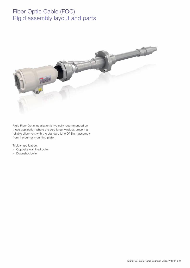
Fiber Optic Cable (FOC)Rigid assembly layout and parts
Rigid Fiber Optic installation is typically recommended on
those application where the very large windbox prevent an
reliable alignment with the standard Line Of Sight assembly
from the burner mounting plate.
Typical application:
− Opposite wall fired boiler
− Downshot boiler
10 Multi Fuel Safe Flame Scanner UvisorTM SF810
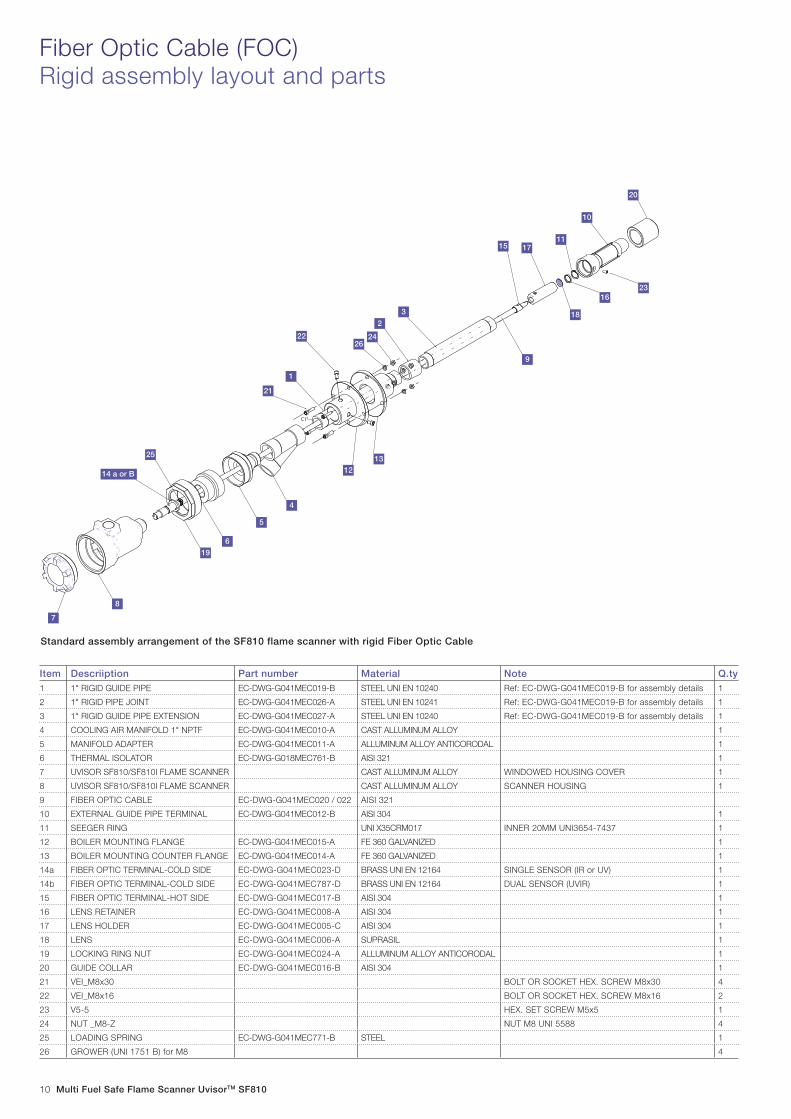
Item Descriiption Part number Material Note Q.ty1 1" RIGID GUIDE PIPE EC-DWG-G041MEC019-B STEEL UNI EN 10240 Ref: EC-DWG-G041MEC019-B for assembly details 1
2 1" RIGID PIPE JOINT EC-DWG-G041MEC026-A STEEL UNI EN 10241 Ref: EC-DWG-G041MEC019-B for assembly details 1
3 1" RIGID GUIDE PIPE EXTENSION EC-DWG-G041MEC027-A STEEL UNI EN 10240 Ref: EC-DWG-G041MEC019-B for assembly details 1
11 SEEGER RING UNI X35CRM017 INNER 20MM UNI3654-7437 1
12 BOILER MOUNTING FLANGE EC-DWG-G041MEC015-A FE 360 GALVANIZED 1
13 BOILER MOUNTING COUNTER FLANGE EC-DWG-G041MEC014-A FE 360 GALVANIZED 1
14a FIBER OPTIC TERMINAL-COLD SIDE EC-DWG-G041MEC023-D BRASS UNI EN 12164 SINGLE SENSOR (IR or UV) 1
14b FIBER OPTIC TERMINAL-COLD SIDE EC-DWG-G041MEC787-D BRASS UNI EN 12164 DUAL SENSOR (UVIR) 1
15 FIBER OPTIC TERMINAL-HOT SIDE EC-DWG-G041MEC017-B AISI 304 1
16 LENS RETAINER EC-DWG-G041MEC008-A AISI 304 1
17 LENS HOLDER EC-DWG-G041MEC005-C AISI 304 1
18 LENS EC-DWG-G041MEC006-A SUPRASIL 1
19 LOCKING RING NUT EC-DWG-G041MEC024-A ALLUMINUM ALLOY ANTICORODAL 1
20 GUIDE COLLAR EC-DWG-G041MEC016-B AISI 304 1
21 VEI_M8x30 BOLT OR SOCKET HEX. SCREW M8x30 4
22 VEI_M8x16 BOLT OR SOCKET HEX. SCREW M8x16 2
23 V5-5 HEX. SET SCREW M5x5 1
24 NUT _M8-Z NUT M8 UNI 5588 4
25 LOADING SPRING EC-DWG-G041MEC771-B STEEL 1
26 GROWER (UNI 1751 B) for M8 4
C1"
9
7
25
6
4
8
22
21
18
11
1
20
15
16
2624
2
3
13
19
12
5
23
10
17
14 a or B
Fiber Optic Cable (FOC)Rigid assembly layout and parts
Standard assembly arrangement of the SF810 flame scanner with rigid Fiber Optic Cable
Multi Fuel Safe Flame Scanner UvisorTM SF810 11
Fiber Optic Cable (FOC) scannersWiring Options
SF810 model FOC with "Quick Release" multipin connector
SF810 model FOC with 3/4" NPTF cable entry and terminal strip
12 Multi Fuel Safe Flame Scanner UvisorTM SF810
Connector / Terminal Signal name Description
+15 V +15 V Power supply positive input from FAU810/DFS Sensor 1 / Sensor 2
-15 V -15 V Power supply negative input from FAU810/DFS Sensor 1 / Sensor 2
GND GND Return of power supply, ground ref. for all internal electronics. Sensor 1 / Sensor 2
OUT Signal Live flame signal. (Single Sensor)
OUT-IR Signal IR Live flame signal (Dual Sensor)
OUT-UV Signal UV Live flame signal (Dual Sensor)
NC NC (Not used)
SHIELD Shield Earth connection point for the shields of the cable(s)
AIMING Green light blinks faster when flame Intensity signal increases
SF810 electrical connections
Dual Sensor Faceplate Single Sensor Faceplate
AIMING
SHIELD
OUT-IR
GND
NC
+15V-15V
OUT-UV
+15V-15V
NCGND
AIMING
GND
OUT
-15V
SHIELD
+15V
NC
Multi Fuel Safe Flame Scanner UvisorTM SF810 13
SF810 Quick Release ConnectorWiring and pin assignment
A (B+)
B (B-)
C (Sg)
D (Cm)
T (Sch)
L2L1
L
Red
Black
Green
White
3/4" FNPT for Cord Gripor Sealtite Connector
AB
C
D
EFGH
J
K
LM
NP
RS
T
Front view malecontacts insert
Cable 4xAWG20/H2-M1
3/4" NPTF - PG11 REDUCTION AND CABLE GLANDNOTE:FOR EX INSTALLATION USE CABLE GLANDS ACCORDING TO EN60079-0 ANNEX "A" AND REFER TO "USE AND MAINTENANCE INSTRUCTIONS IM-IEC-C-076/14.01"
Article Number: SF810-CBL4-YYY
IP66-67 QUICK RELEASE CONNECTOR TYPE "F"ARTICLE NUMBER: Q-17-FYNOTE:FOR EX INSTALLATION USE CVB-EX TYPE CONNECTOR AND REFER TO "USE AND MAINTENANCE INSTRUCTIONS IM-IEC-C-076/14.01"
COMPLETE TAIL CABLE, INCLUDING CIRCULAR CONNECTORARTICLE NUMBER: SF810-CBL4-Q-YYY(SF810-CBL4-QC-YYY FOR EX CONNECTOR)
Table 1 - Single Sensor Connector pin assignment
Tail cable connector pin out (Female)
SF810 T.B. Signal name Tail cable wire color Pig tail fly end label Functional description
A +15V Red A (+B)Power supply +15V from FAU810/DFS
B -15V Black B (-B)Power supply -15V from FAU810/DFS
C SIG Green C (SIG) Live flame signal
D GND White D (Comm)Power supply returnGround reference
E Not used
F Not used
G Not used
H Not used
J Not used
K Not used
L Not used
M Not used
N Not used
P Not used
R Not used
S Not used
T Shield Grey T (Sh) Cable screen grounding
Single Sensor Connector pin assignment with standard ABB cable
Applicable to flame scanner models “Q” and “QC ”. (Refer “SF810 Versions and Ordering Code”, page 19)
14 Multi Fuel Safe Flame Scanner UvisorTM SF810
Dual Sensor Connector pin assignment with standard ABB cable
F (B+)
G (B-)
H (Sg IR)
J (Cm)
T (Sch)
A (B+)
B (B-)
C (Sg UV)
D (Cm)
T (Shd)
L2L1L
Red
Black
Green
White
Red
Black
Green
White
3/4" FNPT for Cord Gripor Sealtite Connector
AB
C
D
EFGH
J
K
LM
NP
RS
T
Front view malecontacts insert
Light blue jacket
White jacket
Cable [2x(4xAWG20/H2)M1]M1
3/4" NPTF - PG11 REDUCTION AND CABLE GLANDNOTE:FOR EX INSTALLATION USE CABLE GLANDS ACCORDING TO EN60079-0 ANNEX "A" AND REFER TO "USE AND MAINTENANCE INSTRUCTIONS IM-IEC-C-076/14.01"
Article Number: SF810-CBL8-YYY
IP66-67 QUICK RELEASE CONNECTOR TYPE "F"ARTICLE NUMBER: Q-17-FY NOTE:FOR EX INSTALLATION USE CVB-EX TYPE CONNECTOR AND REFER TO "USE AND MAINTENANCE INSTRUCTIONS IM-IEC-C-076/14.01"
COMPLETE TAIL CABLE, INCLUDING CIRCULAR CONNECTORARTICLE NUMBER: SF810-CBL8-Q-YYY(SF810-CBL8-QC-YYY FOR EX CONNECTOR)
Table 2 - Dual Sensor Connector pin assignment
Quick connect pinSF810 UVIR Term. Board
Signal name Wires colour Pig tail fly end label Functional description
F 1 +15V Red F (+B) Power supply +15V from FAU810/DFS
G 2 -15V Black G (-B) Power supply -15V from FAU810/DFS
H 3 IR SIG Green H (SIG.IR) Live flame signal IR
J 4 GND White J (Comm)Power supply returnGround reference
E 5 Not used
A 6 +15V Red A (+B) Power supply +15V from FAU810/DFS
B 7 -15V Black B (-B) Power supply -15V from FAU810/DFS
C 8 UV SIG Green C (SIG.UV) Live flame signal UV
D 9 GND White D (Comm)Power supply returnGround reference
K 10 Not used
L Not used
M Not used
N Not used
P Not used
R Not used
S Not used
T Shield Grey T (Sh) Cable screen grounding
SF810 Quick Release ConnectorWiring and pin assignment
Multi Fuel Safe Flame Scanner UvisorTM SF810 15
Grade designation
Sample Ticket No.
Composition Ascertained from Infrared Analysis
Reference Dates
IR TGA DSC
NE075 M211555 CR 08/12/99 02/03/99 06/11/99
Service rating Min. distance air spacing guaranteed Min. distance creepage guaranteed
A 1.6mm 3.2mm
Service rating Operating voltage V D.C. Operating voltage V A.C. Test voltage V A.C. RMS Minimum flashover V A.C. RMS
A 700 500 2000 2800
The following Infrared Spectroscopy (IR), Thermogravimetry
(TGA), and Differential Scanning Calormetry (DSC) tests
were performed in accordance with methods referenced in
the Standard for Polymeric Materials - Short Term Property
Evaluation, UL 746A.
Front view male contacts insert
T
S R
PN
M
L
K
J
H
G
F
E
D
C
B
A Arrangement 20-29
No. of contacts 17
Contacts size 16
Service ratinag A
Rated temperature -55° to 125°C
24
1,5
63
42¾" NPT CH 27
SF810 Quick Release Connector Specification
Cloroprene NE075
16 Multi Fuel Safe Flame Scanner UvisorTM SF810
SF810 wiring diagramSingle Sensor flame scanner
1 2 3 4 5 6 7 8 9 10 11 12 13 14 15 16
17 18 19 20 21 22 23 24 25 26 27 28 29 30 31 32
1NC
1C 1NO
2NC
2C 2NO
3NC
3C 3NO
FAU
810
T
S R
PN
M
L
K
J
H
G
F
E
D
C
B
A
Front view male contacts insert
T
S R
PN
M
L
K
J
H
G
F
E
D
C
B
A
Front view male contacts insert
FAU810 (C10-12010)
CHANNEL 1 FLAME SCANNER CHANNEL 2 FLAME SCANNER
DIRECT CABLE WIRING. SCANNERS TYPE:SF810-XXX-UV/IR-T/TL
DIRECT CABLE WIRING. SCANNERS TYPE:SF810-XXX-UV/IR-T/TL
Tail cable ref: EC-DWG-GO41ELE803
Cable 4xAWG20/H2-M1Article Number: SF810-CBL4-YYY
IP66-67 QUICK RELEASE CONNECTOR TYPE "F"ARTICLE NUMBER: Q-17-FYNOTE:FOR EX INSTALLATION USE CVB-EX TYPE CONNECTOR AND REFER TO "USE AND MAINTENANCE INSTRUCTIONS IM-IEC-C-076/14.01"
COMPLETE TAIL CABLE, INCLUDING CIRCULAR CONNECTORARTICLE NUMBER: SF810-CBL4-Q-YYY(SF810-CBL4-QC-YYY FOR EX CONNECTOR)
COMPLETE TAIL CABLE, INCLUDING CIRCULAR CONNECTORARTICLE NUMBER: SF810-CBL4-Q-YYY(SF810-CBL4-QC-YYY FOR EX CONNECTOR)
Cable 4xAWG20/H2-M1Article Number: SF810-CBL4-YYY
IP66-67 QUICK RELEASE CONNECTOR TYPE "F"ARTICLE NUMBER: Q-17-FYNOTE:FOR EX INSTALLATION USE CVB-EX TYPE CONNECTOR AND REFER TO "USE AND MAINTENANCE INSTRUCTIONS IM-IEC-C-076/14.01"
A (B+)
B (B-)
C (Sg IR)
D (Cm)
T (Sch)
A (B+)
B (B-)
C (Sg IR)
D (Cm)
T (Sch)
SF810 Single Sensor #1 Terminal Board FAU810 Terminal board Signal
+15 V +B (18) +15VDC
-15 V -B (21) -15VDC
OUT IN (19) Live flame signal
GND COM (20) GND
NC NC (not used)
SHIELD Ext. Ground Bar SHIELD
SF810 Single Sensor #2 Terminal Board FAU810 Terminal board Signal
+15 V +B (23) +15VDC
-15 V -B (26) -15VDC
OUT IN (24) Live flame signal
GND COM (25) GND
NC NC (not used)
SHIELD Ext. Ground Bar SHIELD
Wiring Note:
Flame Analysis Unit FAU810 has two (2) configurable sensor input channels. Each channel must be configured for the sensor being connected. Please
refer to FAU810 User Manual for configuration instruction
Multi Fuel Safe Flame Scanner UvisorTM SF810 17
SF810 wiring diagramDual Sensor flame scanner
1 2 3 4 5 6 7 8 9 10 11 12 13 14 15 16
17 18 19 20 21 22 23 24 25 26 27 28 29 30 31 32
1NC
1C 1NO
2NC
2C 2NO
3NC
3C 3NO
FAU
810
F (B+)
G (B-)
H (Sg IR)
J (Cm)
T (Sch)
F (B+)
G (B-)
H (Sg IR)
J (Cm)
T (Sch)
T
S R
PN
M
L
K
J
H
G
F
E
D
C
B
A
Front view male
contacts insert
F (B+)
G (B-)
H (Sg IR)
J (Cm)
T (Sch)
A (B+)
B (B-)
C (Sg UV)
D (Cm)
T (Shd)
Tail cable ref: EC-DWG-GO41ELE802
IP66-67 QUICK RELEASE CONNECTOR TYPE "F"ARTICLE NUMBER: Q-17-FYNOTE:FOR EX INSTALLATION USE CVB-EX TYPE CONNECTOR AND REFER TO "USE AND MAINTENANCE INSTRUCTIONS IM-IEC-C-076/14.01"
COMPLETE TAIL CABLE, INCLUDING CIRCULAR CONNECTORARTICLE NUMBER: SF810-CBL8-Q-YYY(SF810-CBL8-QC-YYY FOR EX CONNECTOR)
SF810 UVIR Terminal Board FAU810 Terminal board Signal
+15V +B (18) +15VDC
-15V -B (21) -15VDC
Out_IR IN (19) Live flame signal IR
GND COM (20) GND
NC NC (not used)
SHIELD Ext. Ground Bar SHIELD
+15V +B (23) +15VDC
-15V -B (26) -15VDC
Out_UV IN (24) Live flame signal UV
GND COM (25) GND
NC NC (not used)
Wiring Note:
Flame Analysis Unit FAU810 has two (2) configurable sensor input channels. Each channel must be configured for the sensor being connected. Please
refer to FAU810 User Manual for configuration instruction
18 Multi Fuel Safe Flame Scanner UvisorTM SF810
Flame scanners application table
Fuel
Scanner
Gas (Hydrogen,Propane, NG)
Oil (Heavy Oil with steam atomisation)
Oil & Gas Low NOx PulverizedCoal/Oil & Coal
Gas/Lightfuel oilPilot
GasTurbine
Notes
W . F T . F W . F T . F W . F T . F W . F T . F D . S
SF810 -LOS-IR Stable signal and excellent target flame
discrimination in wall and cornered fired multi burner boiler. Side Igniters and GT application can also be supported.SF810 -
FOC-IR
SF810 -LOS-VL Stable signal and excellent target flame
discrimination in wall and CF fired multi burner boiler. Side igniters and GT application can also be supported.SF810 -
FOC-VL
SF810 -LOS-UV Stable signal and excellent target flame
discrimination in wall and CF fired multi burner boiler. Side igniters and GT application can also be supported.SF810-
FOC-UV
SF810 -LOS-UVIR Stable signal and excellent target flame
discrimination in the whole operating range. Recommended in combined fuel operation.SF810 -
FOC-UVIR
Abbreviation and symbols:
W.F Wall Fired Boilers
D.S Down Shot Boilers
T.F Tangential Fired Boilers
FOC Fiber Optic Cable (Through the windbox)
LOS Line of Sight (Direct view)
Acceptable Performance
Good performance
Excellent performance
Multi Fuel Safe Flame Scanner UvisorTM SF810 19
Assembly type Article number Description
SF810-FOC all models Lens SF810-FOC 19mm Quartz Lens for SF810(i)
SF810-FOC all models Lens holder SF810-FOC SF810 FOC Lens Holder with Seeger ring and retainer
SF810-IR all models SF810_IR Card PCB IR Sensor for SF810-IR Flame Scanner
SF810-UV all models SF810_UV Card PCB UV Sensor for SF810-IR Flame Scanner
SF810-UVIR all models SF810_UVIR Card PCB UVIR Sensor for SF810-IR Flame Scanner
Spare Parts
ABB SF810 SafeFlame Scanner is offered with several mounting
and wiring options to suite customer needs. The standard
version comes with removable terminals. Quick release
connector and preassembled connecting cable is also available.
Contact your local ABB organization for additional details.
Feature Available models Uvisor SF810 ordering codes
Installation typeFOC (Scanner head for Fiber Optic Cable)
LOS (Scanner head for Line Of Sight)
Spectral range
IR
UV
VL
IR+UV (dual sensor)
Cabling method, protection index, hazardous areas
Removable screw terminals IP66/IP67 - EX
Removable screw terminals IP66/IP67
Quick-release connector IP66/IP67
Quick-release connector IP66/IP67 - EX
Housing Stainless steel AISI316 case
Notes
IP66/IP67 and EX certificates on FOC assemblies are guaranteed only withABB fiber optic cable P/N:- EC-DWG-G041MEC020- EC-DWG-G041MEC021- EC-DWG-G041MEC022
SF810 - - -FOC ...... ...
SF810 - - -LOS ...... ...
SF810 - - - ......... IR
SF810 - - - ......... UV
SF810 - - - ......... VL
SF810 - - - ......... UVIR
SF810 - - -...... ...... T
SF810 - - -...... ...... TL
SF810 - - -...... ...... Q
SF810 - - -...... ...... QC
SF810Versions and ordering codes
SF810 - - -...... ...... TX
20 Multi Fuel Safe Flame Scanner UvisorTM SF810
Feature Available choices Article number
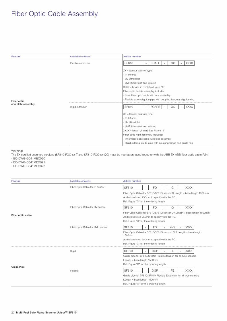
Fiber opticcomplete assembly
XX = Sensor scanner type:
- IR Infrared
- UV Ultraviolet
- UVIR Ultraviolet and Infrared
XXXX = length (in mm) See Figure “A”
Fiber optic flexible assembly includes:
- Inner fiber optic cable with lens assembly
- Flexible external guide pipe with coupling flange and guide ring
XX = Sensor scanner type:
- IR Infrared
- UV Ultraviolet
- UVIR Ultraviolet and Infrared
XXXX = length (in mm) See Figure “B”
Fiber optic rigid assembly includes:
- Inner fiber optic cable with lens assembly
- Rigid external guide pipe with coupling flange and guide ring
Feature Available choices Article number
Fiber optic cable
Fiber Optic Cable for SF810/SF810i sensor IR Length = base length 1500mm
Addintional step 250mm to specify with the PO.
Ref. Figure "C" for the ordering length
Fiber Optic Cable for SF810/SF810i sensor UV Length = base length 1500mm
Addintional step 250mm to specify with the PO.
Ref. Figure "C" for the ordering length
Fiber Optic Cable for SF810/SF810i sensor UVIR Length = base length 1500mm
Addintional step 250mm to specify with the PO.
Ref. Figure "C" for the ordering length
Guide Pipe
Guide pipe for SF810/SF810i Rigid Extension for all type sensors
Length = base length 1500mm
Ref. Figure "B" for the ordering length
Guide pipe for SF810/SF810i Flexible Extension for all type sensors
Length = base length 1500mm
Ref. Figure "A" for the ordering length
Fiber Optic Cable Assembly
SF810 - -FOAFE - XXXXXX
Warning:
The EX certifi ed scanners versions (SF810-FOC-xx-T and SF810-FOC-xx-QC) must be mandatory used together with the ABB EX ABB fi ber optic cable P/N:
- EC-DWG-G041MEC020
- EC-DWG-G041MEC021
- EC-DWG-G041MEC022
Fiber Optic Cable for IR sensor
Fiber Optic Cable for UV sensor
Fiber Optic Cable for UVIR sensor
Flexible extension
Rigid
Flexible
Rigid extension SF810 - -FOARE - XXXXXX
SF810 - -FO - XXXXG
SF810 - -FO - XXXXQ
SF810 - -FO - XXXXGQ
SF810 - -OGP - XXXXRE
SF810 - -OGP - XXXXFE
Multi Fuel Safe Flame Scanner UvisorTM SF810 21
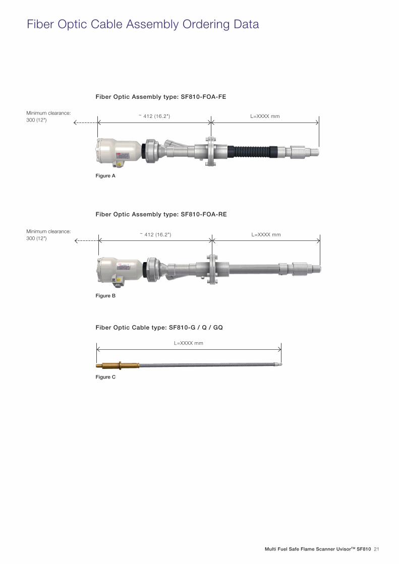
Figure B
L=XXXX mm
Fiber Optic Assembly type: SF810-FOA-RE
Figure A
L=XXXX mm
Fiber Optic Cable Assembly Ordering Data
Minimum clearance:
300 (12")
Minimum clearance:
300 (12")
L=XXXX mm
Fiber Optic Cable type: SF810-G / Q / GQ
Fiber Optic Assembly type: SF810-FOA-FE
Figure C
~ 412 (16.2")
~ 412 (16.2")
22 Multi Fuel Safe Flame Scanner UvisorTM SF810
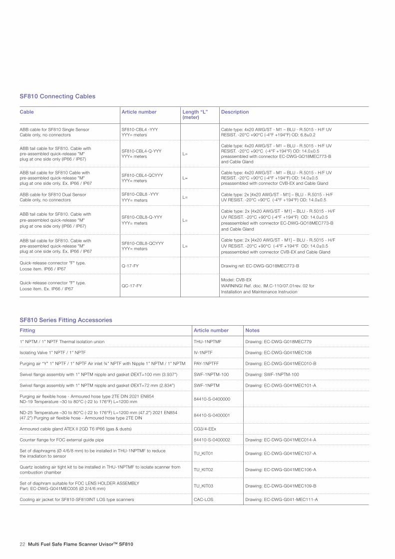
Cable Article number Length “L” (meter)
Description
ABB cable for SF810 Single SensorCable only, no connectors
Counter flange for FOC external guide pipe 84410-S-0400002 Drawing: EC-DWG-G041MEC014-A
Set of diaphragms (Ø 4/6/8 mm) to be installed in THU-1NPTMF to reducethe irradiation to sensor
TU_KIT01 Drawing: EC-DWG-G041MEC107-A
Quartz isolating air tight kit to be installed in THU-1NPTMF to isolate scanner fromcombustion chamber
TU_KIT02 Drawing: EC-DWG-G041MEC106-A
Set of diaphram suitable for FOC LENS HOLDER ASSEMBLYPart: EC-DWG-G041MEC005 (Ø 2/4/6 mm)
TU_KIT03 Drawing: EC-DWG-G041MEC109-B
Cooling air jacket for SF810-SF810INT LOS type scanners CAC-LOS Drawing: EC-DWG-G041-MEC111-A
SF810 Series Fitting Accessories
SF810 Connecting Cables
Multi Fuel Safe Flame Scanner UvisorTM SF810 23
Thermal Union with Quartz Isolation P/N: EC-DWG-G041MEC104
Quartz Isolation Kit P/N: EC-DWG-G041MEC106
Line of Sight (LOS) AssemblyFitting options
The quartz isolation plate is used to interpose an additional seal between the flame scanner and the furnace through the sight
tube. It prevents the furnace pressure and heat from wearing the scanner viewing lens. Article number: TU_KIT02
Ø32
SEEGER type “V”
for hole Ø 32
4
1"
NP
T
Ø24
GASKET O-RING 134 (25,8x3,53) SILICONE 70
1"NPT
QUARTZ PLATE
HERASIL 3
Ø32
for hole Ø32
4
GASKET O-RING 134
(25,8x3,53) SILICONE 70
QUARTZ PLATEHERASIL 3
-0,20-0,10
SEEGER type “V”
24 Multi Fuel Safe Flame Scanner UvisorTM SF810
Thermal Union with orifi ce P/N: EC-DWG-G041MEC105
Orifi ce Kit P/N: EC-DWG-G041MEC107
The use of orifice, available with different size, restricts the field of view (target area) and increase discrimination between target
flame and adjacent, opposite or background radiation. The orifice is firmly secured in the thermal union and is prevented from
falling apart. Once inst alled, assure the performance within the burner operation range . Article number: TU_KIT01
32
4
1" N
PT
GASKET O-RING 134 (25,8x3,53) SILICONE 70
SEEGER type "V"for hole 32
N° 5 BRASS ORIFICE(HOLES 2;4;6;8;10 mm)
24 1"N
PT
A A A
B
B
B
Ø32
SEEGER type “V”
fo r hole Ø32
4
(25,8x3,53) SILICONE 70
N° 5 BRASS ORIFICE
(HOLES 2;4;6;8;10 mm)
GASKET O-RING 134
Multi Fuel Safe Flame Scanner UvisorTM SF810 25
Boiler mounting counter fl ange for FOC assemblies P/N: EC-DWG-G041MEC014
Orifi ce Kit for fl exible and rigid FOC assemblies
The use of orifice, available with different size, restricts the field of view (target area) and increase discrimination between target flame
and adjacent, opposite or background radiation. The orifice is firmly secured in the lens holder assembly and is preventer from falling
apart. Once installed, assure the performance within the burner operation range. Article number: TU_KIT03
The boiler mounting counter flange matches the mounting flange of the standard FOC assemblies (Ref. figures A and B).
WARNING! This flange has a galvanic treatment. Following the applicable recommendation for welding, operator is recommended to wear an FFP2
dust mask. Preliminary remove the Zinc from the welding surface(s). Weld the Zinc-free carbon-steel surfaces and restore the corrosion resistance
with high in elemental zinc (i.e., "Zinc-rich") paint. This paint can be applied to the weld after wire brushing to remove all welding slag followed by
wiping the weld clean with a rag. Article number: 84410-S-0400002
Sec. A-A'A
A'
Ø19.8
Material: Stainless Steel AISI-3042 mm orifice shown. Min. hole 2 mm / Max hole 10 mm