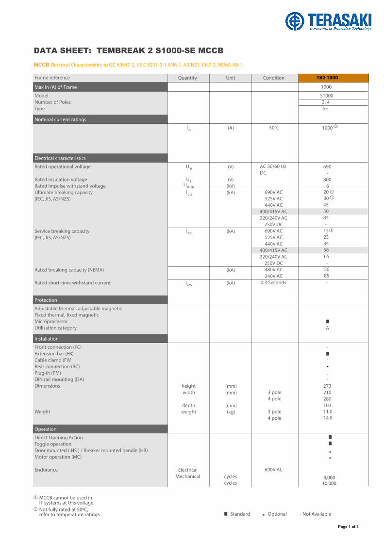
Frame reference Standard • Optional - Not Available S1000 3, 4 SE 1000 690 - 800 8 20 30 45 50 85 - 15 23 34 38 65 - 30 85 - - - A • • • - - 273 210 280 103 11.0 14.8 I n U e U i U imp I cu I cs I cw height width depth weight Electrical Mechanical (A) (V) (V) (kV) (kA) (kA) (kA) (kA) (mm) (mm) (mm) (kg) cycles cycles 4,000 10,000 Quantity Unit Condition TB2 1000 1000 50°C AC 50/60 Hz DC 690V AC 525V AC 440V AC 400/415V AC 220/240V AC 250V DC 690V AC 525V AC 440V AC 400/415V AC 220/240V AC 250V DC 480V AC 240V AC 0.3 Seconds 3 pole 4 pole 3 pole 4 pole 690V AC Max In (A) of Frame Model Number of Poles Type Nominal current ratings Electrical characteristics Rated operational voltage Rated insulation voltage Rated impulse withstand voltage Ultimate breaking capacity (IEC, JIS, AS/NZS) Service breaking capacity (IEC, JIS, AS/NZS) Rated breaking capacity (NEMA) Rated short-time withstand current Protection Adjustable thermal, adjustable magnetic Fixed thermal, fixed magnetic Microprocessor Utilisation category Installation Front connection (FC) Extension bar (FB) Cable clamp (FW Rear connection (RC) Plug-in (PM) DIN rail mounting (DA) Dimensions Weight Operation Direct Opening Action Toggle operation Door mounted ( HS ) / Breaker mounted handle (HB) Motor operation (MC) Endurance MCCB cannot be used in IT systems at this voltage Not fully rated at 50ºC, refer to temperature ratings Page 1 of 3 2 MCCB Electrical Characteristics to IEC 60947-2, JIS C 8201-2-1 ANN 1, AS/NZS 3947-2, NEMA AB-1 DATA SHEET: TEMBREAK 2 S1000-SE MCCB 1 1 1 2 1
MCCB cannot be used in IT systems at this voltageNot fully rated at 50ºC, refer to temperature ratings
Page 1 of 3
2
MCCB Electrical Characteristics to IEC 60947-2, JIS C 8201-2-1 ANN 1, AS/NZS 3947-2, NEMA AB-1
DATA SHEET: TEMBREAK 2 S1000-SE MCCB
11
1
2
1
HLHL HL
HL HL
HL HL
HL
8
ASL
117
127.5
ø13
45
103
28 13
145
25 8
32 20 126
13
80.5
ø13
45
25 8
32 20
13
117
3PHL
4PHL
HLHL
HL 3PHL
4PHL
ø48
ø15
(15.
5)
263
126
117
160 15
6101.
9
26
55
103
122
137.516
140
(19.8)
(18)
200.512.5
213
99.5 43434343 7070707070
1328
70 70
(15.
5)
(19.8)
(18)
ø13
101.
9
101.
9
126
117
160
160 15
6
110
25 83215
8027
380 140
16 137.5
13
12.5 200.5
213
99.5
1328
70
45
3214
3714
280175105
707070
210140
136
ASL ASL ASL ASL
ASL ASL ASL
ASL
HL
8 16
200.
5
100100
200200150150
ASLASL
4P3P
ASL
3P 4P
3P 4P
ASL ASL ASL
Drilling plan (front view) Panel cutout (front view)
Drilling plan (front view)
Conductor overlap, max
M8Tapped hole
M8Tapped hole
Interpole barrier (removable) Mounting hole
M8Mounting screw
M8Mounting screw
Panel cutout dimensions shown give an allowance of 1.0mm around the handle escutcheon.
Trip button (red)
Toggle extension (removable)
Toggle extension(removable)
Vertical direction only ø15 for accessory wiring
when necessary
Groove for dissipating heat generated by overcurrent
Drilling plan (front view)
Connector plug
Front Panel
Front Panel
Interpole barrier(removable)
M8Mounting screw
Panel cutout dimensions shown give an allowance of 1.5mm around motor operator.
M8Tapped hole
M8Tapped hole
Mounting hole
Drilling plan (front view)
Panel cutout (front view)
Cond
ucto
r ov
erlap
, max
Note: Studs are factory installed in horizontal direction both on the line and load sides.
Manual operating handle (removable)
Manual operating handle (removable)
M8 Mounting screw
Pad lock
Pad lock
Connector plug
ø15 for accessory wiring when necessary
Panel hinge position (hatching area)(bottom view)
Conductor overlap, max
Vertical direction only
Conductor overlap, max
3P4P
172
92 R6
70 70 70 70 70 43 43 43 43
117
126
1
36
5
127
5
30.
5
ø48
ø13
70 70
3P4P
140 210
70 70 70 105 175
280
70
45
13
70 80
273
8
0
15
32 8 25
55
.5 46
.5
110
117
126
141
1
32
170
51
90
103
145
28 13
127.5 80.5
51
170
14 32
14 37
Front connected
Rear connected
Front connected with Motor Operator
Rear connected with Motor Operator
8
103
1
22
1270 70 70
1270 70 70
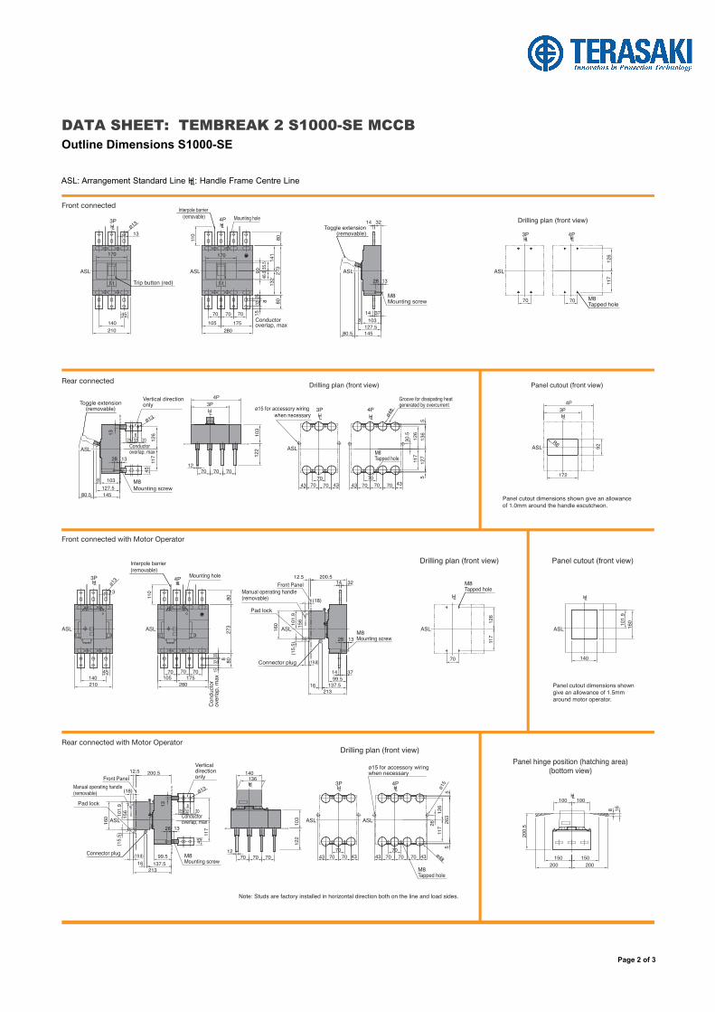
DATA SHEET: TEMBREAK 2 S1000-SE MCCB Outline Dimensions S1000-SE
ASL: Arrangement Standard Line HL: Handle Frame Centre Line
Page 2 of 3
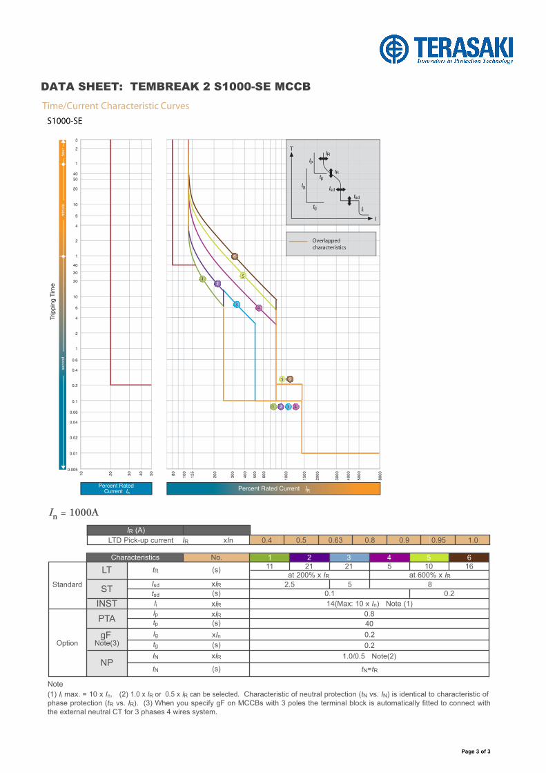
Note(1) Ii max. = 10 x In. (2) 1.0 x IR or 0.5 x IR can be selected. Characteristic of neutral protection (tN vs. IN) is identical to characteristic of phase protection (tR vs. IR). (3) When you specify gF on MCCBs with 3 poles the terminal block is automatically fitted to connect with the external neutral CT for 3 phases 4 wires system.
Thermal Magnetic Characteristics and AdjustmentsTime, Current & Temperature Curves