AbstractAn important research subject in Software engineering is concerned with modelling the develop-ment process of huge software in order to bring some help to engineers when designing and main-taining an application. In general, every design process is seen a rational application of transforma-tion operators to one or more products (mainly specifications) in order to produce new productsthat satisfy some given criteria: O=f(I). I and O being sets of products compliant with formalisablemodels, f is a transformation composition whose specifications are the properties of I and O. Thismodelling is a sound basis for a methodological guidance. Indeed, at each step of the process, theset of pertinent activities and types of products are proposed to the designer, without any other.This guidance can be reinforced with some help. Furthermore, this modelling allows to documentthe process with its history, i.e. with a representation of performed activities. This history is itselfthe basis of maintenance activities.
The thesis holds in four phases:
• elaboration of a general model of design processes, a method specification language (MDL), anda history representation
• basic methodological recommendation proposals for the elaboration of engineering methodsaccording to the defined model
• development and integration of some methodological control functions in the DB-MAINCASE tool, including an extension of the repository, the definition of the interface of the meth-odological functions, the development of the methodological engine and the development ofhistory processors (recording, replay, analysis,...)
• evaluation of this model with case studies using classical methods.
RésuméUn sujet de recherche important dans le monde de l’ingénierie logicielle concerne la modélisationdes processus de développement de grosses applications afin d’apporter de l’aide aux ingénieurspour concevoir et maintenir leurs applications. En général, chaque processus de conception est vucomme l’application rationnelle d’opérateurs de transformation à un ou plusieurs produits (généra-lement des spécifications) pour obtenir de nouveaux produits qui satisfont un ensemble défini decritères: S=f(E). E et S étant des ensembles de produits conformes à des modèles formalisables, f estune composition de transformations dont les spécifications sont les propriétés de E et S. Cettemodélisation permet, principalement, un suivi méthodologique. En effet, à chaque étape du proces-sus, seul l’ensemble des outils pertinents est mis à la disposition du concepteur. Ce guidage peutéventuellement être renforcé par des messages d’aide. De plus, cette modélisation permet de docu-menter le processus avec son historique, c’est-à-dire avec une représentation des actions entreprises.Cet historique peut lui-même être à la base d’activités de maintenance.
La thèse tient en quatre parties :
• élaboration d’un modèle général pour la définition de processus d’ingénierie, d’un langage despécification de méthodes (MDL) et d’une représentation des historiques;
• propositions de recommandations méthodologiques pour l’élaboration de méthodes d’ingénierieselon le modèle défini;
• développement et intégration de fonctions de contrôle méthodologique dans l’atelier DB-MAIN; ceci inclut l’extension du référentiel, la définition de l’interface homme-machine pourles fonctions méthodologiques, le développement du moteur méthodologique et le développe-ment de processeurs d’historiques (enregistrer, rejouer, analyser,...);
• évaluation de ce modèle avec des études de cas utilisant des méthodes classiques.
iv
v
Acknowledgement
This thesis is the result of a long work. A long time during which I met many people whohelped me and who showed some interest. All these people deserve to be thanked.
First of all I want to Thank Jean-Luc Hainaut, with who I did all the job. I want to thankhim for the opportunity he gave to me, for his support and for his availability in the frame-work of this thesis, but also for his great job in founding and leading the LIBD researchteam. I want to thank all this team too, including its present and former members, for theirsupport and collaboration. In particular, many thanks to Jean Henrard, Jean-Marc Hickand Vincent Englebert for the great job we did in the DB-MAIN project, and to VirginieDetienne with who I also worked on another interesting project.
Many thanks to all the other people from the Insistut d'Informatique and from many otherresearch labs for all the interesting discussion I had with them all. I will not list them allbecause I should fill several pages with all their names, but they can really be sure I do notforget them.
Many thanks to the readers of this thesis and to the members of the jury for their interestin it.
I also want to thank all the friends and family members who supported me along the years.Special thanks to Raoudha who particularly supported me along the whole work while pre-paring her own PhD and to Xia who particularly supported me in the last months. Manythanks to Renaud, Lysia, Sivilay, Olfa and many other friends who also supported me a lot.
But this thesis could not have been written if I had not received a very good educationbefore. For this education, and for supporting me all the time from my birth, many, many,many thanks to my parents. Many thanks too to all my other family members (in thebroader sense) and to all the people who participated to this education, including all theteachers at kindergarten, primary school, secondary school, and all the years at universitybefore PhD.
1.2. State of the art and related works 31.2.1. History of data and process engineering 31.2.2. Process modelling in the large 41.2.3. CASE tools and meta-CASE tools 71.2.4. History recording 7
1.3. Database specifics 8
1.4. Goals 9
1.5. Structure of the thesis 10
1.6. DB-MAIN 11
Part 1Part 1Part 1Part 1Models and MethodsModels and MethodsModels and MethodsModels and Methods 13131313
3.2. The GER model 253.2.1. Schema 253.2.2. Entity types 263.2.3. Relationship types (rel-types) 263.2.4. Attributes 263.2.5. Roles 273.2.6. Constraints 283.2.7. Is-a relations 313.2.8. Processing units 323.2.9. Collections 323.2.10. Dynamic properties 32
3.3. Schema model 33
3.4. Text model 45
viii
3.5. Product model hierarchies 47
Chapter 4 Chapter 4 Chapter 4 Chapter 4 Product types and process typesProduct types and process typesProduct types and process typesProduct types and process types 49494949
4.1. Defining product types 50
4.2. Modelling engineering process types 514.2.1. Engineering process type decomposition 514.2.2. Engineering process type interface 524.2.3. Engineering process type strategy 55
4.3. Comparison with other modelling techniques 70
Chapter 5 Chapter 5 Chapter 5 Chapter 5 The MDL languageThe MDL languageThe MDL languageThe MDL language 73737373
5.1. Requirements 74
5.2. Language definition 745.2.1. Generalities 745.2.2. Method 755.2.3. Product Models 765.2.4. Global product types 795.2.5. Toolboxes 805.2.6. External function declarations 815.2.7. Process types 82
5.3. Language analysis 965.3.1. The syntax is unambiguous 975.3.2. Syntactical analysis 985.3.3. The semantics is unambiguous 995.3.4. Compliance with the requirements 99
Part 2Part 2Part 2Part 2HistoriesHistoriesHistoriesHistories 101101101101
6.3. Structure of histories 1066.3.1. Products 1066.3.2. Processes 1076.3.3. Primitive processes 1076.3.4. Engineering processes 1126.3.5. Decisions 1136.3.6. The history of a project 114
ix
6.4. History representation 1166.4.1. Representation of the tree structure 1166.4.2. Representation of primitive process histories 1166.4.3. Representation of engineering process graphs 117
6.5. History construction 1206.5.1. Primitive processes 1206.5.2. Engineering processes 1206.5.3. Hypotheses, versions and decisions 121
7.2. History replay 1267.2.1. Replaying primitive processes of automatic basic type 1267.2.2. Replaying primitive processes of automatic configurable type 1267.2.3. Replaying primitive processes of automatic user configurable type 1267.2.4. Replaying primitive processes of manual type 1267.2.5. Replaying every primitive processes 1287.2.6. Replaying engineering processes 129
7.3. History evolution 129
7.4. History transformation 1327.4.1. History characteristics 1327.4.2. Excerpts 1357.4.3. Independent history excerpts 1367.4.4. Equivalent history excerpts 1377.4.5. Minimal history excerpts 1377.4.6. Operations on history excerpts 1377.4.7. History transformation 139
7.5. History cleaning 1397.5.1. History cleaning 1407.5.2. Primitive process history cleaning 1407.5.3. Engineering process history cleaning 142
7.6. History flattening 143
7.7. History inversion 145
Part 3Part 3Part 3Part 3In practiceIn practiceIn practiceIn practice 147147147147
9.1. Requirements 1629.1.1. Method development environment requirements 1629.1.2. CASE environment requirements 163
9.2. HMI proposals 1669.2.1. Method development environment 1679.2.2. Method visualisation and browsing 1689.2.3. Following a method 1709.2.4. Recording a history 1789.2.5. Complementary tools 1819.2.6. Configuring the CASE environment 1869.2.7. Browsing through a history 1879.2.8. History replay and transformation 187
10.2. The repository 19110.2.1. Notations 19210.2.2. The original repository of the DB-MAIN CASE environment 19210.2.3. The repository extension 193
10.3. Parsing an MDL source file 202
10.4. The GUI 20310.4.1. Loading a method 20310.4.2. History window extension 20310.4.3. The methodological engine 20410.4.4. The GUI look and feel 204
10.5. The methodological engine 20710.5.1. Following a method 20710.5.2. Product and expression evaluation 209
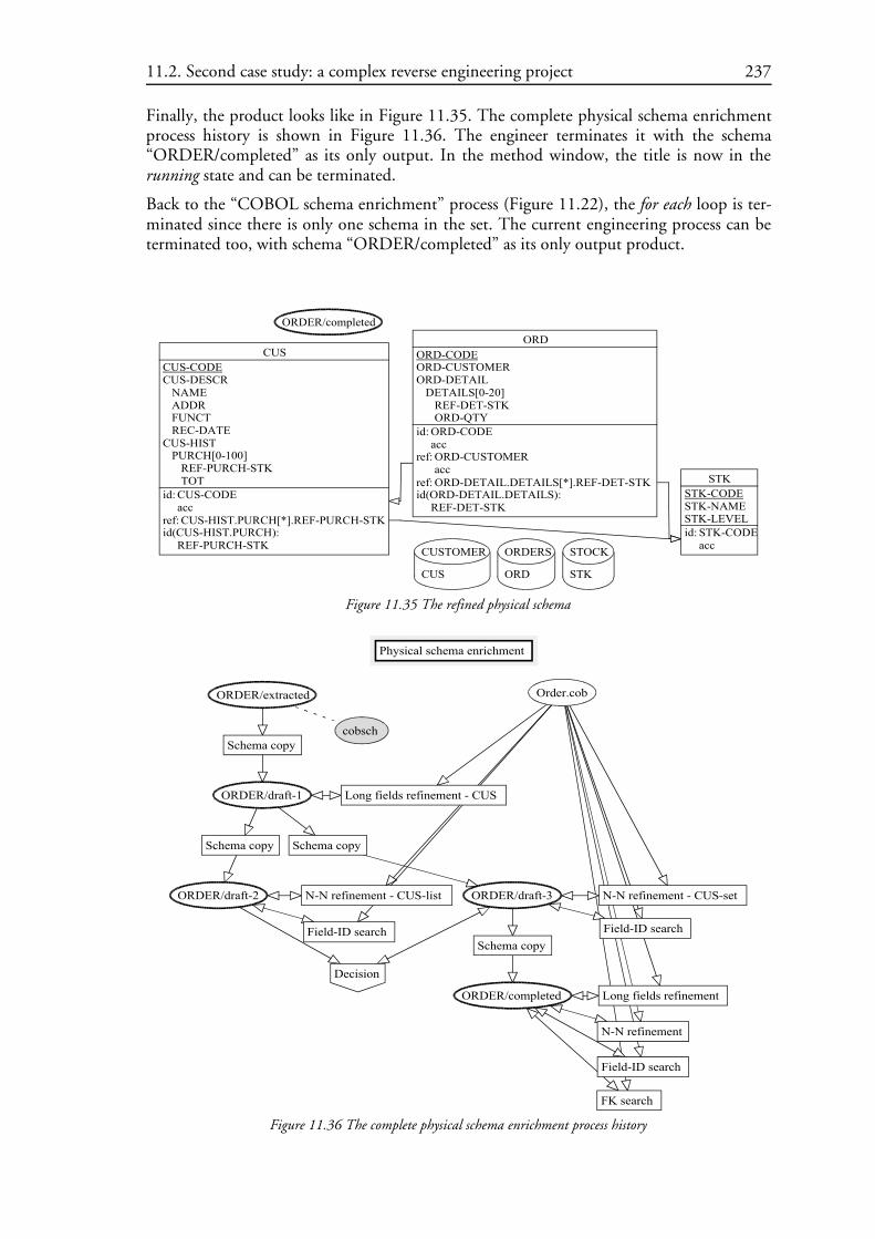
11.1. First case study: a simple forward engineering project 21211.1.1. Defining the method 21211.1.2. Performing the project 21611.1.3. The resulting history 222
11.2. Second case study: a complex reverse engineering project 22311.2.1. Method description 22311.2.2. Project performance 22911.2.3. The resulting history 23911.2.4. Design recovery 241
11.3. Conclusion 241
Chapter 12 Chapter 12 Chapter 12 Chapter 12 Professional useProfessional useProfessional useProfessional use 247247247247
13.2. The problem 25413.2.1. Product models and product types 25413.2.2. Process types 25513.2.3. The method evolution problem 255
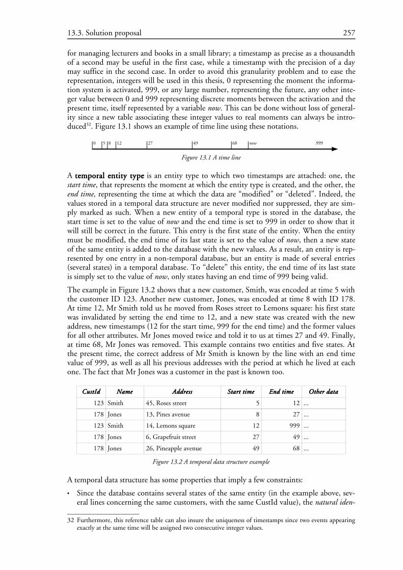
13.3. Solution proposal 25613.3.1. Temporal databases 25613.3.2. A solution proposal for the method evolution problem 260
Chapter 14 Chapter 14 Chapter 14 Chapter 14 Conclusion and future worksConclusion and future worksConclusion and future worksConclusion and future works 263263263263
14.1. Conclusion 263
14.2. Future works 26414.2.1. Method evolution implementation 26414.2.2. Method engineering methodology 26414.2.3. Method recovery 26514.2.4. Graphical method development environment 26514.2.5. Extending to software engineering in general 26614.2.6. Supporting a Meta-CASE 26614.2.7. Supporting co-operative design 266
Appendix A Appendix A Appendix A Appendix A Schema analysis predicatesSchema analysis predicatesSchema analysis predicatesSchema analysis predicates 277277277277
A.1. Constraints on schema 277
A.2. Constraints on collections 277
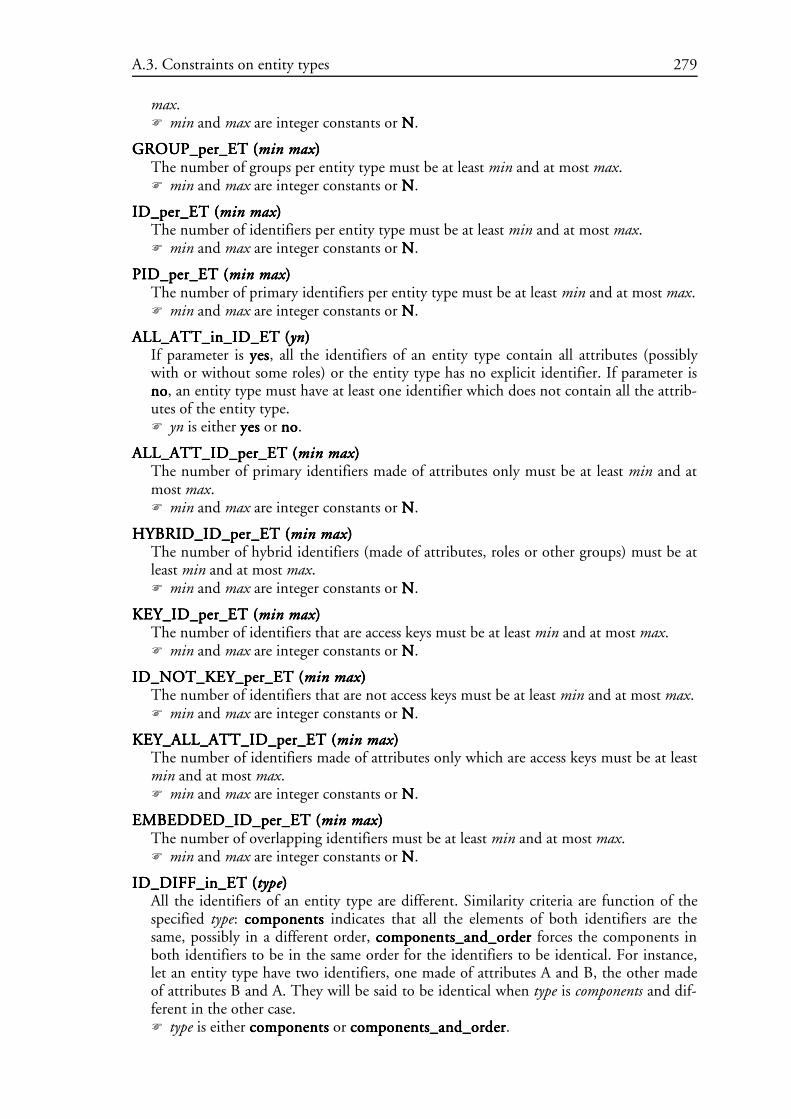
A.3. Constraints on entity types 278
A.4. Constraints on is-a relations 281
A.5. Constraints on rel-types 282
A.6. Constraints on roles 284
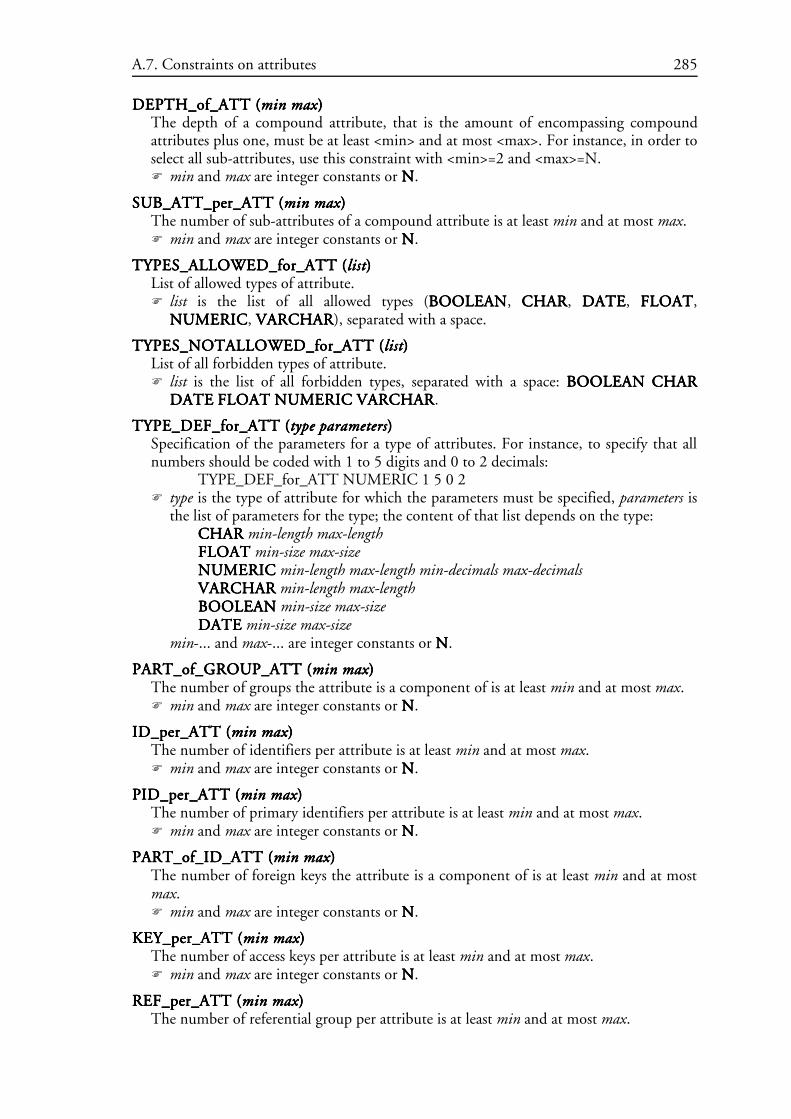
A.7. Constraints on attributes 284
A.8. Constraints on groups 286
xii
A.9. Constraints on entity type identifiers 287
A.10. Constraints on rel-type identifiers 290
A.11. Constraints on attribute identifiers 293
A.12. Constraints on access keys 295
A.13. Constraints on referential groups 296
A.14. Constraints on processing units 298
A.15. Constraints on names 298
A.16. Using DYN_PROP_OF_... constraints 300
A.17. Using Voyager 2 constraints 302
Appendix B Appendix B Appendix B Appendix B The PDL syntaxThe PDL syntaxThe PDL syntaxThe PDL syntax 303303303303
B.1. BNF notation 303
B.2. The PDL language 303
Appendix C Appendix C Appendix C Appendix C Global transformationsGlobal transformationsGlobal transformationsGlobal transformations 305305305305
C.1. Transformations 305
C.2. Control structures 307
Appendix D Appendix D Appendix D Appendix D The MDL syntaxThe MDL syntaxThe MDL syntaxThe MDL syntax 309309309309
Appendix E Appendix E Appendix E Appendix E DB-MAIN functionsDB-MAIN functionsDB-MAIN functionsDB-MAIN functions 315315315315
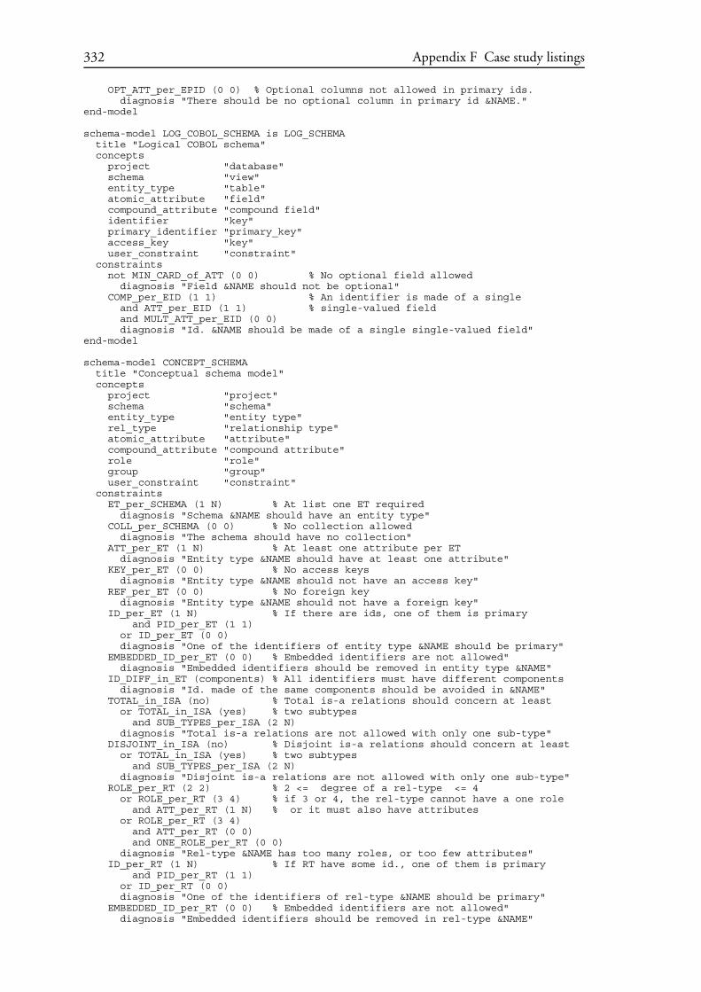
Appendix F Appendix F Appendix F Appendix F Case study listingsCase study listingsCase study listingsCase study listings 321321321321
F.1. The first case study: a forward engineering method 321
xiii
F.2. The first case study: the interview report 327
F.3. The first case study: the script of actions performed by the engineer 327
F.4. The second case study: a reverse engineering method 330
F.5. The Order.cob program analysed in the second case study 339
F.6. A small C program to clean log files 343
xiv
Glossary
This glossary is a list of the main terms used in this thesis. They are fully defined in thethesis. These definitions are summarised here for reference, as a reminder for the reader.
actoractoractoractor: An actor is a person, or a machine, that can perform actions and conduct processes.
automaticautomaticautomaticautomatic primitiveprimitiveprimitiveprimitive processprocessprocessprocess typetypetypetype: A primitive process type that can be performed by theCASE environment without the intervention of an engineer.
decisiondecisiondecisiondecision: A decision is either a choice of one or several product versions to abandon amongseveral ones, or a yes or no answer to a question imposed by the method.
engineeringengineeringengineeringengineering processprocessprocessprocess: An engineering process is a goal-driven process, i.e. a process thattries to make its output products comply with specific design requirements.
GERGERGERGER: The Generic Entity-Relationship model used as the basis for defining databaseschema models within the DB-MAIN CASE environment and the MDL language.
historyhistoryhistoryhistory: A history is the recording of everything that happens during the life cycle of anengineering project. It also includes all the products that are used or produced during theproject, as well as all the rationales according to which the processes are carried out.
hypothesishypothesishypothesishypothesis: An hypothesis is a statement that confines a problem to a particular context inorder to solve it.
loglogloglog filefilefilefile: A log file is an ASCII-based text file containing the trace of performed actions. Inthis thesis, log files are used to store primitive process histories.
manualmanualmanualmanual primitiveprimitiveprimitiveprimitive processprocessprocessprocess typetypetypetype: A primitive process that must be performed by a humanbeing, using the tools provided by the CASE environment.
MDLMDLMDLMDL: The Method Definition Language is a non-deterministic procedural language aimedat defining database engineering method in order to configure a CASE environment.
methodmethodmethodmethod: A method is a way-of-working commonly agreed among engineers to perform agiven work.
methodologicalmethodologicalmethodologicalmethodological engineengineengineengine: The methodological engine is a piece of program which is addedto a CASE environment in order for it to be able to follow a defined method.
methodologymethodologymethodologymethodology: A methodology is a system of methods and principles for doing something1,database engineering in this thesis.
method-freemethod-freemethod-freemethod-free projectprojectprojectproject: A project performed without the guidance of a declared method.The engineer may follow an implicit method anyway.
method-supportedmethod-supportedmethod-supportedmethod-supported projectprojectprojectproject: A project performed according to a method defined with theMDL language.
1 This definition is from [COLLINS,95].
xv
primitiveprimitiveprimitiveprimitive processprocessprocessprocess: A primitive process is an atomic process, that is to say, a process thatcomprises a single operation. It is a single step on the path towards the goals of an engi-neering process.
processprocessprocessprocess: A process is an activity that is carried out by an actor in order to transform prod-ucts.
processprocessprocessprocess typetypetypetype: A process type describes the general properties of a class of processes thathave the same purpose, and that use, update or generate products of the same types.
productproductproductproduct: A product is a document used, modified or produced during the design life cycleof an information system. They are database schemas and database-related texts.
productproductproductproduct modelmodelmodelmodel: A model defines a general class of products by stating the basic compo-nents they are allowed to be included and the assembly constraints that must be satisfied.
productproductproductproduct typetypetypetype: A product type describes a class of products that play a definite role in thesystem life cycle. A product type is expressed into a product model. A product is aninstance of a product type.
productproductproductproduct versionversionversionversion: A version of a product is the result of solving a problem in a particularcontext after specifying an hypothesis. Several hypotheses may lead to several versions of aproduct.
schemaschemaschemaschema: Database schemas can be any data structure description that can be of interest dur-ing the whole life cycle of the database engineering project, in any phase, at every abstrac-tion level, ranging from conceptual entity-relationship, object oriented or UML schemas,to physical Oracle or COBOL schemas.
strategystrategystrategystrategy: The strategy of an engineering process type specifies how any process of this typemust be, or can be, carried out in order to solve the problems it is intended to, and to makeit produce output products that meet its requirements. In particular, a strategy mentionswhat processes, in what order, are to be carried out, and following what reasoning.
texttexttexttext: A text is any relevant character-based document that is not a schema. This conceptencompasses program source files, SQL-DDL scripts, help files, word processing files,forms, etc.
tooltooltooltool: A tool is a function of the CASE environment that can be used through the menus,the toolbars, keyboard shortcuts, or with the mouse when it points to a window.
toolboxtoolboxtoolboxtoolbox: A toolbox is a collection of tools provided by the CASE environment. A toolboxcan be put at the engineer’s disposal by the CASE environment when required by themethod.
Chapter 1
Introduction
This chapter introduces the concept of process modelling. Then it draws astate of the art in the field. It lists a large series of research projects andclassifies them according to several criteria which draw the mainorientation of this thesis. The concept of process modelling in the largewill then be restricted to the database realm, and to the DB-MAINenvironment in particular for prototyping.
1.1. Process modelling presentation 2
1.1. Process modelling presentationEvery day, every living being performs a series of processes. Some of these processes areinnate, such as breathing. Most must be learned though. Some processes are learned earlyin the life, naturally, without help, because they are vital, such as walking. All beings of thesame species generally agree on the way of performing the process. More complex and lessvital processes are learned by everybody. Talking is such a process for human beings. But allmen and women do not speak the same language, some even communicate with hands. Inthis case, some references (specialist, book,...) detailing the way of performing the proc-esses, or simply tips, can be useful. This is why most widespread languages have dictionar-ies. Finally, there are much more complex processes which are only practised by restrictedgroups only, like a specific kind of job. Each job can even have some specialities. In thesecases, learning the process can be very long and the path can be littered with pitfallsbecause the way of working can be complex and various minds may apprehend it differ-ently. In fact, we should write “ways of working”, plural form, because each specialist canhave his or her own one. In some cases, two specialists who should do the same work maydo it differently enough for them to not understand each other during a discussion. Forinstance, two programmers can write applications that are compliant with the samerequirements, that do the same things, but one writes the application in C++, while theother one writes it in Prolog.
The good health of a large company is based on three fundamental resources: money, peo-ple, and information. Money is necessary to pay people, to buy supplies, for buildings,heating, communications,... People are necessary to do the job. And information is neces-sary to manage people, to manage stocks, to manage customers, to manage suppliers, tomanage production,... The lack of one of these three resources will inevitably lead to bank-rupt the company. Managing these three resources are three different jobs that all need tobe performed by specialists. Nowadays, for competitiveness reasons, information manage-ment must be supported by an information system. Since flaws in this information systemcan produce incorrect information, or no more information at all, the flaws can lead tobankruptcy. Furthermore, the information system has to evolve with the company andwith the company environment (laws, markets, company size, users’ wishes,...) in order tobe trustworthy all along the company life. So the information system design is a vital proc-ess, as well as its maintenance and its evolution, so important that it cannot be performedby a single man or woman, but rather by teams. To do their job correctly, all these peopleneed to understand each others, and to work in the same way. That is why, a few decadesago, some people tried to define good methods that would be followed by everybody. Mer-ise is such a method example among many others. But if such general methods can be goodstarting points, they hardly suit the needs of companies that have specific problems. That iswhy researchers all over the world have been working on designing tools to help companiesto model ways of working which are relevant to them, and to help these companies tomake their ways of working available to their people and accepted by them.
Computers evolve, applications evolve, new information arrive and must be stored everyday, but the archives, the memory of the company, do not evolve. Data stored in the infor-mation system have to survive to all changes in the computers or in the applications. Datahave to survive during a very long time, possibly the whole life of the company. In otherwords, the databases around which an information system is build is a basic asset that mustbe handled as such. This is why we will concentrate, in this thesis on modelling the proc-esses that can be performed by engineers who are in charge of designing, maintaining andmaking databases evolve.
Since a large database design activity has to be performed by several persons, it is importantfor them to share their knowledge. Since a database may have to survive during several dec-
1.1. Process modelling presentation 3
ades, engineers who designed it at the beginning will probably retire before its death. Sothe engineers who maintain the database are not the same. It is thus very important that allthe knowledge elaborated by the previous engineers be transmitted to their successors. Forthat reason, a good recording of all activities, all decisions taken, and all rationales that jus-tify the decisions must be recorded in a reusable way. In other words, the complete historyof the database design, maintenance and evolution must be kept.
In this thesis we will examine one particular way of seeing the modelling of database engi-neering processes and the recording of histories.
1.2. State of the art and related worksProcess modelling is a rather general subject for which a lot of research have been con-ducted for several decades. The first researches recognised the necessity of well definedmethods and models.
1.2.1. History of data and process engineering
Some first ways of structuring and representing data were introduced in the late sixties andin the seventies. For instance, [BACHMAN,69] gave birth to the entity-relationship (ER)model, and [CHEN,76] popularised this model. It then evolved to better suit the usersneeds, like [FOUCAUT,78] who adds the processing and their operational dynamics withthe REMORA project, and [HAINAUT,89] who extended it in order to cover a broaderrange of data models. More recently, [OMG,01] presents the last release in date of theUML model, a graphical communication model for representing all the aspects of an appli-cation design, including the static (ER-like schemas) and dynamic aspects of data struc-tures, as well as use cases and packaging.
Meanwhile, researchers noticed that software was becoming more and more unstable whilebecoming larger and more complex [DIJKSTRA,68]. So these researchers began to modelways of developing reliable software. This included researches on programming languages:structured programming with, among others, the birth of the ALGOL 58,60,68 language[DIJKSTRA,62], and the Pascal language [JENSEN,78], object oriented languages such asSIMULA 67 [DAHL,67], logical programming with languages such as Lisp [MCCAR-THY,60][STEELE,90], or Prolog [CLOCKSIN,84]. It also included researches on theways of designing software independently of the final programming language, that is to sayways to specify formally the different parts of the programs: The Jackson Structured Pro-gramming (JSP) [MCLEOD] is a method for modelling programs “in the small”, whichare programs manageable by a single programmer; the Jackson Structured Development(JSD) [MCLEOD] is aimed at larger projects; the waterfall model [ROYCE,70], the spiralmodel [BOEHM,88] and the fountain model [HENDERSON,90] are also well-knownsoftware engineering methods. [FICKAS,85] implements software automatically with atransformational development. More recently, researchers have explored ways to developnew software by reusing pre-existing software chunks [BENGHEZALA,01] instead ofredesigning everything every time. A less technical, more human-oriented approach ofimproving software is proposed in XP programming [XP] which focus on team work andcommunication inside the team.
Other people also began to model other aspects of information systems engineering, suchas the requirements in [SORENSON,88], [CHUNG,91], [ROLLAND,93], [DUBOIS,94] or [POHL,96], or the human-machine interfaces [BODART,95], [VANDER-DONCKT,97].
People then noticed that simply designing clean software does not solve entirely the prob-lem of instability because the software has to be maintained and to evolve. These activities
1.2. State of the art and related works 4
deserve great care too. All the rationales behind the changes have to be stored correctly inorder to not redo the same errors several times along the whole life of the applications[HAUMER,99]. In particular, since the information systems are build on top of a databasesystem, this one deserves great attention too [HICK,98].
Eventually comes a time when the applications, or simply the hardware onto which theapplications are run, become obsolete. It is then necessary to build new applications. Butthe content of the database, which is the memory without which the organisation cannotlive, has to be kept. It is thus necessary to re-engineer the databases, as presented in[HAINAUT,95] and [HAINAUT,96a].
1.2.2. Process modelling in the large
For such activities as requirements engineering, human-machine interface design, mainte-nance and evolution, re-engineering, as well as for forthcoming activities, the software pro-cess models defined previously are not adapted. Furthermore, those methods also proved tobe poorly adapted to the particular needs of each organisation, even for the jobs for whichthey were originally conceived. So a new trend is born: to give means to each organisationto define its own methods. [CURTIS,92] is a general paper which presents various aspectsof process modelling in the large, including business process modelling and software proc-ess modelling. [FEILER,93] and [JAMART,94] define various terms commonly used inthe process modelling domain. [KRASNER,92] shows the usefulness of process modellingwith a particular case study. Along the years, several research labs published various projectresults. [FINKELSTEIN,94] and [GARG,96] present in details several process modellingprojects. Among these project and others, we can enumerate:
• HFSP [KATAYAMA,89]: a process-centred software engineering model with a mathe-matical functional representation of processes.
• APPL/A [SUTTON,90]: a process-centred software engineering model with a program-ming (extension of the Ada language) way of representing processes. It is implementedin the Arcadia environment [TAYLOR,88].
• MELMAC [DEITERS,90]: A process centred software engineering process modellingapproach using FUNSOFT nets (high level Petri nets).
• DAIDA [JARKE,92]: a knowledge-based process-centred environment for databaseapplications.
• TAME [OIVO,92]: a goal-oriented approach to software engineering with a rule-basedmechanism for constructing methods.
• KBMS [ZEROUAL,92]: a knowledge-based system for modelling software engineeringmethods with rule-based techniques.
• Marvel [BARGHOUTI,90][FINKELSTEIN,92]: a rule-based software engineeringenvironment centred on reuse.
• Process Weaver [FERNSTROM,93][CAPGEMINI,95]: a process-centred environmentfor managing team-based activities with a Petri-net-like representation of the processes.
• SPADE [BANDINELLI,93]: a software engineering environment with an object-ori-ented process model based on Petri nets (using the SLANG language).
• TAP [YONESAKI,93]: the Task-Agent-Products approach is a process-centred environ-ment for software process modelling with agents and Petri-net representation of themethods.
• EPOS [CONRADI,93][CONRADI,94b][EPOS,95]: A process centred approach fordefining software engineering process models with an object-oriented specification lan-
1.2. State of the art and related works 5
guage (SPELL).
• Merlin [JUNKERMANN,94]: a process-centred software development environmentwith a Prolog-like process representation.
• SOCCA [ENGELS,94]: a process-centred software engineering environment withobject-oriented and data flow diagram representation of the processes.
• Adele [BELKHATIR,94][ESTUBLIER,94]: a process-centred software engineeringmodelling environment with object-oriented and trigger representation of the processes.
• Sentinel+Latin [CUGOLA,95]: a process-centred software engineering environment(Sentinel) with a rule-based temporal constraint language (Latin) to represent processes.
• MCASE [BRUNO,95]: a process-centred software engineering environment with dataflow based processes.
• Metaview [SORENSON,88][FROEHLICH,95]: a process-centred software engineer-ing environment with a rule-based description of processes.
• MetaEdit+/GOPPR [KELLY,96]: MetaEdit+ is both a CASE and a CAME (computeraided method engineering) environment; the method engineering part is process-cen-tred and uses a graph and object oriented representation of the processes (GOPPR).
• Nature, Crews [NATURE,96][ROLLAND,97][TAWBI,99]: context-and-decision-ori-ented meta-models for defining requirements engineering processes with a rule-basedrepresentation of processes. It is implemented in the Mentor CARE (Computer-AidedRequirement Engineering) environment [SISAID,96].
• APEL [DAMI,97]: a graphical (using data flow, control flow and state transition graphs)representation of software engineering processes.
• E3 [JACCHERI,98]: An object-oriented language with graphical representation for pro-cess-centred software engineering.
• Prime [POHL,99]: A process-centred environment for requirements engineering whichuses the process representation of Nature and extends it to allow the use of third partytools.
• PROSYT [CUGOLA,99]: A process-centred distributed business process modelling toolusing an artifact-based approach which allows deviations in enactment.
• [DITTRICH,00] presents a roadmap to using database technology for software engi-neering.
[MARTTIIN,98] and [SAEKI,94] are also nice papers that complete the list above withmany other projects. [TOLVANEN,98] presents method engineering approaches in itsthird chapter too.
A lot of the tools above allow the interoperability of several third party tools (editor, com-piler,...). More recent works [ESTUBLIER,96] [DAMI,97] [KELLY,96] [POHL,99] gofurther by investigating ways to make several process engines communicate with eachother, and/or with third party tools.
The use of process models has proved its usefulness in various other domains as well. Forexample:
• [BOGUSCH,99] shows the use of a process model for chemistry practices.
• [MUETZELFELDT,01] uses a process model for ecology activities.
One of the most widespread use of process modelling outside software engineering is cer-tainly business process modelling which is useful for three main purposes, namely Total
1.2. State of the art and related works 6
Quality Management, Business Process Reengineering, and Workflow Management:
• Catalysis [DSOUZA,98]: a graphical representation of business processes using UML.
• Artemis [CASTANO,99]: a business process reengineering environment.
• IDEF [DEWITTE,97]: a standard modelling and analysis method for business engi-neering.
• ProVision [PROFORMA,99]: an environment for business modelling and systemdesign.
• Other business modelling works include: [BARROS,97], [BRATAAS,97], [MAYER,98], [JORGENSEN,99], [GREEN,00], and [VONDRAK,01](workflow automation).
To summarise the previous enumeration of research project, six process modelling para-digms can be found in the literature:
1. Rule based: each process type is a set of rules. Some rules are preconditions that must befulfilled for the process to be enactable. Some rules are postconditions that are guaran-tied to be fulfilled when the process terminates. Other rules describe the behaviour ofthe process type (the equivalent of the strategy in our model). This model is one of themost widespread (DAIDA, TAME, KBMS, Marvel, Merlin, Sentinel+Latin, Metaview,Nature, Prime,...).
2. Functional: preconditions, postconditions and behaviour are all stated with mathemati-cal functions. This model is seldom used (HFSP for instance).
3. Petri nets: the strategy of process types are described with Petri nets, coloured Petri netsor any other variant of Petri nets. Also an often used technique (MELMAC, ProcessWeaver, SPADE, TAP among others).
4. Graph based: the strategy is represented with dataflow diagrams or state transitiongraphs. This technique is less used (MCASE, MetaEdit+ or APEL for example).
5. Procedural: the strategy is expressed in a procedural language. This is the technique wewill use in this thesis. It is also used by a few other research projects (such as APPL/A).
6. Object oriented: a variant of the procedural technique with the in fashion technique ofobject encapsulation (EPOS, SOCCA, Adele,E3,...).
The research projects can also be divided in two categories: process-centred and goal-ori-ented. Process centred techniques put the accent on the method itself, while goal-orientedtechniques stress their attention on the product that are to be produced and on the searchfor a way to reach that goal.
All the projects mentioned above present a way to describe a method and to use it. All ofthem also tell how to create such a method, but generally very briefly: the environmentintegrates a tool that provides this capability, nothing more. A few of them go further bygiving some methodological guidelines. [SCHLENOFF,96] presents some requirementsfor modelling processes, with the hope to define a general framework that would suit everyprocess modelling needs. [HUMPHREY,95] presents a way to make a process model(using the Personal Software Process model) evolve in the way of greater efficiency. [ROL-LAND,97] presents a complete framework for engineering methods for requirement engi-neering: a method is build like requirements, with a context-and-decision approach, possi-bly with the reuse of method chunks. [RALYTE,01a] and [RALYTE,01b] go further inthe same direction, focusing on the reuse of method chunks. Still further, [JORGENSEN,00a] shows how to define a particular process model by reuse of “general process models”and to harvest the latter with the knowledge gained by the use of the particular processmodel.
1.2. State of the art and related works 7
One of the main goals of all these researches is the quality of software. The SCOPE project[WELZEL,92] provides an assessment method to measure the quality of software designand generated products. But the quality of software also passes through the quality of theprocess model itself: [BROCKERS,93] verifies properties of a software process model,using FUNSOFT nets in the MELMAC environment; [SADIQ,00] proposes anothertechnique to analyse workflow based process models using graph reduction, in search ofdeadlocks and lack of synchronisation.
All the process modelling tools presented so far use their own representation of their data.[SCHLENOFF,00] presents the Process Specification Language (PSL) which is aimed atallowing the previous tools to exchange information.
A roadmap to the future of software engineering which identifies the principal researchchallenges is presented in [FINKELSTEIN,00].
1.2.3. CASE tools and meta-CASE tools
Software engineering, in particular database engineering, not only needs good methods tobe performed, but also good CASE tools. Concerning specifically database engineering,[ROSENTHAL,94] proposed a prototype CASE tool, DDEW, that can handle severaldatabase schema models using a unified underlying model called ER+ and transform aschema from one model to another using content-preserving schema transformations.[HAINAUT,94] and [ENGLEBERT,95] present another similar tool called DB-MAINwhich evolved towards a mature CASE tool [DB-MAIN,02a], while incorporating moreadvanced features, such as reverse engineering facilities [HENRARD,98]. This is the CASEtool that will be used in this thesis, and that will be extended with a methodologicalengine. A more general software engineering CASE tool, which already supports methodspecification, namely Phedias, is presented in [WANG,95]. This tool is in fact a meta-CASE tool (called a CASE shell in the paper): it is general enough to be used in varioussituations, and it needs to be customised in order to be usable as a CASE tool for specificneeds. Prime [POHL,99] (see above) is another metaCASE tool which is requirement engi-neering oriented.
1.2.4. History recording
The use of a CASE tool or of a metaCASE tool can help a software (or database) engineernot only to perform a particular job. If the analyst has to perform a second or a third job ofthe same kind, he or she can simply follow the same way of working. But it appears clearlythat learning the lessons from the first job can improve the quality and the efficiency of thesubsequent jobs. The best way recognised by the research community to learn the lessonsof a job is to keep a whole trace of it, and to record all the rationales behind all the deci-sions taken by the analyst. It allows engineers to be reminded, during subsequent projects,how the discussion was conducted and why the final decision was taken as such; it allowsengineers to take future decisions much faster, and in concordance with the first one. Eventhe first application, result of the first engineering job, may have to evolve. It is even moreimportant in this case to remind exactly what was done the first time and why it was donethat way. The matter of recording rationales is discussed in [POTTS,88]. Later on, severalresearchers followed the idea. [SOUQUIERES,93] presents a requirement engineeringframework in which all the decisions and their rationales are perfectly documented.[POHL,97] and [DOMGES,98] note that traces of genuine engineering projects can bevery huge and time consuming, and propose a way to capture the needed information only,which may vary according to the projects specific needs. In [HAUMER,99], the traces ofthe original engineering of a system are accompanied with traces of concrete system usagescenarios in order to make the information even more pertinent when making the systemevolve. [ZAMFIROIU,98] (also [ZAMFIROIU,01]) studies software engineering traces
1.2. State of the art and related works 8
independently of any CASE tool. This work has three objectives: recording traces (possiblywith version management), synthesise them into operation flow (to enhance readabilityand usability), and a measure of the continuity of the flow (in order to detect subsequentchanges, to evaluate the impact on the project, and possibly to assist the engineer in repair-ing breaks). This work proposes a trace model (KARMA), as well as tools to handle and toquery traces.
Since the purpose of this thesis is to help database engineers perform their job, it is animportant issue to produce usable tools. Lessons can be learned from [CATARCI,00]which relates the story of a database research team who already had to deal with similarproblems of user acceptance of specific tools it designed.
1.3. Database specificsA lot of process modelling projects were already conducted all over the world, as shownpreviously. They concern a very broad range of application domain: software engineering,requirements engineering, business processes, electrical engineering, ecology,... Within theframework of this thesis, we will concentrate on the database realm. Indeed, in a largeorganisation, the management of employees, customers, products, finances and otherresources is nowadays always performed with one or several large information systems. Allthese information systems are a set of applications using a central database which containall the memory of the organisation. Along the time, the applications evolve, sometimesrather deeply, and can even be completely replaced several times along the life of theorganisation. The database management system may also evolve. But the data stored in thedatabase are one of the main resources of the organisation and must be kept in perfect statewithout any loss along the whole life cycle of the organisation, even if their format andstructure evolve. So databases really deserve a particular attention in their treatment.
Since so many projects were already conducted and since so many (meta)CASE toolsalready exist, one should wonder why we do not use one of these tools. The answer holdsin two main points. Firstly, this thesis is conducted in the framework of the DB-MAINproject, so one prerequisite is to use the DB-MAIN CASE tool (see Section 1.6), either bydeveloping new functions in it, or by integrating it with other tools. Secondly, the databaserealm has several specific aspects that cannot be handled by non-database-specific CASEtools:
• Database engineering theory is much more advanced than software engineering theory.Indeed, the transformation of a database schema compliant with one model to anothersemantically equivalent schema compliant with another model (for instance, the trans-formation of an ER schema into a relational schema) can be described very preciselywith a series of semantics preserving elementary transformations that are all publishedand proved to be correct [HAINAUT,96c]. In the design of a program, the gap betweenthe requirements and the code is much larger. Some formal requirements expressed withformal languages can be translated into source code of functional or logical languages,but seldom in much more popular procedural source code. And non-functional require-ments expressed with the natural language have a semantic that cannot be grasped bymachines. Nothing more than analysis tools (for instance searching, pattern matchingand program slicing tools), prototyping tools, and simple text editors can help the pro-grammers, not even to prove that the result is the one expected. In other words, mostdatabase engineering works can be performed through a set of dedicated elementarytools which do not exist within other disciplines. The need to take into account the par-ticularities of the actors needs is underlined in [NUSEIBEH,93].
• As a corollary of the first point, in most disciplines a text (a source file, a requirementdescription, a scenario of a task,...) is often the smallest elementary concept that can be
1.3. Database specifics 9
handled by tools: a text can be edited, a source file compiled,... Within the databaseengineering paradigm, a database schema can be decomposed in all its components andtransformations applied to some specific components directly. So a CASE tool that sup-ports database engineering activities has to be able to handle a fine-grained decomposi-tion of the products, which is seldom the case with other CASE tools.
• Elementary tools used in database engineering activities are often simpler than in soft-ware engineering. Indeed, schema editing functions are often simpler to implementthan a compiler or a debugger. As a consequence, a software engineering CASE tool sel-dom offers all the tools which are necessary to perform a complete project, it oftenrequires third party tools (such as an advanced text editor, a compiler,...). A databaseengineering CASE tool can more easily integrate all the necessary tools or provide meansto easily add them (such as an advanced macro language or a 4GL like the Voyager lan-guage included within the DB-MAIN CASE tool, as presented in Section 1.6). Hencedatabase engineering allows a better integration of tools.
The fact that database engineering is the target of this thesis does not mean that the modeland the language developed in this work must be confined to databases. Indeed, only a fewupdates to the model should be necessary to extend it to other domains of interest. Theseextensions will be presented in chapter 14. In a way, [DOWSON,94] summarises the con-tent of Chapters 3, 4, 5, 6, 7, 9, 13 applied to software engineering.
1.4. GoalsThis thesis will pursue one main goal which is to bring the most useful possible help todatabase engineers. This goal has to be seen with various angles according to the differentaspects of the database engineer’s job:
• The way of working he or she should follow can be imposed to him or her, strongly orloosely. And he or she can be guided to correctly follow this path.
• The job the database engineer actually performs can be recorded. The fact that databaseengineering tools can be integrated can make the recorded history very useful for varioustasks. This usability will be proved by proposing a structure for history recording andproviding a series of operators to handle this structure.
A lot of research projects, some of them presented in Section 1.2, already tackled the guid-ing problem. Most of them use either a declarative language, an object-oriented language,or Petri net-like representations to define a method. Only a few projects use a functionalmodel (HFSP for example) or a more traditional procedural language (APPL/A forinstance).
About programming languages, it often appears that declarative languages, functional lan-guages and Petri-net like representations are stuck in universities or research laboratories,and are poorly adopted by industrials. Object oriented programming languages have a bet-ter acceptance in the industrial world, but are often badly used, with a few objects encapsu-lating large chunks of procedural code. Procedural languages are still the most widespreadlanguages.
Of course, as [OSTERWEIL,97] underlines, “Software Processes are Software too” is a falseassumption. So the choice of a programming paradigm cannot be extended to processmodelling as easily. According to [BOBILLIER,99], activities such as requirements engi-neering, which is more decision centric and which has to deal with non-functional require-ments, are mental activities. Indeed, the problem is loosely and badly defined from thebeginning and must be refined while solving it. It seems that declarative languages are bet-ter suited for modelling such processes. But database problems are different. Indeed, along
1.4. Goals 10
the advancement of the project, the work is more and more technical, more and moretransformation oriented. When a design project begins, the database engineer receiverequirements which were already specified during a previous requirements engineering pro-ject, and he or she draws a first conceptual schema using a graphical editor. Then he or shegoes forward by normalising the schema or optimising it, possibly integrating several sche-mas. These operations can already be performed using some transformations, but somedecisions still need to be taken to apply the transformations correctly. In a later step, theschema is transformed more automatically in order to produce the logical schema, thephysical schema, and finally to generate the code. A reverse engineering job begins withlegacy programs and data which are in use for a long time. The jobs mainly consist in ana-lysing and transforming these sources. So these job are more technical ones, more transfor-mation oriented. That is why this thesis supports the idea that a procedural language withan algorithmic graphical representation of a method is the way of working that should bepreferred for this kind of database engineering activities. Advantages and disadvantages ofthe different paradigms will be discussed and it will be proved that this choice naturallyleads to a real help for the database engineers.
This thesis does not only define one more framework and one more method descriptionlanguage to the research community, but it shows its usefulness with the implementationof the language and of a methodological engine in a CASE tool of professional quality.This implementation does not simply show the feasibility of the theory presented in thefirst chapter of the thesis, but it also shows that the technique is industrially viable,although industrial users still need to be converted to it for a wider use.
1.5. Structure of the thesisIn this introduction, process modelling was described informally, related works and thestate of the art in this domain were examined in the large. Then the specificity of the data-base realm was shown, the remaining of this thesis being concentrated in it. When theframework was drawn, the goals of this work were stated. This chapter will be terminatedby a short description of the DB-MAIN CASE tool, which is the concrete framework forthe evaluation of the results of this work.
In the three following chapters, all the concepts and components that are necessary formodelling database engineering processes are precisely defined: Chapter 2 gives a definitionof all the concepts, Chapter 3 gives a complete description of product models and producttypes, and Chapter 4 is about the description of process types. A language (MDL) for cod-ing all these concepts is defined in Chapter 5.
Chapter 6 is devoted to a full description of histories and Chapter 7 to their handling andtransformation.
The MDL language is procedural but aimed at being executed by human being rather thanby machines. Since human beings and machines act differently, a few methodologicalguidelines deserve to be followed to correctly define a method. Chapter 8 is devoted tothese methodological aspects.
Chapters 9, 10 and 11 address experimentation. Chapter 9 studies the human-machineinterface aspects, while Chapter 10 is devoted to the internal architecture. Chapter 11 pres-ents two case studies. Chapter 12 presents a few real projects using the implementation.
Chapter 13 underlines an important aspect of methods which is not taken into accountpreviously but which deserves a full attention (maybe another thesis): the problem of themethod evolution. Chapter 14 traces paths for future works and concludes this work.
1.6. DB-MAIN 11
1.6. DB-MAINDB-MAIN is a database oriented CASE environment developed at the university ofNamur, in the Database Engineering Laboratory (LIBD2). The purpose of this CASE envi-ronment is to assist a database engineer in every database engineering activity he or she canface, including database design, database reverse engineering, database evolution, databasere-engineering, databases integration,... In this section, we will describe its main character-istics.
• It is based on the GER model presented in Chapter 3 which is general enough to allowa database engineer to represent a very broad range of concepts from a very broad rangeof data models at all abstraction levels.
• It is transformation-based. A database schema which is compliant with a given schemamodel can be transformed into a semantically equivalent schema which is compliantwith another schema model. This transformation can be performed step by step with aset of basic transformations by the analyst who can control the whole process andunderstand what happens. This is rather different from most commercial CASE envi-ronments where schema conversion from one model to another is just a black box.
• It allows different usage levels. Schema transformations can be performed in severalways; step by step with full control by the engineer, in an automated way with anadvanced configurable assistant, in an automated way with a simple assistant working ona problem-solution basis, or as a fully automated black box.
• It is methodology neutral. An engineer using this CASE environment is allowed to dowhatever he or she wants. He or she can either follow a well-known method, or his orher own method, or simply use the CASE environment as a white board on which he orshe can draw freely. It is this aspect of the CASE environment that is addressed through-out this thesis.
• Users can personalise the GER model by defining new meta-properties for its differentconcepts. For example, it is possible to add an owner meta-property to the entity typeconcept, so that the owners of each entity type can be specified.
• It embeds a 4GL (namely Voyager 2, [ENGLEBERT,99]) which allows database engi-neers to develop their own schema transformations, or more complex tools such asreport generators or specific DBMS DDL generators.
• It allows data structure extraction and data structure generation for several DBMS andcomputer languages. Some of the generators and extractors are written in the Voyager 2language and their sources are provided to allow engineers to adapt them to their ownneeds.
• It is repository-based. All the schemas and other texts are kept in a built-in object ori-ented repository. The structure of this repository is described in the manuals [ENGLE-BERT,99]. The repository is accessible through the Voyager 2 language, and throughC++ and Java classes.
The theoretical aspects of this thesis will be implemented in the DB-MAIN CASE environ-ment for evaluation. The repository will be extended to store the new concepts we willdefine in Chapter 2. And the user interface will have to be updated in order to help theengineers to use all the new capabilities.
A more comprehensive description of the CASE tool can be found in [ENGLEBERT,95]and in [DB-MAIN,02A].
2 Laboratoire d’Ingénierie de Bases de Données
Part 1Part 1Part 1Part 1
Models andModels andModels andModels and
MethodsMethodsMethodsMethods
Chapter 2
Basics
This chapter defines the building blocks that will be used throughout thisthesis. Firstly, it defines the basic concepts and terms on which we willbuild our proposal: actor, analyst, database engineer, method engineer,process, engineering process, primitive process, process type, strategy,toolbox, product, schema, text, product type, product model, hypothesis,decision, product version,... Secondly, the basic concepts will beassembled in a three level engineering process model that will guide us allalong this thesis like a map.
2.1. Basic definitions 16
2.1. Basic definitionsThis thesis aims to develop concepts, models and tools to help software engineers in theirdatabase design projects. The processes we are considering are perceived as product trans-formation activities. It is thus necessary to begin by defining more precisely the kind ofproducts we are talking about, as well as the transformation processes, and who will have todo every job.
• Actors
An actoractoractoractor is a person, or a machine, that can perform actions and conduct processes. Ahuman actor is an intelligent being capable of thinking and taking decisions. He or she canlook for a non-predefined solution when facing a new problem. Human actors can also getslow and lazy when facing repetitive and tedious works. Machines can only apply pre-defined recipes, but they can do it quickly and without getting tired. In this thesis, we willdevelop principles about transformation processes, from their design to their use. So we candefine two main classes of actors:
• The first class is made up of the people who design the transformation processes. Theyare human beings only, because their job is mainly based on decision taking andrequires database engineering technical knowledge, as well as a good knowledge of theorganisation and the people working for it. We will call them the methodmethodmethodmethod engineersengineersengineersengineers.They decide how the actors of the second class have to work, and how they will behelped.
• The second class comprises the people and computer programs who will apply themethods as a series of transformation processes. We will call the people databasedatabasedatabasedatabase engiengiengiengi----neersneersneersneers, analystsanalystsanalystsanalysts, or simply usersusersusersusers. We will call the computer programs functionfunctionfunctionfunction, proceproceproceproce----duredureduredure, operationoperationoperationoperation or assistantassistantassistantassistant depending on the context.
Though we will be interested in the distinction between human actors and machines, wewill not address some important project management problems, such as human resourcemanagement (studying dependencies between people and machines, affecting particularpersons to particular tasks,...) which is a complex problem studied in [SUTCLIFFE,00]. Inparticular, actors modelling will be ignored in this thesis.
• Products
A productproductproductproduct is a document used, modified or produced during the design life cycle of aninformation system. As we focus specifically on database engineering, we will describemainly database schemasschemasschemasschemas and database-related textstextstextstexts. Database schemas can be any datastructure description that can be of interest during the whole life cycle of the database engi-neering project, in any phase, at every abstraction level, ranging from conceptual entity-relationship, object oriented or UML schemas, to physical Oracle or COBOL schemas. Weexamine this in more detail in Chapter 3. A text is any relevant character-based documentthat is not a schema. This concept encompasses program source files, SQL-DDL scripts,help files, word processing files, forms, etc.
• Processes
A processprocessprocessprocess is an activity that is carried out by an actor in order to transform products. Agoal-driven process, i.e. a process that tries to make its output products comply with specificdesign requirements [MYLOPOULOS,92], will be called an engineeringengineeringengineeringengineering processprocessprocessprocess. Mostgenerally, a process is made up of a series of operations, that are processes. Atomic proc-esses, that is to say, processes that comprise a single operation, are called primitiveprimitiveprimitiveprimitive procprocprocproc----essesessesessesesses. A primitive process is simple enough to be considered basic. It can be performedautomatically using the correct tool. A primitive process is a single step on the path towardsthe goals of an engineering process. For instance, producing the SQL-DDL script of a data-
2.1. Basic definitions 17
base is an engineering process. During this process, defining the type and length of a singlecolumn is a primitive process.
• Histories
For several reasons developed in Chapter 6, it is interesting to store a trace of every opera-tion performed during each process. A historyhistoryhistoryhistory is the recording of everything that happensduring the life cycle of an engineering project. We will see later on that this trace needs tobe readable, formal, correct and complete. The history also includes all the products thatare used or produced during the whole project. Finally, all the rationales according towhich the processes have been carried out are part of the history too.
• Methods
When a process is performed, it follows a predefined commonly agreed upon way of work-ing, called a methodmethodmethodmethod. From the seventies to the beginning of the nineties, a lot of methodwere developed (Merise [COLLONGUES,89] for instance) and published in the literature.More and more companies tried to adopt such methods, but a predefined method is gener-ally perceived academic and not well adapted to the industrial world that often requirescustomised methods. To adapt a company way-of-working, or culture, to a particularmethod generally leads to failure. It is much better to attempt to adapt the method to thespecific needs of the company. This thesis will show how one can define or adapt a custom-ised method. To define a method, we have to precisely define the properties of two catego-ries of components: its products and its processes. More precisely, we will define a methodby an arrangement of product types and process types.
• Product type
A productproductproductproduct typetypetypetype describes a class of products that play a definite role in the system lifecycle. A product is an instance of a product type. For example, the Library Personnel Inter-view Reports is a product type. Every single interview report is an instance of this type.
• Process type
A processprocessprocessprocess typetypetypetype will describe the general properties of a class of processes that have the samepurpose, and that use, update or generate products of the same types. These general prop-erties will have to include the list of product types to transform and the list of expectedresulting product types, as well as a strategy to follow. A process is an instance of a processtype. Engineering processes will be described by engineeringengineeringengineeringengineering processprocessprocessprocess types,types,types,types, and primitiveprocesses will be described by primitiveprimitiveprimitiveprimitive processprocessprocessprocess typestypestypestypes. For instance, the SQL-DLL codeproduction for the library management database design is an instance of the general SQLScript Design engineering process type which tells what type of product have to be gener-ated and how. The specification of each column data type is an instance of the ColumnData Type Definition primitive process type which proposes a list of valid data types.
• Process strategies
The strategystrategystrategystrategy of an engineering process type specifies how any process of this type must be,or can be, carried out in order to solve the problems it is intended to, and to make it pro-duce output products that meet its requirements. In particular, a strategy mentions whatprocesses, in what order, are to be carried out, and following what reasoning. For example,the strategy for our SQL Script Design process can state that the database engineer must(1) create the database itself, (2) create all the tables, (3) declare all the columns in everytable, (4) specify each column’s data type, (5) declare primary identifiers, (6) declare for-eign keys and (7) declare other constraints.
Primitive process types are basic types of operations that will be performed by the analyst,or by a CASE tool. They have no associated strategy. They can be classified into four cate-gories according to the level of automation and user involvement:
2.1. Basic definitions 18
1. BasicBasicBasicBasic automaticautomaticautomaticautomatic processprocessprocessprocess typestypestypestypes. Such a process is context-free and does not require anyparameters nor configuration settings. The new entry in the file menu of any applicationis such a process type.
2. ConfigurableConfigurableConfigurableConfigurable automaticautomaticautomaticautomatic processprocessprocessprocess typestypestypestypes. The effect of such a process depends on generalsettings defined at method definition time. It is specific to a definite design environ-ment and can be considered a part of the culture of the organisation. For example, thespelling checking facility of every word processor does its job automatically when theright dictionaries are installed.
3. UserUserUserUser configurableconfigurableconfigurableconfigurable automaticautomaticautomaticautomatic processprocessprocessprocess typestypestypestypes. These automatic processes need to be userconfigured before each activation. Process types that can still be executed automaticallybut which needs to be configured before each use, by the user himself or herself. Forinstance, each document photocopying session requires to manually set the correctnumber of copies, the contrast, the zoom factor, and the paper size before proceeding.
4. ManualManualManualManual processprocessprocessprocess typestypestypestypes. A manual process is carried out by the user, possibly with someancillary help from the tool. The interpretation of interview reports when drawing a rawconceptual schema is an example of such a process type. Most generally these processesencompasses the knowledge-based user activities that cannot be carried out by tools.However, in order to perform a manual process, the database engineer needs some basictools.
• Basic tools and toolboxes
A basicbasicbasicbasic tooltooltooltool is a primitive function of the supporting CASE tool. Tools can be grouped toform a toolboxtoolboxtoolboxtoolbox. To each process type of the fourth group, a toolbox is associated by themethod engineer. To perform a process of one of these types, the database engineer can useany tool from the associated toolbox. For instance, the drawing toolbox can contain a pen-cil, a ruler and an eraser.
• Product models
We have defined the notion of product type which allows us to define a class of productsthat plays a definite role in the current method. Two product types can appear in a methodthough their model can be the same. In the Conceptual Analysis process, for instance, sev-eral conceptual schema types can be identified: the partial raw conceptual sub-schemas, thenormalised conceptual sub-schemas, the integrated conceptual schema, the sub-systemviews, etc. All of them are made up of the same set of building blocks and assembly rules,namely some variant of the Entity-relationship model or of the UML class model (e.g.,through a conceptual profile). Hence the concept of productproductproductproduct modelmodelmodelmodel. A model defines a gen-eral class of products by stating the basic components they are allowed to be included andthe assembly constraints that must be satisfied. A product type is expressed into a productmodel. For instance, all the interview reports of the Library Personnel Interview Reportstype have to be written using the same Interview Report Form model which states thatinterview reports must have a date, references to the project, the interviewer, the inter-viewee, and a series of sections having a subject and the comments of the interviewee aboutthe subject.
• Hypotheses, versions and decisions
User configurable and Manual process types need some human interaction to be per-formed. This is generally due to the need for some intelligence or some knowledge thatsupporting tools do not have. But, even database engineers can lack knowledge, so thatthey may face a problem they cannot solve straight away with certainty. They have differ-ent ideas of solution they want to explore. Each idea is developed into a design branch,leading to a definite solution. These solutions can then be evaluated and compared, one ofthem generally being chosen as the best fitted. Each solution results from a restriction of
2.1. Basic definitions 19
the problem domain through hypotheseshypotheseshypotheseshypotheses. By stating different hypotheses, an engineer candefine several contexts and solve the problem in each of them. Each resulting product is infact a different versionversionversionversion of the final product. By comparing all these versions, an engineercan take the decisiondecisiondecisiondecision of keeping or rejecting each of them. The hypotheses, the productversions obtained from these hypotheses and the final decisions all have to be kept in thehistory. For example, an analyst trying to draw a conceptual schema on the basis of inter-view reports can have problems with the interpretation of some sentences. It is not clearwhether the keywords characterising a document of the library have to be stored separatelyor not. The analyst can make both hypotheses independently and solve the problem twice.When the job is finished two schemas versions are produced: “library/several keywords”and “library/one keyword line”. The analyst can see the interviewee again with both solu-tions printed on paper to discuss of the best choice, then store in the history the decision tokeep the “library/several keywords” version and the rationale of this decision: “These key-words will serve to search for the documents.” During the remaining of the project, theother version of the schema will no longer be used, but it is not discarded and is kept in thehistory.
Another kind of decisiondecisiondecisiondecision can be imposed by the strategy of a process type. This kind ofdecision can be necessary to decide of doing one action or another, or to decide how manytimes something has to be done, as it will be shown in Chapter 4.
2.2. ArchitectureThe concepts described in the previous section are shown in Figure 2.1, together with theirrelationships. This concept architecture comprises three levels, namely: the instance level,the type level and the model level.
Figure 2.1 The architecture
The instanceinstanceinstanceinstance levellevellevellevel contains the processes and the products used, generated and updated bythe processes. The level comprises the objects of the history. A process is either an engineer-ing process or a primitive process. The products are used, generated, or modified by theseprocesses. To be performed, some processes required that other processes be performed.
Inst
ance
of
required using (...)
is a
requires using (...) Generates
Product model Model level
Instance level Product
Updates
Uses
Is o
f
Process type Product type
Generates
Inst
ance
of
Updates
Uses
Type level
Process
2.2. Architecture 20
These sub-processes use or update some products given by the calling process. The sub-processes can also generate some products and give them back to the calling process. Thehypotheses formulated by an engineer are attached to the processes performed in the con-text they define. All the processes leading to different versions of a same product use thesame input products. These different product versions form a series of products of a sametype; they are given the same name with different version names. A decision to reject toproduct versions is a special kind of process: instead of generating or updating a product, itmerely designates products among a collection of input product (generally different versionsof a product). In standard terms, a decision “uses” the input products from which it willselect a subset. We consider that the process “updates” the selected products. A decisionimposed by the strategy of a process type is a special kind of process too, which only “uses“some products to evaluate an expression whose result determines what processes will beperformed later.
The typetypetypetype levellevellevellevel describes process types and product types that form a method. The descrip-tion of each process type comprises its interface and its strategy. The interface is made upof the types of the products that are used, updated or generated by the processes of thistype. Each process of the instance level is an instance of a process type. In the same way,each product is an instance of a product type. So, an integrity constraint of this architectureis that each product that is used, updated or generated by a process is an instance of a prod-uct type linked to the process type of which the process is an instance. This link must playthe same function (uses, updates or generates). The performance of a process of one typeoften requires that some processes of other types are performed using some products ofspecified types. This process type composition must be compliant with the process compo-sition at the instance level. A decision imposed by the strategy is itself a special kind ofprimitive process type that updates, or generates, no product type. Since a decision of keep-ing or rejecting some product versions is taken whenever at performance time, these deci-sions cannot be prescribed by the strategy, so they cannot appear at the type level.
Figure 2.2 shows the meta-model of the type level (using the ER model presented in Chap-ter 3). It shows that a product type is either a global product type (its instances can be usedby any process) or declared locally to a process type. It also shows that some of the localproduct types are the formal parameter of the process type. According to the “mode”attribute, these are the product types used, updated or generated by the process type in Fig-ure 2.1. When a process type requires that a process of another type is performed, someparameters are transmitted. These parameter are product types (either local product typesor global ones) which must match two by two with the formal parameters of the requiredprocess type.
Figure 2.2 The type level meta-model
1-10-N transmits
1-1
0-N
requires
1-1
0-N
required by
1-1
1-N
match
0-N
1-1
is-of 1-10-N declared in
Local product type Process type
Invocation
Formal parameter mode
Product type
Global product type
Actual parameter
2.2. Architecture 21
The modelmodelmodelmodel levellevellevellevel describes product models. Each product type is of a product model, i.e.,each product of that type, of that class, is built with components pertaining to its associatedproduct model and must be compliant with that model.
This architecture obviously is asymmetrical: there is no process model. Such a model couldhave been defined and certainly would be useful. It would allow a method engineer todefine, e.g., a Logical design process model which could be specialised into Relational logicaldesign or Object logical design process types. We think that the effort would not be justifiedby an increased productivity of the method engineer, at least in the database realm. There-fore, in the limited context of this thesis, we have left it for further research. [JAMART,94], [ROLLAND,95], [DOMINGUEZ,97] and [HARANI,98] present an architecturewith process models (called process meta-models) that allow the design of methods for vari-ous domains of activities, the process (meta-)model allowing to define the concepts(dependent on the domain of activities) that can be used by the process types.
The Figure 2.3 suggests an illustration of the this concept architecture. The C++ programsmodel is a text model that specifies the syntax of C++ program files. Main and GUI areparticular types of C++ files. The first type contains the core source files of an application,while GUI contains all the GUI-related source files of the same application. Manage-ment/2.0 is a particular C++ program source file that contains the main procedure of amanagement module. Management screen is a file including all the procedures required fordisplaying the management module main screen. In the same way, General Ledger and Per-sonnel are two instances of the Conceptual schema product type, which is expressed in theERA model product model.
In the same way, Figure 2.4 shows two process hierarchy examples. The C++ programdesign process type has a strategy that was followed by the Management GUI functionsdesign. General Ledger schema design and Personnel schema design are two conceptual schemadesigns performed with the same pattern described by the Conceptual schema design type.
Figure 2.5 shows an example of a very simple project combining the product and the proc-ess hierarchies, compliant with the architecture shown in Figure 2.1.
In this chapter, the notion of product model will be precisely detailed, aswell as a way to define some of them. The GER (generic entityrelationship schema) model will be presented as a reference schema model.It will be used to define particular database schema models by renamingits concepts and stating a series of constraints on these concepts. Textmodels will also be defined with a regular grammar. Finally, aninheritance mechanism to express product models as sub-models of otherproduct models will be developed.
3.1. Basic considerations 24
3.1. Basic considerationsAn in-depth analysis of several database engineering methods exhibits both strong similari-ties and many specific aspects. What makes them similar, among others, is that, at eachlevel of abstraction, they rely on some variant of popular specification models. However,instead of adopting such models as off-the-shelves components, most methods redefine andcustomise them according to the needs, culture and available technology of the businessenvironment. In some sense, there are as many ERA, NIAM and UML models as there areorganisations that use them. Product models are to be considered as a way to preciselydefine what is exactly intended by each model used by the organisation. In particular, theydefine the concepts, the names to denote them and the rules to be used to build any com-pliant product.
In the context of database engineering, we define two main kinds of models, namelyschema models and text models.
A schemaschemaschemaschema modelmodelmodelmodel allows designers to specify data/information structures. The ER modelproposed by Bachman in the late sixties, inspired by the pioneer DBMS IDS [BACH-MAN,69] and popularised by Chen [CHEN,76] is such a model. The general ER model(GER) developed in the LIBD3 and implemented in the DB-MAIN CASE tool is an exten-sion of the ER model. This wide-spectrum GER model is intended to describe data/infor-mation structures at different abstraction levels and according to the most popular para-digms [KIM,95] (Figure 3.1).
A personalised schema model will be defined as a specialisation of a the GER model. TheGER model will be described in detail in Section 3.2, and some tools to specialise it will bebuilt in Section 3.3.
Abstraction levels Representation paradigms
Conceptual ERA, Merise Merise-OO, Chen, NIAM, OMT, Booch,Fusion, UML, etc.
Logical Relational, network, hierarchical, standard files, OO, XMLSchema, etc.
A texttexttexttext modelmodelmodelmodel allows designers to specify every other kinds of information. Indeed, text filesappear in many forms ranging from computer language source files with a very strict syntaxto filled forms, and to natural language texts. Some of these text can be rapidly examined inorder to analyse their structure:
• A C++ source file is made up of function declarations. A function is prefixed by a headerand an opening curly bracket, it is made of statements, and it is terminated by a closingcurly bracket. A header is made of a name and parameters, the parameters being putbetween parentheses and separated by commas. A statement is made of keywords, vari-ables, constants and other symbols, and is terminated by a semi-colon. Keywords, func-tion names, variables, constants, punctuation marks and other symbols are all made ofcharacters which are classifiable in different sets: figures, letters, punctuation marks,mathematical symbols,...
3 LIBD: Laboratoire d’ingénierie de bases de données, database engineering laboratory, computer sciencedepartment, university of Namur.
3.1. Basic considerations 25
• An XML file is a text containing mark-ups and character data. A mark-up is a stringenclosed between angle brackets <...>, and character data are the strings not surround by< and >. An XML file is made up of elements. An element starts with a start tag which isa mark-up and ends with an end tag which is another mark-up whose content is pre-fixed by a slash /. An element has a name, which appears in both the start and the endtag, and possibly attributes, which can be given a value in the start tag. All the characterdata and elements between the start tag and the end tag is the content of the element.XML being a kind of text descriptor, the result of the interpretation of an XML file isitself a text file with any other syntax.
• A form is made of sections. A section has a title and is made of questions and answers. Aquestion and an answer are made of words, numbers or items, and punctuation marks.Items are made of words and numbers, and are prefixed by check marks. Words aremade of letters.
• A text written in natural language is made of paragraphs. A paragraph is made of wordsand punctuation marks. A word is made of letters.
There are obvious similarities among all these text variants. Their structures can bedescribed in a hierarchical way, each element being made of a sequence of sub-elements. Infact, all these texts are written according to a particular grammar. So, a text model can bedescribed by describing the grammar with which it complies. As described above, XMLitself could be used to describe the grammar of all the texts.
In most computing environments such as DOS-based or Windows-based, file names havean extension. This extension is content-based: it specifies the family of programs that areallowed to process the file. In other words, each file extension is associated with a particu-lar grammar and with the processors that understand it. For instance, the “RTF” extensionrefers to word processors that understand the RTF grammar (e.g., Star Office, Frame-Maker, MS Word, etc.)
Section 3.4 will show how a text model can be described by defining its grammar or simplyby giving a list of associated file extensions.
3.2. The GER modelThe GER model is a Generic Entity/Object-Relationship model that has been defined in[HAINAUT,89], and that has been implemented in the DB-MAIN repository. Its mostimportant components are presented in this section.
3.2.1. Schema
A schemaschemaschemaschema is a description of a collection of data or information structures. It is made up ofthe specification of entity types, relationship types, attributes, roles, is-a relations, process-ing units, collections and constraints. The full name of a schema comprises its name and itsversion. The schemas of a project have distinct full names. The graphical representation ofa schema is shown in Figure 3.2: TRANSPORT/Conceptual is the full name of a conceptualschema of a Transport management system. The name of the schema is “TRANSPORT”while its version is “Conceptual”.
Figure 3.2 A schema
TRANSPORT/Conceptual
3.2. The GER model 26
3.2.2. Entity types
An entityentityentityentity typetypetypetype is used to denote objects in two different contexts:
• It can be the representation of a concept of the real world: a person, an invoice, a vehi-cle,... Such an entity type should be characterised by some properties and links withother entity types.
• It can be a technical data structure which has the same syntactical needs.
Figure 3.3 shows an example of an entity type named PERSON. The top compartmentcontains the name. The second compartment contains some attributes that characterise theentity type. The third compartment contains various constraints. The bottom compart-ment contains some processing units applicable to the entity type. Only the first compart-ment is mandatory, while the others are independently optional. These attributes, con-straints and processing units are examined hereafter.
Figure 3.3 An example of entity type
3.2.3. Relationship types (rel-types)
A relationshiprelationshiprelationshiprelationship typetypetypetype, also called a relrelrelrel-typetypetypetype, is a link between two (binary rel-type) or more(n-aryn-aryn-aryn-ary rel-type) entity types. An entity type plays a role in the rel-type as explained later.For example, in Figure 3.4, owner is a rel-type that establishes a link of ownership betweena person and a vehicle. Like entity types, rel-types can have attributes, constraints and treat-ments.
Figure 3.4 An example of rel-type
3.2.4. Attributes
AttributesAttributesAttributesAttributes are some properties that characterise an entity type or a rel-type. For instance,in Figure 3.3, ID, name, first name, address and phone are attributes of entity type PER-SON. Street, Number, Box, Zip code, Town, Country are all sub-attributes of the attributeAddress. In the same way, in Figure 3.4, Acquisition date is an attribute of rel-type owner.Being made up of meaningful components, Address is a compoundcompoundcompoundcompound attributeattributeattributeattribute. All the otherattributes are called simplesimplesimplesimple or atomicatomicatomicatomic.
Each simple attribute has a typetypetypetype or domaindomaindomaindomain. There are three kinds of types, namely basic,object and user-defined.
1-1owned by
0-Nowns owner
Acquisition dateVEHICLE PERSON
PERSONPersIDNameFirst nameAddress
StreetNumberBox[0-1]Zip codeTownCountry
Phone[0-5]id: PersIDValidate()
3.2. The GER model 27
A basic domain is any technical semantic-less value type that is available in most data man-agement system. Some common examples: numeric, char, varchar, boolean, date, float, etc.
An object domain is defined as an entity type of the schema. An object attribute takes itsvalues from the instances of another entity type. For example, a SHAPE entity type canhave an object attribute, named Colour, the domain of which is COLOUR, itself an entitytype of the schema.
A user-defined domain (UDD) is given a meaningful name and a definition by the databaseengineer. The definition of a UDD can be a basic domain, an object domain or evenanother UDD. In addition a UDD can be compound, just like an attribute. In this case,the list of its components has to be defined. In particular, a component of a compoundUDD can be multivalued or optional.
An attribute is given a cardinalitycardinalitycardinalitycardinality constraintconstraintconstraintconstraint. It is noted in the form [i..j], where 0 ≤ i <NNNN, 1 ≤ j ≤ NNNN, i ≤ j, where the symbol NNNN stands for infinity. It means that each instance ofthe parent (entity, rel-type or attribute) that contains this attribute must have at least i andat most j different values of this attribute. For instance, in Figure 3.3, a PERSON shouldhave between 0 and 5 phone numbers. When i = 0, the attribute is optionaloptionaloptionaloptional, otherwise it ismandatory.mandatory.mandatory.mandatory. When j > 1, the attribute is multivaluedmultivaluedmultivaluedmultivalued, otherwise it is single-valued. A mul-tivalued attribute can be organised in several ways: set, bag, list, unique list, array, or uniquearray.
In a set, elements are distinct and un-ordered. For instance, {a,b} = {b,a} is a set. {a,a} is nota set.
In a bag, elements are un-ordered, but they can appear several times. {a,a,b} = {a,b,a} = {b,a,a} is a bag.
In a list, elements are ordered. (a,b,a) is a list, (b,a,a) is another list.
A unique list is a list into which each element appears only once. (a,b) is a unique list, (a,b,a) is not a unique list.
An array is a structure made of a given number of cells, each one possibly containing an
element, possibly none. a b b is an array.
A unique array is an array into which each element appears only once. For example,a b is a unique array.
3.2.5. Roles
A rolerolerolerole is the partnership of an entity type in a relationship type. In Figure 3.4, the roleowns is played by the entity type PERSON in the rel-type owner.
The name of the role is optional. The default value is the name of the entity type playingthe role. The roles of a rel-type have distinct names. So, when an entity type plays severalroles in a rel-type, which is called a cycliccycliccycliccyclic rel-type, at most one of the roles can get thedefault value, all others must be given an explicit name.
The roles have a cardinalitycardinalitycardinalitycardinality constraintconstraintconstraintconstraint4. It is noted on the form i-j, where 0 ≤ i < NNNN, 1 ≤ j≤ NNNN, i ≤ j, where the symbol NNNN stands for infinity. The cardinality measures the number ofrelationships in which an entity participates in this role: this number must be, for anyentity, between i and j. For instance, in Figure 3.4, a person may own any number of cars(0-N: minimum 0, maximum an infinity), and a car is the property of exactly one person.
4 The GER uses the participation semantics of the cardinality constraint (Merise style), as opposed to thelook-accross semantics (UML style).
3.2. The GER model 28
A role can be played by several entity types. Figure 3.5 states that an employee can travel bycar, either with his or her own car or with a car of the society, never both. In the first case,the information system only needs to have few information about the car and it does notneed to be identified. In the second case, all the cars of the society must be correctly identi-fied, and registered with a series of information for their management.
Figure 3.5 A multi-ET-role example
3.2.6. Constraints
In most cases, a constraint is expressed as a relationship holding on a group of componentsof the object (entity type, relationship type or attribute) on which it applies. A group com-prises one or several attributes and roles. It is used either to declare a function played by itscomponent, to state constraints between its components or to describe constraints betweenits components and the components of another group, possibly belonging to anotherentity-type or rel-type.
A. Functions of a group
The most common functions of a single group are the following ones:
• PrimaryPrimaryPrimaryPrimary identifieridentifieridentifieridentifier. Any tuple of component values identifies an entity (or relationship)among all entities (respectively relationships) of the same type. An entity type has atmost one primary identifier. It is made up of mandatory attributes and/or roles. In Fig-ure 3.6, each entity type has a primary identifier group, tagged with “id” and composedof a single attribute (PersID, VehiID and Name for entity types PERSON, VEHICLEand BRAND respectively).
• SecondarySecondarySecondarySecondary identifieridentifieridentifieridentifier. Like primary identifiers, secondary identifiers identify an entity(or a relationship) among all entities (respectively relationships) of the same type. Anentity type (relationship type) can have zero, one or many secondary identifiers. Theyare made up of mandatory or optional attributes and/or roles. In Figure 3.6, the entitytype VEHICLE has a secondary identifier made up of the role played by the entity typePERSON in the rel-type OWNER, and the attributes brand and model. It is tagged with“id’ ”.
•••• AttributeAttributeAttributeAttribute identifieridentifieridentifieridentifier. In a compound multi-valued attribute, any tuple of sub-attributevalues identifies a value of the compound attribute among all its values for a single par-ent (entity type, rel-type or compound attribute) value. In Figure 3.6, the attributeImporter as a primary identifier made of its sub-attribute ImpID. It shows that eachImporter value of a BRAND value is identified among all Importer values for the sameBRAND value.
• AtAtAtAt leastleastleastleast oneoneoneone. Holding in a group of optional attributes and roles only, this constraintstates that any entity must have a value in at least one of the components. In Figure 3.6,the attributes power (kW) and power (HP) of entity type VEHICLE are both optional,but the group tagged with “at-lst-1” shows that, for any vehicle, at least one of those twoattributes must have a value. It is nevertheless permitted to give a value to both attrib-utes.
• ExclusiveExclusiveExclusiveExclusive. Holding in a group of optional attributes and roles only, this constraintspecifies that no more than one of the optional components can have a value.
• ExactlyExactlyExactlyExactly oneoneoneone. Holding in a group of optional attributes and roles only, this constraintspecifies that one and only one of the optional components must have a value.
• CoexistenceCoexistenceCoexistenceCoexistence. Holding in a group of optional attributes and roles only, this constraintspecifies that any entity must have a value for every components of the group, or fornone of them.
• AccessAccessAccessAccess keykeykeykey. Though it does not relate to integrity, this function simply expresses a tech-nical property: an access key is a group that specifies that the tuple of components can beused to get fast access to the entities with these values. Access keys are meaningful inphysical schemas, where they represent such constructs as indexes.
• Besides these predefined constraints, user-defined constraints can be defined as well. InFigure 3.6, groups tagged “range” (user defined tag) define valid ranges of values.
• Any group that has been assigned no function (so far) is tagged with symbol “gr”.
B. Constraints between groups
The second class of constraints defines relationships between two groups that can belong todifferent objects. The most common inter-group constraints are the following.
• ReferenceReferenceReferenceReference constraintconstraintconstraintconstraint. The referencing group references the referenced group. The ref-erenced group (the target of the constraint) has to be an identifier (primary or secon-dary) of its parent entity type. The referencing group (the origin of the constraint)should have the same structure (same length and same type for all the correspondingcomponents) as the referenced group. The values of the components of the referencinggroup in an entity identify an entity of the referenced entity type. In Figure 3.6, theentity type VEHICLE contains a reference group, tagged with “ref”, made up of oneattribute which references the entity type BRAND. The attributes brand of VEHICLEand name which identifies BRAND are both strings of the same length. The entity type
PERSON PersIDNameFirst name AddressPhone[0-5]id: PersID
BRANDNameImporter[1-N]
ImpIDNameAddress
id: Nameid(Importer):
ImpID
3.2. The GER model 30
BRAND is a dictionary of all known vehicle brands with their importers, and each valueof the brand attribute must match an entry in that dictionary.
• EqualityEqualityEqualityEquality constraintconstraintconstraintconstraint It is a special kind of reference constraint in which every entity ofthe referenced type must be referenced as well. In Figure 3.6, if the reference constraintis replaced by an equality constraint, there must be at least one vehicle of every brand inthe database. Graphically, the sole difference is the tag that becomes “equ”.
• InclusionInclusionInclusionInclusion constraintconstraintconstraintconstraint. It is a generalisation of the reference constraint in which the tar-get group does not need to be an identifier; it shows that every instance value of the ori-gin group must be an instance value of the target group. For instance, Figure 3.7 showstwo entity types GEAR and VEHICLE which both have a Chassis type attribute. We cannote that several gears can exist for the same chassis type and that several vehicles canhave the same chassis type too. The inclusion constraint between the group of GEARtagged with “inc” and the group of VEHICLE tagged with “gr” shows that the stock canonly contain gears suitable for some of the vehicles of the company.
Figure 3.7 Examples of constraints between groups
• InverseInverseInverseInverse constraintconstraintconstraintconstraint. In an object oriented schema, if an entity type A (let us call it anobject type), has an object attribute of domain B, B being itself an object type contain-ing an object attribute of domain A, then either:
− If both object attributes are single valued and identifiers of their respective objecttype, then an inverse constraint between these attributes shows that if a is an objectof type A and if b is an object of type B such that the value of the object attribute ofa is b then the value of the object attribute of b must be a, and reciprocally. This is akind of one-to-one relationship between A and B.
− If the object attribute of A is single-valued and non-identifying, and the object attrib-ute of B is multi-valued and identifier of B, then an inverse constraint between theseattributes shows that if a is an object of type A whose object attribute has the value b,then b must be an object of type B whose object attribute has a set of values contain-ing a. Moreover, if b is an object of type B, each value ai of its object attribute is anobject of type A whose object attribute has the value b. This is a kind of one-to-manyrelationship between A and B.
− If both object attributes are multi-valued and non-identifying, then an inverse con-straint between them shows that if a is an object of type A, each value bi of its objectattribute is an object of type B whose object attribute value is a set containing a, andreciprocally. This is a kind of many-to-many relationship.
In Figure 3.8 two object types EMPLOYEE and OFFICE are referencing each other. AnEMPLOYEE has, among other attributes, an Office object attribute of domain OFFICEwhich is single-valued. An OFFICE object has an Occupier multi-valued object attributeof domain EMPLOYEE which is a secondary identifier of OFFICE, showing that an
VEHICLEVehiID...Chassis type Torque...id: VehiIDgr: Chassis type gr: Torque
Chassis type
GEARPart no...Chassis type Resistance...id: Part noinc: Chassis type check: Resistance
Chassis type
3.2. The GER model 31
employee occupies no more than one office. The inverse constraint (tagged in bothintervening groups with “inv”) shows that if two EMPLOYEE instances with PersID val-ues of 522 and 635 have the same Office value CS,216, then the value of Occupierattribute of the OFFICE instance CS,216 must be the set of EMPLOYEE instances{522,635}, and no other OFFICE instance can have EMPLOYEE instances 522 or 635as an Occupier value. And if an OFFICE instance identified by MD,312 has an Occupiervalue of {128,265}, then both EMPLOYEE instances with PersID values of 128 and 265must have EMPLOYEE instance MD,312 has their value of Office.
• GenericGenericGenericGeneric constraintconstraintconstraintconstraint. A user-defined inter-group constraint can be defined, bearing auser-defined semantics. In Figure 3.7 a generic constraint tagged with symbol “check” isintended to assert that the Resistance of a gear is sufficient for the Torque of at least oneof the vehicle which has the same Chassis type.
OFFICE BuildingDoor numberFloorKey numberOccupier[0-N]: *EMPLOYEE id: Building
An is-ais-ais-ais-a relationrelationrelationrelation is a direct generalisation/specialisation structure between entity types. InFigure 3.9, the is-a relation between EMPLOYEE, CUSTOMER and PERSON expressesthe fact that an EMPLOYEE (or CUSTOMER) entity is also a PERSON entity; anemployee has an id, a name and a salary. Since the attribute id identifies a person, it alsoidentifies an employee or a customer. EMPLOYEE and CUSTOMER inheritinheritinheritinherit the properties(attributes, groups and processing units) from PERSON. PERSON is called a super-typesuper-typesuper-typesuper-type ofEMPLOYEE and CUSTOMER, while EMPLOYEE and CUSTOMER are called the sub-sub-sub-sub-typestypestypestypes of PERSON.
In Figure 3.9, there is no constraints on the is-a relation. So, a person can be either anemployee, or a customer, or both, or none of them. But some constraints can be stated; anis-a relation can be:
PERSON PersIDName...id: PersID
EMPLOYEE Salary...
CUSTOMERLast purchase ...
Figure 3.9 An is-a relation
3.2. The GER model 32
• totaltotaltotaltotal, every person is at least an employee or a customer (possibly both). It is repre-sented by the letter “T” in the triangle
• disjunctiondisjunctiondisjunctiondisjunction, a person can be an employee or can be a customer, but never both (possi-bly none of them); a letter “D” will represent the disjunction
• partitionpartitionpartitionpartition, a person is either an employee or a customer, but not both of them; a parti-tion is a total disjunction. It is represented with the letter “P”.
3.2.8. Processing units
A processingprocessingprocessingprocessing unitunitunitunit is anything that handles the data stored in entities, relationships, or in awhole schema. It can be a function, a procedure, a method, a script, a “to do” list,... Forinstance, it can be an SQL check that validates the data before inserting or updating a rowin a table. It can also be a reporting function that converts data to make them more read-able: the ReportAuto function of the VEHICLE entity type can convert the value of theboolean attribute Auto to the more readable string “Automatic gear” or “Manual gear”. Inthe graphical representations, a processing unit appears in the fourth compartment of anentity type or a rel-type, as in Figure 3.3. It can also be associated with a schema by addinga rectangular compartment under the schema ellipse.
3.2.9. Collections
A collectioncollectioncollectioncollection is a structure that allows designers to group entity types together for whateverreason he or she may want. For instance, at the physical level, a collection can represent thenotion of file. The designer can then use collections to dispatch SQL tables among files. InFigure 3.10, two collections represent files in a library management system. The designerchose to store the tables AUTHOR, BOOK, COPY, KEYWORD, REFERENCE and WRIT-TEN which, altogether, represent the inventory of all the books in the single LIBRARY file,and the remaining tables which represent the dynamic aspect of the book movements in asecond file named BORROWING.
LIBRARY
AUTHORBOOKCOPYKEYWORDREFERENCE WRITTEN
BORROWING
BORROWERBORROWINGCLOSED_BORROWING PHONEPROJECT
Figure 3.10 A collection
3.2.10. Dynamic properties
Each concept presented above has a series of properties, such as the cardinalities of anattribute or a role, the total and disjoint property of an is-a relation, etc. A dynamicdynamicdynamicdynamic propproppropprop----ertyertyertyerty is a user-defined property that can be appended to every concept in each project. Thisproperty can be of various types: integer, character, boolean, real or string. It can also bemono-valued or multi-valued.
For instance, one can add two dynamic properties to entity types: security-level and authori-sation. The security-level property is an integer whose value can be 0 (accessible andupdatable by everybody), 1 (accessible by everybody in read-only mode), 2 (accessible andupdatable by authorised persons only), 3 (accessible by authorised persons only in read-only mode) and 4 (accessible and updatable by system administrators only). Authorisation is
3.2. The GER model 33
a multi-valued string property whose values are the ids of the people who can access entitiesof each type. In Figure 3.6, we can give values to these new properties for all entity types:
3.3. Schema modelLet M be a schema model. M is a specific model used in a particular context, such as thedata model of a target DBMS or the proprietary conceptual model of a particular company.In the same way as the GER model was described, M can be defined by a set of conceptsand their assembly rules. Since the GER has been designed to encompass the main con-structs of the practical models used in data engineering, M can be defined as a subset of theGER.
More precisely, M will be defined by:
1. Selecting the subset of the concepts of the GER that are relevant in the modellingdomain of M
2. Renaming the selected concept according to the modelling domain of M
3. Defining the specific assembling rules of M. In other words, some constraints can bespecified on the way the selected concepts can or cannot be used, by themselves or intheir association with other concepts.
For example, a logical relational schema comprises tables, columns, primary keys, foreignkeys and triggers. So, for expressing relational schemas, we define a Relational model as fol-lows.
The most straightforward representation of a table is the GER entity type. A column willbe represented by an attribute, a primary key by a primary identifier, a foreign key by a ref-erence group. A unique constraint is best expressed by a secondary identifier while a triggeris a special kind of processing unit attached to the entity type of its table.
The following table describes these mapping rules: all the selected concepts of the GER inthe left column, and their relational name at right.
ConceptConceptConceptConcept NameNameNameName
entity type table
simple attribute column
primary identifier primary key
secondary identifier unique
reference constraint foreign key
processing unit trigger
Then we specify the assembling rules that define valid relational schemas, including the fol-lowing:
• A schema includes at least one entity type.
• A schema includes no relationship types.
• A schema includes no is-a relations.
• An entity type comprises at least one attribute.
3.3. Schema model 34
• Attributes are simple (atomic).
• Attributes are single-valued.
• An entity type has at most one primary identifier.
• A primary identifier is made up of mandatory (i.e., with cardinality [1-1]) attributesonly.
• A reference group and its target identifier have the same composition (their componentshave same type and length, considered pairwise).
It must be noted that these rules express restrictions, in that they state properties that can-not be violated. In other words, any schema obeys model M if,
• it comprises no GER objects but those that have been explicitly selected
• it comprises all the possible GER assembly, but those that are prohibited by the rules.
Therefore, these rules will be called constraints from now on. In this section, a subset ofthese constraints will be described, classified by object types. The constraint will be writtenin a predicative form to define structuralstructuralstructuralstructural predicatespredicatespredicatespredicates. Each structural predicate will bedescribed with its name, its parameters and a short description. The complete set of struc-tural predicates is proposed in Appendix A. Finally, the predicates will be assembled toform more complex constraints.
A. Constraints on a schema
The first set of constraints concern the nature and the number of the components of thecurrent schema. The first constraints will be commented in detail. Many other constraintsare built on the same pattern, and have to be interpreted in the same way.
A first constraint concerns the number of entity types that can be used in a schema. In theexample above, every relational schema should have at least one entity type. But an upperlimit can also be set on the size of a schema, for example because a particular DBMS can-not handle more than a given number of tables. So a constraint can be defined, let us call itET_per_SCHEMA, to specify the number of entity types that can/must appear in aschema. It can be written in a predicative form:
ET_per_SCHEMA (min max) where min is an non-negative integer, and maxis either an integer not less than min or NNNN stand-ing for infinity.
This first constraint must be read: The number of entity types (ET) per schema must fall inthe range [min-max].
In the same way, two additional constraints concerning the number of relationship typesand collections in a schema can be defined:
RT_per_SCHEMA (min max) The number of rel-type per schema must fall inthe range [min-max].
COLL_per_SCHEMA (min max) The number of collection per schema must fallin the range [min-max].
For example, a relational schema must include at least one table but no relationship types.In addition, the target DBMS imposes a limit of 1,000 tables. Therefore, the modeldescribing the valid schemas for this DBMS will include the constraints,
ET_per_SCHEMA(1 1000)
RT_per_SCHEMA(0 0)
3.3. Schema model 35
B. Constraints on an entity type
Similar constraints can be used to define valid entity types according to their components,i.e., their attributes, their groups, their processing units and the roles they play in rel-types:
ATT_per_ET (min max) The number of attributes per entity type mustfall in the range [min-max].
GROUP_per_ET (min max) The number of groups per entity type must fallin the range [min-max].
PROCUNIT_per_ET (min max) The number of processing units per entity typemust fall in the range [min-max].
ROLE_per_ET (min max) The number of roles per entity type must fall inthe range [min-max].
The richness of the concept of group requires some specialisation of the constraintGROUP_per_ET. Hence the following constraints concerning, respectively, the primaryidentifiers, all the identifiers, the access keys, the reference groups (foreign keys), the coexis-tence groups, the exclusivity groups, the “at least one” groups, the inclusion constraints, theinverse constraints, and the generic constraints.
ID_per_ET (min max) The number of identifiers per entity type mustfall in the range [min-max].
PID_per_ET (min max) The number of primary identifiers per entitytype must fall in the range [min-max].
KEY_per_ET (min max) The number of access keys per entity type mustfall in the range [min-max].
REF_per_ET (min max) The number of reference groups per entity typemust fall in the range [min-max].
COEXIST_per_ET (min max) The number of coexistence constraints perentity type must fall in the range [min-max].
EXCLUSIVE_per_ET (min max) The number of exclusivity constraints per entitytype must fall in the range [min-max].
ATLEASTONE_per_ET (min max) The number of at-least-one constraints perentity type must fall in the range [min-max].
INCLUDE_per_ET (min max) The number of inclusion constraints per entitytype must fall in the range [min-max].
INVERSE_per_ET (min max) The number of inverse constraints per entitytype must fall in the range [min-max].
GENERIC_per_ET (min max) The number of generic constraints per entitytype must fall in the range [min-max].
Roles played by an entity type can also be categorised into optional ([0-j]), mandatory ([1-j]), “one” ([i-1]) and “many” ([i-j], j > 1). These categories induce specific constraints simi-lar to those concerning groups.
For example, the definition of relational models could include the following constraints:
ATT_per_ET(1 N)
PID_per_ET(1 1)
INCLUDE_per_ET(0 0)
3.3. Schema model 36
INVERSE_per_ET(0 0)
GENERIC_per_ET(0 0)
C. Constraints on a relationship type
Like entity types, rel-types can be made of attributes, groups, processing units and roles. Sosimilar basic predicates can be defined:
ATT_per_RT (min max) The number of attributes per rel-type must fallin the range [min-max].
GROUP_per_RT (min max) The number of groups per rel-type must fall inthe range [min-max].
PROCUNIT_per_RT (min max) The number of processing units per rel-typemust fall in the range [min-max].
ROLE_per_RT (min max) The number of roles per rel-type must fall in therange [min-max].
For example, the last constraint applies on the degree of the rel-type, so rel-types can beforced to be binary:
ROLE_per_RT (2 2)
Since rel-types can have groups too, constraints similar to those defined on entity types areavailable as well:
ID_per_RT (min max) The number of identifiers per rel-type must fallin the range [min-max].
PID_per_RT (min max) The number of primary identifiers per rel-typemust fall in the range [min-max].
KEY_per_RT (min max) The number of access keys per rel-type must fallin the range [min-max].
COEXIST_per_RT (min max) The number of coexistence constraintss per rel-type must fall in the range [min-max].
EXCLUSIVE_per_RT (min max) The number of exclusivity constraints per rel-type must fall in the range [min-max].
ATLEASTONE_per_RT (min max) The number of at-least-one constraints per rel-type must fall in the range [min-max].
INCLUDE_per_RT (min max) The number of inclusion constraints per rel-typemust fall in the range [min-max].
GENERIC_per_RT (min max) The number of generic constraints per rel-typemust fall in the range [min-max].
D. Constraints on an attribute
The constraints on the schema, entity types and rel-types concern the relations these con-cepts have with their environment. These are relationship constraints. Before defining suchconstraints on attributes, they can be examined for their intrinsic properties, namely theircardinality and type:
MIN_CARD_of_ATT (min max) The minimum cardinality of an attribute mustfall in the range [min-max].
3.3. Schema model 37
MAX_CARD_of_ATT (min max) The maximum cardinality of an attribute mustfall in the range [min-max].
TYPES_ALLOWED_for_ATT (type-list)The type of an attribute must belong to the listtype-list.
TYPES_NOT_ALLOWED_for_ATT (type-list)The type of an attribute cannot appear in the listtype-list.
TYPE_DEF_for_ATT (CHAR min max)The length of a character attribute must fall inthe range [min-max].
TYPE_DEF_for_ATT (NUMERIC min-len max-len min-dec max-dec)The length of a numeric attribute and its deci-mal part must fall in the ranges [minlen-maxlen]and [mindec-maxdec].
The other constraints describe the relationships attributes have with their environment:
SUB_ATT_per_ATT (min max) The number of subattributes of the attributemust fall in the range [min-max]. For example,[2 N] means that compound attributes mustcomprise at least 2 subattributes.
DEPTH_of_ATT (min max) The level (depth) of the attribute must fall inthe range [min-max]. Attributes directlyattached to their entity type or rel-type are oflevel 1. For example, [1 2] means that only two-level hierarchies of attributes are allowed.
Other constraints specify the groups an attribute can be part of: it can appear in a givennumber of general groups, primary identifiers, reference groups, etc.
For example, the definition of relational models could include the following constraints:
A role has an intrinsic property: its cardinalities. Both the minimum and the maximumcardinality of the role can be constrained:
MIN_CARD_of_ROLE (min max) The minimum cardinality of a role must fall inthe range [min-max].
MAX_CARD_of_ROLE (min max) The maximum cardinality of a role must fall inthe range [min-max].
The number of entity types that can appear in a role is defined as follows:
ET_per_ROLE (min max) The number of entity types playing the rolemust fall in the range [min-max].
3.3. Schema model 38
For example, the definition of the Bachman Data Structure Diagram model must includethe following constraints, that describe the valid rel-type patterns:
MIN_CARD_of_ROLE (0 1)
MAX_CARD_of_ROLE (1 N)
ET_per_ROLE(1 1)
F. Constraints on groups
The group is a complex and polymorph concept, so that it can be assigned a large set ofconstraints. The groups will be analysed in their general form first, then all their specialisa-tions will be examined as well.
The only intrinsic property of a group is the function(s) it is allowed to play. The parame-ter yn takes two values, namely yesyesyesyes and nononono.
ID_in_GROUP (yn) A group can/cannot be an identifier.
PID_in_GROUP (yn) A group can/cannot be a primary identifier.
KEY_in_GROUP (yn) A group can/cannot be an access key.
REF_in_GROUP (yn) A group can/cannot be a reference group.
COEXIST_in_GROUP (yn) A group can/cannot be a coexistence group.
EXCLUSIVE_in_GROUP (yn) A group can/cannot be an exclusive group.
ATLEASTONE_in_GROUP (yn) A group can/cannot be an at-least-one group.
INCLUDE_in_GROUP (yn) A group can/cannot be the origin of an inclu-sion constraint.
INVERSE_in_GROUP (yn) A group can/cannot be the origin of an inverseconstraint.
GENERIC_in_GROUP (yn) A group can/cannot be the origin of a genericconstraint.
The relationship properties of the groups that can be constrained concern their compo-nents (relationship constraints with the owners of the groups are already defined for theparents). So the global number of components or the number of components of each typecan be counted:
COMP_per_GROUP (min max) The number of component of a group must fallin the range [min-max].
ATT_per_GROUP (min max) The number of attribute components of a groupmust fall in the range [min-max].
ROLE_per_GROUP (min max) The number of role components of a groupmust fall in the range [min-max].
For example, in a COBOL file, an index (unique or not) can contain only one field:
COMP_per_GROUP (1 1)
The group constraints can be specialised according to the roles the group plays. Identifiersare among the groups deserving the greatest attention. Indeed, the identifier definition canitself differ from one model to another. Furthermore, DBMSs may impose their own con-straints on identifiers. For instance, one model could accept identifiers made of multi-val-ued attributes, while another could refuse them; or one DBMS could refuse identifiers
3.3. Schema model 39
longer than 128 characters. In some models, the definition of identifiers can vary depend-ing on their parents. For example, a model can accept that an entity type has an identifiermade up of compound attributes, while identifiers of multi-valued compound attributesmust be made of simple attributes only.
a. Constraints for entity type identifiers
COMP_per_EID (min max) The number of components of an ET identifiermust fall in the range [min-max].
ATT_per_EID (min max) The number of attribute components of an ETidentifier must fall in the range [min-max].
OPT_ATT_per_EID (min max) The number of optional attribute componentsof an ET identifier must fall in the range [min-max].
MAND_ATT_per_EID (min max) The number of mandatory attribute compo-nents of an ET identifier must fall in the range[min-max].
SINGLE_ATT_per_EID (min max) The number of single-valued attribute compo-nents of an ET identifier must fall in the range[min-max].
MULT_ATT_per_EID (min max) The number of multivalued attribute compo-nents of an ET identifier must fall in the range[min-max].
COMP_ATT_per_EID (min max) The number of compound attribute compo-nents of an ET identifier must fall in the range[min-max].
ROLE_per_EID (min max) The number of role components of an ET iden-tifier must fall in the range [min-max].
OPT_ROLE_per_EID (min max) The number of optional role (minimum cardi-nality is 0) components of an ET identifier mustfall in the range [min-max].
MAND_ROLE_per_EID (min max) The number of mandatory role (minimum car-dinality is strictly positive) of the components ofan ET identifier must fall in the range [min-max].
ONE_ROLE_per_EID (min max) The number of “one” role (maximum cardinal-ity is 1) components of an ET identifier mustfall in the range [min-max].
N_ROLE_per_EID (min max) The number of “many” role (maximum cardi-nality is strictly greater than 1) components ofan ET identifier must fall in the range [min-max].
b. Constraints for relationship type identifiers
A similar list of constraints exists for rel-type groups. The constraint names are suffixedwith _RID.
3.3. Schema model 40
c. Constraints for attribute identifiers
The third list for groups defined on multi-valued compound attributes will be shorterbecause they can never be made up of roles:
COMP_per_AID (min max) The number of components of an attributeidentifier must fall in the range [min-max].
ATT_per_AID (min max) The number of attribute components of anidentifier must fall in the range [min-max].
OPT_ATT_per_AID (min max) The number of optional attribute componentsof an attribute identifier must fall in the range[min-max].
MAND_ATT_per_AID (min max) The number of mandatory attribute compo-nents of an attribute identifier must fall in therange [min-max].
SINGLE_ATT_per_AID (min max) The number of single-valued attribute compo-nents of an attribute identifier must fall in therange [min-max].
MULT_ATT_per_AID (min max) The number of multivalued attribute compo-nents of an attribute identifier must fall in therange [min-max].
COMP_ATT_per_AID (min max) The number of compound attribute compo-nents of an attribute identifier must fall in therange [min-max].
d. Constraints for primary identifiers
Though primary identifiers form a subset of the identifiers, they may, in some models beassigned specific constraints. For instance, a candidate key in a relational schema can bemade up of optional columns, but a primary key comprises mandatory columns only.
The constraints are similar to those described here above, with suffix _EPID for entity typeprimary identifiers, _RPID for rel-type primary identifiers and _APID for attribute pri-mary identifiers.
e. Constraints for reference groups
Reference groups reference identifiers. So it is logical to want to define reference keys in thesame way identifiers were defined. In fact, since reference keys can only be defined onentity types and never on rel-types, nor on attributes, the new list of predicates for refer-ence keys will be defined in the same way as for entity type identifiers:
COMP_per_REF (min max) The number of components of a reference groupmust fall in the range [min-max].
ATT_per_REF (min max) The number of attribute components of a refer-ence group must fall in the range [min-max].
OPT_ATT_per_REF (min max) The number of optional attribute componentsof a reference group must fall in the range [min-max].
MAND_ATT_per_REF (min max) The number of mandatory attribute compo-nents of a reference group must fall in the range[min-max].
3.3. Schema model 41
SINGLE_ATT_per_REF (min max) The number of single-valued attribute compo-nents of a reference group must fall in the range[min-max].
MULT_ATT_per_REF (min max) The number of multivalued attribute compo-nents of a reference group must fall in the range[min-max].
COMP_ATT_per_REF (min max) The number of compound attribute compo-nents of a reference group must fall in the range[min-max].
ROLE_per_REF (min max) The number of role components of a referencegroup must fall in the range [min-max].
OPT_ROLE_per_REF (min max) The number of optional role (minimum cardi-nality = 0) components of a reference groupmust fall in the range [min-max].
MAND_ROLE_per_REF (min max) The number of mandatory role (minimum car-dinality > 0) of the components of a referencegroup must fall in the range [min-max].
ONE_ROLE_per_REF (min max) The number of “one” role (maximum cardinal-ity = 1) components of a reference group mustfall in the range [min-max].
N_ROLE_per_REF (min max) The number of “many” role (maximum cardi-nality > 1) components of a reference groupmust fall in the range [min-max].
f. Constraints for access keys
An access key is a technical property often attached to identifiers and to reference groups,so constraints similar to those in the previous groups can be defined with the suffix _KEY.
g. Constraints for existence constraints
Coexistence, exclusive and at-least-one groups are simpler properties. Their definition is con-text independent, so they do not need special refinement.
h. Constraints for inverse groups and user-defined constraints
Inverse groups can only be made up of a single object attribute, so they need no specificconstraints. Generic constraints are user-defined. Since their semantics is user-defined aswell, and due to the variety of their interpretation, no specific constraints exist for them. Apersonalised way to do it anyway will be presented later on.
G. Constraints on is-a relations
Is-a relation have two intrinsic properties, namely totality and disjunction:
TOTAL_in_ISA (yn) Totality property is allowed or not.
DISJOINT_in_ISA (yn) Disjoint property is allowed or not.
Relations between their members can be seen as generalisation or specialisation:
SUPER_TYPES_per_ISA (min max) The number of supertypes of an entity typemust fall in the range [min-max].
3.3. Schema model 42
SUB_TYPES_per_ISA (min max) The number of subtypes of an entity type mustfall in the range [min-max].
H. Constraints on names
The name of the components of a schema can be constrained by syntactic rules. This isparticularly true for physical schemas, where name formation rules of the DBMS must bestrictly enforced.
a. Valid characters and length
ALL_CHARS_in_LIST_NAMES (list) The names must comprise characters from thelist list.
NO_CHARS_in_LIST_NAMES (list) The names must comprise characters that do notappear in the list list.
LENGTH_of_NAMES (min max) The length of a name must fall in the range[min-max].
b. Reserved and valid words
DBMSs generally impose that special words of the DDL cannot be used to name schemaconstructs (reserved words) and impose some naming conventions (restricted set of charac-ters for instance).
NONE_in_LIST_NAMES (list) The name of a construct cannot belong in thelist of words list.
NONE_in_FILE_NAMES (file) The name of a construct cannot belong in thelist of words stored in the file file.
ALL_in_LIST_NAMES (list) The name of a construct must belong in the listof words list.
ALL_in_FILE_NAMES (file) The name of a construct must belong in the listof words stored in the file file.
The names in list and file can be constants (exact words) or expressions in the regular gram-mar used by the name processing assistant of the supporting CASE tool [DB-MAIN,02b].For example: “address”, or “?ddr*”. The last example will find all the names with a “d” insecond and third places and a “r” in fourth place, whatever the length of these strings.
I. User-defined constraints
Developing a complete predicate list would be unrealistic. Rather, this chapter proposed alist of the main constraints that are relevant in the most widespread models, in legacy, cur-rent and future (at least as foreseeable) systems. This pragmatic approach obviously cannotmeet all the requirements that could emerge in all possible situations. Hence the need for amore general expression mean to define ad hoc constraints. For that reason the analystshould be able to develop his/her own predicates in the form of functions of boolean type.
It is to be noted that user-defined concepts and user-defined constraints are closely linkedto a CASE tool. In the continuity of the predicative syntax used so far to describe the pre-defined constraints, a logical language, such as OCL (Object Constraint language, part ofUML [OMG,01]), could be used to define the boolean functions. But since the use of theDB-MAIN CASE tool is required as a foundation for this thesis, the tools it offers have tobe used, namely the Voyager 2 4GL (see Chapter 1), which has proved along the years tobe robust and efficient. So, The boolean functions are expressed in the procedural language
3.3. Schema model 43
Voyager 2. This approach strongly reduces the complexity of the method engine. The maindrawback is that no automatic reasoning, for instance about global consistency, can beapplied on a set of constraints that includes such functions.
Technically, a new generic constraint is added to each group of concepts:
and so on with all suffixes: _ATT, _ROLE, _EID, _RID, _AID, _EPID, _RPID, _APID,_REF, _KEY, _ISA, _NAMES. In these constraints, voyager-file is the name of the Voyager2 executable file containing the function voyager-function to execute; parameters is a singlestring containing all the parameters to pass to the function, its format being dependant onthe function. Since both the file and the function are passed as parameters, a database engi-neer can build libraries of functions, and to use only the constraint(s) he or she needs forthe current model, possibly several for a same concept. The syntax of this constraint isdetailed in Appendix A.17 with an example.
For example, in an IMS hierarchical schema, relationship types cannot form cycles. Thiscannot be expressed with the predefined constraints, but it can be checked by a Voyager 2function, let us call it IsThereCycles, which can be placed in a library called IMS.OXO5. Itdoes not need a parameter. Moreover, the number of levels in a hierarchy can be measuredwith a function HierarchyDepth, placed in the same library, with two parameters: min andmax to specify that the number of levels in a hierarchy must fall in the range [min-max].
V2_CONSTRAINT_on_RT (IMS.OXO IsThereCycles)
V2_CONSTRAINT_on_RT (IMS.OXO HierarchyDepth 1 8)
Furthermore, the user can extend the GER model by defining dynamic properties on everyconcept. Another group of constraints has been defined on dynamic properties:
DYN_PROP_of_SCHEMA (dynamic-property parameters)
DYN_PROP_of_ET (dynamic-property parameters)
DYN_PROP_of_RT (dynamic-property parameters)
and so on with every other suffix. Dynamic-property is the name of a dynamic propertydefined on the concept corresponding to the constraint suffix, and parameters are theparameters whose syntax depends on the property definition. The syntax is detailed inAppendix A.16 with several examples.
For example, let us suppose an integer dynamic property named security-level is defined onentity types. We need a constraint to ensure that its value is comprised between 0 and 4which are the only meaningful values:
DYN_PROP_of_ET (security-level 0 4)
J. Complex constraints
The structural predicates presented so far can be assembled to form complex constraintsthrough the use of the standard not, and and or logical operators. Such a logical expressionwill be called a structuralstructuralstructuralstructural rulerulerulerule. In the same way a structural predicate is a constraint thatmust be satisfied by each concerned component of a schema, the structural rule is also aconstraint that must be satisfied by each component of the schema. The two followingexamples show two structural rules:
5 .OXO is the standard extension for Voyager executable files.
3.3. Schema model 44
COMP_per_EID (1 N) and ROLE_per_EID (0 0) or COMP_per_EID (2 N) and ROLE_per_EID (1 N)
for each entity type identifier ID:either ID comprises one or several components andcomprises no roles,or, if ID comprises roles, it must comprise two ormore components.
ROLE_per_RT (2 2) or ROLE_per_RT (3 4) and ATT_per_RT (1 N) or ROLE_per_RT (3 4) and ATT_per_RT (0 0) and ONE_ROLE_per_RT (0 0)
for each relationship type R:either R comprises two roles,or R is N-ary and has attributes or R is N-ary, has no attributes and has no one (i.e.[0-1] or [1-1]) roles
A complex constraint must satisfy the following rules:
1. all its predicates apply on the same concept. For example, the following rule is valid:
ATT_per_RT (0 0) and role_per_RT (2 N)
while the next one is not:
ATT_per_ET (1 N) and ATT_per_RT (0 0)
Guessing what the author probably meant, this constraint should be rewritten as:
ATT_per_ET (1 N)
ATT_per_RT (0 0)
2. The logical operators have their traditional priority rules. So, not operators are executedfirst, then the and operators, and finally the or operators. Parenthesis are not supportedso every logical formula can be expressed in its disjunctive normal form [CHANG,73],that is to say as a disjunction of conjunctions, with the use of distributive laws. Forinstance, if P, Q and R are predicates,
P and (Q or R) = (P and Q) or (P and R) = P and Q or P and R
Now, a more comprehensive definition of the relational model can be build. In otherwords, the set of constraints any RDBMS-compliant schema must meet is:
ET_per_SCHEMA (1 N) A schema includes at least one entity type.
RT_per_SCHEMA (0 0) A schema includes no relationship types.
SUB_TYPES_per_ISA(0 0) A schema includes no is-a relations.
ATT_per_ET (1 N) An entity type comprises at least one attribute.
SUB_ATT_per_ATT (0 0) Attributes are simple (atomic). In other words,the number of sub-attribute per attribute isexactly 0.
MAX_CARD_of_ATT (1 1) Attributes are single-valued. In other words,their maximum cardinality is exactly 1.
PID_per_ET (0 1) An entity type has at most one primary identi-fier.
OPT_ATT_per_EPID (0 0) A primary identifier is made up of mandatory(i.e., with cardinality [1-1]) attributes only.
V2_CONSTRAINT_on_REF (REL.OXO RefConsistency)A reference group and its target identifier havethe same composition (their components have
3.3. Schema model 45
same type and length, considered pairwise). Thiscomplex constraint is checked by a user-definedfunction RefConsistency.
The names of the components of the schemamust be valid:1. They must be made of letters and figures andsymbols $ and _ only2. They cannot end by the symbols $ and _3. They cannot be longer than 31 characters4. They cannot be reserved words of the lan-guage, the complete list of these words being inthe file ResWords.nam.
3.4. Text modelLike a schema model, a text model can be defined by a selection and renaming of conceptsform a general text model, and by a series of constraints on the selected concepts.
In the beginning of this chapter, four typical examples of texts were presented. Their hier-archical structure can be described as follows: each element is made of sub-elements and soon until the smallest elements which are always characters. On this basis, the following gen-eral text model (GTM) can be build:
A text is a series of text elements. Each text element is either a character or itself a series oftext elements.
To define the structure of a text is to define its grammar. That is to say, each text elementhas to be defined by specifying its name and its structure. For instance, most programminglanguages (C, C++, COBOL, Pascal,...) can have their syntax described in BNF format,like the MDL language in Appendix D of this thesis. Each line of a BNF descriptiondefines a new element by giving it a name and its decomposition in sub-elements.
Since the most basic elements are characters, the grammar defines elements as a series ofcharacters. These definition are generally a restriction of the character set that can be used.For instance, an integer is only made of figures (0, 1,..., 9). Assembling elements is assem-bling series of characters. Everywhere an integer must appear, only series of figures canappear. Hence, the grammar is a series of constraints on the use of characters.
Since the number and the structure of elements are dependant on the text format, it is notpossible to dissociate the naming conventions from the constraints as we did with schemamodels. Hence, The whole definition of a text model holds in its grammar.
There are several well known ways to define a grammar. The most common are the BNFnotation, regular grammars [AHO,89], or XML [MARCHAL,01]. Since the scope of thisthesis is limited to database engineering and to the use of DB-MAIN, and since DB-MAINoffers a pattern definition language (PDL) defined by Jean Henrard [HENRARD,98] fortext analysis and program slicing purposes that suits all the DB-MAIN text analysis needs,this language can be used for the text modelling needs too. Indeed, choosing another gram-mar definition language would force us to have a conversion tool from that language
3.4. Text model 46
towards PDL.
In PDL, a text element is named a pattern. The grammar is expressed by a series of patternsclose to a BNF notation with variables. A pattern is of the form:
pattern_name ::= expression
where pattern_name is any word beginning by a letter and made of no more than 100 let-ters and figures, and expression describes the syntax of the pattern. The expression can bemade of strings, of other patterns, of variables, and of some operators.
OpeningSymbol ::= “begin”
The expression is a simple string.
Figure ::= range(0-9)
The expression is a string made of a single character whose ASCII code is com-prised between the ASCII code of “0” and the ASCII code of “9”.
Space ::= \g“[ \t\n]*”
The expression is string defined by a grep expression, grep being a well-knownunix originated tool aimed at searching for a string in a file.
The second element of the expression is a variable. It is a pattern name prefixedby “@”. A text element which matches this pattern during an analysis is storedfor future reuse by some functions of the CASE environment.
This simple grammar expresses the syntax of a file containing a simple arithmetic calculuswith integer numbers. A file containing the following single line is correct with respect tothis grammar:
12*5+35=95
When the syntax of this file is checked with the grammar, the @Number variable is initial-
3.4. Text model 47
ised with the value 95, which can be used by the CASE environment.
On the contrary, the following files are not valid:
12*5+35=9515/5+6=9 the grammar does not allow several calculus
1.2 * (5 + 35) = 48 floating numbers, parenthesis and spaces are not allowed
95=12*5+35 operators are only allowed at left side of =
But the following file is correct because only the syntax is checked, not the semantics:
1=2
In practice, a more realistic grammar is the one of SQL or Cobol. These are much morecomplicated grammars which lead to much longer PDL descriptions. When reverse engi-neering a Cobol application, it is necessary to write this grammar in order to allow theCASE environment and engineers who use it to analyse correctly the source files. But, forsome different tasks, such as generating an SQL DDL from an SQL compliant schema,which is done automatically by a generator, detailing this precisely the grammar is useless.In fact, it suffices to express the fact that the generated file contains an SQL DDL. In theDOS/Windows based environments, it suffices to know the extension of a file to looselyknow what it contains. So, in some circumstances, a text model grammar can be defined bya list of possible file extensions. For instance, it is well known that a “.txt” file contains freetext, a “.cpp” file is a C++ file, and a “.sql” file contains an SQL DDL.
3.5. Product model hierarchiesQuite often, product models have concepts and constraints in common. If we consider theclass of products associated with each product model, we can define class inclusion rela-tions, that can be modelled by inheritanceinheritanceinheritanceinheritance: the fact that any product of model B is also avalid product of model A can be described by stating that model B inherits from model A.If a product model B inherits from a product model A, then B includes all the conceptsand constraints of A plus its own concepts and constraints. It is also possible for B to rede-fine a concept of A and to give it another name.
For instance, logical COBOL and logical SQL schema models have some common proper-ties and can be defined with inheritance mechanism. For instance, they both belong to therecord-based family: all the information is represented by field values collected into records,themselves stored into files or tables.
Onee can define a LOGICAL-RECORD-MODEL which specifies that entity types andattributes will be used without renaming and that rel-types will be discarded. Every entitytype should have at least one attribute, and attributes can be decomposed up to 49 levels.Then one can define the LOGICAL-COBOL-MODEL which inherits from the LOGICAL-COMMON-MODEL and that simply renames entity types as record types and attributes asfields, and which adds a constraint stating that all the records of the same type must bestored in the same file. The LOGICAL-SQL-MODEL also inherits from the same model. Itrenames entity types as tables and attributes as columns, and it redefines the inherited ruleabout the number of attribute decomposition levels by limiting this number to 1 (i.e., acolumn cannot be decomposed).
Practically, these models could be defined in the following way:
In the database realm various kinds of schemas can be encountered:
• Purely data oriented schemas, such as the SQL model defined above, every relationalschemas, network schemas, or hierarchical schemas which all use data oriented conceptsonly (entity types, rel-types, attributes, roles, is-a relations, groups) with their own con-straints.
• Object-oriented database schemas, such as Java classes, which also include some treat-ment aspects: each class having a series of methods for handling its attributes, entitytypes and rel-types can receive processing units to represent the method descriptions (itsname and a few comments about its parameters, its pre- and post-conditions,...)
• If the object oriented schema naturally integrates the concept of treatment, this conceptcan also be added to the more traditional models of the first kind (like the check conceptin an SQL model). To do so, the processing unit concept can be added to their models.In this case, processing units can be attached to entity types, to a rel-type, or to theschema (in order to represent global treatments that can concern several entity types andrel-types).
Chapter 4
Product types and process types
This chapter will detail concepts of the type level: product types andprocess types. Product types can be defined globally, at the method level,or locally to each process type. In the latter case they can serve to interfaceengineering process types with other process types. Engineering processtypes have a strategy based on a procedural paradigm which includestraditional constructs such as the sequence, loops or conditional actionselection, as well as unusual non-deterministic user-oriented constructs.This chapter analyses the interfacing elements and the strategy buildingelements in detail.
4.1. Defining product types 50
4.1. Defining product typesA product type describes a class of products that play a definite role in the system life cycle,and that is expressed in a product model. This section shows how a product type can bespecified.
With this definition, a product type is the use of a product model in a given context. Forexample, assuming the physical SQL schema model has already been described, the Oracle 9physical schema product type can be defined on the basis of this model whenever this kindof schema needs to be introduced in a definite methodology. Since product types aredefined in a particular context (either global to the whole method or local to a processtype), some practical information about the instances of this type in this context have to bespecified. In particular, the number of products of that type which are necessary andallowed at a precise moment. This precise moment depends on the role (input, output,...)played by the product type in the context. The various roles will be presented in Section4.2.
Let us consider, for instance, the methodology fragment of Figure 4.1. It tells us that eachprocess Integrate (i.e, each execution of the process type Integrate) requires some input sche-mas which are given the schema type to_integrate and produces some instances of theschema type integrated. In other contexts (not during the execution of a process of typeIntegration), these schemas can be of various other types, all compliant with the same prod-uct model. The process can be activated only if it is provided with at least 2 schemas tointegrate (2 to N instances of product type to_integrate) and will produce exactly one inte-grated schema (from 1 to 1 instance of schema type integrated). Of course, the constrainton the number of products of the output type can only be checked when the process ends.Quite naturally, both to_integrate and integrated schema types are expressed in the sameschema model ERA Model. Figure 4.2 shows the instance, type and model specifications.
Figure 4.1 A complete example
Hence, both product types can be defined in the following way:
Product type: to_integrate
Is of: ERA model
Minimum number of products: 2
Maximum number of products: N
Product type: integrated
Is of: ERA model
Minimum number of products: 1
Maximum number of products: 1
uses
integrated[1-1]
generates
to_integrate[2-N]
Integration
4.1. Defining product types 51
Figure 4.2 A complete example
4.2. Modelling engineering process typesThough a process type can describe a non-procedural behaviour, it is fairly close to the con-cept of procedure in standard programming languages. In particular, a process type has anexternal description, which states its activation condition and environment as well as itseffect (its specification in software engineering terms) and an internal description, whichstates how the effect can be achieved. The external description of a process type will becalled its interface and its internal description will be called its strategy.
Only engineering process types are provided with an internal description. Indeed, primitiveprocess types being built-in functions of the supporting CASE tool, they have to be takenthem as they are, i.e., as black boxes with immutable specifications.
4.2.1. Engineering process type decomposition
An engineering process type is the description of a class of processes, which are themselvesactivities performed in order to reach a given goal. The internal description is often simpli-fied when expressed in terms of sub-process types, each of these sub-processes having itsown description. When working with large problems, it is generally recommended todivide them into smaller sub-problems and to solve each of them independently. Whendesigning a method, each sub-problem will be solved by a process type. All these processtypes will be assembled with control structures to solve the larger problem. Hence, a com-plex engineering process type can be decomposed in a hierarchy of process types.
For instance, a simple forward engineering database design (FEDD) can be decomposed infour main phases (a complete case study using this method is shown in Chapter 11):
1. Conceptual analysis.
2. Logical design.
3. Physical design.
Instance level
integrated
is of
General Ledger
ERA modelERA modelERA modelERA model
Integrated schema
instance
of
Integration
Pers-Ledg-Integration
ins
tanc
e of
generates [1-1]
to_integrate uses [2-N]
is of
Personnel
insta
nce o
f
insta
nce o
fuses
Model level
Type level
uses
generates
4.2. Modelling engineering process types 52
4. Coding.
Then each of these phases can also be decomposed in several steps:
1. Conceptual analysis: problem analysis – conceptual normalisation.
2. Logical design: relational design – name processing.
3. Physical design: index setting – storage allocation.
In this decomposition, FEDD, conceptual analysis, logical design, physical design, coding, andrelational design are engineering process types. Others are primitive process types.
We will say that the execution of a process requires the execution of sub-processes. Or thata process type uses a sub-process type.
Each engineering process type in a decomposition defines its own context into which spe-cific product types are defined. Some of them are defined in the interface, others are part ofthe internal description. When a process p of type P requires the execution of a sub-processq of type Q, products must be passed between them: a product x being of a given type T1 inthe context of P must be affected another type T2 in the context of Q. So, during the exe-cution of q, the same product is of two different types at the same time, in two differentcontexts, as it can be seen in Figure 4.3. Section 4.2.2 shows how the interface of Q can bespecified precisely and how P can use Q. Then Section 4.2.3 shows how the use of severalsub-processes can be organised by the strategy.
Figure 4.3 A product with two types(compliant with the same model M)
in two different contexts
4.2.2. Engineering process type interface
The interface of an engineering process type is made up of:
• the name of the process type
• the formal parameters which are the product types used by the process type to exchangeproducts with its environment
• an informal description, generally in natural language, of the goal and the way of usageof the instances of the process type.
Like in traditional programming languages, the name of a process type must identify itamong all others and the parameters must be declared precisely in order to avoid confu-sion. But traditional programming languages are used (interpreted or compiled) entirely bycomputers, at the contrary of the system defined in this work which is used by human
QT
1
qp
PT
2
x
MMMM
4.2. Modelling engineering process types 53
beings who will have to choose to execute one process among several of them. This is whythe informal description is an important new aspect.
A. Formal parameter declaration
Most generally, a process of a given type uses some products to produce and/or modifyother products. A product type can play three roles in the interface of a process type: input,output and update.
• InputInputInputInput productproductproductproduct typetypetypetype: a class of products that can be used during the execution of a proc-ess. These products can be referenced, consulted, analysed or copied, but cannot bemodified nor created. When a process starts, the class is initialised with a series of prod-ucts. The number of these products must match the minimum and maximum con-straints of the product type.
• OutputOutputOutputOutput productproductproductproduct typetypetypetype: a class of products generated by a process. When the processstarts the output type has no instances. They have to be created or copied from otherproduct types and modified. The number of products of that type has to match theminimum and maximum constraints when the process ends.
• UpdateUpdateUpdateUpdate productproductproductproduct typetypetypetype: a class of products that can be modified during a process. Whena process starts, the class is initialised with a series of products. The number of theseproducts has to match the minimum and maximum constraints of the product type.During the process, products can be referenced, copied, modified but cannot be created.
New products can also be added to a non-initially-empty class using these three roles only.This will be shown later on.
Let P be an engineering process type and Q be a process type, such that Q is used by P. Letus denote by I a product type declared as input of Q, O a product type declared as outputof Q and U a product type declared in update by Q. Let us examine what can be passed toI, O and U. In other words, let us examine what product type T declared in the context ofP can have its products passed to I or U, or can receive products from O.
A product type T of P used in input of Q must be compatible with I. T is I-compatibleI-compatibleI-compatibleI-compatiblewith I if and only if one of the following propositions holds:
• T and I are of the same model
• the model of T inherits from the model of I.
Indeed, since products of type T exist before the use of Q and since the product type I issimply a product type aimed at seeing these products inside Q, the model of I has to be thesame or to be more general than the model of T; the model of T must be a sub-model ofthe model of I in order to avoid unmanageable structures.
A product type T of P used in output of Q must be compatible with O. T is O-compatibleO-compatibleO-compatibleO-compatiblewith O if and only if one of the following propositions holds:
• T and O are of the same model
• the model of O inherits from the model of T.
Indeed, since O is the type of new products inside Q and since these products have to bemapped to type T, products of type O cannot contain structures that could not be valid intype T. So O has to be of a more restrictive model than T, at best of the same model as T.
If there already exists some products of type T before P uses Q, none of these products willbe considered as instances of O, but all instances of type O will be mapped to T when Qends without affecting the pre-existing products of type T.
4.2. Modelling engineering process types 54
A product type T of P used in update by Q must be compatible with U. T is U-compatibleU-compatibleU-compatibleU-compatiblewith U if and only if T and U are of the same model. Indeed, U cannot be of a morerestrictive model than the model of T for the mapping when the process starts, and U can-not be of a more general model than the model of T since the products modified by theinstance of Q still have to be of type T in the context of P.
When a process type calls a sub-process type and passes a product type, it means all theproducts of that type. This has to be possible according to the type cardinalities. Indeed,when a product type T is passed by P to an input product type I of a Q or to an updateproduct type U of Q, the number of instances of T must fall in the range of the cardinali-ties of I or U; when a product type T of P receives products from a product type O of Q,the number of instances of O must fall in the range of the cardinalities of T. This con-straint could be checked at method definition time by comparing the cardinalities of I, U,or O with the cardinalities of T, but this can lead to unnecessarily too much constrainingsituations, so it will actually be checked at execution time.
It may happen that just passing a subset of these products suffices. For this purpose, thenotion of product set must be introduced, as well as set operations and product selectionoperations. But these are technical considerations which are relevant to the strategy. Theywill be presented in Section 4.2.3.
B. Using parameters
Let P be a process type and Q be a sub-process type required by P. P uses a product type,say T, whose instances will be passed to Q (for consultation or for modification) or pro-duced by Q and passed back to P. Let us classify our possible needs along three independ-ent axes:
1. Q can (1a) or cannot (1b) create (and modify) new products of type T.
2. Q can (2a) or cannot (2b) modify existing (before the use of Q) products of type T.
3. Q can (3a) or cannot (3b) access existing products of type T for consultation only.
This leads to eight parameter passing patterns (see Figure 4.4 for their illustration):
• 1b-2b-3a: existing products of type T are accessible, thought non modifiable, inside Qand no new products can be created. It suffices to declare an input product type I in Qand pass T to I.
• 1b-2a-3a: existing products of type T are accessible and modifiable inside Q, but newproducts cannot be created. It suffices to declare an update product type U in Q andpass T to U.
• 1a-2ab-3b: Q can create new products but cannot access old products of type T (notethat since old products are not accessible, cases 2a and 2b do not need to be distin-guished). This is the role of an output product type O declared in Q to which producttype T can be passed.
• 1a-2b-3a: existing products of type T are accessible, thought not modifiable by Q andnew products of type T can be created. The solution is simply to declare two producttypes I in input and O in output and to pass T to both of them.
• 1a-2a-3a: existing products of type T are accessible and modifiable inside Q and newproducts of type T can be created. The solution is simply to declare two product typesU in update and O in output and to pass T to both of them.
• 1b-2ab-3b: existing products of type T are not accessible and none can be created. Thisis absolutely useless and distinguishing cases 2a and 2b do not change the situation.
4.2. Modelling engineering process types 55
1b-2b-3a 1b-2a-3a
1a-2ab-3b 1a-2b-3a
1a-2a-3a
Figure 4.4 The various parameter usage patterns.
M is a product model, P and Q are process types, T, I, O, U are product types, p and q are processes, old and neware products, old is a product that existed before q, new is a product generated by q.
Lines without arrows reflect the fact that any kind of arrow would fit.
4.2.3. Engineering process type strategy
The strategy of an engineering process type is the way of working an engineer has to followwhen performing a process of that type. This way of working will be expressed in a semi-procedural formalism. As opposed to procedures in traditional procedural programminglanguages, a way of working of a process type most often will be non deterministic, since itdescribes how to solve a class of problems for which no procedural solution has been dis-covered so far, and which be tackled by human beings with their non-deterministic behav-iour, their education and their free will.
For better readability, strategies will be drawn graphically in an algorithmic way.
First, the graphical conventions will be defined, as well as some notations that will be usedto express strategies and their interpretation. Then, the concept of internal product typewill be defined too. In a third section, the various categories of deterministic and nondeterministic control structures will be described. Finally, the various kinds of sub-proc-esses and primitive processes that can be used in a strategy will be examined.
A. Graphical conventions and notations
a. Graphical conventions
The basic elements of every strategy are the sub-process types that have to be performedduring the execution of instances of the process type, the product types that are used,
new
T
output
(no matter)
QU
OP
pq old
update
MMMM
qp
PI
old
input
T
MMMM
Q
(no matter) T
qp
old
(no matter)
update
MMMM
UP
Q
qp
PO
MMMM
T
new
Q
(no matter)
output
old
T
Qoutput
(no matter)
MMMM
old
new
IO
P
pq
input
4.2. Modelling engineering process types 56
modified or generated, as well as the control flow (in what order the sub-processes are per-formed) and the data flow (how the products are used by the sub-processes).
A process type will be shown by a rectangle enclosing its name. A product type will beshown as an ellipse containing the product type name.
The control flow will be shown with bold arrows linking process types: an arrow from aprocess type to another one means that an instance of the former must be completed beforean instance of the latter can start. The control flow starts with symbol and ends withsymbol .
The data flow will be shown with thin arrows linking process types and product types: anarrow from a product type toward a process type means that the instances of the processtype use instances of the product type (input); an arrow in the reverse direction means thatthe instances of the process type create instances of the product type (output); a doubleheaded arrow indicates that the instances of the process type both use and modify instancesof the product type (update).
The external description of the process type (its interface) is described within a grey box. Itshows graphically the name of the process type as well as the name and the role (input, out-put and update) of its product types.
For the ease of understanding of the various control flows, their use will be illustrated witha sample history6. These histories will be shown graphically too. Processes will be repre-sented with rectangles, and products will be ellipses. Only the data flow will be represented,with thin arrows. Indeed the processes will be drawn top down in the order of theirsequential execution (and from left to right on a same level if they are several versions ofthe performance of a same process type), making the drawing of the instance control flowuseless. All the histories shown in this chapter will be easy to understand with these few tipsand are shown for illustration only. A more complete definition and description is given inChapter 6 which is entirely devoted to histories.
Figure 4.5 illustrate the interface and the strategy of a simple process type, as well as a sam-ple history of a process following the strategy.
Forward engineeringProblem definition
SQL database definition script
Problem definition
Conceptual schema
Conceptual analysis
Conceptual schema
SQL database definition script
Database design
Engineering process
Conceptual Analysis
Personal.sql
Personal/conceptual
Personal.txt
Figure 4.5 A sample method and history
6 As defined in Chapter 2.
4.2. Modelling engineering process types 57
b. Notations
The following notations will be employed:
• process types will be denoted A, B
• product types and product sets (defined in Section B) will be denoted R, S, T
• processes of type A will be denoted a, a1, a2,...; processes of type B will be denoted b,b1, b2,...
• products of type R will be denoted r, r1, r2,..., products of type S will be denoted s, s1,s2,..., products of type T will be denoted t, t1, t2,...
• #R will denote the number of products of type R,...
Furthermore, each control structure will be presented more formally with process algebra[BAETEN,95]. The alphabet is made of process types. The regular expression of a controlstructure expresses all the possible sentences (process sequences) that can be generated withthis control structure, i.e. all the valid process sequences or histories.
The regular expression grammar is the following:
• A is the most simple expression, made of a single process type.
• E1.E2, or simply E1E2, is a sequence of sub-expressions, expression E2 has to be per-formed after expression E1 is terminated.
• E1+E2 expresses the fact that either E1 or E2 has to be executed.
• En expresses that E must be repeated exactly n times. This is equivalent to EEE...E,where E appears n times.
• E1//E2 expresses that both E1 and E2 have to be executed, in arbitrary order, and possiblyin parallel.
• In an expression, the pattern En has the greatest priority, then come the sequences, andfinally, E1+E2, and E1//E2. The four binary operators have to be evaluated from left toright. These priority rules can be changed by using parentheses.
In any sentence that derives from an expression, each process type denotation representsone instance of this process type. This constraint will be released in Chapter 6.
For example, expression (AB+BC)3 must be read E13 where E1 is (E2), E2 is E3+E4, E3 is E5E6,
E4 is E7E8, E5 is A, E6 and E7 are both B, and E8 is C. It expresses that three sequences haveto be performed, each sequence being either AB or BC. So, all possible sentences that canbe generated from that expression are: ABABAB, ABABBC, ABBCAB, ABBCBC, BCBAB,BCABBC, BCBCAB, BCBCBC. So, valid histories are respectively the process sequences:a1b1a2b2a3b3, a1b1a2b2b3c1, a1b1b2c1a2b3, a1b1b2c1b3c2, b1c1a1b2a2b3, b1c1a1b2b3c2, b1c1b2c2a1b3,b1c1b2c2b3c3. Obviously, the expression A//B cannot be expressed as one or several suchsequences. To do so, it is necessary to distinguish the starting (denoted A or a) and theending (denoted A or a) of each process type A or process a. So, the expression A//B can beinterpreted as: AABB, ABBA, BBAA, ABAB, BABA, or BAAB, and valid histories are: aabb,abba, bbaa, abab, baba, baab. With this notation, the sentences generated from expression(AB+BC)3 become: AABBAABBAABB, AABBAABBBBCC, AABBBBCC AABB,AABBBBCCBBCC, BBCCAABBAABB, BBCCAABBBBCC, BBCCBBCCAABB,BBCCBBCCBBCC, and the corresponding valid histories: a1a1b1b1a2a2b2b2a3a3b3b3, a1a1
An internalinternalinternalinternal productproductproductproduct typetypetypetype is a product type whose instances are temporarily created andused during the execution of a process of this type, and that disappear at completion of theprocess. It is declared locally to a process type and has no existence outside of it. When aprocess starts, its internal product types have no instance. Some instances can be createdfrom scratch, can be copies of products of other types, or can be generated by a sub-proc-ess. These internal products can then be modified. Before terminating the process in whichit has been created, an internal product, or part of it, can be copied into an output product.Since there is no product of this type at the beginning of a process, the minimal cardinalityof the type cannot be checked permanently. But it can be checked when the process ends asa control tool. The maximum cardinality can be checked permanently.
A productproductproductproduct setsetsetset is a container that can accommodate any number of products. It allowsproducts to be collected in order to be handled all at once. The products can be of differenttypes. Sets can be used in set operations (union, intersection,...). They can also be used eve-rywhere a product type is needed in input or update; in that case, all products of the sethaving the correct type are used, the others being simply left aside. For instance, an ORA-CLE-SQL and a DB2-SQL schema types can be defined compliant with a SQL-MODEL,and an integration process type can be defined with an SQL product type, compliant withthe SQL-MODEL, in input. To integrate all the schemas, a product set can be defined asthe union of the set of products of ORACLE-SQL type and the set of products of DB2-SQL type. This new set can be passed to a new integration process. Since the set is emptywhen a process starts and since the content of the set is always the result of a set operation(like the union) or product selection (the user has to choose the products to put in the set),the cardinality constraint of the set can be checked after each operation or selection.
From now on, for homogeneity and clarity reasons, product types will be considered spe-cial product sets. Indeed, since a product type is a class of products that play a definite rolein the system life cycle, it can be considered to be a product set that cannot be modified byset operations. Each time the word product set is used, the reader should understand producttype or product set, except when explicitly stated.
C. Control structures
A strategy has to specify how the different actions have to be performed. A control struc-ture is a mechanism that is aimed at ordering actions. This section describes a series of con-trol structures ranging from traditional sequence, alternatives or loops that can be found inany procedural language to particular non-deterministic alternatives or loops which aretypical to human decisions.
a. Sequence
The sequence is the most traditional control structure that decomposes a task in simplertasks that have to be performed in the specified order, one after the other. In a traditionalprogramming language like Pascal, sequences are represented by a list of statements sepa-rated by semi-colons. In software engineering, including database engineering, performingsequences of actions is a common pattern.
Figure 4.6 defines a sequence of two process types: A and B. The history (right) complieswith this sequence: using a product r of type R, the process a of type A generated a products of type S, which was reused by the process b of type B, which, in its turn, generated theproduct t of type T.
A sequence is a series of process types and control structures that have to be performed oneat a time in the specified order. Let E1, E2,...,En be n expressions (that can represent control
4.2. Modelling engineering process types 59
structures or process types), then a sequence of these n expressions is represented by the fol-lowing expression: E = E1E2...En
sequenceR
T
R
S
A
S
T
B
b
a
t
s
r
Figure 4.6 A sequence
The grey rectangle is the process type interface with one input product type and one output product type.The left graph is the strategy made of a simple sequence. The right graph is a small history of a process
performed according to the process type.
b. Standard alternatives
A standard alternative is a possibility to perform one action (possibly a sequence or anothercontrol structure) or another depending on a given deterministic condition. In traditionalprogramming languages, it is the if...then...else structures; if the condition is true, then do afirst action, else, do another one; the condition is either true or false, never undefined.
Figure 4.7 shows an abstract example. The condition cond represented by the diamond hasto be evaluated. This condition is a boolean expression, it results in either true or false. Ifthe result is true, the control flow continues through the side branch and a process of typeA has to be executed. On the other hand, if the condition is evaluated to false, the controlflow goes on through the bottom branch and a process of type B has to be performed. Thehistory example shows that only one process a of type A was performed, the conditionbeing evaluated to true.
Let E1 and E2 represent two process expressions. Then, a standard alternative is the processexpression: E1+E2. In practice, the choice of one alternative or the other is guided by theevaluation of a boolean expression. Let us note that one of the two expressions maybe anempty structure, so E1+() may denote that E1 is an optional statement.
c. Standard loops
Traditionally, the loop is the third and last basic control structure. It allows an action (orother control structure) to be performed several times while or until a deterministic condi-tion is satisfied. The condition can be checked after or before the first loop, forcing it to beperformed at least once or not, respectively. In traditional programming languages, the for,
4.2. Modelling engineering process types 60
while, repeat, do...until structures are used for these loops. In database engineering, it is alsonecessary to be able to perform some actions several times, for instance while or until someproducts are in a specific state.
if...then...elseR S
T
R S
T
A
R
T
B a
t
sr
Figure 4.7 A standard alternative
If the cond condition is true, the execution follows the side branch and A must beperformed, else the bottom branch has to be followed and B is the next step.The history, at right, shows that only a process a of type A was performed.
Figure 4.8 shows a simple loop: while the condition is evaluated to true, processes of type Ahave to be performed. The history shows that two processes (a1 and a2) were actually per-formed, each of them updating the same product r.
Let E1 denote a process expression, and R a product set containing #R products. Then adeterministic loop can be represented by either of the following regular expressions:
• E = E1n, n≥0 In practice, the evaluation of a boolean expression before each appearance
of E1 will indicate when to stop the repetition, as shown in Figure 4.8.
• E = E1n, n≥1 In practice, the evaluation of a boolean expression after each appearance
of E1 will indicate when to stop the repetition, as shown in Figure 4.9.
• E = E1i, 1 ≤ i ≤ #R In practice, each appearance of E1 should concern one different
product of R. This is done using a product set with cardinalities [1-1]. At each iteration,the product set is filled with one different product of type R and the set itself is passedto the sub-process type, as shown in Figure 4.10.
d. Non-deterministic alternatives
The deterministic condition of standard alternatives is necessary for procedural program-ming languages designed for deterministic machines, but this can be a stronger constraintfor conducting processes in which human expertise is required, as it is usual in softwareengineering in general, and in database engineering in particular. In such cases, processtypes strategies must include non-deterministic alternatives. Five kinds of such non-deter-ministic alternatives will be considered:
cond
4.2. Modelling engineering process types 61
while R
R
A
a2
a1r2
r1
Figure 4.8 A standard while loop
Processes of type A have to be performed while thecondition cond is true. The history shows that two
processes of type A were performed with every productsof type R.
repeat...until R
R
A
a2
a1r2
r1
Figure 4.9 A standard repeat...until loop
Processes of type A have to be performed until the conditioncond is true. The history shows that two processes of type A
were performed with every products of type R.
for R
R
R'
FE
R'
A
a2
a1r2
r1
Figure 4.10 A standard loop
Processes of type A have to be performed while products of type R have to be treated. The selection processputs each product at its turn in the set R’ and that this set is passed to the process type. The letters FE show
that each product of type R will have its turn. Letters FS (for some) should allow the user to select a fewproducts only, and letters F1 would show that the user should select only one product to treat. The history
shows that two processes of type A were performed with every products of type R.
cond
cond
4.2. Modelling engineering process types 62
1. The informal alternativeinformal alternativeinformal alternativeinformal alternative: a two-case alternative with a non-deterministic condition; thecondition simply is a question that is asked to the engineer who will have to answer byyes or no.
2. The weakweakweakweak alternativealternativealternativealternative: a two-case alternative with a weak deterministic condition; thedeterministic condition is evaluated and its result is shown to the engineer who canaccept the result or force another one.
3. The oneoneoneone alternativealternativealternativealternative: a multi-case alternative with no condition in which the engineerhas to choose one branch.
4. The somesomesomesome alternativealternativealternativealternative: a multi-case alternative with no condition in which the engineercan choose at least one branch (possibly several) and perform them in any order.
5. The eacheacheacheach alternativealternativealternativealternative: a special multi-case alternative with no condition in which theengineer must choose every branch, but he or she can choose in what order. This is infact also a special case of sequence with no pre-defined order on the actions.
Note that if a multi-case alternative can theoretically be easily replaced by a series of two-cases alternatives for a computer, it cannot for human beings, independently of the deter-ministic or non-deterministic characteristic of the conditions. Indeed, asking a humanbeing to “Choose a letter between ‘a’ and ‘j’.” cannot be expressed by the sequence “Doyou want to choose letter ‘a’?”, “Do you want to choose letter ‘b’?”, and so on until “Doyou want to choose letter ‘j’?”; forcing him or her to answer ten times a similar questiontakes time and could make him or her feel nervous. So multi-cases alternatives are simply ashortcut in traditional programming languages, but they take a real sense when dealingwith human beings.
Figure 4.11 shows a simple example of a one alternative. An analyst has to choose to per-form either a process of type A or of type B. The history shows that a process b of type Bwas performed, but no process of type A.
oneR
T
1
R
T
A
R
T
B
b
t
r
Figure 4.11 A non-deterministic multi-case alternative.
In this one alternative, the user has to choose to perform either A or B.The history shows that a process b of type B was performed
4.2. Modelling engineering process types 63
Let E1, E2,..., En be n process expressions. Then non-deterministic alternatives of the fivetypes above can be defined as:
The reasons to define non-deterministic loops are the same as the reasons to define non-deterministic alternatives. Three kinds of non-deterministic loops will be considered:
1. InformalInformalInformalInformal loopsloopsloopsloops: loops with a non-deterministic condition; a question is asked to theengineer who can answer either by “yes, let us do the loop one more time”, or “no, letus stop looping”; this question can be asked before or after the first loop.
2. WeakWeakWeakWeak loopsloopsloopsloops: loops with a weak deterministic condition; before or after each loop, thecondition is evaluated and shown to the engineer with its result; the engineer can eitheraccept or reject the result, forcing the looping process to stop or to go on.
3. FreeFreeFreeFree loopsloopsloopsloops: loops without condition at all; the engineer can do the loop as many timesas he or she wants, but at least once. A non-deterministic alternative can be added toallow for no loop at all.
Figure 4.12 shows a free loop in which processes of type A can be performed as many timesas the user would like to, but at least once. The history is made up of two processes.
repeat R
R
A
a2
a1
r
Figure 4.12 A non-deterministic loop.
This free loop can be performed as many times as the engineer wishes.The history shows that he or she did it twice.
Let E1 be a regular expression. Then non-deterministic loops of the first and second kindcan be defined in the same way as the deterministic loops, since these are the same struc-tures with only a difference in the condition. So, regular expressions denoting sentencesthat can be generated by non-deterministic loops are:
• E = E1n, n≥0 if the loop can be executed any number of times.
• E = E1n, n≥1 if the loop has to be performed at least once.
4.2. Modelling engineering process types 64
Free loops can only be expressed as:
• E = E1n, n≥1
D. Sub-processes
The decomposition of a large problem in smaller problems was presented in Section 4.2.1.The smaller problems can be either engineering process types or primitive process types.The way of calling an engineering process type was described in Section 4.2.2. Attentionwill now be paid to the use of primitive processes. The concept of product transformationwill be introduced and the primitive process will be examined according to the four groupsdefined in Chapter 2.
a. Product transformations
A transformationtransformationtransformationtransformation is a simple action that replaces a construct of a product by another con-struct. By applying a series of transformations on a product, it is possible to make it evolve.Most of the time, a product of a given type, which is compliant with a given productmodel, has to evolve in order to be of another type, compliant with another productmodel. For example, an ER conceptual schema can be transformed into a semanticallyequivalent relational logical schema. Within the scope of database engineering and the DB-MAIN CASE tool, the only products to transform are schemas. A more complete descrip-tion of transformation theory will be presented in Chapter 6.
Transformations can be classified in three categories: semantics preserving, semantics aug-menting, and semantics decreasing transformations.
A large set of database schema transformations was been studied in [HAINAUT,96c]. Theyare implemented in the DB-MAIN CASE environment.
In database schemas a transformation generally has to be applied to all the constructs thatmeet a definite condition. A globalglobalglobalglobal transformationtransformationtransformationtransformation is a couple <C,T> where C is a struc-tural predicate on constructs of type O and T a transformation applicable to constructs oftype O (see Chapter 6).
A toolbox of useful general global transformations can be defined in the same way thestructural predicates were defined.
• The GER model includes compound attributes, but some models such as the SQL2model reject them. So compound attributes have to be converted into equivalent con-structs that are compliant with the SQL2 model. They could be disaggregated through aDISAGGREGATE global transformation that replaces every compound single-valuedattribute by all its sub-attributes, whose name receive a prefix reminding the compoundattribute name. Figure 4.13 shows an example of such a transformation.
• Most commercial logical and physical models require that relationships (or referentialconstraints) being functional, i.e. many-to-one (possibly one-to-one) rel-types withoutattributes. So, every rel-type with attributes, N-ary or many-to-many have to be trans-formed into an entity type together with purely functional rel-types. So, a global trans-formation that replaces all the non-functional rel-types with entity types can be defined.
More generally, a global transformation can transform all rel-types into entity types. Itcan be controlled with a structural rule that filters only rel-types of interest. This globaltransformation will be called RT_into_ET and the conversion of non-functional rel-types will be expressed as follows (the concrete syntax T(C) is used to express the globaltransformation <C,T>):
RT_into_ET( ROLE_per_RT(3 N) or not ATT_per_RT(0 0) or N_ROLE_per_RT(2 N))
• ISA_into_RT transforms all is-a relations into binary one-to-one rel-types.
• RT_into_REF transforms all functional rel-types into referential attributes when theentity type at the “many” side of the rel-type has an all-attribute primary identifier.
• Multi-valued attributes can be transformed into entity types in two different ways:ATT_into_ET_VAL do the transformation using the value representation of the attrib-utes, i.e. by creating an entity type whose entities are unique and possibly in relationwith several entities of the entity type containing the original multi-valued attribute;ATT_into_ET_INST do the transformation using the instance representation, i.e. bycreating an entity type whose instances are all the value instances of the original multi-valued attributes and whose instances are identified by their value and the relation to theentity originally containing the multi-valued attribute value.
• REMOVE_PREFIX_KEY removes access keys which are a prefix of another access key,i.e. whose components are the first components of another access key, in the sameorder.
The previous global transformation are useful for the transformation of a ER conceptualschema into a logical relational schema as it will be shown in a case study in Chapter 11.
In order to reverse engineer a relational schema, the reverse of these global transformationsare also useful global transformations. Among them:
• ET_into_RT transforms all entity types which “look like” a rel-type, i.e. all entity typesthat play at least two “one” roles in mandatory functional rel-types, that play no role inother rel-types and whose instances are identified by all the roles they play, into rel-types. It is the reverse of the RT_into_ET global transformation.
• REF_into_RT transforms reference groups into functional rel-types. This is the reverseof the RT_into_REF transformation.
The complete listing of global transformations defined in DB-MAIN can be found inAppendix C and in [DBMAIN,02b].
A globalglobalglobalglobal transformationtransformationtransformationtransformation scriptscriptscriptscript is a deterministic strategy made of a series of global trans-formations, ordered with some particular adapted control structures. While the controlstructures defined before concern the handling of products in a project, global transforma-tions carry out a deterministic task with constructs of a single schema. Three elementarycontrol structures are proposed.
• In a sequence, all the global transformations are performed in the specified order. Forexample, if <SC1,T1>,...,<SCn,Tn> are n transformations, a sequence looks like:
4.2. Modelling engineering process types 66
T1(SC1)T2(SC2)...Tn(SCn)
• In a loop, the body of the loop is a global transformation script which is repeated whilesome of its transformations actually fired on some constructs. It is always performed onetime more than necessary, the last time during which the structural rule of each globaltransformation is evaluated to find out that nothing matches it. For instance, the follow-ing loop:
looplooplooploopT1(SC1)T2(SC2)
endloopendloopendloopendloop
can be performed a first time during which SC1 will find a series of constructs that T1
will transform and SC2 will find another set of constructs that T2 will transform, then asecond time during which only SC1 will find some constructs that will be modified byT1, and a third time during which neither SC1 nor SC2 is matched by constructs of theschema and nothing happens. The loop will stop after that third run.
• The on(scope)...endon structure allows the analyst to restrict the scope of the body to aparticular set of constructs. The scope is a structural rule. For example, let us consider:
on on on on (scope)T1(SC1)T2(SC2)...
endonendonendonendon
When the on(scope) line is encountered, the scope expression is evaluated and gives a setof constructs, called S. SC1 is evaluated and T1 will transform constructs from SC1 ∩ S.Then SC2 is evaluated and T2 will transform constructs from SC2 ∩ S. The interest ofthis structure lies in the fact that the scope is evaluated just once before all transforma-tions. This allows SC2 to select only constructs that already existed before T1 and toexclude those created by T1. Note that T1 can also destroy some constructs of S; thoseconstructs will not be selected by SC2. During the following example:
on on on on (DEPTH_of_ATT(1 1))DISAGGREGATE(ALL_ATT())NAME_PROCESSING (P^;#;,ALL_ATT())
endonendonendonendon
all the level-1 attributes of the schema go in S. Then the disaggregation global transfor-mation (T1) takes place. SC1 contains all the attributes of the schema, and S ∩ SC1 = S,so only level-1 attributes are disaggregated. Then the name processing global transfor-mation (T2) is executed, trying to prefix all attributes of the schema (SC2) with the sym-bol #. But since T2 is in the on structure, only attributes in S ∩ SC2 are transformed, inother words, attributes which were at the first level before the disaggregation, excludingthe level-2 attributes that became level-1 attributes through the disaggregation.
Note that the following script does not give the same result:
Indeed, in this version, the level-1 compound attributes will get the symbol in the first
4.2. Modelling engineering process types 67
transformation and this symbol will be transferred to the sub-attributes with the prefix.
More complex control structures than those three ones could have been introduced as well,such as a conditional structure (if-then-else), or loops with a condition (while, repeat-until), but these scripts should remain simple enough to be able to solve most problemswithout hassle. Several years of experience in using this CASE tool proved it works. In theDB-MAIN CASE tool, new transformations can be written using the internal Voyager 2language to solve more complicated problems. These Voyager 2 programs can be includedin a method as well.
b. Other primitive processes
The primitive process types are elementary actions that need not be given an explicit strat-egy. This does not mean that a primitive process type always carries out a simple task. Onthe contrary, some of them are highly complex, and are based on sophisticated strategies.However, since the latter are deterministic, they can be ignored by the analyst, who canexecute these processes as if they were mere atomic actions.
An inventory of the primitive process types of the CASE tool and a classification in thefour categories defined in Chapter 2 has to be performed as follows:.
• Basic automatic process types are, among others, simple DDL7 script generators, DDLscript extractors, copying products, creating a new blank schema,... all actions that sim-ply need to launch the correct tool, the execution demanding no configuration and nointeraction with the user.
• Configurable automatic process types are:
− Complex DDL generators (more generic generators that can be used for manyDBMS but that need to be configured properly, once for all, by the method engi-neer) or extractors.
− External procedures. In some particular situations, the working environment maynot provide the needed tools. It is then necessary to use external tools. For this pur-pose the method engineer will use the internal programming language of the work-ing environment: Voyager 2 [ENGLEBERT,99] with DB-MAIN. This internal lan-guage can be used either to write directly the missing tool, or simply to write aninterface with a third-party tool.
− The global transformation scripts defined above. Indeed, the method engineer can-not simply specify that a global transformation script has to be executed, he or shehas to write the script.
• User configurable automatic process types are process types that can be configured bythe database engineer. This includes external procedures or complex DDL generators orextractors that need some user interaction to be executed, i.e. programs that require thatthe user answers a few questions or sets a few parameters in order to perform their job.For instance, a COBOL data structure extractor may require that the user specifieswhich COBOL syntax is used in the source files if the method engineer has designed amethod general enough for reverse engineering programs written with various COBOLsyntax.
• Manual process types are simply the use of a toolbox8, that is to say, the manual use ofthe supporting CASE tool, limited to a subset of all its functions. The list of tools in thetoolbox has to be defined by the method engineer. But the way to use these tools is upto the final user who can decide what to do only when the product to transform is in
7 DDL = data definition language, like SQL DDL, COBOL data definition section,...8 The concept of toolbox was defined in Chapter 2 and will be described in detail in Chapter 5.
4.2. Modelling engineering process types 68
front of his or her eyes and with his or her knowledge of the problem. The list of toolsthat can be put in a toolbox depends on the supporting CASE environment but shouldinclude all editing facilities as well as the transformations defined above.
It is to be noted that the method engineer can decide to put some processes of the firstcategory (for instance an SQL DDL script generator) in a toolbox (fourth category). Whenused alone, it is directly executed once when the method requires it. When inserted in atoolbox, the method requires the use of the toolbox with a given set of products and makesthe tool available to the user. The user can himself or herself start the tool, possibly severaltimes, alternately with other tools of the toolbox.
E. Assembling elements
a. Assembling control structures
The basic control structures presented above can be assembled to build complex strategies.To understand these assemblings, the process expressions can be written, and they can betransformed using the BPA process algebra defined in [BAETEN,95].
Using the symbols w, x, y, z to represent processes, the basic properties of this BPA algebraare (from [BAETEN,95],table 1):
x + y = y + x(x + y) + z = x + (y + z)x + x = x(x + y)z = xz + yz(xy)z = x(yz)
From these properties, the following expression transformations can be deduced:
(∑i=1..m xi)n = ∑j=1..m(xj(∑i=1..m xi)n-1), ∀ n ≥ 1(∑i=1..m xi)1 =∑i=1..m xi
[BAETEN,95] also introduces the PA algebra for parallel processes. It uses a left merge sym-bol . x y means that x starts before y. It also uses a to symbolise an atomic process, that isto say an automatic primitive process type in this thesis. PA algebra is based on the previousaxioms, as well as the following ones (from [BAETEN,95], table 42):
x // y = x y + y xa x = axax y = a(x // y)(x + y) z = x z + y z
For instance, Figure 4.14 shows an example of a complex strategy made of several controlstructures and sub-process calls. It is an excerpt of the second case study in Chapter 11.Using the process expressions, this example can be written in the following way:
Figure 4.14 A complex strategy made of a sequence whose second element is a some structure. Its two componentsare repeat loops. One of them contains a one structure. “Physical schema enrichment expert” is an engineeringprocess type, “COPY” is an automatic process type and the five elements of the one structure are toolboxes. Thisstrategy shows that the analyst can either do the schema enrichment job by himself or herself using the required
toolboxes, or use the guidelines offered by a more expert strategy, or combine both methods.
(E3+E4+E5+E6+E7)7 = ...+E5E3E4E5E7E6E5+... for example...
3. After copying the schemas, the analyst can combine the two previous methods, perform-ing them in parallel, starting by the one he or she prefers.
b. Performing processes in parallel
A question remains about starting two processes in parallel: Can they interfere with eachother? Several cases may appear:
• the two processes work with different products: no interference
• the two processes use the same products in input: no interference
• the two processes generate products of the same type: no interference
• the two processes must modify the same products: interferences occur
• one process uses a product in input and the second process updates the same product:inteferences occur too.
In fact, interferences occur only when two processes use the same product at the same timeand at least one process has to update that product, whatever the types of the processes andof the products. Three ways of working can be seen in this situation:
• The two processes work on the same product. This solution needs a concurrence mecha-nism that works at the component level of the products.
• The two processes work on copies of the products, then an integration mechanism mustbe used to produce a common result. The integration is not necessary if only one proc-ess modifies the product.
• A process cannot update a product that is already in use by another process, either ininput or in update. The second process must wait the completion of the first one beforeit can start.
The third solution is by far the most simple and is the one that will be chosen in this thesis.It may seem to be a bit limitating to be forced to finish one process before the second onecan be started, but an operational technique that allows to cope with this limitation will bepresented in Chapter 9.
4.3. Comparison with other modelling techniquesIn this section, the different process modelling techniques that can be found in the litera-ture (see Chapter 1, Section 1.2) will be compared with respect to the process type descrip-tion. Indeed, comparing the way to describe products (product types and product models)is non-sense because products depend much more on the application domain than on thetechnique itself; by example, a business object is not a database schema, nor a program.They will be compared according to the criteria of interest in the scope of this thesis: theease of use for both the method engineer and for the database engineer.
Rule based and functional techniques are both declarative techniques that share a lot ofcharacteristics. The main one is certainly the fact that a method is a collection of processtype declarations, each one being independent from the others. The fact that the perform-ance of a process type P can be followed by the execution of another process type Q canonly be known at run time. Indeed, let us denote Post(P) the postconditions of P andPre(Q) the preconditions of Q, supposing they concern the same product models. If Post(P)and Pre(Q) are the same rules, then the possibility of a sequence is obvious. If Pre(Q) is aset of rules which concerns the same concepts the set of rules Post(P) while being more
4.3. Comparison with other modelling techniques 71
restrictive, this “inclusion” has to be detected but the possibility of a sequence is still obvi-ous. But, if Post(P) and Pre(Q) are made of rules concerning different aspects of a sameproduct model (for instance, Post(P) insures that every rel-type is binary and Pre(Q)requests nothing special about rel-types), only the evaluation of the rules on an actual prod-uct at run time can make the possibility of a sequence appear.
These declarative paradigms share a few properties:
• They allow the method engineer to concentrate on one process type at a time. There isno need to update every other process type required or used by it when modifying it.
• They are build on firm mathematical foundations for the help of the method engineer.
• The validation of a method needs an inference engine that may be unable to give aresult in some particular cases as cited above.
• During a project using a method, the database engineer can only know at a precise timewhat can or cannot be done, but a general view of the method is difficult, sometimesimpossible, to obtain, according to the same reasons.
• An important learning period may be required for both the method engineer and thedatabase engineer to correctly grasp all the mathematical concepts.
Petri nets and graph based models answer several of the problems cited above. Indeed, theyall allow a graphical representation of the process types. These modelling techniques sharethe following properties:
• They are supported by firm mathematical foundations for the help of the method engi-neer.
• The validation of a method can rather easily be done visually or with the use of a simu-lation engine.
• The adjunction of a new node to a Petri net or to a graph can be a very complex taskwhich may require a transformation of the net or the graph.
• During the use of the method, the database engineer can easily both know what to donext and have a global view of the method.
• An important learning period may be required for both the method engineer and thedatabase engineer to correctly grasp all the concepts.
Procedural (including most object oriented) methods can easily be presented graphicallytoo, either with algorithms, call graphs, sequence diagrams,... These procedural techniquesshare the following properties:
• The validation of a method can rather easily be done visually on the graphical represen-tations.
• The adjunction of a new process type (“procedure” or object) is rather heavy because allthe other process types from which the new one could be enacted must be modified too.
• During the use of the method, the database engineer can easily know what to do nextand have a global view of the method.
• Since most computer scientists or engineers learn procedural principles at the beginningof their computing education, learning to use these methods is rather simple.
• Procedural languages are more based on experience of life (most actions we do in everyday life are described procedurally, like a cooking recipe) than on mathematical theories,but even this category of languages has been thoroughly studied since its creation andhas now solid foundations.
4.3. Comparison with other modelling techniques 72
In conclusion, all the techniques are equally solid, and they all require more or less thesame amount of work in order to build a correct method (the techniques which need theless work to build a method need the more work to validate the result). But proceduraltechniques seem to be easier to use by non-scientists (personal background and graphicalpresentation). That is why we can think that the algorithmic method description definedin this chapter goes in the right way.
Chapter 13 will compare the techniques according to another criteria, namely the adapt-ability of the method to the current project.
Chapter 5
The MDL language
In the previous chapters, a meta-model for designing database engineeringmethods was defined. It is a complete set of concepts with a graphicalrepresentation. The aim of this meta-model being to guide an analystduring the use of a CASE environment, it is necessary to allow a methodengineer to implement his or her methods; it is necessary to have a meansof designing formally the method. For that purpose, this chapter willdefine MDL, a Method Description Language.
In a first time, some requirements for the language will be enumerated.Then, a complete definition of the language will be described. In a thirdtime, this language will be analysed a little bit in order to understand itsmain characteristics and check the fulfilment of the requirements.
Chapter 5 The MDL language 74
This chapter will present MDL, a Method Description Language, to allow method engi-neers to implement a method compliant with the two previous chapters in a CASE tool.
MEL [BRINKKEMPER,01] is such a kind of language too, although more orientedtowards software engineering.
5.1. RequirementsThese are the main characteristics we would like to give to the language:
• Since product models and product types are defined in the meta-model in a declarativefashion, the most natural way to declare them is in a declarative way too.
• Since the process types of the meta-model are defined in an algorithmic fashion, themost natural language to declare them is traditionally a procedural language.
• Since we want to use this language to help an analyst, the methods designed with it haveto be easily readable and understandable, they have to use natural language to commu-nicate with the database engineers.
• Since a method written with this language is to be followed by human beings, it is to beclear, ambiguities should be avoided, even if they could easily be resolved with some pri-ority rules; analysts should not have to learn such rules.
• The language has to handle all the concepts defined in Chapters 2, 3 and 4: productmodels, product types, and process types.
5.2. Language definitionThe language is built mainly as a transcription of the concepts presented in chapter 4. Thischapter simply details the syntax and the semantics of this new language. In a first time, themain characteristics of the language will be defined. Secondly, the language will allow themethod engineer to give a description to the method. Then, successively, a way to defineproduct models, global product types, toolboxes and external functions will be presented.Finally, process models will be defined altogether with their local product types and theirstrategy. In this chapter, the language syntax and semantic are presented in a“programmer’s manual” way. A full syntax description of the language is given with a BNFgrammar in Appendix D.
5.2.1. Generalities
The meta-model is made up of several concepts. To declare a method, a method engineerneeds to define elements of each kind of concepts: product models, products types, processtypes. Since all these concepts are independent from each other (they just reference eachother) they will be defined in separate blocks:
• One block for the method itself.
• One block for each product model.
• One block for each global process type.
• One block for each engineering process type, with its own local product types.
• One block for each primitive process type that need a particular description.
In Chapter 2 product types were defined in the context of the process type into which theyare used. In other words, these product types are defined locally to process types. The con-text of a product type can be the whole project too. For example, a product type whoseinstances are special annotations may have to be available at any time during the project.
5.2. Language definition 75
At the most basic level, engineering process types use primitive process types. In Chapter 4,the different kinds of primitive process types that can be encountered are enumerated. Therequirements for the four primitive process type categories are the following:
• Basic automatic process types are simple built-in functions of the CASE environmentthat do not need any configuration, their name is sufficient to use them.
• Configurable automatic process types are of three categories. Firstly, global transforma-tions have to be declared entirely. Secondly, external procedures simply need to be refer-enced. To do so, they can be declared and given a name that identifies them inside thewhole process. Finally, configurable DDL generators can be referenced through theirown name and configured either by a few parameters or by their own means (setupfunction if they have one).
• User configurable automatic process types can be referenced by their own name. Theirconfiguration should be performed by their own means directly before their actual use.
• Manual process types being the use of a toolbox, it is necessary to define these toolboxesand to give them an identifying name.
So, special blocks are needed to declare external procedures and to define toolboxes beforethey can be used. All other primitive process types will be declared directly when needed.
Finally, for the ease of reading a method and to avoid recursion, the language will notaccept forward references. In other words, a block can only reference a block which wasdefined before. For instance, if the method looks like the following:
Block A
Block B
Block C
Then block C can make use of blocks A and B, while block B can only use block A, andblock A cannot use B nor C.
5.2.2. Method
The syntax of method identification block is the following:
• title is the name of the method. It can be made of any character (max. 100).
• version is a version number. It can be made of any character (max. 16).
• description-text is an optional small description of the method that will appear in dia-logue boxes in the supporting CASE environment. This text can hold on multiple lines.The first character of a line will go far left. The left margin can be symbolised with “|”
5.2. Language definition 76
(ASCII code 124). In that case, this character will not appear in the dialogue boxes, butspaces between it and the text will. For instance, the following description:
description description description description This is a | sample
• author is the name of the author. It can be made of any character (max. 100).
• day-month-year is the release date of the method. day, month and year are three integernumbers. The year must be coded with four digits.
• help-file-name is a filename containing on-line help about the method. This file shouldbe the detailed handbook of the method. It can be a *.hlp file in a Windows environ-ment or a man page in a Unix environment, for instance.
• process-type is the identifier of the process type by which the method begins. This proc-ess type must be already defined.
This method is aimed at reverse engineering COBOL files in order to retrieve the conceptual schema of its data structures and the way they were designed.
Semantically, this block only indicates what help file must be used to guide the user andwhat process type block is the main one.
5.2.3. Product Models
A. Schema model description
The definition of a schema model follows the following pattern:
schema-modelschema-modelschema-modelschema-model name [isisisis inherited-schema-model]titletitletitletitle """"title""""[descriptiondescriptiondescriptiondescription
• name is an identifier that will be used to reference the model throughout the methoddescription. This name must be made of maximum 100 letters (lower case or uppercase, but no accents), figures, “-” or “_”.
• inherited-schema-model is another schema model from which the current schema modelcan inherit its definition (concepts and constraints); this is optional.
• title is a more readable name of the model that will be used by the supporting CASEenvironment user interface. It can be made of any character (max. 100). It does notneed to be identifying.
• description-text is an optional small description of the model that will appear in dialogueboxes in the supporting CASE environment. The syntax is the same as for the method.
• concept-name is one of the concepts of the GER model the declared model is made upof. For instance, a relational model has the concept of entity type (renamed table, seebelow) but not the concept of relationship type. So entity_type will appear in the list, butnot rel_type. The allowed concept names are the following:
• local-name is the renaming of a concept into the local model. For instance, the GERconcept of entity type will be renamed in an OO model with name Object class and in arelational model with name Table.
• rule is a constraint that each schema expressed into the new model must satisfy. A ruleapplies on a class of GER concepts. It defined valid configurations. These are the rulesdefined in Chapter 4. Since the notation and naming used in Chapter 4 is formal andprecise, the MDL language can use the same syntax.
• diagnosis-string is associated with a rule. It contains a message to be printed on screenwhen the rule is violated. This message can be made of any character. It can contain thespecial word ’&NAME’ to include the name of the object that violates the rule.
5.2. Language definition 78
The following example illustrates the MDL definition of a simple binary model close to thehistorical Bachman model.
|Simple Bachman model:| no supertype/subtypes structures,| binary one-to-many rel-types without attributes,| no compound attributes,| no multivalued attributes,
constraintsconstraintsconstraintsconstraintsISA_per_SCHEMA (0 0) % No is-a relations allowed
diagnosisdiagnosisdiagnosisdiagnosis "Is-a relations are not allowed. Transform them."ROLE_per_RT (2 2) % Maximum degree of a rel-type = 2
diagnosisdiagnosisdiagnosisdiagnosis "Rel-type &NAME must be binary. Transform it."ONE_ROLE_per_RT (1 1) % Only one "one" role (with card [i-1])
diagnosisdiagnosisdiagnosisdiagnosis "Rel-type &NAME must have one 1 role. Transform it."ATT_per_RT (0 0) % Rel-types cannot have attributes
diagnosisdiagnosisdiagnosisdiagnosis "Rel-type &NAME cannot have attributes. Transform it."SUB_ATT_per_ATT (0 0) % Attributes must be atomic
diagnosisdiagnosisdiagnosisdiagnosis "Attribute &NAME cannot have sub-att. Transform it."MAX_CARD_of_ATT (1 1) % Attributes must be single-valued
diagnosisdiagnosisdiagnosisdiagnosis "Attribute &NAME must be single-valued. Transform it."end-modelend-modelend-modelend-model
The semantics of such a schema model is depicted in details in Chapter 3.
B. Text model description
The specification of a texttexttexttext modelmodelmodelmodel can be simple when no syntax is enforced. Otherwise,the file including the grammar of the contents of the texts is mentioned.
text-modeltext-modeltext-modeltext-model name isisisis [inherited-text-model]titletitletitletitle """"title""""[descriptiondescriptiondescriptiondescription
• name is an identifier that will be used to reference the model throughout the methoddescription. This name must be made of maximum 100 letters (lower case or uppercase, but no accents), figures, “-” or “_”.
5.2. Language definition 79
• inherited-text-model is another text model from which the current text model can inheritits definition extensions; this is optional.
• title is a more readable name of the model that will be used by the supporting CASEenvironment user interface. It can be made of any character.
• description-text is an optional small description of the model that will appear in dialogueboxes in the supporting CASE environment. See the method description-text for the syn-tax.
• extension is a possible file extension for a file containing a text of this model. As fileextensions are usually associated with the same kind of files, they suffice for describingthe content of a file. For instance, extensionextensionextensionextension "cob" means that texts of this model are allCOBOL files, therefore they are texts with a COBOL syntax. An extension can be madeof any character (max. 100).
• grammar is the name of a file that contains the grammar description as presented inChapter 3, Section 3.4. This is optional.
Text models do not have a concept selection and renaming list like schema models. This isdue to the fact that the DB-MAIN CASE environment is mainly oriented towards schemamanipulation and only treats a text as a single indivisible element, except in some dedicatedprocess. DB-MAIN is not capable of distinguishing text parts like a word processor, mak-ing text concept selection and naming useless.
ASCII file that can be read by text editorsend-descriptionend-descriptionend-descriptionend-descriptionextensionsextensionsextensionsextensions "rpt", "txt"
• name identifies the product type throughout the method. This name must be made ofmaximum 100 letters (lower case or upper case, but no accents), figures, “-” or “_”.
• title is a second name for representing the product type in the supporting CASE envi-ronment in a more readable way then the identifier. It can be made of any character.
• description-text is an optional free text describing the product type in a natural language.This description is to be used by the supporting CASE environment user interface. Itssyntax is the same as the description-text of the method.
• model-name is the name of the product model the current product type is a type of. Itmust be the identifier of a previously defined product model (schema model or textmodel). If the weakweakweakweak keyword is specified, products of this type should preferably respectall the constraints declared in the product model, but some transgressions are bearable.
• min is the minimum number of products that must be defined with the type along thelife of the project. min is an integer value.
• max is the maximum number of products that can be defined with the type. It is aninteger value or NNNN to represent infinity.
Note that the multiplicitymultiplicitymultiplicitymultiplicity line is optional. When it is not specified, min is assumed to beequal to 0 and max is assumed to be equal to NNNN.
Logical binary schema including optimization constructsend-descriptionend-descriptionend-descriptionend-descriptionmodelmodelmodelmodel BACHMAN-MODELmultiplicitymultiplicitymultiplicitymultiplicity [0-1]
end-productend-productend-productend-product
The semantics of such a product type is depicted in details in Chapter 4.
5.2.5. Toolboxes
A toolbox is a subset of the supporting CASE environment tool kit that can be used at aparticular time. It is aimed at being used by manual primitive process to let the analystswork by themselves and to prevent them to do mistakes by allowing them to use some par-ticular tools only. Several toolboxes can be defined by the language. The process typesdefined afterward will allow the use of the toolboxes when needed. A toolbox has an identi-fying name, a readable title, possibly a textual description and the list of tools. Toolboxescan be defined hierarchically. If a toolbox is defined on the basis of another toolbox, itinherits all its tools. The new toolbox is then defined by adding or removing tools from theoriginal toolbox. The syntax of a toolbox description is the following:
toolboxtoolboxtoolboxtoolbox name [isisisis inherited-toolbox]titletitletitletitle """"title""""[descriptiondescriptiondescriptiondescription
• name identifies the toolbox in the method. This name must be made of maximum 100letters (lower case or upper case, but no accents), figures, “-” or “_”.
• inherited-toolbox is the name of another toolbox from which the new one inherits itsdefinition. This is optional.
• title is a second, more readable, name that will be used in the supporting CASE environ-ment user-interface. It can be made of any character.
• description-text is an optional free text describing the toolbox in a natural language. Thisdescription is to be used by the supporting CASE environment user interface. Its syntaxis the same as the description-text of the method.
• tool-name is the name of a tool to add to or to remove from the toolbox. This name is apredefined name provided by the supporting CASE environment. Appendix D lists allthe tools provided by DB-MAIN. The number of tools that can be added is unlimited.
The following shows an example of a toolbox description.
This toolbox allows you to integrate a slave schema into a master schema.end-descriptionend-descriptionend-descriptionend-descriptionaddaddaddadd SCHEMA_INTEGRATION
end-toolboxend-toolboxend-toolboxend-toolbox
Semantically, a toolbox definition is purely static, it only describes the content of the tool-box. Information about its use will be given later, in process type definitions.
5.2.6. External function declarations
External functions are primitive process types that have to be performed by third-partytools. In order for them to be accessible, they have to be declared with their signature.These special functions will be developed in a 4GL. Voyager 2 is the 4GL of DB-MAINthat can be used for that purpose. The syntax of such a declaration is:
externexternexternextern name """"voyager-file".".".".voyager-function((((param-type [param-name],,,,...))))
where:
• name is the name by which the function will be identified throughout the method.
• voyager-file is the compiled Voyager 2 file name (*.oxo) that contains the function.
• voyager-function is the name of a Voyager 2 function that is defined in voyager-file. Itmust be declared exportable and return an integer value. The semantic of this integervalue depends on the intended use of the function:
− If the function is a boolean expression, a value of 0 means false and all other non-nullvalue means true.
− If the function is a primitive process type, it should return 1 if it performs correctlyand 0 if an error occurs; other values are undefined and cannot be returned. Thefunction has to handle error messages by itself.
• param-type is a formal parameter of the function. It can take various values according tothe actual function which has to be written with respect to the method requirements:
5.2. Language definition 82
− To pass an integer value in input of the actual function, it must be defined with aninteger parameter and param-type must be integerintegerintegerinteger.
− To pass a string in input of the actual function, it must be defined with a stringparameter and param-type must be stringstringstringstring.
− To pass a product type in input or in update of the actual function, it must bedefined with a parameter of type list and param-type must be listlistlistlist. When the functionis called, the list is initialised with all the products of the type passed. The functioncannot modify the list (add or remove products) but the products can be modified.
To pass a product type in output so that the function can create new products of thepassed type, the function has to be defined with a product type parameter andparam-type must be typetypetypetype. The Voyager 2 function has to create the new product withthe create instruction; for instance, to create a schema of type “st” (passed inparameter), the Voyager 2 function should contain the following line:
create(SCHEMA,...,SCHEMA_TYPE:st)
• param-name is the name of the parameter. It is optional. This name is only used forreadability of the source code; it is simply skipped by the compiler.
For instance, a Voyager 2 function can be defined in file c:\functions\lib.oxo as:
export function integer F(list L, integer I, product_type T) {...}
So it needs to be declared with the following line:
In the method, this function is known as extf and needs a product type whose instances willbe passed in input or update, an integer value, and a product type for the products that willbe generated in output.
An external function declaration is only a reference definition. Its use is defined later.
5.2.7. Process types
Besides general practical information (its name, its title, a short description, a help text), aprocess type is defined by its input and output product types, its internal product types andsets and by a strategy.
A. The process description
The MDL specification of a process type states the input/output flows of the process, aswell as the way it must be carried out. It has the following syntax:
• name identifies the process type in the method. This name must be made of maximum100 letters (lower case or upper case, but no accents), figures, “-” or “_”.
• title is a second, more readable, name of the process type that will be used in the sup-porting CASE environment user-interface. It can be made of any character.
• description-text is an optional free text describing the toolbox in a natural language. Thisdescription is to be used by the supporting CASE environment user interface. Its syntaxis the same as the description-text of the method.
• input-product-type is a local product type used as a formal parameter for input products.Products of this type are renamed copies of actual arguments that are produced at theenactment of a process of type name. Modifications done on these products are lost atthe end of the process.
• output-product-type is a local product type used as a formal parameter for output prod-ucts. Products of this type must be created during a process of type name. At the end ofthe process, products of this type are copied into the actual arguments.
• update-product-type is a local product type used as a formal parameter for updated prod-ucts. Products of this type are the actual arguments themselves. Hence, every modifica-tion done to a product of this type is done on the corresponding actual argument too.
• intern-product-type is a local product type which is not a formal parameter. Hence, prod-ucts of this type have no existence outside processes of type name.
• product-set is a local product set that can be used for handling large quantities of prod-ucts by using set operators. Product sets are described below.
• explain-section is the section of a help file that explains the goal and the way of workingof any process of type name. This section has a name that can be made of any characterallowed by the help system (help or man files).
• strategy is the way of carrying out the processes of type name, as described below.
B. Local product types
Global product type declaration was presented in 5.2.4. The semantics of global and localproduct types is the same, the only difference is in the scope: global product types can beused anywhere in the method, while local product types can only be referenced in the strat-egy of the process type in which they are declared.
Properties of global and local product types are the same. They all have a name (identifier),a title, a minimum and maximum multiplicity and they are all of a product model. But,local product types do not have a description. Their definitions hold in a single line:
name [[[[[min----max]]]]] [""""title""""] :::: [weakweakweakweak] model-name
where:
• name identifies the product type inside de process type. This name must be made ofmaximum 100 letters (lower case or upper case, but no accents), figures, “-” or “_”.
• min is the minimum number of products of this type that must be used (or created)during a work that follows the method. It is an integer value.
• max is the maximum number of products of this type that can be used (or created) dur-ing a work that follows the method. It is an integer value or NNNN to represent infinity.
• title is a second name that is aimed at representing the product type in the supporting
5.2. Language definition 84
CASE environment in a more readable way then the identifier. It can be made of anycharacter. It is optional. If omitted, it is assumed to be the same as name.
• model-name is the name of the product model the current product type is a type of. Itmust be the identifier of a previously defined product model (schema or text model).
• If the weakweakweakweak keyword precedes the model-name, products of this type should preferablyrespect all the constraints declared in the product model, but some transgressions arebearable.
Note that the multiplicity is optional. By default, min = 1 and max = NNNN.
For instance, the declaration of a conceptual schema integration process may comprise twoinput product types master and secondary both compliant with a conceptual model. Thefirst one, with multiplicity [1-1], represents the master schema, and the second one, withmultiplicity [1-N], represents all the secondary schemas that will be integrated into the firstone.
C. Product sets
Product sets have a name (identifier), a title and a minimum and maximum cardinality.Their definitions hold in a single line:
name [[[[[min----max]]]]] [""""title""""]
where:
• name is a name for the product set, unique inside the process type. name must be madeof maximum 100 letters (lower case or upper case, but no accents), figures, “-” or “_”.
• min is the minimum number of products in this set. It is an integer value.
• max is the maximum number of products of this set. It is an integer value or NNNN to repre-sent infinity.
• title is a second name that is aimed at representing the product set in the supportingCASE environment in a more readable way then the identifier. It can be made of anycharacter (max. 100). It is optional. If omitted, it is assumed to be the same as name.
Note that the multiplicity is optional. By default, min = 1 and max = NNNN.
D. The explain section
It is very important for a database engineer to understand very well the ins and the outs ofthe problem to be solved by an engineering process, to be aware of all the the related factsand information,... The small description section sketches the main line to follow, but it issometimes necessary to be more precise. Furthermore, small drawings may greatly help toimprove explanations. Since the method already contains a link to the detailed handbookof the method which can be written using all the capabilities offered by the supportingoperating system, this explain section is a simple link to a section in that help file.
E. The strategy
The strategy is declared in a procedural way with the control structures described in Chap-ter 4. The syntax of their translation in MDL is defined here. Their semantics wasdescribed precisely in Chapter 4 and will be presented in an operational way in Chapter 9.
a. The sequence
A sequence of process types means that all the process types must be done each at its turn,in the specified order. The syntax of a sequence is the following:
• sub-structure is one of the substructures or sub-process use defined in this chapter.
Note that the sequencesequencesequencesequence and end-sequenceend-sequenceend-sequenceend-sequence keywords are optional. They are normally notused, except when necessary, for instance when a sequence is an alternative in a one, some oreach structure defined below.
The following example shows a sequence made of process types Conceptual_analysis andLogical_design:
The while structure is a standard loop which indicates that the encompassed structure mustbe done again and again while the condition is satisfied. If the condition is not satisfied thefirst time it is evaluated, then the sub-structure will never have to be performed. It can alsobe an informal loop or a weak loop, depending on the condition. The syntax of the struc-ture is the following:
• condition is an expression the syntax and semantics of which is discussed in Section j.
• sub-structure is any structure or sub-process use as described in this chapter.
In the following example, the structure show that a process of type Import can be done sev-eral times until condition ask ”Do you want to import a source file?” is satisfied.
whilewhilewhilewhile (ask "Do you want to import a source file?") repeatrepeatrepeatrepeatdodododo import(Source_file)
end-repeatend-repeatend-repeatend-repeat
c. The repeat...until structure
The repeat...until structure is a second kind of standard loop which indicates that theencompassed structure must be done again and again until the condition is satisfied. Thesub-structure must be done at least once. It can also be an informal or a weak non-determi-nistic loop. The syntax of the structure is the following:
repeatrepeatrepeatrepeatsub-structure
end-repeat untilend-repeat untilend-repeat untilend-repeat until (condition)
where:
• condition is an expression the syntax and semantics of which is discussed in Section j.
• sub-structure is any structure or sub-process use as described in this chapter.
5.2. Language definition 86
The following example shows that processes of type Import should import products of typeSource_file until condition ask “One more source file?” is satisfied.
end-repeatend-repeatend-repeatend-repeat untiluntiluntiluntil (ask "One more source file?")
d. The repeat structure
The repeat structure is the informal non-deterministic loop. It looks similar to therepeat...until structure except that no condition is specified. During a process, the analyst isthe one who decides if the sub-structure has to be performed one more time. The syntax is:
repeatrepeatrepeatrepeatsub-structure
end-repeatend-repeatend-repeatend-repeat
where:
• sub-structure is any structure or sub-process use as described in this chapter.
The following example shows a sample repeat structure.
repeatrepeatrepeatrepeatImport(source_file)
end-repeatend-repeatend-repeatend-repeat
e. The if...then...else structure
The standard alternative, the informal and the weak non-deterministic alternative can betranslated with an if...then...else structure. According to a specified condition the methodo-logical engine or the analyst can decide whether an action has or has not (if...then) to beperformed, or which of two alternatives (if...then...else) comes next. The syntax is:
• condition is an expression the syntax and semantics of which is discussed in Section j.
• sub-structure-1 is any structure or sub-process use as described in this chapter. It is exe-cuted when condition is satisfied.
• sub-structure-2 is any other structure or sub-process use as described in this chapter. It isoptional. If it is present, it is executed when condition is not satisfied.
The following example shows the graphical representation of an if...then...else structurewhere a process of type Two_schemas is executed if condition count-equal(SCH,2) is satis-fied, and a sequence of processes of types Several_schemas and Selected_schemas otherwise.
The one, some and each structures are the non-deterministic one, some and each alterna-tives. They are user driven structures. The one structure means that the user has to chooseone structure among all those that are presented and to execute it and no other one. Thesome structure means that the user can choose several (or just one or none or all) sub-proc-esses and execute them. He or she can do them in any order. Finally, the each structuremeans that the user must execute each sub-structure but, on the contrary of a sequence, inany order he or she wants. The syntax of those substructures is the following:
oneoneoneonesub-structure;sub-structure;...
end-oneend-oneend-oneend-one
somesomesomesomesub-structure;sub-structure;...
end-someend-someend-someend-some
eacheacheacheachsub-structure;sub-structure;...
end-eachend-eachend-eachend-each
where:
• sub-structure is any other structure or sub-process use as described in this chapter.
The following example allows a database engineer to generate either an Oracle_script or aDB2_script DDL, or both.
A product type can have several instances. But some process types can need to work on oneproduct only. The for structure allows a process type to be executed once for every instanceof a product type or product set. The syntax of the for structure is the following:
• product-set is a product set that must be declared with multiplicity [1-1]. At each itera-tion, the set is filled with one element of the product-type-or-set. The element is theproduct type whose instance is one, some or each instance or product-type-or-set at itsturn.
• product-type-or-set is the product type the instance of which have to be used one at atime. In the forforforfor oneoneoneone form, one instance of product-type must be used. In the forforforfor somesomesomesomeform, the user has to choose a set of products of type product-type to use. Finally, in thefor eachfor eachfor eachfor each form, every product of product-type has to be used.
• sub-structure is any other structure or sub-process use as described in this chapter.
5.2. Language definition 88
In the following example, each instance of All_schemas at its turn is used as the only ele-ment of the One_schema set and used as an input for Integrate.
for eachfor eachfor eachfor each One_schema inininin All-schemas dodododododododo Integrate(One_schema, Integrated)
end-forend-forend-forend-for
h. Sub-process use
The previous sections showed how to specify a strategy, a way of combining several sub-processes. But they do not show how to declare a sub-process. This section will have a lookto every available sub-process types.
i. To use a sub-process
A process-type can be refined into sub-process types, each one being a complete engineer-ing process type with their product definitions and strategies. The dodododo keyword allows aprocess to use its engineering sub-processes.
• sub-process is the identifier of the engineering process to use.
• parameter is an integer, a string, a product type or a product set (they will be distin-guished in this paragraph) passed to the sub-process. The parameters must be in thesame order as declared in the sub-process. Product types and product sets need to be I-compatible, O-compatible or U-compatible with the formal parameters declared in thesub-process, as defined in Chapter 4. A product set can only be passed to a listlistlistlist argu-ment. If a parameter is a product type passed to a listlistlistlist argument, all the products of thattype will be passed to the sub-process. If the parameter is a product set, the set itself willbe passed, but only the products it contains that are I-compatible or U-compatible withthe formal product type will be in the set inside the sub-process. But the product setparameter can be prefixed by “content:content:content:content:” in order to pass only the products it containsrather than itself. A Product type passed to a typetypetypetype argument will be used by sub-processto build new products of that type.
The following example shows a process use example. Process Q uses process P passing W,X, Y and Z in parameters. When the use is required, every products of type W are passedand cast to product type A, the set Y is passed and all its products I-compatible with X arecast to X, and every products of the set Z which are I-compatible with C are passed andcast to type C. When process P ends, all products of type D are cast to type Z and the con-trol is passed back to process Q that goes on.
Toolboxes have already been defined previously. The strategy simply shows what toolboxcan be used and on what product types. The syntax is the following:
• toolbox is the identifier of a previously defined toolbox.
• log-level is an optional configuration parameter which specifies how the actions per-formed by the analyst should be performed. It can be one of the following values:
− off: turns off the logging facility
− replay: concise recording facility: the log will contain only the information that arenecessary to replay the actions performed. This includes only the identifier of thecomponents that are transformed, the transformations performed and the dataentered by the analyst.
− All: extended recording facility: the log file contains all the same information as inthe replay log plus the state before transformation of all the components that aremodified by the transformation. For instance, the transformation of an entity-typeinto entity rel-type will log the name before transformation of the entity-type, andthe name of all rel-types connected to that entity-type, as well as the name of all rolesplayed in the rel-types. This is usefull to be able to reverse the transformation.
• If the [loglogloglog ...] configuration parameter is not present, the default log state of the sup-porting CASE environment will be used.
• product-type is the identifier of a product type or of a product set. toolbox can work onevery instances of product-type-or-set. The number of product-type-or-set used as actualparameters of a toolbox is unlimited.
The following example shows an example of a toolbox use: A can be updated freely by theanalyst using toolbox TB.
toolboxtoolboxtoolboxtoolbox TB...
end-toolboxend-toolboxend-toolboxend-toolbox
process process process process P...updateupdateupdateupdate Astrategystrategystrategystrategy
...toolboxtoolboxtoolboxtoolbox TB(A);...
end-processend-processend-processend-process
iii. To perform a global transformation
The usage of global transformations, automatic configurable primitive process types, is thefollowing:
• title is an optional readable string to name the transformation on screen for the user.
• log-level is an optional configuration parameter which specifies how the actions per-formed by the analyst should be performed. It can be one of the values defined in thetoolbox section. If the [loglogloglog ...] configuration parameter is not present, the default logstate of the supporting CASE environment will be used.
• schema-type-or-set is a group of schema to work on; all the schemas of that type or setwill be transformed.
• global-transfo is the identifier of a global transformation as defined in Chapter 4. Allthese identifiers are listed in Appendix C.
• scope is a schema analysis structural rule (see Chapter 3) that defines the scope of thetransformation. It is optional. If it is not present, the default scope is used, according tothe transformation. If it is present the rule will reduce the default scope.
For instance, the following global transformation will transform all the rel-types of schemaS into entity types:
glbtrsf glbtrsf glbtrsf glbtrsf "All rel-types into entity types" (S,RT_into_ETRT_into_ETRT_into_ETRT_into_ET)
while the following one will only transform non-binary rel-types into entity types:
• extern-function is the name of a Voyager 2 function that was previously declared.
• log-level is an optional configuration parameter which specifies how the actions per-formed by the analyst should be performed. It can be one of the values defined in thetoolbox section. If the [loglogloglog ...] configuration parameter is not present, the default logstate of the supporting CASE environment will be used.
• parameter is an actual argument to pass to the function. It must match the upper decla-ration. A parameter declared as integerintegerintegerinteger must receive an integer number. A parameterdeclared as stringstringstringstring must receive a double-quoted string. A parameter declared as listlistlistlist canreceive any product type or product set; all the products of a product type will be passedin a list to the function that can use or modify them; a product set will be passed itselfand the external function has to handle the set; and all the products of a product set pre-fixed by the content:content:content:content: keyword will be passed like the products of a product type.Finally, a parameter declared as typetypetypetype can receive any output or intern product type.Products of these types will not be accessible inside the function, but the function willbe able to create new products of that type. To allow an external function to both usethe existing products of a given type P and create new products of the same type P, thefunction has to be defined with two parameters, one being a list and the other being aproduct type, and P has to be passed to both parameters.
The following example shows an external function use: products of type A can be updated
5.2. Language definition 91
by function F using other parameters.
externexternexternextern F “c:\library\lib.oxo”.f(listlistlistlist,stringstringstringstring,integerintegerintegerinteger)...processprocessprocessprocess P
...externalexternalexternalexternal F (A,"string",10);...
end-processend-processend-processend-process
v. To use a data extractor
The supporting CASE environment should be able to import data structures from a textinto a schema (For example, COBOL data division into a COBOL compliant schema).The procedure that allows this extraction is the following:
• extractor is the identifier of the data extractor to use. It depends on the supportingCASE environment (DB-MAIN recognise SQL, COBOL, IDS_II and IMS).
• source-text is a text-type or a set that should only contain texts. All the texts of this typeor set will be analysed.
• destination-schema is a schema type. All schemas generated by the process will be of thistype.
• generator is the identifier of the generator. It depends upon the supporting CASE envi-ronment (DB-MAIN versions 3 and more recognise STD_SQL, VAX_SQL,ACA_SQL, STD_SQL_CHK, VAX_SQL_CHK, ACA_SQL_CHK, COBOL, IDS).
• source-schema is a schema type or a set that should only contain schemas. All schemas ofthis type or set will be used to generate the new text files.
• destination-text is a text type: the type of all the texts that will be generated.
allows the CASE environment to generate files containing COBOL data divisions fromCOBOL-compliant schemas.
5.2. Language definition 92
i. Built-in procedures
The MDL language also contains a few built-in procedures that can be used in the sameways as sub-processes. All these built-in functions are aimed at handling product sets.
Each built-in procedure will be applied to the following example. It shows two producttypes and one product set: product type A has two instances (products a1 and a2), producttype B has one instance (product b1), and product set C contains the product b1.
Product t pes or sets Products
t pe A a1
t pe B a2
set C b1
i. To create a new product of a given type
When a process type has to produce an output product, it is sometimes necessary to buildit completely. The newnewnewnew keyword allows a process to generate a blank product, the name ofwhich will be asked to the analyst. This command needs one argument which is a producttype. The syntax of the command is the following:
new (new (new (new (product-type))))
where:
• product-type is the type of the new product to generate. At run-time, the product typewill have one more instance. If the product type is a schema type, the new instance willbe a blank schema; if the product type is a text type, the user will be prompted for thename of an existing file, and the new instance will be a reference to that file.
In the example above, the command
newnewnewnew (A)
gives:
Product t pes or sets Products
t pe A a1
t pe B a2
set C a3
b1
ii. To import a schema from another project
When a schema already exists in another project, it is sometimes more interesting toimport it in the new project then to redraw it. Import can also be useful with big projects:several analysts work on separate sub-projects, and, in a phase of importation and integra-tion, all these sub-projects are assembled in a master one. This command needs one argu-ment which is a product type. The syntax of the command is the following:
import (import (import (import (product-type))))
where:
• product-type is the type of the schema that will be imported. At run-time, the schematype will have one more instance, which is the imported schema.
In the example of Figure 18, the command
importimportimportimport (A)
5.2. Language definition 93
gives:
Product t pes or sets Products
t pe A a1
t pe B a2
set C a3
b1
iii. To make a copy of a product
When a process type has to generate output products, it is sometimes possible to make acopy of other products and to modify the copies. The copycopycopycopy procedure allows a process toduplicate each product of a set and to cast it to the specified type. The new products havethe same name as the original ones, but they have a different version number which isrequested to the analyst. The syntax of the copycopycopycopy command is the following:
• source-product-type-or-set is the product set to copy.
• destination-product-type is the product type that will receive the copies.
Note that the source-product-type-or-set and the destination-product-type, if they are bothproduct types, must be of the same model, or the model of the source-product-type must bea sub-model of the model of the destination-product-type.
If the source is a product type, all the products of that type will be copied. If the source is aproduct set, all its products will be copied and the set will contain all the new products andonly them. If the source is a product set prefixed by “contentcontentcontentcontent::::”, all its products will be cop-ied, but the set will not be modified, it will still contain the original products.
In the example above, the command
copycopycopycopy (A,B)
gives:
Product t pes or sets Products
t pe A a1
t pe B a2
set C a1’
a2’
b1
where a1 is identical to a1´ and a2 is identical to a2´.
iv. To define a product set as the result of a computation
A new set can be built on the basis of other sets or product types. For instance, standard setoperators (union, intersection, subtraction) can be used to combine sets. The syntax of thedefinedefinedefinedefine command is the following:
• product-set is the new product set, result of the set-expression.
5.2. Language definition 94
• set-expression is one of those below. The first seven are deterministic, computer drivenand the two last are user driven. In these definitions, set is either a product type, a prod-uct set or the result of another set expression.
− set, the set expression simply is a product set or a product type.
− unionunionunionunion ((((set-expr1,,,,set-expr2)))), the standard union operator (set1 ∪ set2) where set1 isthe result of set-expr1 and set2 is the result of set-expr2, two set expressions.
− interinterinterinter ((((set-expr1,,,,set-expr2)))), the standard intersection operator (set1 ∩ set2) where set1is the result of set-expr1 and set2 is the result of set-expr2, two set expressions.
− minusminusminusminus ((((set-expr1,,,,set-expr2)))), the standard difference operator (set1 \ set2) where set1 isthe result of set-expr1 and set2 is the result of set-expr2, two set expressions.
− subsetsubsetsubsetsubset ((((set-expr,,,,rule)))) to extract a sub-set of products out of a product set (result of setexpression set-expr); the rule is a structural rule; the resulting subset is made up of allthe products of the set that satisfy the rule.
− originoriginoriginorigin ((((set-expr)))) defines a set of products made up of the origin of the products inthe result of set-expr. The origin of a product, according to the history, is the set ofproducts that were used to generated the given product.
− targettargettargettarget ((((set-expr)))) defines a set of products made up of the target of the products in theresult of set-expr. The target of a product, according to the history, is the set of theproducts that are produced by using the given product.
− choose-onechoose-onechoose-onechoose-one ((((set-expr)))) asks the user to choose one product in the resulting set of set-expr and defines a new set with it.
− choose-manychoose-manychoose-manychoose-many ((((set-expr)))) asks the user to choose one or many products in the resultingset of set-expr and defines a new set with them.
− firstfirstfirstfirst ((((set-expr)))) defines a new set containing one product from set-expr. The productthat will be chosen is the first one in insertion order.
− lastlastlastlast ((((set-expr)))) defines a new set containing one product from set-expr. The productthat will be chosen is the last one in insertion order.
− remainingremainingremainingremaining ((((set-expr)))) defines a new set containing all elements from set-expr exceptone. This one is the result of firstfirstfirstfirst(set-expr).
Hence, set-expr = unionunionunionunion(firstfirstfirstfirst(set-expr),remainingremainingremainingremaining(set-expr)) and interinterinterinter(firstfirstfirstfirst(set-expr),remainingremainingremainingremaining(set-expr)) is empty.
Some control structures (ifififif...thenthenthenthen...elseelseelseelse, whilewhilewhilewhile, repeatrepeatrepeatrepeat...untiluntiluntiluntil) need an expression. This sec-tion will examine every possible form of expression. They can be formal and strict, formal
5.2. Language definition 95
but not strict, or even not formal at all, making alternatives and loops to be standard, weakor informal.
An expression is made of boolean functions which can be combined with standard booleanoperators (and, or, not). There are two kinds of functions: product evaluation functionsthat concern the syntax or semantics of products and product set evaluation functions thatconcern the content of a product set without looking at the products themselves.
i. The exists function
Does it exist some objects in the given schema for which the schema analysis constraints aresatisfied?
• schema-type-or-set is the group of schemas to analyse. Every schema of this set or type isanalysed. The answer of the existexistexistexist function is yes if the result is yes for at least oneschema.
• schema-analysis-constraints is a list of comma-separated schema analysis constraints suchas presented in Chapter 3.
This is a strong condition which must be satisfied, except if the weakweakweakweak keyword is appendedin front of it:
This is a weak condition: it is better if it is satisfied, but it is not mandatory. At runtime,the result of the evaluation will be presented to the user and he or she will be the one whodecides whether to keep the result (yes or no) or force the opposite.
ii. User oriented textual condition
A message in clear text can be printed on the screen for the user to take a decision:
ask "ask "ask "ask "string""""
This is always a weak condition, the user being the only actor who can take the decision.
iii. The model function
Are the products of the given set conform to the given model ?
• product set is the set of products to analyse. Every product of this set is analysed. Theanswer of the modelmodelmodelmodel function is yes if the result is yes for every product.
• product model is one of the product models defined in a schema-model or text-model sec-tion of the method.
This is a strong condition. But, like for the existsexistsexistsexists function, the weakweakweakweak keyword can beappended in front of it:
weak modelweak modelweak modelweak model ((((product set,,,,product model))))
iv. External Voyager 2 function
Schema analysis functions allow the user to specify formal expressions, but they are limited.More complex functions can be written in the Voyager 2 language and used with the exterexterexterexter----nalnalnalnal keyword:
5.2. Language definition 96
externalexternalexternalexternal function ((((parameter,parameter,...))))
where:
• function is the name of the Voyager 2 function declared previously.
• parameter is a parameter to be passed to the function. All the comments concerning theparameters that were made above about external functions as primitive process types arestill valid.
This is a strong condition. But, like for the existsexistsexistsexists function, the weakweakweakweak keyword can beappended in front of it:
weak external weak external weak external weak external function ((((parameter,parameter,...))))
v. Product set evaluation functions
Is the number of products in the given set greater, equal or less than the given number?
• product-type-or-set is the group of products to be analysed.
• nb is the reference number, an integer value.
These are strong conditions. But, like for the existsexistsexistsexists function, the weakweakweakweak keyword can beappend in front of them:
vi. Operators
Complex conditions can be built by linking the simple expressions defined above by thefollowing operators:
• andandandandThis is the standard logical binary operator. Its result is yes when, and only when, bothits operands are yes.
• ororororThis is the standard logical binary operator. Its result is yes when, and only when, atleast one of its operands is yes.
• notnotnotnotThis is the standard logical unary operator. Its result is yes when its operand is no and nowhen its operand is yes.
5.3. Language analysisIn order to be usable, the MDL language must satisfy a set of properties:
1. Its syntax must be unambiguous: each symbol must have its own function. If, in somecases, the language permits some ambiguous situations, it must provide a means toresolve the ambiguities.
5.3. Language analysis 97
2. It must be possible to write a program that reads and understands MDL methods, thatis to say a lexical analyser that is able to recognise each symbol of an MDL listing, thatcan understand the precise function of each symbol, and that can translate a listing in aformat usable by a CASE environment.
3. Its semantic must be unambiguous.
4. It must be compliant with its requirements (Section 5.1).
The compiler principles presented in [AHO,89] will be used to verify these properties. Sothe reader will refer to this book for a correct definition of the terms used in this section.
5.3.1. The syntax is unambiguous
In this chapter the syntax of the MDL language is described in a more or less formal way,with a good description of the syntax and a rather good explanation of the semantics innatural language. A full, formal description of the syntax of a language can be done with acontext-free grammar such as BNF. The full BNF description of the MDL language islisted in Appendix D. The BNF language used there is rather rich and allows us to writethe full grammar rather shortly.
Using various techniques (BNF grammar transformation, BNF grammar analysis) pre-sented in [AHO,89] only one ambiguity appears in this language. Let us examine the fol-lowing strategy:
onedo P1(S);do P2(S);do P3(S)
end-one
According to the syntax, it could be interpreted either as in Figure 5.1 (interpretation Pa:the three sub-processes play the same role), as in Figure 5.2 (interpretation Pb: the onestructure has only two components, the second one being a sequence) or as in Figure 5.3(interpretation Pc: the one structure has two components, the first one being a sequence).
It was decided to solve the ambiguity in the most intuitive way: Pa ; all the components ofthe oneoneoneone structure play the same role. To allow a method engineer to write strategy chunkssuch as in Pb or in Pc, the keywords sequencesequencesequencesequence and end-sequenceend-sequenceend-sequenceend-sequence were added to the lan-guage in order to encompass a sequence when needed. So, strategy chunks that express thesituations Pb and Pc can be written, respectively:
onedo P1(S);sequence
do P2(S);do P3(S)
end-sequenceend-one
and
onesequence
do P1(S);do P2(S)
end-sequence;do P3(S)
end-one
5.3. Language analysis 98
Obviously, the same ambiguous situation exists with the somesomesomesome and eacheacheacheach control structures.
According to [AHO,89], the MDL language is both an LL(1) and an LR(1) language:
• It is an LL(1) language because it can be parsed and syntactically analysed in a top-downfashion with at most one symbol (a word, a number, a string, a special character,...) readin advance. In other words, at every moment, knowing what has already been read andanalysed, it is always possible to predict what symbol can come next. If several possibili-ties exist, reading only one symbol will determine what possibility is the right one. If anon-predicted symbol is read, then an error is detected. For instance, when the analysisbegins or when the analysis of a paragraph ends, what will be read next is known: if theend of the listing is not reached, it is either a new paragraph beginning by “schema-model”, “text-model”, “product”, “extern”, “process”, “method”. The simple fact ofreading this single symbol completely determines the type of the paragraph being readand the symbol that must come afterward.
• It is an LR(1) language because it can be parsed and syntactically analysed in a bottom-up fashion by reading at most one symbol in advance. That is to say that, knowing whathas been read and analysed, one or several rules of the grammar can be matched. Whenthe analysis has to cope with several possibilities, the only symbol read in advance suf-fices to determine the right possibility. For example, the MDL grammar (in AppendixD) contains the following rules:
<action-list> ::= <action>{;<action>}which can be rewritten without repetitive part as two separate rules:
Let us suppose the following characters have been read in an MDL source file:... do conceptual_analysis ; do logical_design ; do physical_design
The analysis made “do conceptual_analysis”, “do logical_design” and “do
Pa S
1
S
P1
S
P2
S
P3
Pb S
1
S
P1
S
P2
S
P3
Pc S
1
S
P1
S
P2
S
P3
5.3. Language analysis 99
pysical_design” match with “<action>” through other rules. Should the <action> “dophysical_design>” be matched with the right member of the first rule or with the leftpart of the right member of the second rule? Looking at the next symbol to be analysedin the input source file will allow us to push the analysis forward. If it is not a semi-colon, the analysed text cannot match with the right member of the second rule. So itmust match with the first rule. Hence, “do physical_design”, which is an <action>, isalso an <action-list> (left member of the first rule). Then, since “do logical_design” is anaction, since “;” matches with “;” and since “do physical_design” is an <action-list>, “dological_design ; do physical design” matches with the right member of the second rule.It is an <action-list> too, and, in the same way, “do conceptual_analysis ; dological_design ; do physical_design” is also an <action-list>. If, at the contrary, the nextsymbol is a semi-colon, then the reading of the source file has to be continued so that,later, maybe, an <action-list> will be found and the right member of the second rule willbe matched. If this never happens, an error will be detected.
Hence it is possible to write a program that analyses an MDL source. A simple way to ana-lyse an LR(1) language is to use the Lex and Yacc pair of tools. Within the scope of thisthesis another technique has been used in order to avoid licensing problems: a new LL(1)analyser was designed from scratch. It reads an MDL source file and produces a syntactictree of the analysed method which is stored in the repository presented in Chapter 10.
5.3.3. The semantics is unambiguous
A formal analysis of the semantics of a language is much more complex than its syntacticalanalysis. Several techniques exist, such as the operational and denotational semantics. Sinceprogramming languages exist, are designed and implemented, very few of them have beensemantically analysed with such formal techniques. And most of the analysis performed aredone with languages existing for a long time. In fact, it is the use of the language and prag-matic observations that let people think that a language is semantically unambiguous.
In the MDL language, each keyword, each construct has only one meaning which is notcontext dependent. During the design of various methods, either debugging tests, exam-ples, cases studies or real methods, no ambiguity ever appeared. So we believe, without for-mal proof, that the semantic of the language is indeed exempt of ambiguity.
Nevertheless, the MDL language is not exempt of redundant constructs, that is to say dif-ferent constructs which have the same meaning. They will be studied in Chapter 8.
5.3.4. Compliance with the requirements
In the beginning of this chapter, a few requirements that the MDL language should fulfilwere stated. Their fulfilment can be checked.
• The language has to be procedural.
It was conceived that way. It definitely is.
• Methods designed with the MDL language have to be easily readable and understand-able, they have to use natural language to communicate with the database engineers.
An MDL listing, like a Pascal listing or a C listing is only readable by specialists. But, onceread by the syntactical analyser and stored in the repository (see Chapter 10), the methodcan be shown graphically, in an algorithmic way, as presented in Chapter 4. The reading ofthese algorithms still requires some learning, but this typically requires a few minutes (prag-matically observed).
The use of natural language to communicate with the database engineer is omnipresent:
− a readable title is attached to each component (product model, product type, process
5.3. Language analysis 100
type or toolbox) of the method in addition to the identifying name for the readability
− diagnosis messages, in the product model description, allow the method engine to showclear messages to the database engineers instead of complex schema analysis formulas
− a description in natural language can be (and should be) added to each component thatcan be shown to a database engineer upon request, that should give a few explanationsabout the component (for example, preconditions, postconditions and goals of a processtype in free language, a brief translation of the algorithm in free text, a brief descriptionof the constraints of a product model in free text,...)
− a help file with a more global description of the whole method, possibly a tutorial, canalso be added to the method
− the only exceptions are the glbtrsfglbtrsfglbtrsfglbtrsf command and the existsexistsexistsexists function which use somestructural rules as parameters; but they are automatically evaluated by the methodologi-cal engine, and an explanation can be included in the description of the engineeringprocess type whose strategy encompass the glbtrsfglbtrsfglbtrsfglbtrsf command or existexistexistexist function.
In other words, with a correctly documented method (all the necessary tools are providedfor it), a database engineer should not face an unreadable acronym or complex formulawithout explanation in natural language.
• Since a method written with the MDL language is to be followed by human beings, it isto be clear, ambiguities should be avoided, even if they could easily be resolved withsome priority rules; analysts should not have to learn such rules.
The only place in the language where priority rules could not be avoided is in the writingof schema analysis expressions (used in product model descriptions, in conditions for somecontrol structures in strategies, or in glbtrsfglbtrsfglbtrsfglbtrsf parameters). Indeed, these expressions use thetraditional boolean operators andandandand, orororor, notnotnotnot which already have a well-known semanticwhich must obviously be kept. The method engineer has to master these operators. Whensuch expressions are presented to the database engineers, the methodological engine willformat them with indentations which make the priorities appear. For instance, in the fol-lowing expression, the indentation shows that the correct reading is (P1 or(P2 and P3)):
P1orororor P2
andandandand P3
• The MDL language has to handle all the concepts defined in Chapters 2, 3 and 4: prod-uct models, product types, and process types.
Definitely.
Part 2Part 2Part 2Part 2
HistoriesHistoriesHistoriesHistories
Chapter 6
Histories
The history of a database engineering process contains the trace of all theactivities that were performed, all the products involved, all thehypotheses that were made, all the versions of the products resulting ofthese hypotheses as well as all the decisions taken. Naturally, the result is acomplex graph. This chapter examines more precisely what is in thisgraph, how it can be displayed and how it can be constructed. But first ofall, the usefulness of the histories is presented through a few scenarios ofuse.
Chapter 6 Histories 104
The goal of this chapter is to define precisely histories. They can be obtained by following amethod defined in the MDL language, but they can also be the result of a well-organisedmethodology-free work. So this chapter will not refer to methodologies.
6.1. Usefulness of historiesA history can be reused in a great variety of ways, for different purposes. The main applica-tions that can be performed on their basis will now be examined.
6.1.1. Documentation
The simplest use of a history surely is for documentation. It is always interesting to be ableto remember what was done during the conception of a project. A history allows a databaseengineer to answer such questions as:
• What is the meaning of the PVBFR column?
• Why are there two tables, product1 and product2?
• Why did we choose to use two fields to store telephone numbers, the prefix and thenumber fields, rather than a single field?
• Why does the account table include a phone field ?
Basically, the documentation will be processed in two ways:
• An analyst can simply look at it, statically.
• It can be replayed, like a movie, so that the analyst can see what happened in a moredynamic way.
In order to improve the usefulness of the history as a documentation, it can be cleaned.Cleaning a history means that all actions that do not participate directly in the develop-ment of the project are removed. This comprises processes performed according to somehypotheses that were rejected in later decisions, some simple tests (just to see what it wouldgive), some actions followed by their inverse due to backtracking,... This cleaning can beuseful in order to generate examples or tutorials to teach new analysts how to proceed.
Documentation is the most common use of histories in most projects [POTTS,88],[ZAMFIROIU,98], and most of the projects presented in Chapter 1.
6.1.2. Undo
A lot of computer applications possess an undo function. One way to implement it is tostore the state of the product before each operation. This technique, due to the large mem-ory consumption it requires, often limits the undo function to one or a few steps. Anotherway to implement it is to use a history of the performed actions. To undo the last opera-tion, it suffices to perform one or several operations that do the reverse of the last operationin the history.
6.1.3. Database design recovery
The history of a reverse engineering job can be inverted in order to generate a possible for-ward engineering process that could have been followed at design time. Inverting a historymeans replacing each transformation with its reverse, that is one or several transformationsthat undo the original one, and to store these transformations in the new history in theopposite order. The new history can be reused for reengineering [HAINAUT 96b].
6.1. Usefulness of histories 105
6.1.4. Database evolution
The history can be used to make the database project evolve. Traditionally, a databasedesign is made up of three main phases: the conceptual analysis yields to a conceptualschema showing an abstract representation of the real world, the logical design transformsthe conceptual schema into a semantically equivalent logical schema showing an imple-mentation-suitable interpretation of the problem, and the physical design transforms thelogical schema into a physical schema that is specifically oriented toward a given DBMS.Recording the history of the design insures the traceability of the constructs from the beginto the end of the design. Later on, when modifications are needed, the database engineercould be tempted, when dealing with small alterations, to work directly on the logical oreven the physical level and going down. This results in breaking the traceability: thesemantic equivalence between the physical and the conceptual schemas is lost, hence, thecorrectness of the conceptual schema as an interpretation of the database in the real worldis lost too.
Using the history, the CASE environment can automatically (at least in a great part) updateeach schema when one of them is modified, as shown in [HAINAUT,94]. For instance, ifthe database engineer updates the logical schema, the CASE tool can replay the stored his-tory on the new schema in order to propagate the modification to the physical schema. Itcan also propagate the modification backward to the conceptual schema by inverting thehistory.
6.1.5. History analysis
A history can be analysed in order to evaluate the underlying method and to improve it.Indeed, by analysing the history, for instance by finding places where the analyst had tomake hypotheses, or places where the analyst had too much freedom and did things thatshould not have been done, or even places where the analyst was too much constrained andcould not perform a task that should have been done, the method engineer can make themethod evolve for a future project. By analysing histories coming from several analysts, it isalso possible to understand how the method is interpreted by each one and to see where itcould be refined in order to obtain a more uniform interpretation.
The history can also be analysed in order to evaluate the quality of the work. This can beuseful to the project manager in order to distribute the work among the analysts accordingto their skills.
[ZAMIFIROIU,98] also supports this history analysis need by providing a history queryingtools.
6.1.6. Method induction
A particular analysis of the history of a method-free project is the induction of an underly-ing method. Indeed, even if there was no explicit method to configure the CASE environ-ment when a project was conducted, the engineer followed an implicit strategy. With anin-depth analysis of the history, it is possible to find some transformation patterns that givetips about the behaviour of the engineer. By assembling all the patterns we hope to discoverthe strategy implicitly followed by the engineer. This technique can be used as a methoddesign technique, either on a learn-by-example basis, or as a way to conserve the traditionalway of working while adopting new technology (it is better to adapt technology to humanbeings rather then human beings to technology).
[VANDERAALST,02] studies workflow mining, also a method induction by analyses ofthe workflow during software engineering projects.
6.2. Expectations for histories 106
6.2. Expectations for historiesSince histories are aimed at being reused, both by analysts and by the CASE environmentitself, each history has to be:
• ReadableReadableReadableReadable: a human being should be able to read and understand it easily, even if he orshe needs some training. This precludes binary coding, but textual keyword based cod-ing or graphical coding is acceptable.
• FormalFormalFormalFormal: every entry of the history must have a unique unambiguous interpretation.
• CorrectCorrectCorrectCorrect: each entry of the history must represent a valid action in its context; the conconconcon----texttexttexttext of an action is the state of the product obtained by applying all the precedingactions in the history to the product in the state it was when the recording of the historybegan. For instance, an entry cannot show an action on an object that does not exist;the object had to exist in the original state of the product, or it had to be created by aprevious entry of the history.
• CompleteCompleteCompleteComplete: All information that can be useful for reuse have to be stored. This defini-tion is context-dependent because it depends on the intended reuse of the history as itwill be shown later.
Such criteria as Readability, correctness and completeness, are widely recognised for a longtime [POTTS,88],[LACAZE,02]. [ZAMFIROIU,98] goes further in the study by detect-ing breaks in the continuity.
6.3. Structure of historiesHistories are aimed at containing any kind of information used and produced during aproject. So it is necessary to define a data structure that is able to keep all that information.This structure will now be defined, and every component of the history, namely products,primitive and engineering processes, hypotheses and decisions, will be examined.
6.3.1. Products
The first basic elements of a history are the products. At this level all kinds of products willbe treated in the same way. For instance, schemas will not be distinguished from texts.
A product is identified by its name and its version ID. Since an analyst can generate differ-ent versions of a product when trying different hypotheses, the version ID has to be part ofthe product identifier. It must be noted that a product name has to be unique throughoutthe project, and not only in the scope of the current engineering process. Indeed:
• Histories can be handled and shown in different views, as presented in section 6.4,among which some global views show the flattened project structure.
• As it will be seen in section 6.3.6, the same product can be passed from process to proc-ess and so appears several times in a history; therefore it needs to be identifiable in anycontext without being renamed.
In order to document the work, an analyst will always have the possibility to add somedescriptions or comments to products.
A product will evolve along its lifetime. It is generated by a process. Then it can be updatedby several other processes. At some definite time, the product is finished. It has to bedeclared as such. From that moment, the product is locked. It cannot be modified any-more. Hence, each product must have a locked-unlocked state. Each product is created inthe unlocked state, and it has to be put in the locked state manually by the analyst or auto-matically by a process (some automatic primitive processes) when its processing is finished.
6.3. Structure of histories 107
From that moment, it cannot be set back in the unlocked state anymore (except to undothe locking while no other action is performed).
The symbol P will denote the set of all possible products.
6.3.2. Processes
A history should contain all the processes that are performed during an engineering activ-ity. The method being specified in a semi-procedural language, the resulting history is atree of process calls. The root of the tree is the project which is performed by executingprocesses, each process performance being described by a branch. Each process is made upof sub-processes and so on. It is useful to know in what order the sub-processes have beenperformed, e.g., serially or in parallel, so each process will be stamped by its beginning dateand time (mandatory) and end date and time (available only when the process ends). Theywill be identified by a name and the begin time stamp. In order to document his or herwork, the analyst can add a description (some free text) to each process. This descriptioncan be used, among others, to store the hypotheses that have been stated to begin the proc-ess. In Chapter 2, two kinds of processes were defined: primitive processes at the opera-tional level (these processes can be performed in a mechanical way, just by following a pre-cise way-of-working) and engineering processes at the decisional level (some knowledgeand decision taking are required in order to perform sub-processes). History structures forstoring these processes will be defined in the two following sections.
6.3.3. Primitive processes
A primitive process is performed using only primitives, that is built-in functions of theCASE environment or external functions written in the built-in language of the CASEenvironment. During a method-driven project, a primitive process can be performed by ananalyst when the method allows him or her to use a toolbox or by the CASE environmentitself when the method uses built-in or external functions directly. During a method-freeproject, the analyst can use any tool of the CASE environment at any moment. The execu-tion of primitives can be recorded in a primitiveprimitiveprimitiveprimitive processprocessprocessprocess historyhistoryhistoryhistory. The built-in functions ofthe CASE environment, which are product transformations, will be examined. Secondly, away to formally represent their signature will be defined. In a third time external functionswill be studied in the same way. Finally, log files will be used to record primitive processhistories.
A. Transformations
In order to be able to keep a good trace of the built-in functions of the CASE environ-ment, it is necessary to understand them. This section is dedicated to their formal analysis.
All the built-in functions of a CASE environment, which are basic product transforma-tions, can be defined9 formally, with their signature, their preconditions, and their post-conditions.
A transformationtransformationtransformationtransformation Σ consists of two mappings T and t:
• T is the structural mapping that applies source construct C in product S (construct C inS is a collection of components of S) to construct C’. C’ is the target of C through T,and is noted C’ = T(C). In fact, C and C’ are classes of constructs that can be defined bystructural predicates. T is therefore defined by a minimal precondition Pre that any con-struct C must satisfy in order to be transformed by T, and a maximal postcondition Postthat T(C) satisfies. T specifies the syntax of the transformation.
9 In [HAINAUT,96c], one can find more about database schema transformations, about their formal defi-nition and their reversibility.
6.3. Structure of histories 108
• t is the instance mapping that states how to produce the T(C) instance that correspondsto any instance of C. If c is an instance of C, then c’ = t(c) is the corresponding instanceof T(C). t specifies the semantics of the transformation. Its expression is through anyalgebraic, logic or procedural language.
According to the context, Σ can be noted either <T,t> or <Pre,Post,t>. In the following, Σand T will be mixed up, and T will generally be used instead of Σ.
The construct C is part of product S in its initial state. The transformation replaces theconstruct C with construct C’, to yield a new state of the product: S’. The effect of trans-formation can be clarified as follows. Let us consider the structural functions ∆-, ∆+ and ∆0:
∆-(T) = S – S’ returns the set of components of S that have disappeared.
∆+(T) = S’ – S returns the set of new components that appear in state S’.
∆0(T) returns the set of components of S that are concerned by T,but that are preserved from S to S’.
We also have:
C = ∆0(T) ∪ ∆-(T)
C’ = ∆0(T) ∪ ∆+(T)
S’ = (S – ∆-(T)) ∪ ∆+(T)
These concepts are illustrated in the scenario of Figure 6.1: the product S is a databaseschema in which an instance of the rel-type into entity type transformation is applied on rel-type R, and in which every object has been given a denotation.
The structural functions evaluate as follows:
S = {A,B,A1,B1,Q,qA,qB,R,rA,rB}
S’ = {A,B,A1,B1,Q,qA,qB,R’,RA,RB,rRA,rAR,rRB,rBR,id(R’)}
C = {A,B,R,rA,rB}
C’ = {A,B,R’,RA,RB,rRA,rAR,rRB,rBR,id(R’)}
∆-(T) = {R,rA,rB}
∆+(T) = {R’,RA,RB,rRA,rAR,rRB,rBR,id(R’)}
∆0(T) = {A,B}
T
→
Figure 6.1 A basic transformation example
B. Transformation signature
In a primitive process history, a transformation will be specified through its signaturesignaturesignaturesignature, thatstates the name of the transformation, the name of the source product, the names of theconcerned objects in the source product, the name of the target product (generally the
0-NqA
1-1qBQ
1-1qB
0-NqA Q
0-NrB
0-NrA R
1-1rBR
0-NrRB
RB1-1rAR
0-NrRA
RAR'
id: RA.rRARB.rRB
B
B
A
A
6.3. Structure of histories 109
same as the source product) and the names of the new objects in the target product. Forexample, the following is the signature10 of the schema transformation in Figure 6.1:
T : (S’,R’,{(A,RA),(B,RB)}) ← RT-to-ET(S,R)
It is interpreted as “when applying RT-to-ET to rel-type R in schema S, the new entity type iscalled R’ in the resulting schema state S’, the rel-type involving A is called RA and the oneinvolving B is called RB”.
A signature alone does not hold the ∆-, ∆+ and ∆0 structural components, but it brings suf-ficient information to identify them in the source and target schemas. In addition, the for-mat of a signature is not unique, it depends, among others, on the default naming conven-tions. For instance, the roles are given default names in transformation T described above.
In a CASE environment, every built-in transformation has such a signature. When it isused, it is instantiated. For example, transformation T above could be instantiated, in theactual schema shown in Figure 6.2, into
An essential property of some signatures is their reversibility. Being provided with the right-side schema and the signature of T, the signature of a transformation T’ which is thereverse of T, i.e. T’(T(C)) = C, can be defined:
T’: (S’,order) ← ET-to-RT(S,ORDER)
In other words, the signature provides enough information, not only for redoing the opera-tion, but also to undo it. This property is less obvious for some non-reversible-transforma-tions. Let us consider the example of the del-ET operator, which removes an entity typefrom a schema. It can be illustrated as shown in Figure 6.3.
del-ET
→
Figure 6.3The del-ET transformation
At first glance, it seems that the following signature could be quite right:
(S’) ← del-ET(S,B)
Unfortunately, though the transformation can be performed again, it cannot be undone.The fact that entity type B was removed is kept, but information about its structure hasbeen lost: what were its attributes, its roles, its constraints, etc ?
In this case, the signature must be augmented with those of the derived operations. In fact,
10 Fixed-length lists are enclosed into parentheses, while variable-length lists are enclosed into curly brackets.
1-10-N R A
BB1B2id: B1
A
6.3. Structure of histories 110
removing B consists in removing its constraints (e.g. identifiers), then its attributes and itsroles, then the inconsistent relationship types, and finally B itself. So the above signaturehas to be replaced by the following one:
In these signatures, the symbol δ stands for any kind of additional information needed tocreate the object (value type and length, cardinality constraint, narrative description, etc).
Now, the complete signature of del-ET is reversible, though the operation itself is not.
C. External functions
External functions written in the built-in language of the CASE environment are simplycomplex functions that use the built-in functions described in the previous section. So thesignature of such an external function is the concatenation of the signatures of the per-formed built-in functions.
D. Primitive process histories and log files
A primitive process history L is a list of instances of transformation signatures:
L = (P,{S1,...,Sm),(T1,T2,...,Tn))
where P is the performed primitive process, S1,...,Sm are the used and modified products,and each T1,...,Tn are the signatures of the transformations performed in P.
The symbol L will denote the set of all possible primitive process histories (L ∈ L).
In practice, a log file, that is a text file listing sequentially the signatures of all the transfor-mations performed, with a well defined syntax and the possibility to add comments andbookmarks, seems to be a good implementation. Indeed, the expectations for historiesstated in section 6.2 are satisfied:
• The choice of the syntax (keywords, traditional notation conventions, structure, inden-tation,...) makes the history readable; the adjunction of comments can also improve thisreadability; the adjunction of bookmarks can help to mark some turning points orimportant steps.
• Since the history is made up of the formal signatures of the performed transformationsstored sequentially in the exact order of performance, the history is formal.
• The fact that the history stores only the signatures of transformations that are actuallyperformed correctly suffices for the history to be correct.
• The fact that Pre is minimum and that Post is maximum for each transformation, thefact that all transformation instances are stored, and the fact that they are ordered thesame way they were performed make the history complete for replay.
A complete log syntax has been developed in the DB-MAIN CASE environment. Notethat this syntax is not of mathematical nature as above; rather, it uses text based keywords.A DB-MAIN log file can be generated in either of two detail levels, concise or extended,according to the user needs:
6.3. Structure of histories 111
*TRF rt_to_et Rel-type into entity type transformation%BEG Beginning of the transformation signature
%NAM "written" The rel-type to transform is “written” from schema “LIBRARY/Conceptual”%OWN "LIBRARY"/"Conceptual"*CRE ENT Firstly, a new entity type, named “WRITING” is created%BEG
%NAM "WRITING"%OWN "LIBRARY"/"Conceptual"
%END*CRE REL Secondly, two new rel-types are created: “written by”...%BEG
%NAM "written_by"%OWN "LIBRARY"/"Conceptual"
%END*CRE REL ... and “writes”%BEG
%NAM "writes"%OWN "LIBRARY"/"Conceptual"
%END&CRE ROL A new role is created to link the new entity type with the first new rel-type%BEG
%END&DEL REL Finally, the old rel-type is deleted%BEG
%NAM "written"%OWN "LIBRARY"/"Conceptual"
%END%END End of the transformation signature
Figure 6.4 A log fragment of a primitive process: transformation of the written rel-type into an entity type.
Text in italics are added comments which are not part of the log file.
6.3. Structure of histories 112
• the conciseconciseconciseconcise loglogloglog filefilefilefile is the strictly minimum log file which contains the minimum signa-ture instances as defined above;
• the extendedextendedextendedextended loglogloglog filefilefilefile is the concise one completed with all the information that can beneeded for all the purposes of the CASE environment.
The complete syntax depends on the needs of the supporting CASE environment, so it willnot be detailed precisely here. A short example of log file produced in the DB-MAINCASE environment is presented in Figure 6.4. It shows how the rel-type written in schemaLIBRARY/Conceptual is transformed into an entity type as shown graphically in Figure 6.2.
6.3.4. Engineering processes
An engineering process follows a strategy, either given by the current method or in the ana-lyst’s mind. As the analyst can make hypotheses, try various solutions and decide to aban-don some of them, it is no longer possible to record actions in a linear way like in theprimitive process history. The history of an engineering process has to be a graph G=(P,V,E) where P is the engineering process, V is a set of nodes, and E a set of edges. The symbolG will denote the set of all engineering process graphs (G ∈ G). The nodes of the graph Gare products, primitive process histories, engineering sub-process graphs and decisions: V ⊆P ∪ L ∪ G ∪ D (D will be defined later as a set of decisions). The edges, possibly ori-ented, show the use of products in processes:
• an edge directed from a product to a process history shows that the product is used bythe process as an input
• an edge directed from a process history to a product shows that the process generates theproduct and returns it in output
• a non-oriented edge between a process history and a product shows that the processmodifies the product.
A node will be represented by the name of the process or the product it concerns. An edgewill be represented by a pair of nodes (i,j) where i is the origin of the edge, and j is the tar-get. In a non-oriented edge, the order of the elements does not matter (i,j) = (j,i). To dis-tinguish non-oriented edges, they will be underlined: (i,j) is oriented, (i,j) is non-oriented,(i,j)=(j,i).
For example, Figure 6.5 shows a graph in which a process (A) generates two products (R,S), each of them being used by another process (B,C) that generates a new product (B gen-erates T, C generates U), and these latter products being used by a fourth process (D) thatgenerates a last product (V). So,
V = {A,B,C,D,R,S,T,U,V}E = {(A,R),(R,B),(B,T),(T,D),(A,S),(S,C),(C,U),(U,D),(D,V)}
Figure 6.5 An example of engineering process graph
An engineering process graph is submitted to a few restrictions:
• It is finite because it includes a finite number of products and performs a finite numberof transformations on them.
D
C
B
A V
U
TR
S
6.3. Structure of histories 113
• There will never be parallel edges, i.e. two edges between the two same nodes.
• There will never be any self-loops since edges only go from product nodes to processnodes and from process nodes to product nodes.
• Since a product cannot be generated after being used, cycles cannot arise without non-oriented edges.
The engineering process histories satisfy the expectations stated in section 6.2:
• Graphs are readable; the adjunction of comments can also improve this readability.
• Graphs are formal.
• Graph theory is proved to be correct.
• Since every possible component of a history (products, primitive processes, engineeringprocesses, decisions) appears in a graph and since all their possible links are representedby edges, the graphs are complete, and the engineering process histories too.
6.3.5. Decisions
The third basic elements of a history are the decisions. A decision is a special kind of proc-ess that does not alter nor generate products. It only adds a node to the graph and edgesdirected from the products in the scope of the decision to the decision itself, and edgesdirected from the decision to selected products, if any. There are two kinds of decisions:
• Decisions that must be taken according to the method followed. For instance, when thecondition of an if or a while statement needs a response from the analyst. For instance:
if ask("Do you want to optimise the relational schema ?")...)
These decisions need a yes/no answer. They are only the target of oriented edges, no edgeis directed from them to selected products. These edges show which products were con-sulted to take the decision. The description of the decision will contain the choice and apossible added comment. Figure 6.6 shows a simple graph with a decision.
Figure 6.6 A yes/no decision
• Decisions that follow hypotheses, reflecting the choice of one or several product versionsamong all those obtained by performing the same process several times with differenthypotheses in mind. The description of a decision process contains the rationales thatlead to the analyst’s choice. This second kind of decision is not linked to the methodfollowed, and it can be made at any moment. Figure 6.7 shows such a decision.
Figure 6.7 A best product version decision
The symbol D will denote the set of all possible decisions. A decision D ∈ D is either:
• a pair (S,b) where S is the set of products consulted for taking the decision and b is theboolean result
Decision: Optimize ? Yes.LIBRARY/Relational
Decision
LIBRARY/Rel - version 2
LIBRARY/Rel - version 1
6.3. Structure of histories 114
• a pair (S,C) where S is the scope of the decision and C is the set of selected products,C ⊆ S.
The expectations from section 6.2 are fulfilled with respect to decisions:
• A decision is readable because it is part of a readable graph and its description is readablefree text.
• Since a decision of the first kind has a boolean answer, and since decisions of the twokinds are included in a graph with meaningful oriented edges, a decision is formal.
• While edges are correctly oriented and while its description correctly stores the yes/nochoices, a decision is correct.
• Since the semantics of a decision is in its edges and yes/no choice, a decision is complete.
6.3.6. The history of a project
A project is an engineering process. It is generally decomposed into several phases whichare themselves engineering processes. Each phase is, at its turn, decomposed into severalsteps, which are engineering processes too or simply primitive processes. The engineeringprocesses can be further decomposed... It appears that the process histories can be organisedin a tree structure: non-leaf nodes are engineering processes histories, and leaf nodes areeither primitive process histories or unfinished engineering process histories; oriented edgesshow that the target node is used by the origin node.
Since a history tree (H) is a special kind of graph, it can be represented by H=(V,E) whereV is a set of nodes and E is a set of edges between nodes of V. The symbol H will denotethe set of all possible histories.
A history tree can be generated from the process histories. In a given database engineeringproject, let Li ∈ L , 1≤i≤nL, be the primitive process histories of a project, and Gi ∈ G ,1≤i≤nG, the engineering process histories of the same project. The tree of the history of theproject can be defined by defining V and E as:
E = {(vi,vj)| vi=(Pi,Vi,Ei) ∈ VG ∧ vj ∈ V ∧ vj ∈ Vi}
The fact that a tree has no cycle (even if the orientation of the edges is removed), the factthat every node of a tree is connected to all others by a path, and the fact that our graphsare finite allow us to use a more appropriate notation. Let us classify all the nodes in levels:
• The root node, origin of one or several edges and target of none, is at level 1.
• All the nodes that are target of edges originating from level n (n≥1) are at level n+1.
A tree H=(V,E) can now be represented as a n-uple of couples made up of the nodes of Vand their level:
H = ((vi1,li1),(vi2,li2),...,(vin,lin))
where (i1,i2,...,in) is a permutation of (1,2,...,n) and lij is the level of node vij, 1≤j≤n.
The pairs of the n-uple H are ordered in a depth-first way on their node: the node of thefirst pair is the root of the tree, and each pair is immediately followed by the pairs thenodes of which are all the descendants of its node, then by the pairs the nodes of which areits brothers with their descendants. All the son nodes of a same father appear in thechronological order of their creation time.
6.3. Structure of histories 115
Since the project history, like an engineering process history, is a graph, the verificationthat a project history satisfies the expectations stated in section 6.2 is straightforward.
Figure 6.8 shows the history of a library database design project. The main phase is the rootof the tree. That graph shows that the project was conducted as a sequence of processes:conceptual analysis, logical design, physical design and coding. These are four engineering pro-cesses the graphs of which are the nodes of the second level of the tree. The logical designprocess itself was refined with one engineering sub-process: the relational design. All othersub-processes that can be found in all the graphs of the tree are primitive processes (newschema, analysis, conceptual normalisation, schema copy, name conversion, ISA relations, non-functional rel-types, attributes, identifiers, references, setting indexes, storage allocation, settingcoding parameters, generate SQL); their histories are the leaves of the tree (they should havebeen drawn in this figure too, but it would take a lot of place). The tree will be noted:
Figure 6.8 An engineering process tree
Note that non-oriented edges are represented with two arrows rather than with none because it makes theinput/output role of these edges appear better. This representation will be adopted more formally later.
Commonly, in software process or business process modelling tools, engineering processhistories are recorded, but they often use third party tools (editors, text processors, compil-ers, debuggers,...) for primitive processes which have their own logging facilities, and all thelogs are generally independent one from the others. In this thesis we integrate them alltogether to reuse them as a whole.
6.4. History representationA project history is a tree of process histories. This tree is a kind of table of contents of theproject, the process histories being the real material. Different ways of representing thesevarious histories will be examined in different situations, with different purposes in mind.
6.4.1. Representation of the tree structure
The simplest way of showing a table of contents is in a textual fashion, like in a book: thename of every process at the top most level are listed in the order the processes were per-formed. Under each of them, the list of sub-processes they are made up of, also sorted inperformance order, and so on. To each process name in the list, a reference (an hyperlink)to the process history is added. Drawing this table of content from the tree notation isstraightforward, each node in the n-uple being a line in the table of content. Figure 6.9shows the table of content associated to the tree shown in Figure 6.8.
Figure 6.9 An example of history tree
Bold characters show engineering processes and regular characters show primitive processes. A “-” characterbefore an engineering process indicates that its content is shown, a “+” character indicates the content is hidden.
6.4.2. Representation of primitive process histories
Since a primitive process history is stored as a log file in a readable text file, it can be dis-played and examined with a plain text editor. But such a file can be very long and tediousto read. Since those log files are also built with a formal syntax in order to be easily reused
6.4. History representation 117
by tools, the supporting CASE environment has to include such tools, and other tools canbe written by analysts for their own special purposes too. For example, the person whobrowses through a history is not always interested by the very small details of the processexecution. The log file syntax can include bookmarks and comments. So, if the analysttakes care at bookmarking and commenting correctly his or her job, a tool that only showsthese bookmarks and comments can be of great help.
6.4.3. Representation of engineering process graphs
Engineering processes are the most interesting parts of a history. They not only show inwhat order processes were performed, as in the tree, but also what products were used,modified or produced, what hypotheses were made, what decisions were taken. Engineer-ing processes contain all the intelligence of the project, all the information that is sufficientto understand how the project was conducted (without the technical details that are in thelog files) and why it was that way. For greater readability, these engineering processes willbe represented in a graphical way. Processes will be shown as rectangles, products as ellip-ses, sets as greyed ellipses, and decisions as pentagons such as . The products member-ship of their sets is shown with dashed lines. The main links, shown with arrows, describethe input/output flows. Other kinds of links can be deduced. This will provide databaseengineers with various views of a same engineering process history, each view allowing himor her to examine a different aspect of the history. Each view that will now be describedshows different links between the components.
A. Basic view
The basic view of an engineering process graph G=(V,E) is the exact representation of itscontent: all its components (the nodes vi ∈ V) with all the stored links between these com-ponents (the edges ej ∈ E):
• an input link is shown with an arrow directed from a product to a process
• an output link is shown with an arrow directed from a process to a product
• an update link is shown with a double-headed arrow between a process and a product
• a product in the scope of a decision is linked to it with a single-headed arrow
• a product selected in a decision is linked to the decision with a double-headed arrow.
Figure 6.8 shows six examples of engineering process basic views. Figure 6.10 shows amuch more complex example extracted from the second case study in chapter 11. Itdescribes a reverse engineering process. ORDER/Extracted is a database schema generated byan SQL DDL extractor. This schema is member of the cobsch set of COBOL schemas. Thefile Order.cob is an application program that uses the data structures of the schema. Theengineering process is aimed at enriching the COBOL schemas with information found inthe COBOL programs. During the process, the N-N refinement sub-process was performedtwice with different hypotheses, resulting in two versions of the schema: ORDER/draft-2and ORDER/draft-3. Later on, after the performance of the Field-ID sub-process, the deci-sion to keep the second version was made, and the engineering process continued with it.ORDER/completed is the resulting product of the engineering process.
B. Dependency view
The basic view is ideal for working, but, for some reasons (specially the readability of biggerprojects), simplified views could be prefered. A dependency view showing only productsand their dependencies is one of them. Figure 6.11 shows the dependency view of the Con-ceptual analysis engineering process of Figure 6.8. The arrow show the dependencies
6.4. History representation 118
between products: Library/Conceptual is made on the basis of library.txt/IR. Figure 6.12shows the dependency view of the more complex engineering process of Figure 6.10.
More formally, the dependency view of an engineering process is defined as follows.
Let p be an engineering process, and G=(p,V,E) be the graph of its history where:
V = Vpd ∪ Vpc ∪ Vd,Vpd = {v1,v2,...,vn1} ⊆ P , 0 ≤ n1, be the set of products involved in p.Vpc = {vn1+1,vn1+2,...,vn2} ⊆ L ∪ G , n1 ≤ n2, be the set of sub-processes of p.Vd = {vn2+1,vn2+2,...,vn3} ⊆ D , n2 ≤ n3, be the set of decisions taken in p.E is the set of edges in the graph G.
The dependency view of p is the graph G’ = (p,Vpd,E’) where E’ is calculated from E byapplying the following rules:
• if ∃ vi, vj ∈ Vpd and ∃ vk ∈ Vpc such that (vi,vk) ∈ E and (vk,vj) ∈ E, then (vi,vj) ∈ E’
• if ∃ vi, vj ∈ Vpd and ∃ vk ∈ Vpc such that (vi,vk) ∈ E and either (vk,vj) ∈ E or (vj,vk) ∈ E,then (vi,vj) ∈ E’
• if ∃ vi, vj ∈ Vpd and ∃ vk ∈ Vpc such that either (vi,vk) ∈ E or (vk,vi) ∈ E, and (vk,vj) ∈ E,then (vi,vj) ∈ E’
Figure 6.10 An example of engineering process basic view
Library/Conceptual
library.txt/IR
Conceptual analysis
Figure 6.11 An example of dependency view
ORDER/completed
ORDER/draft-3ORDER/draft-2
ORDER/draft-1 Order.cob
ORDER/extractedcobsch/1
Physical schema enrichment
Figure 6.12 A second example of dependency view
FK search
Field-ID search
N-N refinement
Long fields refinement
Schema copy
Decision
Field-ID search
N-N refinement - CUS-set
Field-ID search
N-N refinement - CUS-list
Schema copySchema copy
Long fields refinement - CUS
Schema copy
ORDER/completed
ORDER/draft-3ORDER/draft-2
ORDER/draft-1
Order.cobORDER/extracted
cobsch/1
Physical schema enrichment
6.4. History representation 119
• if ∃ vi, vj ∈ Vpd and ∃ vk ∈Vpc such that either (vi,vk) ∈ E or (vk,vi) ∈ E, and either (vk,vj) ∈ E or (vj,vk) ∈ E, then either (vi,vj) ∈ E’ or (vj,vi) ∈ E’ exclusively
• if ∃ vi, vj ∈ Vpd such that (vi,vj) ∈ E’, and either (vi,vj) ∈ E’ or (vj,vi) ∈ E’, then (vi,vj) ∉ E’.
Note that decisions and edges connected to them do not give rise to dependency edgesbecause decisions do not alter the products.
In more natural terms, a single-headed arrow between product R and product S means that S directly depends on R, i.e. there exists at least one primitive or engineering process forwhich either R is an input and S is an output, or R is an input and S is an update, or R is anupdate and S is an output. A double-headed arrow between two products means that theydirectly depend on each other, i.e. both products are updated by at least one process. In aspecial case where both kinds of arrows should be drawn, the double headed-arrow prevails.For instance if product R is updated by two processes A and B, and product S is an outputof A and is updated by B, a single-headed arrow should be drawn because of A and a dou-ble-headed arrow should be drawn because of B. Only the second one will be drawn.
C. Global dependency view
Figure 6.11 shows a derived view of the current process. The whole tree of graphs can alsobe summarised in a single product dependency graph. For instance, Figure 6.13 shows thedependencies between all the products in the LIBRARY forward engineering project shownin Figure 6.8. To obtain this graph, the tree is flattened. The complete flattening processwill be detailed in chapter 7. In summary, in the graph of the root process of the tree, allthe engineering process nodes are replaced by their graphs, and so on recursively until thereare no more engineering processes in the graph. The result is the graph of a pseudo engi-neering process doing the same job as the whole project. Calculating the dependency viewof the resulting graph will give the result.
In formal and short terms, the global dependency view of a project is the dependency viewof the flattened history as defined in chapter 7.
library.ddl/1
Library/Implemented
Library/Physical
Library/Logical
Library/First logical
Library/Conceptual
library.txt/IR
Figure 6.13 An example of summarised derived view
6.5. History construction 120
6.5. History constructionThis section describes the way the supporting CASE environment builds a history. When anew project begins, a method must be chosen and followed. The CASE environment hasto build the history automatically, documenting the job in a precise way, according to theactions of the engineer; these actions generally occur according to the method. This sectionexamines how every action proposed by a method or self-decided by the engineer isrecorded.
6.5.1. Primitive processes
When a primitive process is performed, two kinds of information need to be stored: thefact that the primitive process is performed and how it is performed.
Since a primitive process is always performed as a part of an engineering process, its execu-tion is recorded by adding a node in the graph of the engineering process. Each time aprimitive process is performed, a new node is created in this graph, and appears in theglobal tree of the history. This node is labelled with a name. It also has to be annotatedwith a reference to its primitive process type. Furthermore, the edges connecting the primi-tive process with the products it uses, modifies, or generates are created.
The recording of the way the primitive process was performed depends on the objective ofthe history (see section 6.3) and on the type of the process type (see Chapter 2). Let us nowexamine what to record in the history for primitive processes according to these twodimensions.
A. Concise history for replay only
1. A basic automatic process type is always performed in the same way, so a simple referenceto it suffices to replay it.
2. A configurable automatic process type is stored in the method with its configurationparameters that do not evolve. So a reference to this definition in the method suffices toreplay it.
3. A user configurable automatic process type needs to be configured at each execution. Asimple log file with a reference to the process type and all the parameter values decidedat runtime, and a reference to this log file suffices to replay the process.
4. A manual process type must be entirely performed by an analyst. So the primitive proc-esses must be reflected by a history containing all the actions performed by the analyst,as depicted above. The node representing the primitive process in the graph has to havea reference to the log file of this history.
B. Extended history for more complex tasks
On the contrary, to build a history aimed at being reused for more complex tasks, such asreverse engineering, it can be useful to record every single action in a log file. Indeed,primitive processes of any kind that modifies a product will do it in several little stepswhich can all be recorded. It can also be useful to record the parts of the products that willbe transformed just before the transformation, in particular before non semantic preservingtransformations (see section 6.3).
6.5.2. Engineering processes
Like a primitive process, an engineering process needs to record two kinds of information,the fact it is performed and the way it is performed.
6.5. History construction 121
When the project begins, the history is created. A new engineering process is created with ablank graph that will grow all along the life cycle of the project, and the main tree of thehistory is initialised with that engineering process as the root and only node.
During the project, when an instance of an engineering process is performed, a new nodehas to be added in the graph of the current engineering process. In the same time, a newblank graph is created that will grow in size during the performance of the new engineeringprocess. In the graph of the current engineering process, edges are created between the newnode and all the products it uses or modifies.
When an engineering process ends, the product it generates must be added to the graph ofthe calling engineering process as well as an edge between the new products and the termi-nated sub-process.
For instance, in Figure 6.8, it is possible to continue the project with a new report genera-tion phase: in the LIBRARY process, a new engineering process labelled Report generationcan be added, to which the library.txt and the library.dll products should be linked ininput. In the tree, an empty graph would appear, also labelled Report generation. When theprocess is over, the graph contains a node for the generated report. Another node represent-ing this report is also added to the father process graph as an output of Report generation.
In the strategy of an engineering process, sub-process types appear within control struc-tures. A control structure is a programming concept which has no equivalence at theinstance level. In the history, only the effects of the control structures are stored, possiblywith the decisions that have to be taken:
• The execution of a sequence of process types is translated into a sequence of processes inthe history. An example is shown in Figure 4.6.
• When an if structure is encountered in the strategy, its condition has to be evaluated.The result of this evaluation, a decision, is stored in the history: a node is appended tothe graph with edges linking the products on which the decision is based to the newnode. Then one branch of the if structure is followed, and its trace is recorded in thehistory. Since the other branch has been ignored, it leaves no trace in the history. Fig-ure 4.7 shows that only a process a of type A was performed.
• A repeat, a while or an until structure will lead to the fact that some sub-process types(possibly one or several organised with another control structure) will have to be per-formed several times. It will result in the appearance of several processes of the sametype in the history. If a condition (while and until structures) has to be evaluated at eachiteration of the loop, each decision will be stored in the history too. Figure 4.8 showsthat two processes a1 and a2 of type A are performed.
• The one, some and each structures, like the if structure, will also make some branchesonly to be performed, and only these branches will leave a trace in the history. If theengineer wants to store the rationales that conducted him or her to choose thosebranches, he or she can add, voluntarily, a decision to the history. In Figure 4.11, onlythe branch of process type B is performed, which makes process b appear in the history,the branch of A being ignored.
• A for structure works like a repeat structure with the difference that the user has tochoose a new product in a given set at each iteration. This choice will be stored in thehistory through the edges which link the processes of each iteration.
6.5.3. Hypotheses, versions and decisions
Sometimes engineers face particular problems they cannot solve in a straightforward way:
6.5. History construction 122
• Time consuming tasks for which the engineer considers several ways of working butdoes not know which one will take the less efforts. It can be useful to start and performa bit of the work in each way, to make an estimation of the effort, and to pursue in thebest way.
• A complex problem for which several solutions are possible but one should be betterthan the others. It cannot be guessed a priori. In that case, it is necessary to developthese solutions and to compare them afterwards.
• A complex problem that has only one solution. Several ways of starting the reasoningexist but only one of them leads to the result. This is like in a labyrinth. The engineerhas to try several ways until he or she finds the good one.
• A problem for which the requirements are not clear. The engineer sketches several ideasof solution as a basis for discussion with other people.
In such cases, the solution-finding pattern is always the same: trying different solutions,then choosing the best one. So, different processes of the same type are performed on thebasis of the same products, but with different ideas and different hypotheses. The result ofall these processes are various product versions. Then the engineer has to take a decision:choosing the best versions of the products.
If one or several versions of the products are given up, it is important to keep them in thehistory with the hypotheses and the reasoning that lead to them. Indeed, it may be useful,later on, to know why the final solution was chosen and, maybe more important, why theother solutions where rejected.
This situation is shown in the history by as many nodes as processes performed, each oneannotated with its hypothesis, and one more for the decision, annotated with the (or thelist of) chosen product and the rationales of the choice. Oriented edges are created from thedifferent versions of the product to the decision for showing which versions have beentaken into account in the decision process. The chosen versions are marked as such.
For instance, the short history sample in Figure 6.14 shows that a process was performedtwice with different hypotheses Hyp 1 and Hyp 2. Each execution (Proc/Hyp1 andProc/Hyp2) returned a different version of a product: Output/1 and Output/2. Then bothversions have been evaluated and the second one has been kept: the arrow going from Out-put/1 to Decision shows that Output/1 entered in the decision process but was not kept, thedouble headed arrow between Output/2 and Decision shows that Output/2 also entered inthe decision process and was selected. Then the work went on with Next process using onlythe chosen version of the product.
Figure 6.14 A decision example
Next process
Decision
Proc / Hyp 2Proc / Hyp 1
Output/2Output/1
Input
6.5. History construction 123
It must be noted that making various hypotheses and performing several instances of thesame process type can only be made without updating products. Indeed, an updated prod-uct is updated once and for all. In Figure 6.15, Proc 1 updates the product, then Proc 2updates it again; it is clear that the result can only be a single schema that includes all themodifications, and that there cannot exist two different versions of the resulting schema.To solve this problem, it is necessary to copy the product to update and to perform eachinstance of the process type with the different copies. When the decision is taken, the his-tory of the modifications of the selected copy should be replayed on the original product inorder for it to be correctly updated.
Figure 6.15 Two processes update the same product. Theseprocesses cannot be two instances of the same process type.
Proc 2Proc 1
Update
Chapter 7
History processing
In this chapter, histories will be used and transformed in order to fulfil thegoals listed in the beginning of Chapter 6. Firstly, tools will be developedfor replaying histories. Secondly, this chapter will show how histories canevolve while the database the design of which it represents evolves. Then aseries of basic transformations that can be applied to histories will beexamined. Finally, These basic transformations will be applied to cleanand to revert histories.
7.1. Basic hypotheses 126
7.1. Basic hypothesesIn this chapter, histories previously recorded will be reused. In order to simplify the reason-ing, everything not directly concerned by this topic is supposed to be unchanged. That isto say the CASE environment, the method, and the external tools are unchanged since thehistory was recorded. At the end of this thesis, tracks towards a release of these limitationswill be opened without bypassing the scope of this thesis.
7.2. History replayTo replay a history, in short, consists in doing again all the actions that were performedwhen it was recorded. A history can be replayed for several reasons. One of them is fordocumentation. This is a simple task. It suffices to take a copy of all the products thatwhere used during the construction of the history, in the state they were when the record-ing of the history began, then to look at the history and redo every action, exactly in thesame way, in the same order, and with the same parameters. This will be described in moredetails below.
A history can also be replayed in order to do a job twice, possibly with different (slightly orstrongly) products. This is a more complicated job as shown below too.
7.2.1. Replaying primitive processes of automatic basic type
Replaying primitive processes of an automatic basic type is a very simple task since it suf-fices to apply the selected tool one more time. Processes of this type automatically workwith all the constructs of a product within a defined range rather than on specifically speci-fied constructs. This range is defined within the tools themselves. So, the fact that theproducts that are passed to the tools are the same or not than when the history was builtdoes not matter since the list of constructs within the range will be automatically re-evalu-ated.
For example, if the history contains a COBOL data structure extraction process applied toall the texts of type COBOL_programs, replaying the same history will redo the dataextraction to all the current texts of type COBOL_programs, no matter whether these textsare the same as during the recording of the history (replay for documentation) or if they arenew ones (replay for doing a job twice).
7.2.2. Replaying primitive processes of automatic configurable type
The configuration of automatic configurable primitive process types being made atmethod-definition time, and being immutable, replaying a process of that type is similar toreplaying a process of an automatic basic type.
7.2.3. Replaying primitive processes of automatic user configurable type
To replay a process of an automatic user configurable primitive type, it is necessary toknow how the process type was configured when the process was recorded in the history.This configuration was stored in a log file. So it suffices to extract the parameters from thislog file to configure the process type before replaying the process.
Here again, since the process is performed automatically, the fact that the input and updateproducts are the same or not does not matter.
7.2.4. Replaying primitive processes of manual type
Replaying a process of a manual type can be very different if the input and update productsare the same as when the history was built or not.
7.2. History replay 127
A. Same products
When the history was built, the process was performed by an analyst who had a toolbox athis or her disposal and who had to decide what tool to use, on what part of the productand in what order. All these actions where recorded sequentially in the history. It suffices toread it, entry by entry, and to treat them in the same order. Each entry identifies the con-structs of the product that are concerned and the tools to use. replaying consists in identify-ing these constructs and in applying the tools on them.
It must be noted that when the process was first performed, only a human being coulddecide what action to perform and on what part of the product but, when replaying, sinceit suffices to read a log file and do the same again, there is no more decision to take; thiscan be done automatically by the CASE environment.
B. Different products
If the product on which the log file was recorded and the product on which we want toreplay this log file are different, the process is much more complex. Let us suppose thatthese products are very similar with just one little difference. Let us examine different situa-tions:
• Actions that were performed on parts of the product that are not concerned with thisdifference can still be redone in the same way.
• If an action involves a part of the product that has disappeared, the action cannot beperformed anymore, so it is discarded.
• If an action involves a part of the product that is just slightly modified, the differencemay either have no real impact on the transformation, or impeach the transformation.For instance, in a database schema, the transformation of a compound attribute towhich a sub-attribute has been appended into an entity type will automatically trans-form this sub-attribute into one more attribute of the new entity type, without bother-ing about it (Figure 7.1). But the transformation into a foreign key of a functional rel-type to which an attribute has been appended is no longer possible (Figure 7.2).
→ →
Figure 7.1 An attribute-into-entity-type transformation stored in the history (left) and replayed after a smallmodification (right, the "row" sub-attribute has been added)
↓ ↓
?
Figure 7.2 A rel-type-into-foreign-key transformation (left) cannot be replayed after an attribute has been added tothe rel-type (right)
It is to be noted in this last example that since the rel-type cannot be transformed, thenew foreign key is not created and other problems can arise in cascade.
Worse, let us imagine that the small difference is simply the renaming of an entity type,in that case, the transformation is still possible in theory, but in practice, since its identi-fier was changed, the entity type cannot be found anymore, even if it is still there.
A solution to these problems is the following: when a transformation is read from thehistory, its preconditions are verified; if they are fulfilled, the transformation can be exe-cuted, else, the replay engine stops and asks the user what to do, such as discarding thetransformation, replacing it by another one (for instance, by the same transformation ofa construct having another name), or performing one or more other transformationsbefore executing the first one. But this is a manual job that cannot be automated.
7.2.5. Replaying every primitive processes
The previous four paragraphs showed how to replay every kind of primitive process. But itwas done with a strong hypothesis not mentioned for simplicity. It is now time to removethis hypothesis. It was assumed that the products that where used during the constructionof the history can be copied in the state they were when the recording of the history began,and that these products are effectively available. But it may happen that they are not.
For instance, the Relational design process type shown in Figure 7.311 specifies that a singleproduct, of Relational logical schema type, has to be transformed by five consecutive primi-tive processes. In the history, the state of the product is stored before the first primitiveprocess. All the five primitive processes are stored too. The third process cannot be replayeddirectly since the product is not stored in the history in the state it was after the secondprocess. This problem can be solved in two ways:
• The first two primitive processes can be replayed before replaying the third one. Moregenerally, this solution requires that an engineering process, or at least a part of it, isreplayed before the process of interest can be replayed too.
Figure 7.3 A simple process example
11 This example is an extract of the first case study in Chapter 11.
Relational design Relational logical schema
Relational logical schema
Process is-a relations
Relational logical schema
Process non-functional rel-types
Relational logical schema
Process attributes
Relational logical schema
Process identifiers
Relational logical schema
Process references
7.2. History replay 129
• When performing the engineering process the first time, the analyst can manually do acopy of the product after each primitive process in order to keep all these states in thehistory, even if it is not required by the method. The replay can then start with thesecopies. This solution is simpler than the first one, but can only be applied if the analystforesees this replay scenario. However, recording more product states makes the historybigger.
7.2.6. Replaying engineering processes
Before trying to replay engineering processes, it is necessary to answer the question: whatdoes replaying an engineering process mean? The technique used with primitive processesof automatic type cannot be applied. Indeed, reusing the input and update products andreplaying the strategy of the engineering process type is impossible since decisions have tobe taken, and it is necessary to remember what decisions were taken the first time. So wecould imagine to replay an engineering process as primitive processes of manual type arereplayed, by taking every sub-process in sequence and replaying them, taking the samedecisions. But this raises a series of questions:
• What if the products are no longer the same?
• Can a sub-processes that can no longer be replayed be just skipped?
• Can any sub-process be skipped?
• If a sub-process is skipped, is it still possible to replay the remaining of the process?
• Can a sub-process be replaced by another sub-process? Or several?
• If the replay ends in a deadlock, can the strategy be used to put the replay back on track,possibly by performing some new intermediate sub-processes? Or is it better to acknowl-edge the failure?
• If several hypotheses were made and if some parts of the engineering process were per-formed several times with the hypotheses, do all the hypotheses need to be replayedagain? Or just the ones the resulting products of which were selected in a decision?
It appears that the meaning of replaying an engineering process may vary according to theneeds of the user. So, a universal replay method cannot be provided. It is better to providea series of tools that allow the user to replay according to his or her needs. Section 7.4 willprovide some tools. The implementation of a CASE environment may also provide othertools.
7.3. History evolutionThe life of a database can span several decades. However, the world it represents evolves, sothe database has to evolve too. Possible reasons of evolution are numerous:
• users’ needs change
• the enterprise owning the database evolves in size, it expands geographically, it offersnew products, new kinds of products, new services,...
• enterprises merge or buy other ones
• the economic world evolve with the internet, or with the arrival of new products, newcompetitors,...
• laws evolve
• ...
7.3. History evolution 130
So a database has to evolve continuously along its lifetime. If it was originally designedwith a CASE environment, the same CASE environment can be used to make it evolve.[HAINAUT,94] and [HICK,98] present the approach followed by the DB-MAIN CASEenvironment. And if the complete history of the original design is still available, it can bereused. The basic ideas that underlie the concept of database evolution will now be summa-rised. A complete study can be found in [HICK,01].
Let us start a new information system project for a company. In the first phase, which isnot in the scope of this work, the requirements of the industry are collected and organised.Let us call R0 the resulting functional requirements. Then the database engineers start theirjob and, on the basis of these requirements, draw a conceptual schema12 for the databasethat will support the new information system. Let us call this schema CS0. The databaseengineers go on with their job and transform CS0 into an equivalent logical schema whichis compliant with the chosen DBMS. Let us call R0’ the logical requirements which arepartly imposed by the DBMS. And let us call the logical schema LS0. The whole complexhistory of the transformation job is recorded. Let us call this history H0. Finally, the LS0schema is passed to programmers that will generate application programs and data struc-tures (P0) that will be used by the employees of the company. This usage will fill the data-base with data (D0). The left half of Figure 7.4 shows the starting situation.
Figure 7.4 A simple project evolution examplewith an update of the requirements
Some time after the database was created, the database is naturally bound to evolve in orderto meet new requirements: R1. R1 are supposed to be just slightly different from R013. Thehistory built during the creation, H0, will be reused. In fact, the history, or its compo-nents, cannot be modified anymore because the memory of the past should not be altered.So, when an engineer wants to make a project evolve, he or she has to start a new engineer-ing branch in the history, called H1. The whole history is then made up of two branches:H0 and H1 (Figure 7.4). To start the new branch, the engineer will make a copy of CS0and apply all the changes required by the changes (R0→R1). The result, CS1, is a new ver-
12 This example uses only one schema for simplicity, but this is done without loss of generality since severalschemas could either be treated separately, as a single set, or even as several sets separately.
13 Slightly different means that just a few points of the requirements have changed. This definition does notaffect the complexity of the changes. If the requirements are substantially changed, it is generally advisedto treat different problems separately, to view all the changes as several sets of a few (possibly only one)changes and to treat each set at once. So, this limitation is recommended for the ease of use only and canbe made without loss of generality. Note that the use of the knowledge acquired during the design of aninformation system to help to solve a new problem (no common point between R0 and R1) cannot beseen as an evolution problem.
D1P1
LS1
conv
.m
od.
gen.
P0 D0
LS0
CS1CS0
H0 H1
R0→R1
7.3. History evolution 131
sion of CS0. The major part of the work that has been done from that point in H0 to pro-duce LS0 should be redone. To do so, the analyst will replay H0 as presented in the previ-ous section: every action performed from that point in H0 will be performed again andrecorded in H1, except for the constructs that have been updated or deleted. In the lattercase, the analyst has to manually process the new components, which is recorded in H1too. Moreover, the replayed history can be simplified. If, in H0, the analyst had to try sev-eral hypotheses, now that the best ones are known, he or she can discard the others. Theresult of this updated replay is a logical schema LS1 which is a new version of LS0. Fromthere, application programs have to be modified (P1) and the data stored in the databasehave to be converted (D1) in order to be consistent with the new database definition. Thislast phase is beyond the scope of this thesis (see [HICK,01]).
If changes can appear in the functional requirements R0, they can also appear in the logicalrequirements R0’. For instance, if the company wants to upgrade its DBMS, the logicalschema may have to be updated in order to fulfil the requirements of the new DBMS. Inthat case, database engineers will make a new version of the logical schema (LS2) andupdate it, as shown on Figure 7.5. The modification of the programs (P2) and the conver-sion of the data (D2) have to be done as above.
Figure 7.5 A second project evolution examplewith a modification at the logical level
Since the logical schema has changed (LS0→LS2) but not the conceptual schema (CS0),the history of the logical design (H0) is no more valid. It must be updated too. This can bedone by replaying H0 with some exceptions: transformations that concern constructs ofLS0 which are modified in LS2 are discarded. Constructs of CS0 which are not treated bythe replay, are transformed with other tools in order to obtain LS2. The replay and the newtransformations are recorded in the history, named H2 in its new state.
Let us examine a more concrete example. Figure 7.6 shows the state H2 of a history result-ing from the evolution of the project in Chapter 6, Figure 6.14 (H0). With the newrequirements in mind, he or she performed the process Proc a third time. Since all thehypotheses, the processes, the different resulting product versions, and the decision are stillin the history, the engineer directly knew he or she had to perform the process with thenew requirements in the same way as with the second hypothesis. In fact, the engineerreplayed the Proc / Hyp 2 process with just a few alterations due to the new requirements.This gave birth to a third version of the product: Output/2’. Then the work continued likeduring the first execution with the Next process / New req by replaying Next process.
CS0
H2H0
D2P2
R0’→R1’ LS2
conv
.m
od.
gen.
P0 D0
LS0
7.3. History evolution 132
Figure 7.6 A project evolution example
7.4. History transformationThe previous sections sketched two possible uses of the history: replay and database evolu-tion. But the history can be used for other tasks too. For some of them, the history has tobe modified, transformed, before being usable; for instance, to recover a database designduring a re-engineering activity as presented in [HAINAUT,96b]. In order to transformhistories, some tools need to be defined. The structure of histories was already described.Histories can be handled as a whole, but, very often, an intermediate degree of granularitymay be more appropriate. A few simple functions will be defined in order to better identifysome parts of the histories. Then the notion of excerpt will be introduced. This section willend by showing how these excerpts can be organised and what relationships can be definedbetween them.
7.4.1. History characteristics
This section gives basic definitions which allow to identify some components of histories.
A. The scope of a history
Each history shows the transformation of products. They define the scope of the history:
• The scopescopescopescope ofofofof aaaa primitiveprimitiveprimitiveprimitive processprocessprocessprocess historyhistoryhistoryhistory L=(P,{S1,...,Sm},(T1,T2,...,Tn)) ∈ L is the setof all the products it uses, modifies or creates. It will be written Prod(L). More formally,
Prod(L) = {S1,...,Sm}
• The scopescopescopescope ofofofof anananan engineeringengineeringengineeringengineering processprocessprocessprocess historyhistoryhistoryhistory G=(P,V,E) ∈ G is the set of all the prod-ucts it uses, modifies or creates. It will be written Prod(G). More formally,
Prod(G) = {r | r ∈ V ∧ r ∈ P}
• The scopescopescopescope ofofofof aaaa decisiondecisiondecisiondecision D=(S,C) ∈ D , or a decision D=(S,b) ∈ D , that is to say the setof products on the basis of which the decision is taken, is part of its definition:
Prod(D) = S
• The scopescopescopescope ofofofof aaaa projectprojectprojectproject historyhistoryhistoryhistory H=(V,E) ∈ H is the set of the products it uses, modifiesor creates:
Since a project history is made up of several smaller histories, it is necessary to be able toidentify all of them:
• A primitive process history L ∈ L , L=(P,{S1,...,Sm},(T1,T2,...,Tn)) can be identified bythe process to which it is attached: Id(L) = P.
• An engineering process history G ∈ G , G=(P,E,V) can be identified in the same way:Id(G) = P.
• A decision D ∈ D , D=(S,C) can be identified by its scope: Id(D) = S. Indeed, the factthat two decisions are taken about the same products can be forbidden: two decisionswith the same result is useless and two decisions with different results is a contradiction.
C. Finer grained scope of a history
Due to the transformational interpretation of histories, they can be considered transforma-tions. In chapter 6, the structural functions ∆-(T), ∆+(T) and ∆0(T) were defined to expressthe changes due to transformation T on a single product. In order to state that the con-cerned product is r, an extended notation can be defined for these functions:
∆-(T,r) gives the set of components of product r destroyed by transformation T
∆+(T,r) gives the set of components created by transformation T in product r
∆0(T,r) gives the set of components of product r concerned but preserved by T
A primitive process history L=(P,{S1,...,Sm},(T1,T2,...,Ti,...,Tn)) ∈ L is a sequence of trans-formations on various products. For each r ∈ Prod(L), we can define:
Cr,L,pre the set of all the constructs in r before execution of P.
Cr,L,post the set of all the constructs in r after execution of P.
the set of constructs in product r created by the process P whose history is L.The set substraction in the second member is due to the fact that one transfor-mation Tj can delete some constructs created by a previous transformation Ti.
the set of constructs in product r concerned and preserved by process P.
Let us note that if one construct is destroyed, then created again, the second one is sup-posed to be another construct, no matter what its characteristics are, being the same or not.This simplifies expressions and it can be done with no loss of generality.
7.4. History transformation 134
At the end of chapter 6, in a concise history, it was decided to record the signature of everysingle transformation (every Ti) for processes of manual types only. For processes of auto-matic types, these basic transformations exist but they are hidden, so the second member ofthese expressions can hardly be evaluated in practice. This can be a problem in the lastexpression because the third member is only an approximation of the true result. It canthen be best to use only extended primitive process histories when such calculus will beneeded. From a theoretical point of view, since the hidden actions exist anyway, the follow-ing reasoning remains valid whatever the type of primitive process history.
More globally, the following expressions can also be defined on L:
CL,pre = ∪ri∈Prod(L)Cri,L,pre
CL,post = ∪ri∈Prod(L)Cri,L,post
∆-(L) = ∪ri∈Prod(L)∆-(L,ri)
∆+(L) = ∪ri∈Prod(L)∆+(L,ri)
∆0(L) = ∪ri∈Prod(L)∆0(L,ri)
An engineering process history G=(P,V,E) ∈ G is a graph whose nodes are either:
• primitive processes for which the previous expressions can be evaluated
• other engineering processes
• decisions that do not alter products
• products used, created, or modified by sub-processes; let us define
the set of constructs in product r created by the process P whose history is L.The set substraction in the second member is due to the fact that onesub-process pi can delete some constructs created by a previous sub-process.
the set of constructs in product r concerned and preserved by process P.
CG,pre(G) = ∪ri∈Prod(G)Cri,G,pre
CG,post(G) = ∪ri∈Prod(G)Cri,G,post
∆-(G) = ∪ri∈S1∆-(G,ri)
∆+(G) = ∪ri∈S1∆+(G,ri)
7.4. History transformation 135
∆0(G) = (∪ri∈S1∆0(G,ri)) ∪ (∪ri∈S2Cri,G,pre)
Since the effect of the complete history H=(V,E) ∈ H on its products is the same as theeffect of its root engineering process, Groot (Groot ∈ V, H=((Groot,1),...) in its representationby levels), the following can be written:
∆-(H) = ∆-(Groot)
∆+(H) = ∆+(Groot)
∆0(H) = ∆0(Groot)
In fact, since the history of a project contains no products when it begins, CGroot,pre = ∅, and∆-(Groot) = ∆-(H) = ∅.
7.4.2. Excerpts
A historyhistoryhistoryhistory excerptexcerptexcerptexcerpt is a part of the history that can be isolated in order to concentrate on itonly. Excerpts can be extracted from each kind of history:
• Le=(P,{S1,...,Sme},(Ti1,Ti2,...,Tie)) ∈ L is an excerpt of the primitive process history L=(P,
{S1,...,Sm},(T1,T2,...,Tn)) ∈ L if, and only if, {S1,...,Sme}⊆{S1,...,Sm} and 1≤i1≤i2≤...≤ie≤n,i.e. all the transformation signatures of Le appear in L in the same order, not necessarilyconsecutively. This is denoted by the expression Le ⊆ L. For instance, the following isan excerpt of the log file shown in Chapter 6, Figure 6.4:
• Ge=(P,Ve,Ee) ∈ G is an excerpt of the engineering process history G=(P,V,E) ∈ G if, andonly if, Ve ⊆ V and Ee ⊆ E, i.e. all the nodes of Ge are excerpts of some nodes of G andedges of Ge are edges of G. This is denoted by the expression Ge ⊆ G. The following isan example of graph excerpt of the graph shown in Chapter 6, Figure 6.5:
B T R
• The graph He=(Ve,Ee) is an excerpt of the project history H=(V,E) ∈ H if, and only if,Ve ⊆ V and Ee ⊆ E, i.e. all the nodes of He are excerpts of some nodes of H, and allnodes of He are edges of H. This is denoted by the expression He ⊆ H. He is not neces-sarily a tree, it can be a forest. So, a history excerpt is not necessarily a history.
Let us assume H=(V,E) ∈ H , L ∈ L and L ∈ V, G ∈ G and G∈V; it is straightforward that({L},∅) ⊆ H and ({G},∅) ⊆ H. For the simplicity of notations, ({L},∅) and L can beassimilated, as well as ({G},∅) and G. The following simplified notations can be definedtoo: L ⊆ H and G ⊆ H, meaning that both L and G are excerpts of H.
The notion of scope of the history can be extended to history excerpts: Prod(Le), Prod(Ge),Prod(He) denote the sets of all the products used, modified or created by Le, Ge and He
respectively. It is straightforward that Prod(Le) ⊆ Prod(L), Prod(Ge) ⊆ Prod(G), andProd(He) ⊆ Prod(H).
7.4. History transformation 136
Let He be history excerpt, He ⊆ H, H ∈ H which starts at a time point where a productp1∈Prod(He) is known to be available. He can be seen as the history of a possibly fictivetransformation process which produces product p2 ∈ Prod(He). We can write: p2 = He(p1).
The structural functions C-(H), C+(H) and C0(H) can be applied to history excerpts too, ifthey are made of a single tree. If an excerpt He is a forest, it contains several root processes.Since engineering processes are just seen as a way to encapsulate products in the expressionof the structural functions, a fictive engineering process graph Gfic whose sub-processes arethe root processes of the forest can be added in order to transform the forest in a singletree, and the structural functions can be evaluated on this new fictive history excerpt:
C-(He) = C-(Gfic)
C+(He) = C+(Gfic)
C0(He) = C0(Gfic)
7.4.3. Independent history excerpts
Let us consider a history H and two excerpts H1 ⊆ H, H2 ⊆ H. Does the execution of H1
depend on the execution of H2 or are they independent? If they are independent, replayingH1 then H2, or H2 then H1, or even both in parallel will give the same results.
Let us define a partial order relationpartial order relationpartial order relationpartial order relation:
In other words, H1<H2 (H1 must be performed before H2) if, and only if, either H2 deletesconstructs concerned by H1 or H1 creates constructs concerned by H2.
H1 and H2 are said to be independentindependentindependentindependent if, and only if,
¬(H1<H2) ∧ ¬(H2<H1)
Figure 7.7 Two schemas to transform into relational schemas. In the first one, the rel-type "of" can only betransformed into a reference group of attributes if the rel-type "taught by" is transformed first. In the second schema,
the transformation of each rel-type is independent from the transformation of the other.
For instance, Figure 7.7 shows two conceptual schemas bound to be transformed towards arelational model. The conversion process includes the transformation of the rel-types intoreference groups of attributes. In the upper schema, since the primary identifier of“COURSE” includes a role, the rel-type “of” cannot be transformed directly (referencegroups with roles are not permitted). But the rel-type “taught-by” can be transformed. Thistransformation modifies the primary identifier of “COURSE” which is then made up ofthe new reference attribute and of “Title”. So that “of” can now be transformed too. In thelower schema, both rel-types can be transformed directly. Doing the transformations in any
0-N1-1 taught by0-N1-1 of
1-1 0-Nof 1-1 0-Ntaught by
PROFESSORNameFirst Nameid: Name
First Name
PRESENTATIONDateLocation
BuildingRoom
id: of.COURSEDate
COURSECourseIDTitleDescriptionid: CourseID
PROFESSORNameFirst Nameid: Name
First Name
COURSETitleDescriptionid: taught by.PROFESSOR
Title
PRESENTATIONDateLocation
BuildingRoom
id: of.COURSEDate
7.4. History transformation 137
order always lead to the same result. If H11 is the excerpt containing the transformation of“taught by” in the upper schema, if H12 is the excerpt containing the transformation of “of”in the same schema, and if H21 and H22 are respectively the excerpts containing the trans-formations of the same rel-types in the lower schema, then H21 and H22 are independent,but H11 and H12 are not.
7.4.4. Equivalent history excerpts
Assuming H ∈ H , let H1 ⊆ H and H2 ⊆ H be two excerpts.
The two history excerpts H1 and H2 will be said equivalentequivalentequivalentequivalent withwithwithwith respectrespectrespectrespect totototo aaaa productproductproductproduct p ∈Prod(H1) ∩ Prod(H2):
H1 ≡p H2 ⇔ H1(p) = H2(p).
Note that if p ∈ Prod(H1) and p ∉ Prod(H2) (respectively p ∉ Prod(H1) and p ∈ Prod(H2)),then H1(p) = (E1,V1), E1 ≠ ∅ and H2(p) = (∅,∅) (respectively H1(p) = (∅,∅) and H2(p) =(E2,V2), E2 ≠ ∅), and the non-equivalence is straightforward. If p ∉ Prod(H1) ∪ Prod(H2),then H1(p) = (∅,∅) = H2(p) and the equivalence is straightforward, but is of no interest.
The two history excerpts H1 and H2 are said equivalentequivalentequivalentequivalent:
For instance, to disaggregate a compound attribute, or to delete it after having created newsimple attributes with the same characteristics as the compound attribute components, aredifferent but equivalent processes.
7.4.5. Minimal history excerpts
Let H ∈ H and Hm ⊆ H.
Hm is minimal with respect to productminimal with respect to productminimal with respect to productminimal with respect to product p ∈ Prod(Hm) if, and only if, ∀ H’ ⊂ Hm, H’(p) ≠ Hm(p).
Hm is a minimal excerptminimal excerptminimal excerptminimal excerpt if, and only if, ∀ p ∈ Prod(Hm), Hm is minimal with respect to p.
7.4.6. Operations on history excerpts
A. On primitive process history excerpts
Let us assume L, L1, L2, L3, L4 ∈ L and L1 ⊆ L, L2 ⊆ L, L3 ⊆ L, L4 ⊆ L.
DeleteDeleteDeleteDelete: L1 – L2 is a new primitive process history excerpt obtained by copying from L1 allthe transformations that do not appear in L2. L1 – L2 ∈ L .
ConcatenationConcatenationConcatenationConcatenation: L1 + L2 is the concatenation of both excerpts L1 and L2. In other words, L1
+ L2 is a new primitive process history excerpt on the same product as L1 and L2 made up ofall the transformations of L1 followed by all the transformations of L2. L1 + L2 ∈ L , but L1 +L2 ⊈ L because the transformations in L1 + L2 does not necessarily appear in the same orderas in L.
If L can be decomposed into L1, L2, L3, L4 such that L ≝ L1 + L2 + L3 + L4, L1 and L4 beingpossibly empty, and if L2 and L3 are independent, then L2 and L3 can be swapped and L ≡L1 + L3 + L2 + L4.
ReplaceReplaceReplaceReplace: If L can be decomposed as L1 + L2 + L3, L1, L2 or L3 being possibly empty,L|L2→L5, where L5 ∈ L and Prod(L5) ⊆ Prod(L), is the transformation of the primitive pro-
7.4. History transformation 138
cess history into a new one which is L1+L5+L3. Furthermore, L2 ≡ L5 ⇒ L ≡ L|L2→L5. Thereverse is not true. It can easily be proved by a counter-example in which L1 creates anentity type A, L3 deletes A, L2 do several transformations that does not concern A, and L5 isexactly the same as L2, except that it contains one more transformation adding an attributeto A.
B. On engineering process history excerpts
Let us assume G, G1, G2 ∈ G and G=(P,V,E), G1=(P,V1,E1) ⊆ G, G2=(P,V2,E2) ⊆ G.
DeleteDeleteDeleteDelete: G1 – G2 is a new engineering process history excerpt obtained by copying all thecomponents from G1 that do not appear in G2; G1 – G2 = (P,V3, E3) where:
V3 = {v | (v ∈ V1 ∧ v ∉ V2) ∨ (∃ v1 ∈ V1 ∧ ∃ v2 ∈ V2, Id(v1) = Id(v2), v = v1–v2)}
E3 = E1 \ E2
For G1 – G2 to be a graph, that is to say for G1 – G2 to be valid, the extremities of edges inE3 must be in V3. In other words,
ReplaceReplaceReplaceReplace: Let N, N’ ∈ L ∪ G such that Prod(N’) = Prod(N) and let us assume N ∈ V.G|N→N’ is an engineering process history excerpt obtained by copying the graph G,except the node N which is replaced by the node N’.
MergeMergeMergeMerge: Let G’=(P’,V’,E’) ∈ G be a node of G: G’ ∈ V. G ⊕ G’ will denote the merging ofthe graph G’ into the graph G, an operation that replaces a single engineering process nodeof G by its content:
G ⊕ G’ = (P, (V \ {G’}) ∪ V’, (E \ {(vi,vj)|(vi,vj) ∈ E ∧ (vi=G’ ∨ vj=G’)}) ∪ E’)
This expression shows that the set of nodes of the result is the set of nodes of G in whichthe node G’ itself is replaced by all the nodes of G’. It also shows that the set of edges ofthe result is the original set of edges from which all the links with G’ in G are removed andto which all the links of G’ are added. Indeed, V ∩ V’ is the set of all products of G thatare input, update or output of G’. So, V ∩ V’ is the set of all the nodes that are connectedto G’ in G, and all these connections have to disappear when G’ disappears. Furthermore,V ∩ V’ are all the products to which the content of G’ is connected by links in E’ andthese links are not altered by the removal of the links above.
An interesting property is that G ⊕ G’ ≡ G. Indeed, the merge operator only changes thestructure of the history, not its content, all the recorded transformations are still performedin the same order.
C. On project history excerpts
Let H=(E,V) be a history and H1=(E1,V1) ⊆ H, H2=(E2,V2) ⊆ H be two excerpts.
DeleteDeleteDeleteDelete: H1 – H2 is the new history excerpt obtained by copying all the components fromH1 that do not appear in H2. H1 – H2 = (V3,E3) where:
V3 = {v | (v ∈ V1 ∧ v ∉ V2) ∨ (∃ v1 ∈ V1 ∧ ∃ v2 ∈ V2, Id(v1) = Id(v2), v = v1–v2)}
E3 = E1 \ E2
7.4. History transformation 139
For H1 – H2 to be a forest, the extremities of edges in E3 must be in V3. In other words,H1 – H2 is a forest if, and only if:
ReplaceReplaceReplaceReplace: Let N, N’ ∈ L ∪ G such that Prod(N’) = Prod(N) and let us assume N ∈ V.H|N→N’ is a history excerpt obtained by copying the graph H, except the node N whichis replaced by the node N’, and except the engineering process history G=(P,VG,EG) ∈ Vsuch that N ∈ VG which must be replaced by G|N→N’.
7.4.7. History transformation
If N1, N2,..., Nn ∈ H ∪ L ∪ G , and if f is a function that transforms N1, N2,..., Nn into N∈ H ∪ L ∪ G , this history transformation will be written in the following way:
N ← f(N1, N2,..., Nn)
Typically, f is a composition of the operators defined above. For instance,
H ← (H1|L1→L2) – H2
7.5. History cleaningThe idea of recording a trace for every single action, possibly completed with extra infor-mation, is interesting to keep a complete trace of a whole project, but it may lead to enor-mous data files. The fact is that all these data are not always relevant. For several reasons,the absolute completeness of the data is not always necessary. Data could be summarised sothat they still look complete (even if they are not), without loss of precision or correctness,and often with a gain of readability. Let us examine a few situations:
• We are human, we make errors. When drawing a database schema, an analyst may selecta wrong tool and draw an entity type instead of a rel-type. He simply deletes the faultyrel-type, and selects the right tool to draw the intended entity type. Globally, theschema has not changed, but the log file contains both actions. The log file is complete.But it would still look complete if the two above actions were not in it: their presencedoes not add nor remove some precision to the history. And, the context for the otheractions of the history does not change according to their presence or absence. Those twoentries are some noise that reduces the history readability.
• Some actions can sometimes be performed in several steps. For instance, the readabilityof a database schema can often be improved by re-arranging its components during aprimitive process. During the process, an analyst can move a particular entity type sev-eral times: at the beginning of the process she moves it next to another entity type towhich it is connected; two minutes later, she aligns it horizontally with the entity typeplaced above; finally, she aligns it vertically with the entity type at its right. Before thepositioning process, the entity type was at one place, and after it is at another place; thissingle fact is important. So the three real moves can be replaced by a single one from theorigin of the first real one to the destination of the third real one. The history does notlose or gain precision, moving an object only once is as correct as doing the same movein several steps, and the summary makes the history eventually gain in readability.
• When an information system evolves, some requirements become obsolete. So the ana-lyst evolves the information system in order to remove the parts of the database that dealwith the obsolete requirements. The history shows everything from the first analysis ofthe requirements to their evolution, and to their obsolescence and removal. If it is surethat all this will never be useful again, it can be discarded.
7.5. History cleaning 140
• When a computer program is used, doubts concerning the use of a particular functionsmay arise. So users usually browse through the help files, and make a little test in themargin of the schema thay are working on. It is surely not interesting to keep the traceof this test.
All these cases are good examples among a lot of possible situations that can arise daily inwhich cleaning the history can be interesting.
CleaningCleaningCleaningCleaning aaaa historyhistoryhistoryhistory means removing the trace of all the actions we do not want to see any-more while preserving the correctness and the global content of the history.
7.5.1. History cleaning
The result of an engineering process is a history H. Most generally, H is not minimal. Thegoal of history cleaning is to suppress some uninteresting constructs (possibly all of them)in order to find an excerpt Hclean ⊆ H (possibly a minimal excerpt) which is equivalent to Hwith respect to some products of interest (generally all the sources of information such asrequirement analysis reports,...).
This process can be performed in three steps:
1. cleaning primitive process histories
2. cleaning engineering process histories
3. compute the new project history as explained in Chapter 6, Section 6.3.6.
Cleaning a history must be performed by removing or modifying its components withrespect to the four basic properties of histories (see chapter 6):
• A history has to keep its readability. But this is not a problem since the goal of thecleaning is to improve readability.
• A history has to remain formal. When some components are simply removed of the his-tory, and if no other component is modified, the history surely remains formal. But ifsome components are modified, some attention is worth to be drawn to them.
• A history has to keep its correctness. This is the point that deserves the more attention.
• A history has to keep its completeness. In fact, this can hardly been achieved in the strictsense of the term since some action traces are removed, but the cleaned history mustlook complete in the sense that every possible reuse of the original history can still beperformed with the new one with no difference in the final result; a log file H1 isreplaced by an equivalent one, H2, with respect to the products of interest: H1≡p1,...,pnH2.
7.5.2. Primitive process history cleaning
Attention must be paid to the correctness property. The correctness of a primitive processhistory entry was defined above in its context, and the context was defined with the preced-ing entries of the history. So, when an entry is removed or modified, the context of all thesubsequent entries is modified. In order to keep the correctness of the whole history, it isnecessary to check that all these subsequent entries are still valid in their new context. If itis not the case, either the removal or the modification cannot be performed or other onesmust be performed too in order to recover a correct context for all entries.
Let L1 = (P,{S1,...,Sm1},(T1,T2,...,Tt1)) ∈ L be a primitive process history, let Ti1,Ti2,...,Tin,1≤ik≤t1, 1≤k≤n be history entries from L1 to be modified or deleted, and let L2 = (P,{S1,...,Sm2},(T1,T2,...,Tt2)) be the result from the modifications and deletions. L2 is a cleaning of L1
if, and only if:
7.5. History cleaning 141
• L2 ∈ L
• ∀ j, 1<j≤t2, the preconditions Prej of the transformation Tj are satisfied
• ∀ p1 ∈ Prod(L1), ∃! p2 ∈ Prod(L2) : p1 and p2 are the same
These conditions can be checked by replaying L2. If the replay reaches its end, then the twofirst conditions are satisfied. Comparing the resulting products will tell if the third condi-tion is satisfied too.
In practice, a primitive process history can be cleaned in the following way:
If L = (P,{S1,...,Sm},(T1,T2,...,Tt)) ∈ L contains two entries, Ti and Tj, 1≤i<j≤t, such thatthere exists T’=TjoTi, and such that for all Tk, i<k<j, Ti and Tk are independent, then L canbe modified by removing Ti and replacing Tj by T’.
Indeed, L = L1+L2+...+Lt where Li = (P,{S1,i,...,Sm,i},(Ti)), 1≤i≤t, Sj,i being the state of prod-uct Sj before transformation Ti. Furthermore, ∀ Tk, i<k<j, Ti and Tk are independent ⇔ Li
and Lk are independent.
So, L = L1+...+Li+Li+1+...+Lj+...+Lt
= L1+...+Li+1+Li+...+Lj+...+Lt
= ...= L1+...+Li+1+...+Lj-1+Li+Lj+...+Lt
= L1+...+Li+1+...+Lj-1+L’+...+Lt
where L’ = (P,{S1,i,...,Sm,i},(Ti,Tj)) = (P,{S1,i,...,Sm,i},(T’)).
For example, an entity type is created in a schema at a precise position, then it is moved afirst time, a second time, and finally suppressed. Globally these actions bring nothing butnoise to the history, so it can be cleaned. If the trace of the first move is deleted, differentactions may need to be performed according to the purpose of the history. In a concise his-tory, only the new positions of the entity type need to be recorded with the creation andmovement actions: the entity type is created in position (x0,y0), then moved in position (x1,y1), and moved again in position (x2,y2); in that case, the history is still valid after theremoval of the first move. In an extended history designed for undoing, more informationis needed, it is necessary to know what the original position of the object was before themove to be able to put it back in that position, so the log file contains the creation at posi-tion (x0,y0), a move from (x0,y0) to (x1,y1), and a move from (x1,y1) to (x2,y2). In that case,the removal of the trace of the first move makes the log file invalid since the object placedin (x0,y0) is suddenly supposed to be placed in (x1,y1). To make it valid again, the trace ofthe creation must be modified in either of the following ways:
• merge the creation and the first move and suppose the entity type is created in (x1,y1)
• merge the first and the second moves, resulting in a single move from (x0,y0) to (x2,y2).
A particular case arise often where T’ is the identical function (T’=TjoTi =id). That is to saythat Tj undoes Ti. Since the identical function is neutral and useless, it can be suppressed.
More generally, the method above can be extended to the replacement of more than twofunctions by a single one:
If L = (P,{S1,...,Sm},(T1,T2,...,Tt)) ∈ L contains several entries, Ti1 , Ti2,..., Tij, 1≤i1<i2<...<ij≤t, such that there exists T’=Tijo...oTi2oTi1, and such that for all Tk, i1<k<ij, k≠i1,i2,...,ij,Ti1 and Tk, Ti2 and Tk,..., Tij and Tk are independent, then L can be modified by remov-ing Ti1, Ti2,..., Tij-1 and replacing Tij by T’.
The particular case where T’=Tijo...oTi2oTi1=id may happen as well.
7.5. History cleaning 142
7.5.3. Engineering process history cleaning
Removing products, processes, decisions and input/output/update relationships, is the wayto clean engineering process histories. But it has to be done in a way that preserves thecoherency of the remaining of the history. In other words, cleaning the history G of anengineering process means identifying a graph excerpt G’ which is useless and calculatingG – G’ when the conditions of validity for this operation are satisfied.
Practically, what can be easily removed from an engineering process graph can be deter-mined with the following algorithm:
1. Initialisation. Let G=(P,V,E) be the graph to clean and let G’=(P,V’,E’)=(P,∅,∅) be anempty graph excerpt. Let us define I ⊆ V the set of input products of G, O ⊆ V the setof output products of G, U ⊆ V the set of products updated by G, and N = (V ∩ P) \ (I∪ O ∪ U) the set of internal products of G.
2. Dead branches. A deaddeaddeaddead branchbranchbranchbranch is a branch of the graph that ends up in products of Nthat are neither used in input by another sub-process, nor rejected by a decision. theyare useless and can be suppressed. So, all the processes, the products of N, the decisions,the edges between them all forming a dead branch, and the edges that link the branch tothe remaining of the graph form a graph excerpt that can be copied to G’. To find aminimal history, all the dead branches are copied into G’.
The detection of dead branches can be performed by applying the following rules:
Removing unused products:
∀ r∈N\G’ such that (¬∃ p∈L∪G , p∉G’: (r,p)∈E)∧(¬∃ d∈D , d∉G’: (d,r)∈E): V’ ← V’∪{r}, ∀ p∈L∪G∪D such that (p,r)∈E: E’ ← E’∪{(p,r)},
∀ p∈L∪G∪D such that (p,r)∈E: E’ ← E’∪{(p,r)},∀ d∈D such that (r,d)∈E: E’ ← E’∪{(r,d)}
Removing processes that generate no products and modify no products used afterward:
∀ p∈V\G’, p∈L∪G such that ∀ r∈Prod(p), r∉G’ either (1) r∉V, (2) r∈V∧(r,p)∈E,(3) r∈N ∧ (r,p)∈E:
V’ ← V’∪{p}, ∀ r∈V, r∈P such that (p,r)∈E, E’ ← E’∪{(p,r)},∀ r∈V, r∈P such that (r,p)∈E: E’ ← E’∪{(r,p)},∀ r∈V, r∈P such that (r,p)∈E: E’ ← E’∪{(r,p)}
Removing decisions with no selected product:
∀ d∈V\G’, d∈D such that ¬∃ r∈V, r∈P , (d,r)∈E:V’ ← V’∪{d},∀ r∈V, r∈P such that (r,d)∈E, E’ ← E’∪{(r,d)}
Do these three steps again until no constructs are added to G’.
In practice, if some dead branches contain interesting information that should not belost, some of the previous rules can be bypassed.
3. Decisions. Along the paths that were not copied into G’, decisions can still be found. Allthe dead branches or some of them are copied into G’. Since these decisions simplyshow that all products remaining in the scope are selected, there is no use to keep them.
1. Termination. The cleaned engineering process graph may be obtained by computing G ← G – G’
7.6. History flatteningA flatflatflatflat historyhistoryhistoryhistory, by opposition to the structured histories studied so far, is made up of a sin-gle engineering process history whose graph only contains primitive process histories, deci-sions and products, all the other engineering processes being discarded. Flat histories arevery interesting for several reasons:
• They are methodology neutral: they do not reflect any structured method, they are sim-ply a series of elementary actions with no strategical structure.
• They are the simplest kind of histories, every CASE environment, even the simplest, canwork with this kind of histories.
• Their reuse is much simpler than the reuse of a structured history because primitive pro-cess history transformations suffice to do the job.
Let us consider a structured history tree H = (VH,EH) ∈ H . The root node of H is an engi-neering process graph Groot = (Proot,Vroot,Eroot). Let us assume H also contains n other engi-neering processes. The goal of the flattening transformation is to find a history
HF = (VF,EF)
such that
1. HF ≡ H
2. VF = {Gflat} ∪ (VH ∩ L) where Gflat is the root node of HF
3. EF = {(Gflat,vj)| vj ∈ VH ∩ L ∧ ∃ k, 1 ≤ k ≤ n, (Gk,vj) ∈ EH}
The principle is simple: initialise Gflat=(Vflat,Eflat) as a copy of Groot, choose a graph node Gi
in Gflat, merge Gflat and Gi, and do that again with all graph nodes in Gflat.
Gflat = Groot
while Vflat ∩ G ≠ ∅ dochoose one node G=(P,V,E) ∈ Vflat ∩ G Gflat ← Gflat ⊕ G
compute HF as in Chapter 6, Section 6.3.6 with VL = Vflat ∩ L and VG = {Gflat}
It can be proven that this algorithm generates a history that fulfils the goals above:
Let G1, G2,..., Gn denote the n engineering process graph nodes treated by the above algo-rithm in the order they are chosen, defined as Gi=(Pi,Vi,Ei), 1≤i≤n. Let G0 = (V0,E0) denotethe initial state of Gflat=(Vflat,Eflat).
Before the first execution of the loop body,
Gflat = G0, Vflat = V0, Eflat = E0
If we suppose that, after the kth execution of the loop body,
Gflat = G0 ⊕ G1 ⊕ ... ⊕ Gk
7.6. History flattening 144
Vflat = ∪0≤i≤k Vi \ {G1,G2,...,Gk}
Eflat = ∪1≤i≤k Ei \ {(vi,vj)| vi ∈ {G1,G2,...,Gk} ∨ vj ∈ {G1,G2,...,Gk}}
then, after the (k+1)th execution of the loop body,
Gflat = G0 ⊕ G1 ⊕ ... ⊕ Gk+1
Vflat = (∪ 0≤i≤k Vi \ {G1,G2,...,Gk}) ∪ Vk+1 \ {Gk+1} = ∪ 0≤i≤k+1 Vi \ {G1,G2,...,Gk+1}
Since, by definition, VH = {G0} ∪ ((∪ 0≤i≤n Vi ) ∩ (L ∪ G)), or, in other words, VH containsthe root engineering process node and all the nodes of all the engineering process graphs,
because there are no self-loops in a graph, hence vj ≠ Gflat.
Since Vflat = ∪ 0≤i≤n Vi \ {G1,G2,...,Gn}, if vj ∈ Vflat, then ∃ k, 0 ≤ k ≤ n such that vj ∈ Vk.
So, there is a graph Gk=(Pk,Vk,Ek) in H for which vj ∈ Vk. During the construction of H,Gk and vj gave rise to a couple (Gk,vj) in EH. So,
EF = {(Gflat,vj)| vj ∈ VH ∩ L ∧ ∃ k, 1 ≤ k ≤ n, (Gk,vj) ∈ EH} ⇒ (3) is proved.
Finally, this algorithm surely ends because n is finite.
The algorithm is then proved to be correct.
7.6. History flattening 145
For instance, Figure 7.8 results from flattening the history of Figure 6.8.
Figure 7.8 The flattening of the Library project
7.7. History inversionInverting a history H of a process P (whatever its kind) is generating a new history H’ of apseudo process that can be replayed in order to undo P. This is useful for many reasons,including undo, design process recovery,...
Chapter 6 showed how a product transformation can be inverted, assuming sufficientinformation are available in the history. This section shows how a primitive process historycan be inverted using this principle. Inverting an engineering process history is a muchmore complex task. Indeed, it implies reverting strategical decisions. If this is only possible,it is out of the scope of this thesis. So, without loss of generality because a history can beflattened, this section only deals with extended primitive process histories.
Let L=(P,{S1,...,Sm},(T1,...,Tn)} ∈ L be the extended primitive process history to invert, andlet {S1’,...,Sm’’} be the set of products resulting from the execution of P.
In order to simplify expressions, the following simplified notation will be adopted to showthat each Ti, 1≤i≤n, is applied to some constructs of one of the products S1,...,Sm:
Ti(S1,...,Sm) = Ti(C), C∈Sj, 1≤j≤m, 1≤i≤n
Schema copy
Storage allocation
Generate SQL
Coding parameters setting
Setting indexes
Schema copy
Name Conversion
Schema copy
References
Identifiers
Attributes
Non-functional rel-types
ISA Relations
Schema copy
Conceptual normalisation
Analysis
New schema
Library/Implemented
library.ddl/1
Library/Physical
Library/Logical
Library/First logical
Library/Conceptual
library.TXT/1
7.7. History inversion 146
Since the extended history was constructed in order for each Ti, 1≤i≤n, to be reversible,
where L’ is the history of a pseudo-process P’ (that is to say a process that could exist butwhich was never really performed).
This new history L’ is in fact the invert of history L. So, in practice, inverting a history issimply building a new history with the reverse of the transformations of the original historyinserted in reverse order.
An example of history inversion is shown in the second case study in chapter 11, and inappendix F.
[HAINAUT,96b] shows in more detail how history inversion is applied in design recovery.
Part 3Part 3Part 3Part 3
In practiceIn practiceIn practiceIn practice
Chapter 8
Method design: basic elements
MDL is a procedural, non-deterministic, language. Consequently, thetraditional deterministic methodology for writing procedural programsdoes not apply to MDL. This chapter will introduce the main differencesbetween deterministic and non-deterministic paradigms and present a fewbasic methodological elements for the new technology.
Chapter 8 Method design: basic elements 150
Writing a traditional imperative computer program is a complex task that requires a lot ofknowledge, not only of the syntax and semantics of the chosen computer language, but alsoof algorithmic notions and programming paradigms. If a program is not well written, itmight not provide the correct results, or it can simply end prematurely in a blocked state(endless loops for instance). To design a good method is even more complicated. Not onlythe result is important, but the way to reach it is important too. Of course, well-structuredand clean traditional programs are preferable to dirty programs for the ease of maintenance,but the computer itself does not care about the programming style. At the contrary, amethod is designed to be followed by human beings who need clear directives. If a methoddoes not suit analysts way of working, it will simply be abandoned. So the method engineermust have one more goal in mind during his or her designs: the acceptability of themethod, not only for the quality of its results and for the ease of use of its interface, butalso for the ease of understanding and following the algorithms.
To write a good method is such a complex task that the subject deserves a separate thesis.This chapter will just examine a few basic elements and raise some problems that have to betaken into account by every method designer, focusing attention on the fact that a methodis mainly non-deterministic.
In a first part, basic elements about how to structure product models will be presented. In asecond time, a few facts about product types will be stated. Finally, process types will bestudied, underlying what makes a method intrinsically different from a computer program.
8.1. Product model declarationsProduct models are very important because the whole method is based on them. A goodidentification of the required product models and a correct declaration of them are the key-stone of the method.
The very first step the method engineer who designs a new method should perform is tomodel the products the database engineer will receive and the products that will have to begenerated. All the intermediate products that will be useful during the project, even if theyare not aimed at being divulged, also need some precise models for the help of databaseengineers. But these intermediate product models will only show their usefulness duringthe definition of the process types, so they can be defined only at that moment, during thedefinition of the needs for a sub-process definition.
System requirement reports, COBOL programs, Java programs, forms, screenshots and allother texts can be modelled very easily with a simple file extension.
A database schema model is made of two parts: the concepts and the constraints. The con-cepts, as defined in Chapter 3, is a simple glossary that establishes a correspondencebetween the terms used in the GER model and the terms which are particular to the modelthe method engineer is defining; this is a rather simple task. The definition of the con-straints is more complex and deserves a good understanding of the model to define, a goodunderstanding of the predicative constraint language, and the awareness of the level of helpthe method engineer wants to provide to the database engineer. The understanding of themodel to define and of the predicative constraint language sounds natural, but the aware-ness of the database engineer needs is easily underestimated, leading to unusable modeldefinitions.
The usability of a validation constraint lies in the fact that it can often be expressed in sev-eral ways:
• A same constraint can sometimes be expressed on different concepts. For instance, theconstraint “MIN_CARD_of_ROLE(1 N)” stating that every role should be mandatory
8.1. Product model declarations 151
means the same as the constraint “OPT_ROLE_per_ET(0 0)” that states that no entitytype should play an optional role. They are equivalent in the sense that each time a roleinvalidates the first one, it also invalidates the second one and conversely. But, once theyare violated, they report different information: the first rule provides the culprit role,while the second one only reports the name of the entity type that plays the incorrectrole; if this entity type plays several roles, this information is less precise.
• Several constraints can be grouped in a single rule or they can remain separated in sev-eral rules. For example, to state that all attributes of a schema have to be atomic and sin-gle-valued, like in an SQL table, either the two simple constraints “SUB_ATT_per_ATT(0 0)” and “MAX_CARD_of_ATT(1 1)” can be used, or a combination of them ina single rule “SUB_ATT_per_ATT(0 0) and MAX_CARD_of_ATT(1 1)”. The firstsolution has the advantage that each rule returns its own list of problematic attributes,so it is clear that the attributes in the first list are compound and that attributes in thesecond list are multi-valued. The second solution returns a single list of problematicattributes without distinction. But the second solution can also be useful since the inte-grated list enumerates each problematic attribute only once, even those that cumulateboth problems.
• The content of the diagnosis message is of great importance too. Indeed, if the rule itselfis rather easily readable by the method engineer, it may prove to be hardly understand-able by a database engineer not trained to it. The diagnosis messages should translateclearly the meaning of the rule in a human native language. It may also suggest a solu-tion to solve the problem. For instance, the message “The attribute &NAME is com-pound, it should be disaggregated” is preferable to the message “rule SUB_ATT_per_ATT(0 0) violated by &NAME.”
8.2. Product type declarationsProduct types can be declared locally to a process type or globally to all process types. Simi-larly, in traditional programming languages like Pascal, C or Fortran, variables can also bedeclared globally to the whole program or locally to a procedure14. But the comparisondoes not hold further.
In imperative programming languages, variables can either be of a given type or be apointer (or a reference) to a memory location of a given type. When a procedure ends, itslocal variables are destroyed. This means that, if not copied to output parameters, the con-tent of the non-pointer variables is lost and pointers to memory locations are lost too; non-freed memory locations become unreachable and unavailable.
When using an MDL method, the memory of the system is the history. Since the historykeeps everything, products of the local types cannot be destroyed when a process ends.They simply will not be available anymore for the following processes of other types(except if they are of an output type) but they will still be accessible to who wants to readthe history.
With imperative programming languages, it is often recommended to declare as much vari-ables as possible locally, passing them from procedure to procedure using parameters, andto use global declarations for variables that are used by all procedures or which are so big,such as large arrays, that passing them in parameters costs too much in processing time ormemory use. When using an MDL method, since only references to products in the historyare passed, the problem of size does not exist, so global product types should only be usedfor products that must be accessible throughout the whole projects.
14 Or to a function.
8.2. Product type declarations 152
When using local product types, the method engineer should pay great attention to thecardinality constraints. Indeed, a problematic situation can arise where product types can-not match, even if they are of the same model. Let us examine the pattern shown in Figure8.1. In this method chunk, process type B requires the use of process type A with productof type Q. But according to the declaration, there can be 1, 2 or more products of type Q,while process type A only accepts one product in input. If the strategy of process type Q isdesigned so that only one product of type Q can exist at the time of performing a processof type P, there is no problem (the [1-N] cardinality constraint being justified by the factthat new products of type Q can be created later during B). But if several products of typeQ exist when a process of type A has to be performed, no process of type A can be started.If this sub-process use is in the body of a one, a some or an each structure, the database engi-neer can simply follow another branch of the structure. But if there is no alternative to thissub-process, the performance of the process of type B simply ends in a deadlock. Themethod has to be corrected.
process A...input P[1-1] : T...
end-process
process B...intern Q[1-N] : T...strategy
...do A(Q)...
end-process
Figure 8.1 A problematic sub-process use
8.3. Process type declarationsTo write a process type could be seen as similar to writing a procedure in an imperativeprogramming language since the MDL language is based on the same basic control struc-tures. This should be true if a method was not aimed at being used by a human beingbecause computers just execute what is ordered to them without trying to understand whatthey are doing, and without complaining that they would prefer to do the same thinganother way that would need less efforts or that they already did the exactly same actionseveral times before.
Without willing to be exhaustive, we will now examine several situations that should beseen with a different point of view by a traditional imperative language programmer and bya method engineer.
8.3.1. Loops
To design a strategy that begins by the collect of interview reports, using what was learnedfrom traditional imperative languages programming, one would surely write one of the twofollowing MDL strategy chunks containing a while and a repeat-until structures (graphi-cally shown in Figure 8.2 and Figure 8.3 respectively):
8.3. Process type declarations 153
1. while (ask “Do you want to collect a new interview report?”) repeatnew (InterviewReport)
end-repeat
2. repeatnew (InterviewReport)
end-repeat until (ask “Have you finished collecting interview reports?”)
1 Interview report
Interview report
NEW
Figure 8.2 History chunk 1
2 Interview report
Interview report
NEW
Figure 8.3 Strategy chunk 2
They both allow the users to collect as many interview reports as they want. In fact, thefirst one allows users not to collect any report at all, while the second one forces the usersto collect at least one report. For them to be really equivalent, the first one can be modifiedas the chunk 1’ below (see Figure 8.4) to force that at least one report is collected.
1’. while (count-less(InterviewReport,1) or ask “Do you want to collect a new interview report?”) repeat
new (InterviewReport)end-repeat
Or the second one can be changed as follows (strategy chunk 2’, shown in Figure 8.5) forthe users to be able not to collect a single report.
2’. if (ask “Do you want to read interview reports?”) thenrepeat
new (InterviewReport)end-repeat until (ask “Have you finished collecting interview reports?”)
end-if
But these strategy chunks are not aimed at being used by computers, but rather by humanbeings, which implies several differences:
• Human beings are able to have a glance at an algorithm before executing it. So they areable to understand what they have to do and what they need before doing it. Computersare only capable of starting to execute directly, step by step, and to stop when a problemoccurs. Human beings are able to forecast, computers are not.
• Human beings are lazy, they do not like to work when it is not necessary, so they willnot start a process if they can foresee a problem by looking at the algorithm. Computersdo not care and will do the job until they reach the problem they could not foresee.
8.3. Process type declarations 154
Figure 8.4 History chunk 1’
It looks like History chunk 1, only thecondition of the loop differs.
2' Interview report
Interview report
NEW
Figure 8.5 History chunk 2’
• Human beings like simplicity, computers do not care about that. Humans prefer sim-pler structures such as 1 and 2 above, rather than 1’ or 2’. 1 and 2 are more readable,therefore easier to understand.
• Human beings are able to think and to take intelligent decisions by themselves.
So, if an analyst encounters a strategy containing the chunk 1, he or she will see that it willnot be possible to go further than the collecting loop if no interview report is collected andhe or she will certainly not begin to follow the strategy. So, in practice, even if it is notmathematically correct, it can be said that chunks 1 and 2 are equivalent. But, amongthem, it is difficult to tell which one is the best. In fact, some people will prefer the firstone where the question is asked before collecting each report, others will prefer the secondone where the question is asked after each report is collected. But, since human beings arelazy, They will find annoying, when a lot of interview reports have to be collected, toanswer the same question again and again until the last report is collected. So, finally, thestrategy chunk most people will prefer is the third one (shown in Figure 8.6):
3. repeatnew (InterviewReport)
end-repeat
3 Interview report
Interview report
NEW
Figure 8.6 History chunk 3
1' Interview report
Interview report
NEW
8.3. Process type declarations 155
It allows people to do exactly the same: to collect at least one interview report, and to stopwhenever they want without the need to answer the same question several times.
8.3.2. Sequences and each structures
Computer programs as well as methods often require several actions to be performed justone time. Let A1 and A2 be either two program instructions or two process types. If A1and A2 both modify the same resources (variables, memory location, products,...), or ifonly one of them modifies a resource used by the other, they have to be performed in thecorrect order, namely within a sequence. But both A1 and A2 may have to use or modifydifferent resources. In this case, A1 and A2 will be said independent. They can still be usedwithin a sequence, but they can be swapped without impact on the final result. Computersneed a precise description of what they have to do. So it is the role of the programmer todecide which of A1 or A2 will come first in the sequence. But human beings are able todecide by themselves what they prefer to do first, so the method designer should leave tothe final user the freedom of the choice. The each keyword can be used to force the analyststo perform all the processes in the order of their choice.
More generally, when processes of several types have to be performed, they can be grouped,all the non-independent process types in the same group, two non-independent processtypes in the same group. All the process types within each group can be ordered insequence and all the sequences can be presented in parallel to the end-user within an eachcontrol structure. For example, if P1, P2, P3 and P4 are four process types, P1 generating aproduct of a type used in input by P2, P3 and P4 updating a same product type, and P1,P2 being individually independent from P3 and P4, the following strategy chunk, graphi-cally shown in Figure 8.7, is certainly the best way to model the situation:
eachsequence
P1;P2
end-sequence;sequence
P3;P4
end-sequenceend-each
With a traditional programming language, one of the six following sequences would havebeen chosen for the exemple: P1-P2-P3-P4 (Figure 8.8), P1-P3-P2-P4, P1-P3-P4-P2, P3-P4-P1-P2, P3-P1-P4-P2, or P3-P1-P2-P4. They give the same results, but the algorithm isless readable and they impose more constraints to the final database engineer.
8.3.3. Sub-process use
Figure 8.915 shows a strategy chunk that creates a new blank schema and that uses a sub-process, Update, which updates the new product, which fills it. In Figure 8.10, it is the out-put sub-process itself that creates the new product before filling it. The two situations, on astrictly theoretical point of view, will provide the same results. A machine would executethem indifferently. But they both bring a different perception of the problem to a humanbeing: the first method gives a greater importance to the New primitive process, the fact ofcreating a new schema is strategically as important as filling it, while the New primitiveprocess is a simple technical act in the second method.
15 An expanded style of drawing shows both a process and a sub-process on the same view.
8.3. Process type declarations 156
Each-Sequence
R
T
V
E
R
U
P1
U
V
P2
R T
P3
T
P4
Figure 8.7 A combination of each and sequences
Simple sequence
R
T
V
R
U
P1
U
V
P2
R
T
P3
T
P4
Figure 8.8 A simple sequence
Update new
R
NEW
R
Update
R
Sub-process
R
Sub-process
Figure 8.9 A method chunkupdating a blank product
Output new
R
Output
R
NEW
R
Sub-process
R
Sub-process
Figure 8.10 A method chunkcreating a new product
8.3. Process type declarations 157
When programming with traditional imperative languages, a similar situation is the initiali-sation of a pointer variable by allocating memory and the initialisation of the allocatedmemory. The choice between splitting both operations in a procedure and a sub-procedureor grouping both of them in a same procedure will generally be induced by the number oftimes they have to be performed, and the diversity of situations in which they have to beperformed: if five procedures need to create exactly the same data structure, a situationsimilar to the second one is certainly the best choice; if the five procedures need similardata structures of personal size, a situation similar to the first one will certainly be a betterchoice. But this is simply a technical choice which has no impact on the final result, thepersons who will use the program will not know and will even not bother to know how theprogram works.
When developing a method, technical details similar to those above can have to be takeninto account, but the perception problem that does not exist with programming will gener-ally have a great importance.
By writing two different strategies to obtain a same final result16, the method engineer canalso allow or disallow some possibilities. In Figure 8.11, the engineer can update the prod-ucts of type R by performing the sub-process. In Figure 8.12, the engineer has to copy theproducts of R before updating the copies. In the second case, the engineer has the possibil-ity to make several copies of each product before updating them according to varioushypotheses, then to choose the best solution. In the first case, it is more complicated: theengineer can make several draft copies of the products by himself and update each draftcopy according to an hypothesis, but, when he or she has taken the decision of the bestsolution, the updates must be performed again to the original products, possibly by replay-ing the history of the best draft.
Another difference between the two situations is the possibility, when browsing throughthe history for documentation, to watch at the original schema more easily in the secondcase since it appears unmodified in the history.
Update R
R
Sub-process
Figure 8.11 A methodchunk updating a product
Input-OutputR
T
R
T
COPY
T
Sub-process
Figure 8.12 A method chunkgenerating a new product
16 Since the parameters are different in both situations, the process types that use these two ones have to bedifferent, but they can be easily adapted for one or the other to reach the same result.
8.3. Process type declarations 158
8.3.4. Degrees of freedom
One of the greatest differences between computers and human beings, as it alreadyappeared above, is the ability for the human being to take decisions, to act freely. Withoutmethodological help, a well-trained human being is capable to do a database engineeringjob entirely by himself or herself while a computer needs much more than a methodologi-cal help, it needs to be precisely guided step by step. Between these two extremes, a meth-odological help is aimed at guiding human beings while restraining their freedom of doingwhatever they want. This section will show that the degree of freedom a method engineercan leave to database engineers is left to his or her own will; the MDL language contains aseries of concepts that allow a great flexibility.
The same concern about freedom of action is also approached by [FAUSTMANN,99].
A. Primitive processes
Chapter 2 classifies primitive processes in four groups. The basic automatic process types arefully automated and leave absolutely no control to the method engineer nor to the analysts.The configurable automatic process types can only be configured by the method engineerdeveloping a method. In fact, the first two kinds of primitive processes give no freedom ofaction to the database engineers because they are fully computer-oriented. The user config-urable automatic process types allow the database engineers to act with a little bit more free-dom at the initialisation of the process, but these engineers will still undergo its actual exe-cution. Finally, the manual process types offer much more freedom to their users. When pro-cesses of this last kind are supported by a toolbox, the degree of freedom can even be regu-lated by the choice of the tools in the toolbox.
For instance, the following process of the second group automatically transforms all thefunctional rel-types of a schema S into referential attributes:
glbtrsf ( S, RT_into_REF ( ATT_per_RT (0 0) and ROLE_per_RT (2 2) and N_ROLE_per_RT (0 1))
Database engineers can also be allowed to do the same job manually, possibly leaving a fewrel-types unchanged. By using the following toolbox, the database engineers have the free-dom of choosing what they think needs to be transformed:
Finally, the following extended toolbox also allows database engineers to perform the sametransformations, but also to edit a little bit the schema in order to prepare it for the trans-formation when needed:
These three primitive process types allow database engineers to perform the same job, butgive them different levels of responsibility and of freedom in their actions.
8.3. Process type declarations 159
B. Sequence, each, one, some structures
It was shown above how the each structure can be used instead of a sequence, with inde-pendent sub-processes, to give more freedom to the user. The one structure has the samedegree of freedom as the each structure since it imposes that one sub-process has to be per-formed too. But more freedom can be added to the one structure by adding an emptysequence alternative to allow the database engineer to choose one process or none:
The some structure gives still more freedom to the database engineer who has the possibilityto execute sub-processes of any number of enumerated types, from one to all, withoutregard to the selection order. By the adjunction of an empty sequence, the database engi-neer can be given the possibility to perform sub-processes from none to all enumeratedtypes.
Finally, if the method engineer combines a one, a some or an each structure with arepeat...end-repeat loop, the database engineer will even be able to perform several processesof each type. For instance,
allows him or her to perform processes of any number of types, any number of times(including none), in any order. The freedom of action is almost total in this last case.
C. Sets
When the method shown in Figure 8.7 is used, several products of type R can be passed toP1 at the same time, the number of these products being in a range defined in the producttype definition. By default, when a new process of a given type starts, all the products ofthe required types are passed to the new process. During the sub-process, the database engi-neer is allowed to actually work with all the products or with only some of them. The free-dom of action is large. For example, let us suppose a database engineer has five text files oftype InterviewReport, named ir1,...,ir5, and let us assume Conceptual is a schema type. If theengineer encounters the following strategy chunk he or she can perform a first analysis pro-cess with ir1 to generate a first conceptual schema, then perform a second analysis processwith ir3, ir4 and ir5 to generate a second conceptual schema:
8.3. Process type declarations 160
do Analysis(InterviewReport,Conceptual)
The method engineer can reduce this freedom with the for control structure. A first restric-tion lies in the use of the for some structure which forces the user to perform actions onsome products one by one. For instance, if a user has to follow the following strategychunk in the same context as above, he or she can decide to perform four processes of typeAnalysis, the first time with ir1, the second time with ir3, the third time with ir5 and thefourth time with ir4, giving a total of four conceptual schemas:
for some IR in InterviewReport dodo Analysis(IR,Conceptual)
end-for
A further restriction is imposed by the for one and the for each structures because theyimpose that, respectively, exactly one of the products or all the products must be used oneby one. For instance, still in the context above, the following strategy chunk forces the userto choose exactly one of the five interview reports and to treat this one only:
for one IR in InterviewReport dodo Analysis(IR,Conceptual)
end-for
And the strategy chunk below makes mandatory the treatment of every interview report,one at a time:
for each IR in InterviewReport dodo Analysis(IR,Conceptual)
end-for
D. Weak conditions
Even when using more standard structures, like if...then...else, while, repeat...until, a methodengineer can give several degrees of freedom to the final user of the method. Those threecontrol structures all need a condition. A condition is an expression as defined in Chapter5. Three types of expressions were presented: formal and strict, formal non-strict, and non-formal.
Formal and strict expressions are the kind of expressions that can be found in every tradi-tional procedural programming language. These expressions are expressed correctly andwithout ambiguities with a well-defined syntax and semantics and they can be evaluated ina deterministic way by a computer. Formal and strict conditions of the MDL language areformal expression based conditions that can be computed by the supporting CASE envi-ronment. Users of methods containing such conditions have no choice but to accept theirresult. They have no freedom.
Formal non-strict conditions are formal expressions too, so they can be computed by thesupporting CASE environment, but the database engineers who are confronted to themhave the possibility to accept the results or to refute them. In this case, the supportingCASE environment can be seen as a well-advised help that should wisely be followed. Thefreedom of the engineers to eventually accept or reject the advice is total.
Finally, non-formal conditions cannot be understood by the supporting CASE environ-ment; only the engineers meeting them have the possibility and the total freedom tochoose an answer. But they must answer anyway.
Chapter 9
CASE tool usage
In the previous chapters, the Method Description Language was presentedas a means to bring methodological control to a CASE environment and away of recording every action performed in the CASE environment waspresented. This chapter will examine what is necessary and helpful to themethod engineers to design methods and to database engineers to use theCASE environment using the method. Some requirements for theextension of the CASE tool will be presented, according to the GUI(graphical user interface) aspect, and a proposition of functions anddialogues will be suggested.
9.1. Requirements 162
9.1. RequirementsThe methodological engine intended to support method control in an existing CASE envi-ronment has to improve the usability of that CASE environment. To do this correctly, agood understanding of the requirements is necessary. Developing a method is itself a com-plex task that deserves its own environment, which must be specified and implementedtoo.
9.1.1. Method development environment requirements
The MDL language is an ASCII text based language. An MDL source has to be parsed andconverted in a formalised proprietary file format to be reused by the supporting CASE tool.
Traditional procedural programming languages development environments can be classi-fied in three main classes of tools that appeared along the computing history17, with theidea of simplifying the developers’ job:
• The simple command line interpreter tools. The programmer starts a text editor, typeshis or her program, saves it to a disk, quits the editor, starts a command line compiler, iferrors occur, restarts the editor,...
• The integrated environments. A single tool contains the editor, the compiler, an errormessage window and a series of other helpful functions. A few mouse clicks suffice toperform most of the tasks instead of typing long commands at the terminal prompt aspreviously.
• The RAD (rapid application development) tools. These are integrated environmentsinto which “intelligent” assistants are added. These assistants use easy-to-use dialogueboxes or graphical interfaces to help developers design some parts of their program bygenerating automatically tedious and error-prone chunks of program that correspond tothe expressed desires of the developer.
To develop a method in the MDL language, a simple text editor and a simple MDL-to-CASE proprietary format translator, as in the first of the three cases above, suffice. But, forthe ease of use of the method engineer, an integrated environment is much more interest-ing, specially for working with modern operating systems which are based on graphicalinterfaces.
The following main functions must be present in the development environment:
• a text editor for editing the MDL source texts
• an MDL-to-CASE environment proprietary format translator
• an error message window to help the engineer to “debug” the method
• a graphical browser to show the method designer the same algorithms as those that willbe presented to the database engineer inside the CASE environment.
To make this environment evolve towards a RAD environment, the following functionscan be added:
• an assistant to prepare the skeleton of a method
• an assistant to help the method engineer to design product models
• an assistant for the design of toolboxes
• a graphical assistant for the design of process types.
17 Without going back to the very first days of the computer age when programming was performed by sol-dering wires or by punching cards.
9.1. Requirements 163
Method design surely deserves a RAD environment. Indeed, product models are lists ofconcepts and of constraints that can easily be chosen in a predefined list, and algorithmscould easily be drawn graphically. But method design is a complex job that will only beperformed by a few specialists rather than by as large a public as traditional programming.Even these specialists will only design a few methods, each method containing no morethan a few tens of product models and process models. Designing such a complex tool is acostly activity for a rather small use. Moreover, it is of little interest in the framework ofthis thesis. So this direction will not be investigated any further.
Anyway, other traditional secondary functions can prove to be useful, either within a RADor within a simple development environment:
• printing facilities for the MDL source and the graphical presentation of the method
• report generation
• copy function to the Windows clipboard or to other applications
• ...
9.1.2. CASE environment requirements
A method defined in the MDL language is aimed at supporting a CASE environment. Anymethodology neutral database oriented CASE environment could be updated to supportMDL methods. We will try to be general enough to cover any such existing or imaginableCASE environment, but we will particularly focus our attention to the DB-MAIN CASEenvironment presented in Chapter 1.
The improvement of the CASE environment is in fact a three parts goal:
• the CASE tool has to keep all its functions and their usability has to be unchanged
• database engineers using the CASE tool must not feel disappointed with the modifiedinterface, so the methodological engine has to be the most transparent possible
• the methodological engine has to bring some help and some guidelines to database engi-neers.
To fulfil these goals, a few elements can be added to the CASE environment, some ele-ments can be slightly updated, but nothing can be removed.
A. Method visualisation and browse
The first element to add to the CASE environment is the possibility to choose a method tofollow in the project creation dialogue box. This possibility has to be optional because theuser cannot be forced to follow a method, for small projects for instance.
When a new project is started, it is necessary for the database engineer to be able to see themethod. A dedicated window will be added to the CASE environment. From now on, itwill be called the methodmethodmethodmethod windowwindowwindowwindow. It will show engineering process strategies with thealgorithmic presentation described in Chapter 4. This window will have to be dynamic, theuser will be able to use it to browse through the whole method, and he or she will be ableto select any element of the shown algorithm to examine it in more details. It must be pos-sible to:
• see the properties of a product type, the model it is expressed in and the properties ofthis product model
• see the definition of a primitive process type; it can be a toolbox with the list of all itstools, a global transformation with its complete definition, the use of a built-in func-tion, the use of an external process,...
9.1. Requirements 164
• show the graphical representation of an engineering sub-process type
• go back to the previous view.
In all the cases, the descriptions that were included in the method definition should be eas-ily readable.
B. Method driven activities
When a method is loaded into the CASE environment, it has to be used to guide databaseengineers and to allow them to do their job:
• The new method window should contain some distinctive signs that should clearly pres-ent the current state of the project to the user:
– all process types which have instances currently running should be distinguishable
– all process types which were already run should be distinguishable in another way
– all process types that are ready to be performed should be signalled in a third way.
• The other parts of the CASE tool also have to be updated slightly to guide engineers:
– product edition functions should only be enabled when they are part of a toolboxreferenced by a primitive process type an instance of which is currently running, andwith products concerned by this primitive process
– when no primitive process is active, no product edition tool should be available
– when a product is being edited, all the CASE environment interface elements(menus, dialogue boxes, messages,...) should use the correct terminology according tothe concepts part of the model on which the product is based
– products have to be validated when a process ends. Let us note that the products onlyneed to be validated at the end of a process rather than in real time during the proc-ess, because the second solution could make the CASE environment unusable: forinstance, if a schema model contains the constraint “ATT_per_ET (1 N)”18; the sim-ple fact of creating an entity type will invalidate the schema, which will be valid againwhen attributes will be created, later.
On the contrary, when no method is selected during the project creation, the CASE toolshould not be affected by the methodological engine which should be completely invisible.The CASE environment has to keep its methodology-neutral capability.
C. Several levels of constriction
It was shown in Chapter 8 that a method can be made very constricting, or, at the con-trary, it can allow the database engineers a large degree of freedom of action. But a methodengineer can make errors and produce a problematic method. This may lead to a blockedstate during the use of the method. Database engineers cannot accept to be blocked in theirwork because of the bad method, they have to continue by themselves anyway. So theCASE environment itself needs several levels of constriction to the method:
• Strict use of the method. This is the preferred mode. By default, the CASE environmentshould automatically be in that mode when a new project is created using a method.The users should always use this mode and leave it only in case of problem.
• Permissive use of the method. This mode can be used to bypass some constraintsimposed by a method, specially if these are blocking constraints. In this mode, theCASE environment will operate as if the method engineer had designed the method
18 This is a realistic constraint used in the first case study in Chapter 11.
9.1. Requirements 165
with weak conditions only and every product types defined with a weak respect of theirproduct model.
• No use of the method. The methodological engine is inactivated. Database engineerscan still view the method in its window, but for documentation only. They are left tothemselves to do the job and to organise the history manually. This mode should onlybe used in case of major problem in a method.
D. History recording
Recording the history is a major activity. It must be available either with or without amethod and in all the constriction modes. So this function has to be designed independ-ently of the methodological engine. Both the user interface and the methodological enginehave to be adapted to be able to control the recording of histories.
The recording of primitive process log files should have the following characteristics:
• It can be enabled or disabled. Once enabled, the database engineers should be able towork without noticing the recording of every action they perform, or the methodologi-cal engine performs, on any product. This recording has to be automatic, complete andtransparent.
• The recording has to be possible at different levels as defined in Chapter 6 (conciserecording for replay, extended recording for undo or reverse engineering,...) accordingto the foreseen usage.
• Both the users and the methodological engine should be allowed to add bookmarks tofacilitate the reuse.
Since there is no way, independently of the methodological engine, to record an engineer-ing process graph automatically (taking design decisions is a manual activity), this taskinvolves other requirements:
• It should offer the possibility to create new primitive processes and new engineeringprocesses, to terminate these processes, and to take decisions, either conditions in con-trol structures of the method or product version selections
• For the ease of use, the CASE environment can also allow the users to continue a proc-ess that would have been terminated prematurely.
• Since the whole intelligence of the project should be present in the engineering processgraphs, it is important for the users to be able to browse through all the graphs, and it isimportant for them to be able to make a parallel with the method if one is present. So ahistory browser that works the same way as the method browser is a strong requirement.
Finally, the tree of all processes that can be computed automatically will be shown in itsown read-only window.
E. History replay
The replay of a primitive process log file is a simple task database engineers like to performin several ways:
• To replay a complete log file automatically on the provided schema.
• To replay in the same way a part of a log file comprised between two bookmarks.
• To replay step by step, in a controlled way, a log file or a part of it.
The replay of an engineering process is a much more difficult task since its meaning is user-dependent as explained in Chapter 7. So the CASE environment can only provide the tools
9.1. Requirements 166
for recording and reading these process graphs. The user (either the method engineer or thedatabase engineer) is the one who will have to design his or her own tools. The use of thebuilt-in macro language or 4GL of the CASE environment (the Voyager 2 language in DB-MAIN) will be required. History evolution is such a task requiring some replay; the Ph. D.thesis [HICK,01] gives one vision of the problem and brings its own solution.
F. History transformation
In Chapter 6 a series of basic history transformations and some possible applications weredefined. Database engineers can be interested at some times in some punctual transforma-tions for a few improvements of the history, but they will surely be more interested bysome particular applications that correspond to their particular needs.
The basic primitive process log file transformations (the delete, the concatenation and thereplace operations) can easily be carried out by a simple text editor. But, since they involvethe verification of several conditions which are tedious to check manually, an intelligenttext editor or, better, a specific log file editor would be a better choice. This tool should:
• have basic edition functions
• recognise the log file syntax
• be able to recognise and to treat complete log file entries as atomic elements
• be able to automatically validate operations and ensure that the resulting log file is syn-tactically correct.
The delete, replace and merge operations on engineering process graphs are simple func-tions that can be implemented directly in the history window. The delete and the replaceoperations on history excerpts are more complex operations since a history excerpt can be amix of log files and graphs, but these operations can be decomposed into simpler delete orreplace operations on the components of the history excerpts, and be carried out as a seriesof delete and replace operations on log files and graphs.
The problem engineers will face when they try to use transformation operations on log filesis their size. Indeed, a log file can be made up of several thousands of entries. So, applica-tions such as history cleaning are not always as simple to perform as described in Chapter6. For instance, two log entries which can be combined or removed can easily be detectedif they are one next to the other among a few tenths of entries, but it will be much morearduous if they are separated by several tenths of other entries. Such applications reallyneed some complex search and ordering assistants. But these assistants are applicationdependent and they would deserve a complete study which is out of the scope of this thesis.
9.2. HMI proposalsAccording to the requirements presented in the first part of this chapter a proposition ofgraphical user interface (GUI) for supporting the design and the use of a method can beexamined. The design of a method being something new, a development environmentneeds to be build from scratch as presented in a first time. The method being parsed, it canbe shown graphically and browsed by the users both in the method development environ-ment and in the CASE environment, as shown in a second time. For the use of a method,since it was decided to adapt an existing CASE environment, a way to update the DB-MAIN CASE environment interface will be studied: tools to follow a method will be pre-sented in third time and tools for recording the history will be shown in the fourth time. Afew complementary tools for helping the analysts to use the CASE environment will thenbe presented, followed by tools to configure the CASE environment. Finally, tools forbrowsing and handling histories will be presented as well.
9.2. HMI proposals 167
9.2.1. Method development environment
A method development environment, to respond to the requirements above, can be as sim-ple as an elementary text editor with a compile function and a graphical viewer, or as com-plex as a complete RAD environment. A tool with an extensible architecture is surely thebest solution. At the very first release, it will contain all the required basic functions. Alongthe time, it will be possible to add new functions as they become available.
Figure 9.1 shows a simple prototype of a basic environment. Two kinds of windowsappear: the text editor window and the method viewer window. The main menu containsstandard File, Edit, Window and Help menus plus a Search menu to help editing text files, aView menu for configuring the graphical viewer and an MDL menu with the compilationtool. This last tool parses the MDL text in the editor window, stores the method it repre-sents in the internal repository19, and opens a viewer window to show the graphical repre-sentation of the method. The File menu contains commands for loading and saving MDLtexts, as well as a command for exporting the content of the internal repository to a DB-MAIN proprietary file format. The small toolbar contains standard shortcuts for loadingand saving MDL texts, editing these texts and printing, as well as an icon (third from right)for executing the compiler. When compiling a method, if errors occur, a third kind of win-dow should appear with the error messages.
To implement new functions in this basic environment, it suffices to create new windowsor dialogue boxes for them and to add new menu items or even new sub-menus, possiblynew shortcuts in the toolbar or new toolbars.
The editor window is a classical text editor. It can be the most simple one with just the fewbasic functions such as insert, delete, cut and paste. It can also be a more elaborated pro-gramming oriented editor with functions such as auto-indent or parenthesis match check-ing. It can even be a fully MDL-oriented editor with syntax highlighting.
The graphical viewer has to be specifically developed for the method algorithms describedin Chapter 4. The following section is devoted to it.
The way of working of the MDL source parsing function will be presented in chapter 10which is devoted to the internal aspects of the environments.
Figure 9.1 A simple method development environment
19 The internal repository will be presented in Chapter 10.
9.2. HMI proposals 168
9.2.2. Method visualisation and browsing
The method visualisation window will contain the graphical representation of a method, ormore precisely of one engineering process type strategy of the method, with hyperlinktowards other engineering process strategies. This window can be implemented both in themethod development environment for viewing the result of compilations and in the CASEenvironment itself for showing the current method.
When the window is created, it shows the strategy of the main process type of the method,that is the process type declared in the perform line of the method paragraph of the MDLmethod description. The strategy is presented with the algorithmic graphical formalismpresented in Chapter 4, showing the sub-process types, products types, control structures,the control flow, the data flow, and the title, as in the example shown in Figure 9.1.
This window is active. Each element in it (process type, product type and diamond) is asso-ciated with a contextual menu which becomes visible when the element is clicked on withthe right mouse button. These menus contain the following entries:
• A properties entry associated with a product type shows a dialogue box (Figure 9.2) withthe name of the product type, the model it is based on, its strong/weak status, and itsmultiplicity. A model button allows the engineer to open a second dialogue box contain-ing the properties of the product model: text model properties show the name, the listof associated file extensions, the grammar file, and the description as in the exampleshown in Figure 9.3; schema model properties show the name and list the concepts, theconstraints and the description, as in Figure 9.4.
• A properties entry associated with a primitive process type opens a dialogue box as theone shown in Figure 9.5 when the primitive process type is of the manual type andguided by a toolbox. It shows the name and the list of all the tools included in the tool-box, as well as the toolbox description. A dialogue box like the one shown in Figure 9.6is opened for all other kinds of primitive process types. The large text zone lists thecomplete primitive process type definition. This example shows a complete transforma-tion script, a primitive process of a configurable automatic process type.
Figure 9.2 A product type properties dialogue box
Figure 9.3 A text model properties dialogue box
9.2. HMI proposals 169
Figure 9.4 A schema model properties dialogue box
Figure 9.5 A toolbox dialogue box
Figure 9.6 A primitive process type properties dialogue box
• A properties entry associated with an engineering process type, or with the title, opens adialogue box like in Figure 9.7 showing the process type name, the lists of all producttypes in input, in output, in update, and the internal product types. It also shows theshort process type description and a help button that can open the method help file tothe engineering process section that can contain a detailed description of the strategy tofollow.
• A properties entry associated with a diamond opens a dialogue box similar to the one forgeneral primitive process types as shown in Figure 9.6, the difference being in the con-
9.2. HMI proposals 170
tent of the large text zone which now contains the whole definition of the condition inclear text, as it appears in the MDL source listing.
• An open entry associated with an engineering process type is the first of two functionsfor navigating trough the method. When selected, this function replaces the content ofthe method window by the representation of the selected engineering process type strat-egy. In other words, this function goes down in the hierarchy of process types.
• A back entry associated with the title is the reverse of the open function. When selected,the content of the method window is replaced by the previous one, the strategy of theengineering process using the current one. This function goes upward in the hierarchyof process types towards the root one.
Figure 9.7 An engineering process type dialogue box
9.2.3. Following a method
In the CASE environment itself, the method window will not only be used to show thecurrent method to database engineers, but also to guide them during their projects. Thisguiding must be compliant with the semantics presented in Chapter 4. It will be done byshowing the following process type states with colour codes, as it can be seen in the methodwindow in the left side of Figure 9.8 showing the CASE environment:
• the allowed state concerns the process types that can be performed at a given time; theyare shown in a first colour, green borders by default, grey for the “Logical design” proc-ess type in the example
• the running state is for the process types for which some instances are being executed;they are shown in a second colour, red by default (none in the example)
• the done state is for already executed process types; they are in a third colour, white withblack borders by default, like the “New” and “Conceptual analysis” process types
• the unused state is the original one, process types which have not yet been performed,and which still cannot be performed at the moment, are in that state; they are shownwith a fourth colour, grey by default, white with grey borders for the “Physical design”process type in the example.
The CASE environment will also receive a new menu called Engineering (see Figure 9.8and Figure 9.9) which will show a series a functions, that will be defined below and in thenext section, to allow database engineers to follow the method and record histories.
9.2. HMI proposals 171
Figure 9.8 Different colours for different process type states and Engineering menu
Figure 9.9 The engineering menu
To every process types in the method window, new contextual menu items will beappended too, depending on their state:
• an execute item is appended to all allowed process types
• a terminate item is added to all executing process types for which all the instances are fin-ished, as explained below
• an execute again item is also appended to all executing process types and to all done proc-ess types. This function has many purposes:
– A product type decalred in input or in update of a process type can have manyinstances when a process of that type starts. The analyst can either start the processwith all the products of that type, or start a first process with only a few products,then start new processes with the other products, to make the history more readable.
– As presented in Chapter 4, two processes cannot be executed in parallel if at least oneof them updates at least one product used or modified by the other process. This canbe a limitation that can be bypassed with this execute again function. Indeed, the ana-lyst can do one process in part and terminate it, do the second process in part andterminate it, then execute again a process of the same type as the first one to do a sec-ond part of the job and terminate it again, and so on.
– It is useful to allow versioning as it is explained later.
9.2. HMI proposals 172
The following pages show how all this can be combined, firstly in a step by step execution,secondly in a more automated way.
A. Step by step method execution
When an engineering process is started, the method window shows the strategy of its typewith all the sub-process types drawn in the unused state, except the one – or the ones – bywhich the engineering process must – respectively can – start which is – respectively are –drawn in the allowed state. The user can select one of them with the right mouse button tomake its contextual menu appear. The following depends on the kind of the sub-processtype: one of the four kinds of primitive process types or an engineering process type.
a. Automatic primitive process types
The contextual menu of an automatic – possibly configurable – primitive process type con-tains the properties and the execute items. The user can select properties to examine the fullprocess type definition before executing the process. Since the process is automatic, whenthe user clicks on execute, he or she has nothing to do but to wait. During the execution,the content of the method window evolves. When the execution begins, the state of thetype of the process is changed to running and other types that were in the allowed state arepassed either to the unused state or to the done state, as they were before being put in theallowed state according to the semantics of the control structure that encompasses them asdefined later in this chapter. When the execution ends, the primitive process type is put inthe done state then, according to the control structures of the strategy, all the process typesthat can be performed after the current one are put in the allowed state, and the CASE toolgives the control back to the user.
An automatic user configurable primitive process type has the same behaviour, except, thatone or more dialogue boxes are presented to the user to allow him or her to specify thevalue of a few parameters before the CASE tool does the job. These dialogue boxes willalways appear while the process type is in the running state.
b. Manual primitive process types
In the DB-MAIN CASE environment, with the MDL language, the only manual primitiveprocess types are toolbox uses. When the engineer wants to use a toolbox, the methodo-logical engine only changes the toolbox state, as well as the state of other sub-process typesas for automatic types, updates the CASE environment by enabling all the tools in the tool-box, then suspends itself. The user is then the one who has to work. During that time, themethod window is updated with the colours associated to the new states. If the user selectsagain the same primitive process with the right mouse button, the contextual menu stillappears, but it is different: the execute item has disappeared. But, according to the progressof the user’s job, a terminate item and a execute again item can be present or not. Whenselected, the execute again item allows the user to perform several processes of the same typewith various hypotheses. The terminate entry gives the control back to the methodologicalengine. It disables all the functions enabled earlier and ends the primitive process. This wayof working seems to be simple, but the three main points are left unexplained: the meaningof enabling or disabling tools, the meaning of working for a user, and the way the CASEenvironment can judge of the user’s job progress.
i. Enabling and disabling tools
In a graphical environment, every application has functions that can be executed by severalevents: clicks in menus, clicks on buttons in toolbars or buttons in dialogue boxes, clickswith the different mouse buttons in some parts of a window, even shortcut keys pressed. Bydefault, if the CASE environment is used without a method, all the tools must be enabled
9.2. HMI proposals 173
to allow users to do whatever they want. When the CASE environment is used with amethod, all the tools must be disabled when not explicitly enabled by a toolbox. To disablea tool, all the above events have to be trapped. For menu items and buttons, both in tool-bars and in dialogue boxes, it is even better to show to the user that they are disabled. Thiscan be done by showing them in grey or by not showing them at all. In the DB-MAINCASE environment, they will be shown in grey. To enable a tool is to show its menu entryand its buttons in their original colours, and to make all the events responsive again.
At some times, several manual primitive processes of various types, that is to say using dif-ferent toolboxes, can be performed at the same time on different products. One toolboxdoes not have to interfere with the others. Since each product can only be modified by oneprocess at a time, and since the Windows environment or most other graphical environ-ments only have one active window at a time, it can be decided that the active toolbox isthe one of the type of the process that modifies the product in the current window. Switch-ing from one window to another implies switching toolboxes as well. This can be done byattaching the suitable toolbox to each window. A default toolbox containing all the tools ofthe CASE environment will always be available for this purpose during the performance ofmethodology neutral processes or projects.
ii. Database engineer’s work
To work in a toolbox constrained environment, database engineers have to be aware ofwhat they have to do because they are left to themselves; only the description and the helpfile section associated to the engineering process type using the toolbox can containdescriptions of what to do.
When the toolbox is used, at least one product type is passed to it in input or in update. Allthe products of the types passed in update can be modified. So a user can start modifyingthem with the enabled functions of the CASE environment only. This is the default behav-iour of the CASE environment which corresponds to the most common hope of modifyingall the concerned products. But, sometimes, some engineers may only want to modify afew products, or, for history presentation reasons, they may want to separate the modifica-tions of several groups of products. So the same primitive process type can have severalinstances. A way to do this will be presented in the following section about recording thehistory.
When the user finishes the job, he or she has to indicate it to the CASE environment usingthe End use of primitives item in the Engineering menu for each process of the same manualprimitive type.
iii. Job progress
As a consequence of the way of doing described above, a very simple means for the CASEenvironment to judge of the user’s job progress is to look at all the processes of the sametype. If they are all finished, then the CASE environment can present the terminate item inthe process type contextual menu; if at least one instance is not declared finished by theengineer, the item cannot be shown.
The execute again item being aimed at allowing the engineer to start one more process ofthe process type, it has to be present in the contextual menu while the process type is in therunning state.
c. Engineering process types
The execution of an engineering process type is a bit similar to the execution of a manualprimitive process type: the database engineer has the responsibility to perform it and todecide on its termination. When the engineer decides to start the new engineering sub-pro-
9.2. HMI proposals 174
cess, the current one is suspended, the content of the method window is automaticallyreplaced by the strategy of the new engineering process type and all its sub-processes bywhich it can begin are put in the allowed state. The user can now perform the new processin the same way he or she was performing the suspended process.
When the engineering process comes to an end (when the end of the algorithm in themethod window is reached, or can be reached, if a first branch of a some structure justended for instance), the methodological engine will propose to the engineer to select out-put products and to definitely end it or to continue it. If the engineer confirms the termi-nation, the method engine automatically validates the output products. If one of the prod-uct is not valid, the engineering process does not stop, a message pops up on screen to sig-nal the problem (Figure 9.10 for instance), specifying what rule of what product model isviolated by what product, and the method window does not change. The engineer willhave to continue the process, and maybe some of its sub-processes, to correct the productsand to try to terminate the engineering process again later.
During the whole execution of an engineering process, the contextual menu of the processtype title only shows the properties and the back items. When the process is over, the termi-nate item appears. To draw the user’s attention to this, the title is simply drawn in blackduring the whole execution, then in the same colour as the running state when the termi-nate item appears in the contextual menu. When the engineer selects this menu item, themethodological engine goes back to the last suspended engineering process and puts theterminated process type in the done state.
Engineering process executions, like toolbox uses, can be cancelled to allow database engi-neers to change their mind.
Figure 9.10A pop-up message signals that a componentof the schema violates a rule of the schema model.
d. Synthesis about process types and state transition diagram
To summarise, a process type state transition diagram can be drawn, as shown in Figure9.13. Each process type of the method is associated with such a diagram. When the projectstarts, each process type is in the unused state. When the turn of a given process type comesaccording to the project advancement, it is put in the allowed state. Then it can be put backin the unused state if a process of another type is performed (for instance if both processtypes are in two branches of a one structure), or it can be executed and be put in the run-ning state. If the execution is cancelled (the arrow is drawn with a discontinued line toshow that it is a correct but abnormal behaviour), the process type goes back to the allowedstate, but, if the execution goes correctly to its end, the process type passes to the done state.If its turn comes again, the process type can be put in the allowed state again and the samescenario is followed.
This state chart has been constructed on the basis of the semantics of the process typestrategies defined in Chapter 4. Indeed, a process type can be placed in any control struc-ture defined in that Chapter:
• In a sequence, an unused process type is put in the allowed state when its turn comes,then in the running state when the analyst executes it, and finally in the done state whenthe analyst terminates it. If the sequence is followed a second time, whatever the reason,the process type can go from the done state to the allowed state again. See Figure 9.11.
9.2. HMI proposals 175
Figure 9.11 Process type state transition diagram in a sequence
• In a standard alternative, the process type can be put in the allowed state according tothe result of the evaluation of the expression. Then the process state follows the sameevolution as in a sequence. The state transition chart of a process in a standard alterna-tive is the same as for a sequence in Figure 9.11.
• In a some or in a each structure, the process type is put in the allowed state at the sametime as all the branches made of a single process type (for branches made of a controlstructure, see later). Then the process state follows the same evolution as in a sequence.It’s state chart is thus the same as in Figure 9.11.
• In a one structure, the process type is put in the allowed state at the same time as all thebranches made of a single process type (for branches made of a control structure, seelater). It the process type is selected by the analyst for execution, its state passes to run-ning, then later to done. It another branch of the one structure is selected, the processtype goes back to the allowed state. If the one structure is executed a second time, theprocess type has to be put back to the allowed state again, and back to its previous stateif it is not selected. The resulting state chart is shown in Figure 9.12.
Figure 9.12 Process type state transition diagram in a one structure.
• In a loop, the process state follows the same evolution as if it was in a sequence followedseveral times. No matter whether the loop is a standard or non-standard one. So its statechart is the one shown in Figure 9.11.
Finally, the execute again function that allows a database engineer to perform several proc-ess of the same type is added to the state transition chart too. As well as the cancel functionwhich is added to the CASE tool to allow analysts to undo a mistaken choice.
The complete state transition chart of a process type can be build by assembling the statecharts from Figure 9.11 and from Figure 9.12 together, and by adding the execute againand cancel transitions. The result is shown in Figure 9.13.
e. Control structures
Control structures are driven by a state transition diagram too. Unlike process types, somecontrol structures are made up of several parts: a condition and at least one body. Sincethese two kinds of parts are never performed at the same time, it is necessary to introducetwo new states to follow them:
Terminate
unused allowed
done
start running
Allow Execute
Reallow
unused
Terminate RedisallowReallow
Disallow
ExecuteAllow
running start
done
allowed
9.2. HMI proposals 176
Figure 9.13 Process type state transition diagram
• The expr-eval state shows that the control structure expression is being evaluated; it willbe shown on screen like the running state for process types (same colour).
• The body-running state shows that one body is pending. That is to say either a processtype or a control structure of one body is in the allowed, running, or body-running state,or neither the engineer nor the methodological engine has decided to end the controlstructure. Since the body of a control structure is only materialised by its components,the body-running state is not visible on screen, it is not associated with a colour.
Each control structure has its own state transition diagram which is built according to thesame principles as those used to build the process type state chart.
• Sequences do not have an expression. The database engineers do not have to explicitlystart or stop them. When a sequence has to be started, the first component of its bodyhas to be started, so the sequence itself is put in the body-running state, and the firstcomponent of its body has quit its unused state (to reach the allowed state for an engi-neering process, the body-running state for another sequence, or something else for thecontrol structures examined hereafter). When the sequence ends, that is to say whenwhat follows the sequence is performed or when the current engineering process strategyends, the sequence state can be put in the done state. A state chart summarising this isshown in Figure 9.14.
Figure 9.14 Sequence, one, some, each state transition diagram
• A repeat structure starts in the same way as a sequence: it is put in the body-running stateand its body is put either in the allowed or in the body-running state. When the bodyends, the repeat structure remains in the body-running state, and its body is put back inthe allowed or in the body-running state again. At the same time, the upper structure(either the structure or the engineering process that contains this repeat structure) has toadvance one step as if the repeat structure was really terminated and what follows the ithas to be put in the allowed or body-running state too. It is only when something outsideof the repeat structure is executed that the repeat structure must be put in the done state.The repeat structure follows the same state chart as the sequence in Figure 9.14.
• One, some and each structures are like sequences: they have no expression. The databaseengineers will not have to explicitly start or stop them. When a one/some/each structurehas to be started, all the components of its body have to be started, so its state is set tobody-running and all the branches of its body have to advance from their unused state. Ina one structure, when a branch is executed, all other branches must be disabled and putback in their previous state. When this branch ends, the one structure must be put inthe done state. In a some and a each structure, the execution of a branch does not modify
donebody-runningunused
start
Executeagain
unused allowed
done
start running
Allow
Cancel
Execute
Disallow
Reallow Terminate Redisallow
9.2. HMI proposals 177
the state of the other branches. When a first branch of a some structure ends, the sameprinciple as for the repeat structure must be applied, and it is only when a further proc-ess is executed that the some structure must be put in the done state. An each structure isput in the done state when all its branches are terminated. The one/some/each structuresfollow the same state chart as sequences in Figure 9.14.
• If structures have an expression that must be evaluated before the body can be run.When the method execution permits the evaluation of this expression, the control struc-tures are put in the allowed state. When the engineer decides to evaluate the expression,the control structure is put in the expr-eval state, then to the body-running state whenthe expression is evaluated and one of the two bodies (then part or else part) can start(the first component of the body advances from its unused state). When the body ends,the if control structure is put in the done state. This is shown in Figure 9.15.
Figure 9.15 If, while, for state transition diagram
• The which and the for control structures follow the same path as the if structure up tothe execution of the body. But, when the body is over, the state of the control structureis set back to allowed so that the engineer can evaluate the expression again. This isshown in Figure 9.16.
Figure 9.16 If, while, for state transition diagram
• The until control structure is different from the previous ones because the condition isevaluated after the performance of the body. The performance of the body is similar tothe performance of a sequence. However, when the body ends, the state of the controlstructure is set to allowed in order to allow the engineer to evaluate the expression.According to the result, the state then passes either to body-running to perform the bodyagain or to done to go on with the strategy. The state chart is shown in Figure 9.17.
Figure 9.17 Until state transition diagram
Disallow
Expressionevaluated
unused start
expr-eval
Cancel
body-running allowed expr-eval
Evaluate
Cancel
done
unused start
Reallow
Allow
Bod
ute
rmin
ated
allowed body-running
Evaluate
done
Evaluate
done
body-running
Body terminated
start allowed
Reallow
Allow
Terminate
Cancel
unused
Disallow
expr-eval
9.2. HMI proposals 178
B. Automated method execution
The step by step use of the method presented above is useful with small methods and withcomplex ones using a lot of non-deterministic control structures involving a lot of expertisefrom the database engineer. But some methods can be rather long and simple to follow,made mainly of traditional sequences and automatic primitive process types. In these cases,a lot of mechanical actions are required: selecting the first process type of the sequence,which is the only one in the allowed state, executing it, than the second one, than the thirdone,... always selecting the only process type in the allowed state without having to thinkabout it. This is the case of the Relational design engineering process in Figure 6.8. Thiskind of tedious tasks can be automated.
An auto-execute item is added to the contextual menu of engineering process types at thesame time as the execute item. The new engineering process will try to make the maximumby itself, requiring the intervention of the database engineer only when necessary, whendecisions have to be taken: when more then one process type is in the allowed state, result-ing of the presence of a non-deterministic control structure, and when a non-deterministiccondition has to be evaluated.
9.2.4. Recording a history
Basically, the history is independent of the method because the same history can resultfrom project supported or not by an MDL method. The CASE tool will receive a series offunctions for managing histories. They are accessible both to the methodological enginethat will use them automatically to make the history a reflect of the method, and to theusers through the engineering menu. These functions will be analysed in detail, firstly in amethod free project, secondly in a method supported project.
A. Recording a history in a method-free project
In a method-free project, database engineers can record histories in various ways:
• no recording at all
• recording a single log file containing everything
• recording a series of log files in sequence, one for each main phase of their project
• building manually a complete structured history
• building manually a complete structured history but only at the strategical level, withoutrecording any log file.
The CASE environment has to offer all the needed functions to cover all these possibilities.
a. Recording the beginning of a method-free project
When a new project is created, a root engineering process is automatically created. Thedatabase engineers will have to decide whether they will use it as the root of a complex his-tory, or just use it as a single workplace, without even paying attention to it.
b. Recording the execution of primitive processes during a method-free project
Automatic basic primitive processes will automatically leave their own trace in the currentengineering process.
Manual primitive processes have to be created voluntarily. For this purpose, the engineeringmenu contains a use of primitives item. The database engineer has to select the products heor she wants in input or in update, then use this menu entry to start the primitive processand add it to the history. At that time, a dialogue box like the one in Figure 9.18 allows the
9.2. HMI proposals 179
engineer to specify whether the selected products are to be used in input or in update. Itforbids the use in update of a read-only product. The description button allows the user toadd comments or to specify a few hypotheses that will influence the process. When theprimitive process creation is confirmed, the engineer can open the products and modifythem with a default toolbox containing all the tools of the CASE environment. All theactions performed by the engineer are automatically recorded in the log file of the currentprimitive process history.
When the job is finished, the engineer has to select the primitive process in the history toend it with the end use of primitives item of the engineering menu.
Figure 9.18 New process creation box with product use specification
c. Recording the execution of engineering processes in a method-free project
Engineering processes can be created in a similar way as primitive processes by selecting theproducts to take in input or in update, selecting the new engineering process item in theengineering menu and answering the same dialogue box (Figure 9.18). The new engineeringprocess is created as a sub-process of the current engineering process shown in the methodwindow. Then the new process becomes the new current engineering process. The databaseengineer can then do his or her job, and build the process graph by performing, recursively,new primitive processes and new engineering processes.
When the engineer wants to end the current engineering process, he or she uses the endcurrent process item of the engineering menu. The dialogue box shown in Figure 9.19appears to select the output products. In order to improve to usability of the CASE envi-ronment, the lists of the dialogue box are initialised with products selected in the graphbefore using the end current process function. When the selection is confirmed with the OKbutton, the graph is terminated and will not evolve anymore. The parent engineering proc-ess (which contains the one that is just finished) becomes the current one again.
Figure 9.19 End of current process with output product selection
d. Recording a decision in a method-free project
When an engineer has terminated one (or many) process, he or she can decide to do it a
9.2. HMI proposals 180
second time with the same products, with new hypotheses in mind, as in Figure 6.14. Thisresults in the storage of several versions of a same product in the current engineering proc-ess among which the engineer can choose the best before going on. To record the decision,the engineer has to select all the products to take into account and to select the take deci-sion item in the engineering menu. The dialogue box shown in Figure 9.20 appears with allthe selected products in the left list. He or she will have to transfer the chosen product ver-sion(s) to the right list and to add a comment such as the rationales of the decision to com-plete the process. Upon confirmation, the new decision is stored in the graph of the cur-rent engineering process.
Figure 9.20 A decision taking dialogue box
B. Recording a history in a method supported project
When the project is supported by a method, the principles of history recording are fairlythe same as with a method-free project, the few differences being the following ones:
• The same functions are used, but they are executed by the method rather than by theusers with the menu.
• The use of the functions is accompanied by automatic change of current window todraw users attention to what they have to do and to reduce the number of manipulationthey have to do.
• Each manual primitive process uses a specific toolbox rather than the default one.
• Decisions can still be taken by the engineers after having made several hypotheses, butalso by the methodological engine itself when they are deterministic and imposed by themethod.
When a database engineer selects the execute item in the contextual menu of a process typein the allowed state, the methodological engine acts on the state of several process types asdescribed previously (the selected process type is put in the running state and all other proc-ess types in the allowed state are put back in their previous state), and automatically createsa process of the selected type and starts it. The action on the history depends on the kindof process type that is executed.
a. Recording the execution of primitive processes
An automatic primitive process type leaves its trace in the history by itself, so the methodo-logical engine has nothing to do.
When a manual process type is encountered, the methodological engine executes the use of
9.2. HMI proposals 181
primitives function. It does that more subtly than a database engineer would do by clickingon the item in the engineering menu because it also selects the suitable toolbox, accordingto the method, and it raises the history window to the front. This last action will generallyimprove the database engineer’s ease of working because it shows the new process added tothe history, and because the engineer must then open the products to use or modify. Allthe actions of the engineer are automatically stored in the log file of the process.
When the database engineer specifies the primitive process is finished by selecting the enduse of primitives item in the engineering menu – this is one of the two only functions thatcannot be performed by the methodological engine – the log file is closed and the methodwindow is made current again to allow the engineer to execute a new process of the sametype or to terminate the primitive process type with the respective entry in its contextualmenu.
b. Recording the execution of engineering processes
When an engineering process type is encountered, the methodological engine simply exe-cutes the new engineering process function which acts the same way as if it was pressed bythe engineer in a method-free project. The new engineering process becomes the currentone so that forthcoming actions are stored in its history. The current window remains themethod window (updated with the new process) because the operation most often per-formed next is the selection of the first sub-process type to execute.
When the strategy of the current engineering process type reaches its end, the control isautomatically passed to the history window in order to allow the database engineer to selectthe output products and to put an end to the process, using the end current process item inthe engineering menu – the second of the two functions that cannot be performed by themethodological engine. The history of the engineering process is closed and the parentengineering process becomes the current one again. The method window is automaticallybrought to the front for the engineer to terminate the strategy of the current process typewith the terminate item in the process type title contextual menu.
c. Recording decisions
Some control structures of a strategy – if...then...else, while, do...until – impose the meth-odological engine to take decisions. These are not the same decisions as the one taken bythe user on the choice of a product version. The decisions imposed by the method are yesor no decisions. They will have their own dialogue box with the yes and the no possibilitiesclearly shown, possibly modifiable by the user for weak decisions, always with the possibil-ity of a comment as it can be seen in Figure 9.21. The decision and its comments are auto-matically stored in the history upon confirmation.
The first case study in Chapter 11 illustrates all this perfectly by showing the evolution stepby step of a small project.
9.2.5. Complementary tools
A few tools provided by the methodological engine can be useful even without a method.
A. Schema analysis assistant
In a method driven environment, products are analysed when a process ends. Without amethod, these analyses cannot be performed automatically since no product model isdefined. But this kind of analysis can be interesting anyway. The CASE environment has toprovide a mean to perform them. It is the aim of the analysis assistant shown in Figure 9.22.It allows engineers to conceive an analysis script with the structural predicates.
9.2. HMI proposals 182
Figure 9.21 A forced decision
In this example, the exists part of the condition returned no, so the result ofthe expression must be no to, and the yes/no choice is greyed.
Figure 9.22 The schema analysis assistant
The large list at the right of the assistant window contains the script to use. Each line ofthis script can be selected, one at a time, using the mouse. The buttons next to this listallow the analyst to edit this script: to Add line at the end of the script, to Insert a linebefore the selected one, to Remove the selected line, to Edit the parameters of the selectedline, to Clear the script, to Save it to disk and to Load it again, to use a built-in Predefinedscript20, and to Copy the script in the clipboard for reuse in other programs (in a wordprocessor for reporting, for instance).
The left column contains available components for building the script. From top to bot-tom, the first list contains categories of constraints (the objects concerned by the con-straints: on entity types, on rel-types,...). On selection of a category, the second list is filledwith constraints of this category. The analyst can select one of these constraints in order toAdd or to Insert a new line in the script with this constraint. When the Add or the Insertbutton is pressed, a new dialogue box (Figure 9.23) appears on screen to edit the new line.It allows the analyst to edit the parameters of the constraint (some help about the syntax
20 Predefined scripts are general purpose scripts of common use directly built inside the CASE environment.
9.2. HMI proposals 183
and the semantics of the constraint is available with the Help button), as well as to prefixthe constraint with boolean operators: “and”, “or”, “and not”, “or not”.
On selection of a category of constraint in the assistant window, the third list in the leftcolumn is filled too, with predefined rules stored in a library. This library is a mean for theengineer to store some usual script chunks under a meaningful name. The library can beedited with the Edit library button which opens the dialogue box shown in Figure 9.24.The top right list of this window is the library. New entries can be added and existingentries can be deleted or renamed. When a new entry is created (see Figure 9.25), a cate-gory of constraint must be chosen for it. On selection of one library entry in the list of thelibrary edition window, the bottom right list is filled with the definition of that libraryentry, and the left list is filled with all the constraints of the category associated with thatlibrary entry. This library entry can then be edited in the same way as the script in theschema analysis assistant. The whole library can be saved to disk and reloaded. A defaultlibrary, which can be edited as well, is automatically loaded when the CASE tool is started.
Figure 9.23 Line edition dialogue box for setting the parameters of the constraintand prefixing the line with and, or, not. The Help button opens a help window
with the syntax and semantics of parameters for that particular constraint.
Figure 9.24 The schema analysis library edition dialogue box
Figure 9.25 Creation of a new library entry
9.2. HMI proposals 184
A script of the schema analysis assistant can be used within two modes (selectable in thetopmost field of the window):
• used in validation (as shown in Figure 9.22), the script is used in the same way as withthe method, the script states what a good product should be, and all the product com-ponents that violate these rules will be reported
• used in search mode, the rules describe what the engineer wants to find, and all theproduct components that match these rules will be reported.
When the assistant is executed (button OK pressed), a report is shown to the analyst ifsome rules are violated or found (according to the use mode), as shown in Figure 9.26.This window shows the first rule which is violated or found with the components of theschema which violates or satisfy the rule. The buttons Previous and Next allow the analystto browse through all the rules of the script. When a schema component is selected, theGoto button is made available and allows the CASE environment to select the componentin the schema and to show the schema with that selected component in the middle of thewindow. The Select all button allows the analyst to select all the components of the bottomlist in the schema, while the Mark all button allows to mark21 the same components in theschema. The Report buttons allows the analyst to save the whole report in a textual file.
Let us note that this assistant can be used by method analysts to define product models.Indeed, the analysts can use the assistant to write a script and to copy it to their MDL textsusing the Copy button to defined schema models more easily.
Figure 9.26 Schema analysis report
B. Global transformation assistant
Another facility provided by the MDL language that should be available anytime is thetransformation scripts used for the configurable automatic process types. The global trans-formation assistant shown in Figure 9.27 responds to this need. Its structure is similar tothe one of the analysis assistant. The large right panel shows a script of global transforma-tions, which can be edited in the same way as the schema analysis scripts. The left columnare the available components: from top to bottom, all the global transformations22, all thecontrol structures22 and a library of predefined script chunks.
When a new entry is added to the scripts, parameters, which are structural rules, need to bespecified. For that purpose, the schema analysis assistant is used in search mode, its top
21 Marking is a function of the DB-MAIN CASE environment that allows components to be marked in apersistent way (saved with the project) until voluntary unmarking, the traditional selection being volatile.
22 See Chapter 4 and Appendix C for a detailed description.
9.2. HMI proposals 185
most panel being replaced to remind the global transformation, as shown in Figure 9.28,and its list of categories of constraints being limited to the object category concerned by theglobal transformation. In the example of Figure 9.28, the global transformation “GROUP_into_KEY” is only concerned by analysis constraints on groups.
The library edition window is shown in Figure 9.29. It works in the same way as theschema analysis library edition window.
The global transformation assistant can be used by method engineers to write more easilyglobal transformation scripts which can be copied to the MDL file using the Copy button.
Figure 9.27 The global transformation assistant
Figure 9.28 The analysis assistant used for global transformation parameter edition
C. Error correction
The CASE tool will have three functions to compensate for errors in method execution:
• An incorrectly started process can be deleted with the delete key when it is selected.
9.2. HMI proposals 186
Figure 9.29 Global transformation library edition window
• A process that was incorrectly stopped, can be continued by selecting it and using thecontinue process item in the engineering menu.
These two functions have to be used directly after the mistake, preferably. Indeed, deletinga process in which a lot of work has already been performed is something people do notlike. And continuing a process whose output products have already been reused by subse-quent processes, and so modifying these products, is senseless. The third function is forparsimonious use in those “too late” cases.
• The edit input/output/update products item of the engineering menu allows the engineerto add input or update products to an already running process, or to add output prod-ucts to an already terminated process.
9.2.6. Configuring the CASE environment
One of the requirements still not taken into account is the necessity of several levels of con-striction of the CASE environment to the method. It is handled by a control item in theengineering menu that opens the dialogue box shown in Figure 9.30 to select a constrictionmode. Four modes are proposed. The first mode, strict use of the methodology, and the sec-ond one, Permissive use of the methodology, are the two first levels of constriction cited in therequirements. The third and last required level of constriction was the possibility not to usethe method. The DB-MAIN CASE environment offers a bit more with its third and fourthentries. The No use of a methodology, but history control mode allows the engineer to actuallydo not use the method, but to accept the help of the methodological engine to check thecoherence of his or her actions when organising the history. The No use of a methodology,no history control mode really leaves the engineer alone, without any control. This is themode of the CASE environment before the integration of the methodological engine.
Figure 9.30 CASE environment control configuration
9.2. HMI proposals 187
9.2.7. Browsing through a history
A. Browsing through a project history and its engineering process histories
Browsing through a history is the simplest way of using the history and certainly one of themost common, so it has to be as natural as possible to the CASE environment user. Hyper-links seem to be the right tool. The history window always shows the current engineeringprocess, with all its sub-processes symbolised by rectangles. When a project is started orloaded, the current engineering process is the root one. To see one of its engineering sub-processes, the user can simply double-click on it with the left mouse button. The contentof the history window is then replaced with the selected engineering process. Doing thesame again and again, the user can go deeper in the history hierarchy. To go back oneupper level, the user can use the close function of the history window, by whatever meanprovided by the operating system (close item in the window menu, window close icon, orkeyboard shortcut). Closing the root engineering process window closes the project.
For the ease of browsing through the engineering process graphs, the history tree, as shownin Chapter 6, with an example in Figure 6.9, can be presented in another window, the pro-cess hierarchy window. Each entry of the tree, if it corresponds to an engineering process,which is shown with bold characters, will be an hyperlink to the process; selecting a boldtree entry will show the corresponding engineering process graph in the history window.
B. Browsing through primitive process histories
Primitive process log files can be very long and are, even if readable, rather difficult tounderstand, so people generally want to look at them much less often than engineeringprocesses. Consequently, a fast access through a mouse click or a shortcut key combinationis needless and a simple menu entry suffices.
A primitive process can modify several products and a product can be modified by severalprimitive processes. But every transformation, or log file entry, only modifies one product.Indeed, a product can be modified according to the content of one or several other prod-ucts (in an integration process for instance), but each basic transformation is always appliedto a single product. So a log file can be cut into several slices, each slice being made up of allthe log file entries concerning the same product [WEISER,84]. Putting together all theslices concerning a given product gives its complete evolution. It is thus more interesting torecord all these slices separately and to reassemble them according to the needs. A menuentry in the Log menu – this menu is supposed to be part of the supporting CASE environ-ment – opens a dialogue box proposing to view log file slices by process or by product andfinally shows the requested information in a simple text browser.
9.2.8. History replay and transformation
The replay of a primitive process is a simple task as shown in Chapter 7. Two menu entriesallow a log file slice, or several ones, to be replayed either step by step or automatically.
History transformation is a personal task, as explained in Chapter 7. Indeed, each use of anhistory requires some particular tools which are specifically dedicated. These tools need tobe programmed in Voyager 2 within the DB-MAIN CASE environment. The Voyager 2language offers a series of facilities for these tasks:
• text file parsing that permits to read the log files easily
• string and list handling functions for managing the information buried in the histories
• access to the CASE environment repository for the management and transformation ofthe products
9.2. HMI proposals 188
• GUI basic capabilities for human-machine dialogues
• traditional procedural language structure for easy learning and use.
Chapter 10
Architectural issues
After the presentation of the integration of the methodological engine inthe CASE environment with the user’s point of view in Chapter 9, it willbe presented with the CASE environment developer’s point of view. In afirst time, the general architecture of the CASE environment and, grossly,the position of the methodological engine will be sketched. Secondly theDB-MAIN repository will be described with the enhancements to storethe methods and the histories. The chapter will end with the update of thekernel and of the graphical user interface (GUI) for supporting the newrequirements.
10.1. General architecture 190
10.1. General architectureThe general architecture of the DB-MAIN CASE environment is sketched in Figure 10.1.
The kernel contains all the basic functions of the CASE environment. It uses a repository,which will be described in this chapter, to store permanent data such as all the databaseschemas and references to texts. The texts are stored independently of the repository butthey have to be accessible by the CASE environment too. So the kernel includes a series ofrepository access and management functions, as well as functions for transforming and ana-lysing the products and their components. Some analysis functions, mainly text analysisfunctions, use some patterns. These patterns are stored in libraries that can be used by sev-eral projects. The kernel also contains a series of all-purposes basic functions and is open tofuture developments.
At the top of the schema, the GUI is the link between the users and the kernel of theCASE tool. It shows all the products textually or graphically, in different ways, in a multi-windowed environment. It allows the users to handle these windows, to select and to acton some parts of the content of the window and to use the tools of the kernel. Its role isboth to present all the data to the user and to control his or her actions.
Between those two levels, the assistants are complex components with a GUI interface thatis aimed at automating some tedious and repetitive tasks that can be performed with thekernel. Some of these assistants (global transformations, schema analysis) can be driven by ascript which can be stored independently.
Still between the GUI and the kernel, the Voyager 2 abstract machine is the componentthan can run Voyager 2 programs and functions which have already been compiled by theindependent compiler. Voyager 2 functions can access and modify the repository throughthe kernel. Voyager 2 programs can be run directly by users through the GUI and Voyager2 functions can be called by the assistants, in global transformation or product analysisscripts, as well as in response to the discovery by the reverse engineering assistant of somestructures compliant with given patterns.
In this thesis the methodological engine component is added. It is incorporated under-neath the GUI so that:
• users can dialogue with it through the GUI
• it can influence the control performed by the GUI by restricting the access to a series offunctions that would normally be reachable in a method-free environment but whichare forbidden in a particular context imposed by a method
• it can use the GUI to show the method it follows and the state of each process type
• it can launch some operations in the kernel, in an assistant, or a Voyager 2 function
• it can access the repository through the kernel in order to consult the method to followand organise the history of the project.
The method and the history are stored in the repository. About the history, this seemsnatural since it is intimately linked to the project. Concerning the method, the reasons tostore it in the repository may seem less straightforward, but a project can be very long, itmay last several months. If the method evolves during that time to comply with the needsof newer projects, it cannot evolve for the current project, so it is necessary to make a copyof the method when the project starts. Indeed, if the part of the method which has alreadybeen used is modified, the history obtained with the original version of the method maynot match the new version anymore and become obsolete. Moreover, it is easier to main-tain strong links between the project history and the method when they are stored in thesame place.
In conclusion, the implementation of the methodological engine must result in a brandnew module, an extension of the repository, an extension of the kernel with new functionsto access and manage the repository extension, and a thorough modification of the GUI.No modification of the existing functions of the kernel, of the Voyager 2 abstract machineand of the assistants are needed. The thorough modifications of the GUI are due to the factthat every component of the GUI has to be aware of the presence of the methodologicalengine when it shows itself: buttons and menu entries have to show differently if they areenabled or disabled by the method, and dialogue boxes and messages have to use the cor-rect terminology according to the current product models.
10.2. The repositoryThe DB-MAIN repository is a C++ object base. It is stored into main memory, excepttexts, log files, descriptions and annotations which are stored in files. The kernel containsprocedures for unloading/loading the repository in a file. This choice is relevant for theperformance factor and because of the relatively small size of a project – the largest databaseschemas being made up of no more than a few tens of thousand components.
10.2. The repository 192
The original repository is designed to store a single project with all its schemas, referencesto its texts, and very basic semantic-free links between all the products. In this work, onlythe extension made to this original repository are presented: the new parts of the repositoryfor storing the method to follow during the project and the history of the project.
10.2.1. Notations
The repository will be shown graphically, cut in several views, as a series of ERA schemas23.The following product model can be used to read these schemas:
constraints% This is a static model for schema reading, not requiring constraints
end-model
10.2.2. The original repository of the DB-MAIN CASE environment
The original repository of the DB-MAIN CASE environment is shown in Figure 10.2. Aproject is an object of the System class. A project is made of several products which are eithertexts, schemas or prod_sets. A text is a reference to an external file. A schema is a GER schemaaccording to the model presented in Chapter 3. Most classes of this repository (entity_type,rel_type, si_attribute, co_attribute, role, group, constraint, collection, proc_unit,...) representthe concepts of this model. The generic_object class is a special class which is inherited byalmost all other classes. It contains a global technical identifier, a class identifier, graphicalpositions, other presentation attributes, and a series of flags for runtime use. The followingpages will present extensions of this repository.
23 As described in Chapter 3.
10.2. The repository 193
Figure 10.2 The original repository of the DB-MAIN CASE environment
10.2.3. The repository extension
The repository extension will be presented in two parts: the first one is aimed at themethod and the second one at the history. The first part is sufficient in itself for some taskslike compiling a MDL source file. The second part can also be used independently of thefirst one like during the performance of a method-free project. The link between these twoparts is straightforward and will be sketched in a third time.
Classes which are part of the original repository are drawn with a shadow.
A. The repository section concerning methods
This section of the repository is shown in Figure 10.3. In the bottom of the drawing, theSystem class is the System class of the original part of the DB-MAIN repository. Only thetitle of the class is shown because its properties and methods are not relevant here.
0-N 1-1sys_prod
1-N
1-1
special
0-N
1-1
sch_do
0-N 1-1
sch_col
0-N
1-1
rt_type
0-Nmade_of
0-1part_of
p_sub_expression
1-1
0-N
p_part_of
0-1
0-N
p_parameter1-1
0-N
p_made_of
0-1
0-N
p_invokes
0-1
0-N
p_fct_call
1-1
0-N
p_decl
0-N
0-1
p_body
1-1
0-N
owner_pu
0-N1-1 owner_group
0-Nparent
1-1
owner_att
1-1
0-Nmember_gr
1-1 1-Nmbr_cst
1-1
0-Nis_in
1-1
0-Ngr_comp
1-1 0-Ngo_note
0-N
1-1
go_env0-N
1-1
general
1-11-N et_role2
0-N
1-1
et_role1
0-1of
0-N
domain
0-N 1-1decomp
1-1
0-N
contains
0-N
1-1
col_do2
0-N
1-1
col_do1
0-N1-1 at_ro_gr
0-N
0-1
act_arg
P
P
P
P
P
P
P
P
textpathtype_of_file
System
Systemnameshort_name[0-1]creation_dateobject_id_valtxt_filesemantics_desc[0-1]technical_desc[0-1]id: name
collectionnameshort_namesemantics_desc[0-1]technical_desc[0-1]id: name
cluster
clustercluster_idtypecriterion[0-1]id: cluster_id
decomp.entity_type
attributemin_repmax_repset_type
10.2. The repository 194
Figure 10.3 The repository part for storing the method
a. The method
A method class is attached to the system. The roles of the link show that every project has tofollow exactly one method. In fact, even method-free project will have a default permissivemethod. This will permit several constraints to be defined and checked more easily. Themethod class is defined by the data declared in the method section of an MDL listing.
b. Process types and product types
Every method is made up of several process types which are stored as instances of the proc-ess_type class. Among all these instances, exactly one is the root process type of the method,as indicated by the perform rel-type. All others are process types used by this root processtype or other sub-process types as declared in an MDL source. Every process type has somelocal product_types and a strategy. Both the process types and the product types are identi-fied by their formal name and are characterised by their readable title and an optional
0-N
0-1
uses
0-N
1-1
text_conform
0-1part_of
0-Nmade_up_of sub_stmt
0-1part_of
0-Nmade_up_of
sub_expression
0-11-1
strategy
0-N
1-1
schema_conform
1-1
0-1perform
1-1
0-N
owner_param
0-10-N
model_expr
1-1
1-1
link
0-Nspecialization
0-1generalization
is_a
0-1 0-Ninvokes
0-N
1-1
have_concept
0-N
0-1
form_arg
0-1 0-1condition
0-N
0-1
concept_mo
0-1
0-Nact_arg
P
P
P
toolboxnametitlenb_fct functions[0-N]description[0-1]id: name
description. The process type class can also contain the declaration of a section (explain) inthe method help_file. Each product_type is also characterised by a weak property specifyingthe degree of respect of products of this type to its model, by the min_mul and max_mulproperties specifying the number of instances this class should have, as described in Chap-ters 4 and 5, and by its usage. This last property gives an interpretation to the form_arg rel-type: if a product type is declared as global, the usage property identifies this fact and noprocess type is linked through the form_arg relationship; if a product type is declared input,output, update, intern or set locally to a process type, the usage property reminds the declara-tion and a form_arg relation links the product type to the process type. Every product_typeinstance is either a schema_type, a text_type or a prod_set_type instance.
c. Product models
Every text_type must be of a text_model and every schema_type must be of a schema_model.Schema_model and text_model are both product models. As defined in Chapter 3, productmodels can inherit their characteristics from other product models through the is-a rel-type. Texts models are identified by their name, and they have a more readable title, anoptional description as well as a list of characteristic file extensions (default_ext, nb_ext) andan optional grammar description file. Schema models have the same identifier, title anddescription, plus a list of constraints and a series of concepts. The instances of themeta_object class, which is part of the original repository, are a representation of all the pos-sible product elements. The mod_concept class links some of these elements to schemamodels while giving them their contextual_name.
d. Process type strategy
The strategy of a process type is made up of statements which are themselves control struc-tures, transformation scripts, toolbox uses and sub-process uses. The type property specifiesthis and indicates which of the optional glbtrsf property (transformation script), or theoptional condition.expression, uses.toolbox or invokes.process_type roles have an instance. Thestate property is used during the performance of a project as explained in Chapter 9. Somecontrol structures (if, while, until) need some expressions as a condition. These expressionscan be very complex and made of several sub-expressions. Both statements and expressionssometimes need parameters. A parameter is either a product model, a product type, astring, an integer or a product analysis expression. The ord property in the statement,expression and parameter classes is put between parentheses to show that it is not a realproperty. It has been added to represent the fact that all the sub-statements of a statement,all sub-expressions of an expression, and all parameters of a statement or an expression areordered. But this order is already kept by the fact that many-to-one rel-types are stored aslists in our C++ object base, as explained later in this chapter.
In fact, the strategy is itself a single statement which can be a control structure with sub-statements through the sub_stmt rel-type. All the strategy elements presented in Chapter 4can be stored in this repository as follows.
• sequencesequencesequencesequence A;B end-sequenceend-sequenceend-sequenceend-sequence: A statement with a type property set to sequence is linkedthrough sub_stmt to two other statements, the first, A, with ord equal to 1, and the sec-ond, B, with ord equal to 2. But the ord property is simply kept by the fact that the rela-tion between the sequence and the A statement is the first in the made_up_of list, and therelation between the sequence and the B statement is the second. The instances of therepository classes representing this simple sequence are sketched in Figure 10.4.
• somesomesomesome A;B end-someend-someend-someend-some; oneoneoneone A;B end-oneend-oneend-oneend-one; eacheacheacheach A;B end-eachend-eachend-eachend-each: These structures are storedin the same way as sequences, only the main statement type property differs, being some,one or each respectively.
10.2. The repository 196
Figure 10.4 A sequence stored in the repository
• ifififif cond thenthenthenthen A;B elseelseelseelse C endifendifendifendif: The storage of this structure is a bit more complexbecause the sub-statements have to be classified in two lists, when A and B are executed,C cannot be executed and conversely. To solve this problem, this statement is stored asthe following one:
ifififif cond then sequencethen sequencethen sequencethen sequence A;B end-sequence elseend-sequence elseend-sequence elseend-sequence else C end-ifend-ifend-ifend-if
More precisely, each of both lists of sub-statements containing more than one statementwill be replaced by a sequence. Eventually, the if-then-else statements always have twosub-statements, or only one when there is no else part.
Moreover, if statements have a condition. It will be stored as an expression. The storageof an expression has the form of its evaluation tree: the root node (the one linked to astatement, others are not) is the operator with the greatest priority (the type propertyspecifies the operator, except the not and weak declarations represented by the not andthe weak boolean properties), the operands being sub-expressions ordered as they haveto be evaluated.
Figure 10.5 shows the storage of the above statement.
Figure 10.5 An if-then-else structure stored in the repository
• repeatrepeatrepeatrepeat A;B end-repeatend-repeatend-repeatend-repeat; whilewhilewhilewhile cond repeatrepeatrepeatrepeat A;B end-repeatend-repeatend-repeatend-repeat; repeatrepeatrepeatrepeat A;B end-repeat untilend-repeat untilend-repeat untilend-repeat until cond: These structures can be stored in a way similar to the if-then-else structure. Whenthe body of the loop is made up of several statements, repeat parts of these structures canbe replaced by:
That way, repeat, while and until structure always have exactly one sub-statement. Thedifference between the three structures lays in the value of the type property and in thepresence of a condition for the while and the until structures.
Let us note that confusion between the sub-statements cannot arise with the until andthe while structures as with the if-then-else structure because the body holds in a singlegroup, so the storage space can be optimised by not adding the sequence structure andstoring the repeat structure as the sequence structure.
• forforforfor (oneoneoneone|somesomesomesome|eacheacheacheach) S inininin P dodododo A;B end-forend-forend-forend-for: The body of the loop (the sequence) issimilar to the body of a repeat loop and can be stored in the same way. The main par-ticularity of a for loop is the presence of two parameters: S and P. They are stored asinstances of the parameter class and linked to the statement through the inheritancemechanism (statement is-a owner_of_parameter) and the owner_param rel-type. Bothinstances of parameter have the type property set to product-type. Parameter S is the firstin the owner_param list (ord=1), its usage property is set to output and it is linkedthrough the act_arg (actual argument) rel-type to the declared product set type. Parame-ter P comes next (ord=2), its usage is set to input and it is linked through the act_arg rel-type to the declared product type.
• dodododo A(P1,P2): This statement, as well as all the following ones, is no more a controlstructure, there are no more sub-statements. The statement instance has a type value ofdo and a relation to the process_type instance A. According to the definition of A, thestatement may need to have some parameters. In fact, the statement must be in relationwith the same amount of parameters through the rel-type owner_param as A is in rela-tion with product types via the form_arg rel-type, and they have to correspond two bytwo: if the first product_type instance in relation with A as a usage set to input (respec-tively outout and update), than the first parameter instance in relation with the statementmust be I-compatible (respectively O-compatible and U-compatible) with it.
• toolboxtoolboxtoolboxtoolbox T(P): A relation to the toolbox T through the uses rel-type is what characterisesthis statement in addition to the relation via owner_param with a parameter, itself inrelation with the product_type P through the act_arg rel-type.
• glbtrsfglbtrsfglbtrsfglbtrsf (P,T1,T2,...): This is the only construct for which the statement instance has avalue for the glbtrsf property, set to (T1,T2,...). The statement just has a relation with aparameter (possibly several) itself in relation with the product type P.
• externexternexternextern F “file”.function (typeP1,...) ... externalexternalexternalexternal F(P1,...): this two parts statement isactually stored as if it was declared in a single part, as a pseudo-statement of the form:
The first part being present only for the compile-time type checking, it does not need tobe stored. Hence the statement instance has its type property set to external and it has alot of relations with parameters. The first parameter instance has its type property set tostring and its string property contains file. The second parameter instance has a similarform with its string property containing function. All other parameter instances are theparameters of the function in the order they are declared. They can be of any type: inte-ger, string, analysis_expr, product_type or product_model.
10.2. The repository 198
• extractextractextractextract Ext(source,dest); generategenerategenerategenerate Gen(source,dest): Both These two structures are simplestatements with three parameters: a string with the name of the extractor or the generator(Ext or Gen), the source product_type, and the destination product_type.
• definedefinedefinedefine(P1,fct(P2,...)): This simple statement is in relation with a single parameter – theset type (prod_set_type is-a product_type) – and with a single expression, the type of whichis fct, having a series of relations with parameters to store P2,...
B. The repository section concerning histories
The new part of the repository for storing the complex histories is shown in Figure 10.6.Most non-shaded classes reduced to their title (method, statement, expression, text_type,schema_type, prod_set_type) are those of the method part described above.
a. Processes
The process class is the kernel of all the process definitions. It is identified by its name, itsstart_date and start_time altogether. The end-date and end_time are optional fields becausethey cannot have a value while the process is not finished. The boolean property in_progressis initialised to true when a process is created and is changed to false when the process fin-ishes. It can be set back to true if an analyst decides to continue the process. Hence, the factthat in_progress is true, and that end_date and end_time have a value shows the process wasstopped and is now continuing.
Figure 10.6 The repository section for storing histories
0-N
0-1
ttext_inst
0-1
0-N
tset_inst
0-N
0-1
tschema_inst
0-N
1-1
text_inst
0-1
0-1
start
1-1
0-N
set_inst
0-N
1-1
schema_inst
0-N
1-1
pp_inst
0-N
0-1
made_up_of
1-1
0-N
is_in
0-N 1-1io_proc
0-N
0-1
ep_inst
1-1
0-Ncontains
0-1
0-N
cond_dec
P
P
P
text_type
text_instance
text
statement
schema_type
schema_instance
schema
prod_set_type
prod_set_instance
prod_set_elemid: contains.prod_set
is_in.product
prod_set
product_instance usagelabel[0-1]
product logrejected
processnamestart_datestart_timeend_date[0-1]end_time[0-1]in_progress description[0-1]id: name
An instance of the primitive_process class is always in relation with a statement in order todetermine its characteristics. For instance, a schema copy primitive process must be in rela-tion with a statement whose type is copy. During a project supported by a method, each exe-cution of a primitive process type gives birth to a primitive_process instance. For the execu-tion of a method-free project, in which there is no declared statement, two solutions can beimplemented.
• A few classical statement instances (with type new, copy, generate,...) can be created bydefault at project start and all primitive processes can be connected to them. That way,all the copy primitive processes are connected to a single copy statement, and so on forall other primitive processes.
• A new statement is created automatically when a new primitive_process is created.
The first implementation has the advantage that the method part of the repository does notevolve during the project life. But it has the disadvantage that the loading of the project ina newer version of the CASE environment may make its functions unavailable since theyhave no corresponding statement. The second solution has the advantages of the ease ofprogramming and of the independence of the project from the CASE environment release,but the inconvenience of the evolution of the method part of the repository. It can also benoted that the first solution has a fixed number of statement instances while this numberwill grow in the second solution, but the number of primitive_instance will always keeprather small, so this fact does not need to be taken into account.
c. Engineering processes
An engineering_process is an ep_inst instance of a do statement, except the root process ofthe history which is directly linked to the method itself by the start rel-type. Indeed, everyengineering process type is used by a (possibly several) do statement, which is part of thestrategy of another engineering process type, except the root process type which is neverused by another engineering process type and which is declared as such in the method blockof the MDL method description. An engineering_process is also linked to all its sub-proc-esses through the made_up_of rel-type.
d. Decisions
A decision can be of two different kinds:
• The condition of an if...then...else, a while, or an until statement, when evaluated, givesa result (true/false, yes/no) which is the first kind of decision. In this case, the decision islinked through the cond_dec rel-type to the expression of the condition and the yes_nofield stores the result of the expression evaluation.
• The decision to keep the best version(s) of a schema after several hypotheses had beenmade are totally independent of the method. They will never play a role in the cond_decrel-type, and the yes_no attribute is useless. The decision is indicated by the productslinked to the decision. The boolean property rejected of each product instance, which isinitialised to false, is set to true for all the rejected product versions. Furthermore, therejected product versions are stored as input products of the decision process, asexplained below, and selected products are stored as update products of the decisionprocess.
e. Products
Products are the main elements of the CASE tool. They are part of the original DB-MAINrepository. A product can be specialised as a schema, a text, or a product_set. The product_sets
10.2. The repository 200
can contain several products and a product can be in several product_sets. So, theprod_set_elem class is simply an implementation of a many-to-many rel-type.
In a method driven project, a product is created with a certain type by a process, then itcan be passed to another process and be of another local type for this second process, andso on with several processes. This leads to a many-to-many-to-many ternary rel-typebetween a process, a product_type and a product. In a method-free project, no product type isdefined and the rel-types are only between a process and a product. The two kinds of rel-types are implemented with the product_instance class, which must be either aschema_instance, a text_instance or a prod_set_instance class. The usage property specifieshow the product is used by the process: in input, in update, in output, in intern, or as a set-element in a set passed in input or in update. The last usage is explained by the fact that if aprocess P passes a set S in input to another process P’, then S itself is the input product,and all its elements I-compatible with the input product type must be accessible too with-out being real input products. If S is passed in update, the reasoning is the same.
As explained in Chapter 9, Section 9.2.7, the log file of a primitive process can be sliced sothat all log entries modifying the same product are put together in their own slice. In therepository, all the slices concerning a same product are stored in a single log file, each slicebeing prefixed by an identifying label. This log file is a property of the product itself. Thelabels are used to initialise the product_instance property label. Indeed, a process can modifyseveral products at the same time, but a product cannot be modified by several processes atthe same time. So, if the log file is attached to the process, the extraction of the slice con-cerning a given product is rather complicated since it is necessary to browse all the log file,to examine every entry and to extract only entries concerning the right product. When thelog file is attached to the product, extracting a slice is as simple as extracting a chunkenclosed between two labels.
For example, the “LIBRARY/Conceptual” product in Figure 6.824 will be stored in therepository as shown in Figure 10.7: it has an instance in each process in which it is gener-ated or used, and each instance has its own type with a particular usage. Each schema_instobject has a label value. The “LIBRARY/Conceptual” product log file must look like this:
where POT is the reserved keyword to indicate a label (a POinT in the log file). The firstone, “L1”, is appended when the product is created by the “New schema” primitive proc-ess. The label “L2” begins the section dedicated to the primitive process “Analysis”. In fact,the full “Analysis” log file is made of this section, plus all the sections attached to otherproducts modified by the same process, but “library.txt” is the only other product used bythe process, in input, so read-only. Then comes the “L3” label indicating both the end ofthe “Analysis” section and the beginning of the new one, for the “Normalisation” process.When the “Conceptual Analysis” engineering process ends, a schema_inst object is createdto use “LIBRARY/Conceptual” as the output product of “Conceptual Analysis”, andanother schema_inst object is created to make the product an internal product of the“LIBRARY” engineering process. These schema_inst objects have no label because they arecreated only at the beginning of a process. When the “Logical Process” begins, the label“L4” is added in the same way. “L4” is immediately followed by “L5” marking the “Schema
24 see Chapter 6.
10.2. The repository 201
copy” process. Note that the schema copy being an automatic process type, no entry isappended to the log file during its execution.
C. The whole repository extension
The assembling of the two parts of the repository presented above is straightforward sincethe classes that have the same name in both schemas are the same classes: statement,text_type, schema_type, prod_set_type, expression and method classes.
When a project supported by a method starts, the method is stored in the repository asexplained above and the history which follows this method is attached to it. For a method-free project, a simple default method built in the CASE environment is automatically used.This allows all the constraints (for instance, the 1-1 role played by primitive_process inpp_inst, and the exact-1 constraint in engineering_process) to be satisfied. This defaultmethod is shown in Figure 10.8. Its storage in the repository is shown in Figure 10.9.
When the extension is appended to the full repository, all the classes actually inherit of thegeneric_object class. This common class, which is part of the original repository, is notshown on the drawings to avoid to overload them without adding useful information.
Figure 10.7 A schema in the repository
mad
e_up
_of
mad
e_up
_of
made_
up_of
mad
e_up
_of
mad
e_up
_of
made_up_of
LIBRARY/Conceptual
engineering processLogical Design
schema_instusage: intern
label:
schema_typeConceptual
schema_typeERA
engineering processConceptual Analysis
schema_instusage: output
label: L1
primitive processNew schema
schema_instusage: input
label: L5
schema_instusage: update
label: L3
primitive processNormalisation
schema_instusage: input
label: L4
schema_instusage: output
label:
engineering processLIBRARY
primitive processSchema copy
schema_instusage: update
label: L2
schema_typeNormal ERA
primitive processAnalysis
10.2. The repository 202
No method
Do whatever you want
Figure 10.8 Default method for method-free projects
Figure 10.9 Default method storage in the repository
10.3. Parsing an MDL source fileAn MDL source file is parsed with an LL(1) parser which uses a simple lexical analyser.
The lexical analyser reads one token in the source file each time it is called. A token is thelargest sequence of characters which form a basic unit of the language. They can be:
• an identifier, beginning by a letter or symbol “_”, and made of letters, figures and sym-bols “-” and “_”
• a number, made of figures only
• a string, made of any character enclosed between double quotes; to avoid confusion, adouble quote inside a string must be prefixed by symbol “\”, and this symbol itself mustbe doubled
• any other character.
Spaces, end-of-lines and comments (starting with symbol “%” and running to the end ofthe line) are simply ignored.
The parser works in a top-down fashion. The source file is read sequentially, token bytoken, one time. At every moment, the file has a treated first part and a non-treated secondpart. The first token of the second part is always read in advance and can be used to decideof the path the analysis has to follow. For instance, if the treated part of the file is the fol-lowing:
... if (ask “Do you want an Oracle DDL?”) then do GenerateOracle
the parser hopes to find either the end of the if...then structure or the second part of theif...then...else structure. Since the first token of the non-treated part is known, the parsercan work in the following way:
stra
tegy
uses
performlinkSystem
toolboxtitle: Do whatever you want
statementtype: toolbox
process_typetitle: No method
methodtitle: No method
10.3. Parsing an MDL source file 203
if first-token=“end-if” thendo generate-if-then-structure-in-repository
else if first-token=“else” thenbegin
do parse-else-partgo generate-if-then-else-structure-in-repository
endelse
error-message “syntax error”
The result of the parsing is stored in the repository.
For a more complete explanation about parsing texts written with LL(1) languages, [AHO,89] is recommended.
10.4. The GUIThe DB-MAIN CASE environment is a C++ program designed for operating systems witha graphical user interface. In other words, it is build with an object oriented architectureand its GUI interface is event based. An eventeventeventevent is anything that can happen outside anapplication that forces the application to react. For instance: a click on a mouse button, amouse move, a press on a keyboard key, a move of a window which forces other windowsto be redrawn,... Every window (product, history or dialogue box) is an object inheritingfrom objects of the programming environment libraries. All these objects have methodswhich are associated with events in order to be automatically executed when one eventoccurs. For instance, most dialogue boxes have an “OK” button. Such a dialogue box ismanaged by an object that contains an OK method. This method is associated with twoevents: a click with the mouse on the button or a press on the ENTER key.
This GUI will be modified in several steps:
1. The CASE tool must be able to load a method and to display it.
2. The history window must be extended in order to handle the complex histories.
3. The methodological engine must be implemented.
4. The GUI has to reflect the current state of the project.
10.4.1. Loading a method
The CASE environment must be able to load a method and to display it. The dialogue boxassociated to the File/New project menu entry must have a new field that allows the user toselect a file generated by the MDL translator. When the method is loaded in the repositoryextension, a new window, the method window, must be created to show the method aspresented in Chapter 4 and to allow users to browse it as presented in Chapter 9. The newmethod window can be created in the same way as other history and product windows. Itsassociated object can inherit of the same objects from the programming environmentlibraries as those windows. It must have its own methods for:
• drawing the method algorithms
• browsing through the method
• reporting functions (print and copy to clipboard).
10.4.2. History window extension
The history window must be extended in order to be able to show and to manage the com-
10.4. The GUI 204
plex histories with all their views as presented in Chapter 6. The DB-MAIN CASE envi-ronment history window originally contains only products, no processes. These productsalready have a log file. The extension of this window consists in:
• expanding the history window to draw the processes stored in the repository extensionand all the links between processes and products
• improving all existing methods of the history window associated object in order to takeinto account the processes
• expanding the history window to show the various views of the history
• adding all the methods needed to create, stop and continue processes
• adding all the methods that allow the analyst to take decisions
• adding all the methods needed to browse through the history
Furthermore, the engineering menu presented in Chapter 9 (Figure 9.9), which is aimed atstarting the methods needed to create the complex history, can be implemented too.
10.4.3. The methodological engine
When both the method window and the history window are ready, the basic elements ofthe methodological engine can be implemented. A methodological_engine class has to bedesigned. When the CASE environment is started, one object of this class is created; it willbe destroyed when the CASE environment is stopped, and there will never be a secondinstance. This class is responsible of the following activities:
• following of the method by managing the state property of all the statements in themethod and calling the new methods of the history window for the creation and the ter-mination of processes
• evaluating the conditions encountered in the control structures of the method
• checking the product validity when engineering process starts and when a primitive oran engineering process stops
So the methodological engine does not really have a direct impact on the GUI: it is hidden,only its actions can be seen. The methodological engine will be studied more precisely inSection 10.5.
10.4.4. The GUI look and feel
Finally, the GUI has to be updated in order to reflect the current state of the project. Twoaspects have to be covered: the availability of the tools in the CASE environment, and thenaming of every element of the GUI.
A. Availability of the tools
The availability of the tools in the CASE environment has to depend on the project prog-ress. During a method-free project, every tool must be available at any moment25. During amethod supported project, the availability of the tools has to depend on the use of the tool-boxes: every product modification tool has to be disabled when no manual primitive proc-ess type instance is active, and only tools in the toolbox associated to such a process typemust be available when one instance is pending. To do so, a complete list of the tools avail-able in the CASE environment must be established, each tool must be to uniquely named,and this list must be made available to the MDL translator.
25 except when their own preconditions are not satisfied, but this is due to their intrinsic properties, not tothe method, and this was already true in the original version of the CASE tool.
10.4. The GUI 205
a. Menu entries
Each GUI element can be associated with one or several events and each event can be asso-ciated with at least one GUI element. Each event is associated with one method and amethod can be associated with several events. In particular, each menu entry is associatedwith a draw event among others. This event occurs when the menu is shown. The class ofthe object associated with the windows containing that menu can contain a method whichis executed in response to the event to specify how the menu entry has to be shown; thismethod can enable or disable the menu entry. So such a method has to be defined for everymenu entry. This method must be aware of the current state of the project.
b. Tools in toolbars
The icons in toolbars can be linked to the same events as the menu items. So the methodsdesigned for the management of the menus are automatically reused for the managementof the toolbars too. The toolbars simply need to receive a draw event to be displayed cor-rectly.
c. Keyboard shortcuts
Some keyboard shortcuts, as well as some clicks on a mouse button when the mouse pointsat some specific places can also be linked to the same events. To ease the use of the mouse,the CASE environment can be put in some special modes; for instance the new entity-typemode can be activated/disactivated in a schema graphical view when the new entity menuentry is selected, a new entity type being created each time the mouse button is pressedwhile this mode is active. These modes have to be taken into account too.
d. Dialogue boxes
Some dialogue boxes have to behave according to the project too: property boxes for prod-uct elements (for instance, an entity type property box) can have to allow analysts to mod-ify the properties when the toolbox of an active manual process permits it, and not theremaining of the time. To do so, every property box associated class have to handle a read-only parameter which must be passed to them at opening time and which is used to initial-ise and to draw each dialogue element (edition zone, button,...).
e. Other events
Without responding to an event, a Voyager 2 program, some MDL primitive processes andthe history replay function can also execute directly some functions of the CASE environ-ment.
f. Tools inventory
To enable or disable the use of every function of the CASE environment by all the activa-tion means presented above (menu, tool bar, keyboard shortcut, mouse click, dialogue box,Voyager 2 program, MDL method, replay function), a complete inventory of these func-tions must be prepared. This inventory has been made for the version 6.0 of DB-MAIN. Itis shown below as a table, each line representing a function, each column representing anactivation mean, each cell containing more information about the use of the activationmean of the column by the function of the line. A cell is left blank when the function can-not be used with the activation mean. Let us analyse a few functions and draw the inven-tory in the table below.
When DB-MAIN is started for the first time, the engineer selects the file/new project menuentry or the corresponding button in the standard tool bar. Both these events are connectedto the New project dialogue function which opens the Project properties dialogue box. When
10.4. The GUI 206
the engineer has entered some data, he or she clicks on the OK button, this starts the Cre-ate project function; Create project can also be started from the Open project dialogue box orby the create(SYSTEM,...) Voyager 2 function. When the engineer edits a schema, the stan-dard Copy and Paste edition functions can be called with the Edit menu or with keyboardkey combinations. In textual view, the engineer can draw a new entity type using theNew/New entity type menu entry, using its corresponding button in the standard tool bar,or using the New button in the property box of another entity type. In a graphical view,the same three events simply put the CASE environment in the New Entity Type Mode(NETM), until one of the three is used again. While the NETM mode is active, each clickof the mouse button in the middle of the schema window creates an entity type at the posi-tion pointed by the mouse by calling the create entity type function. It can also be called, inany mode, by selecting the Edit/paste menu entry, by its keyboard shortcut (CTRL+V), bythe integration function, by a Voyager 2 program, or by the history replay function. TheDB-MAIN CASE environment is transformation based; an example of transformation isthe entity type into rel-type transformation which can be executed by several means too.
The New project dialogue functions just opens a dialogue box. The create project functioncannot be performed from a toolbox, since it must be done only once before the toolboxesare available. The Copy function does not modify the product and so does not need to bedisabled. But the Paste function can modify products by creating new elements, so it isworth to consider it as a tool that can be used or not in a toolbox, it will be named: create.This name is written in the right-most column of the table. Since the create tool works forany kind of product element, more restrictive tools can be defined as well: create-entity-type,create-rel-type, create-attribute,... In the same way, the creation of entity types in textualview or the entry in NETM mode in graphical view can be linked to the same create-entity-type tool or the more general create tool. Finally, the global transformation is itself a tool.
The same analysis has to be performed for all the functions available in the CASE environ-ment. The result of the complete analysis is presented in Appendix E, while the reducedanalysis above is summarised in the table in Figure 10.10.
Functions Menu Tool bar KS Mouse Dialogue boxes V2 Meth Repl Name
New project dialogue File Standard
Create project Project propertiesOpen project
√
Copy to clipboard Edit Ctrl+C
Paste from clipboard Edit Ctrl+V createcreate-entity-typecreate-rel-typecreate-attributecreate-processing-unitcreate-rolecreate-groupcreate-collection
Entity type -> rel-type Transform Transfo Global transfo.Adv. global transfo.
√ tf-ET-into-RT
Figure 10.10 An excerpt of the functions inventory
10.4. The GUI 207
The naming of every element of the GUI has to be function of the project advancement. Ina method-free project, as in the original methodology neutral version of the DB-MAINCASE environment, every schema component has its GER-compliant name and every textcomponent has its traditional text edition name. When a method supported project isactive, all the concept names used in the GUI have to be the names defined in the modelassociated with the currently edited product. So, when a schema compliant with a rela-tional model is being edited, the words “entity type” should appear nowhere and the word“table” should be used instead. The concerned GUI elements are: the menus, the statusbar, the graphical tool bars, the dialogue boxes and every other window.
10.5. The methodological engineThe methodological engine is the new part of the CASE tool that guides database engineersduring the whole performance of a project. It must:
• follow the method, that is to say:
− manage the state of the statements in the method
− execute automatic primitive process types
− help the engineer in the use of manual primitive process types
− automatically start new engineering processes and terminate them to help the engi-neer by doing tedious actions.
• evaluate expressions in conditional control structures (alternatives and loops)
• evaluate the conformity of products with their models.
This is why the engine naturally takes its place in the architecture where shown in Figure10.1, just below the GUI to be able to control it entirely, with a direct link to the kernel tomanage the state of the statements and to manage the history, and with direct links to theassistants and to the Voyager 2 abstract machine to execute automatic primitive processesand to check product validity.
10.5.1. Following a method
A. Management of the state of process types and control structures
Chapter 9 showed that every process type and control structure in a method can have sev-eral states according to the state charts in Figure 9.13, Figure 9.14, Figure 9.15, Figure9.16, and Figure 9.17. The methodological engine has the responsibility of managing allthe state charts individually and altogether. Indeed, a global coherence must be preserved.For example, a process type cannot be in the done state if some of its sub-process types arein the running state. The methodological engine will have to check the following ruleswhenever it has to perform an action:
• a process type or a control structure can only be put in the allowed, running or body-run-ning state if its father (the process type or control structure that encompasses it) is in therunning state or in the body-running state respectively
• the interrelations between a control structure and the components of its bodies shouldfollow the requirements described in Chapter 9, Section 9.2.3.
Hence, the methodological engine needs:
• a function that checks the current state of the project in order to validate a transition inthe state chart of a process type or a control structure according to the state of its father,according to its nature, and according to the state of some of its siblings
10.5. The methodological engine 208
• a procedure that manages the transitions in various state charts according to the controlstructures in use.
B. Performing automatic process type
When a database engineer decides of the performance of an automatic primitive processtype in the allowed state, not only the methodological engine has to change the state of theprocess type to running according to its state chart, but it can also order the correct tool toperform the job by simulating the actions (objects selection in project window and menuentries selection) the engineer should normally do to start the same job.
For example, when a “generate STD_SQL(PhysLibrary,LibraryScript)” primitive processtype is ordered through the method window, the methodological engine will:
• put this generate process type in the running state
• select one product of type PhysLibrary in the project window
• select the File/Generate/Standard SQL menu entry that will perform the generation proc-ess on the selected product
• perform the two last operations again with each other product of type PhysLibrary.
• put the generate process type in the done state.
Each automatic primitive process type (see Chapter 5 for the complete list) has its own wayof working, as depicted above for the generate process type. Doing the same analysis indetail for each of them is rather long and not of great interest here because it is very techni-cal and dependent on the implementation of the CASE tool. It is a simple interfacingproblem between the methodological engine and the CASE tool functions.
C. Performing manual process types
When a manual primitive process type state is set to running, a first process must always becreated. Other instances are only created when a database engineer decides to perform sev-eral versions of the process. So the creation of the first process of a given type is a manda-tory action, while the creation of the others is subject to the decision of the database engi-neers. To minimise the handling, the methodological engine can start the first new processby itself: it will emulate the selection of the Engineering/Use primitives menu entry.
When the manual primitive process is performed, the database engineer is the only onewho can decide of its end. The methodological engine has to leave him or her the responsi-bility of terminating the use of the primitive process type, so it can do nothing.
The most important effect of starting a new manual primitive process is the availability ofthe tools to the engineer according to the method. But, as explained in Chapter 9, section9.2.3, the GUI can manage this without the need of the methodological engine since allthe necessary information are directly accessible in the repository.
D. Starting and ending engineering processes
Similarly to the treatment of manual primitive process types, a first engineering process canbe started automatically by the methodological engine when an engineering process typestate chart transit from allowed to running. Other processes of the same type can be startedmanually when needed only.
When the strategy of the the engineering process type reaches its end, the process should beended too. The methodological engine can do it by emulating the selection of the Endengineering process entry in the Engineering menu.
10.5. The methodological engine 209
10.5.2. Product and expression evaluation
A strategy can contain some control structures that require the evaluation of an expression:if...then, while, until, for. These expressions can be of several types:
• A simple question asked to the database engineer: askaskaskask "question". A dialogue box show-ing the question and two buttons labelled “yes” and “no” suffices to wait for the engi-neer’s answer.
• An external function evaluation: externalexternalexternalexternal function(parameters,...). A simple call to themodule executing external functions will do the job.
• A product set evaluation functions: count-greatercount-greatercount-greatercount-greater (product-set, nb) for example. Toevaluate such functions, the methodological engine requires a function that counts thenumbers of elements in a set. The use of a traditional mathematical comparison opera-tor (> in the example above) will do the remaining.
• A schema analysis function: existsexistsexistsexists (schema-type-or-set, schema-analysis-rule). This func-tions looks a schema for constructs that satisfy a structural rule. The methodologicalengine requires a complete schema analysis expression evaluation engine that must beable to evaluate all the predicates listed in Appendix A, possibly more, as well as morecomplex expressions (using and, or, not operators) made of these predicates. Such anevaluation engine is rather long to write (a lot of predicates) but rather simple: it con-sists in browsing through the CASE tool repository.
• A model evaluation function: modelmodelmodelmodel (peroduct-set, product-model). A model being madeof several structural rules, this function has to look a schema for constructs that violateone or more of the structural rules. The methodological engine can use the same schemaanalysis expression evaluation engine as above to do so. The only two differences in theuse of this engine are the following: (1) only one rule to evaluate with the exists func-tion, several rules to evaluate with the model function, a schema being compliant withthe model if and only if all the rules are satisfied; (2) the exists function looks for con-structs that satisfy a rule, while the model function looks for constructs that violate arule, one result being the negation of the other.
The product compliance evaluation that is required when a process ends (see Chapter 4,Section 4.2.2) is similar to the model evaluation function.
Chapter 11
Case studies
This chapter presents two case studies:
• The first one concerns a simple forward engineering process applied toa small library information system. This elementary case study showshow to define a simple method and to use the DB-MAIN CASEenvironment with the method step by step. This is a straightforwardand imperative method without subtleties and difficult decisions to betaken by engineers.
• The second one is an excerpt of a complex reverse engineering process.Its aim is to show how a method can be used only to help and guide anengineer while giving him maximum freedom. The engineer has tomake hypotheses and to take decisions.
11.1. First case study: a simple forward engineering project 212
11.1. First case study: a simple forward engineering projectThe small case study concerns a library. It contains books that can be borrowed. The data-base is aimed at registering the books of the library, the borrowers and their borrowings. Itscomplete definition was given during an interview. The interview report will be used tostart the project. During the design, this schema will be transformed into a relationalschema and an SQL DDL script will be generated. In a first time, Madam method engi-neer defines a method to help engineers to conduct this kind of project. In a second time,Mister database engineer uses this method to perform the project.
11.1.1. Defining the method
The MDL development environment is started. The method engineer starts a new methodusing the New item in the File menu. A new blank text editor window appears on thescreen and the engineer can start designing the new method. The whole method is listed inAppendix F.
A. Defining the product models
In a first step the method engineer makes an inventory of the products the database engi-neers will have at their disposal and what they will have to produce:
• The requirements of the projects database engineers will have to use as the starting pointof their work are texts stored in .txt files.
• Database engineers will have to produce a conceptual schema which is a formal image ofthe requirements they will receive, a relational schema which is a semantically equivalenttranslation of the conceptual schema, a physical schema which expresses the relationalstructures according to a particular RDBMS, and an SQL DDL script for creating thedatabase within the DBMS.
She can now define product models to represent all these products. She defines the“TEXT_FILE” model with a “.txt” extension for the requirements and the SQL_FILEmodel with a “.ddl” extension for the SQL DDL scripts. Then she defines the “CON-CEPT_SCHEMA” model. She first gives the model the more readable name “Conceptualschema model”. She adds a small description telling the purpose of the model that willappear on the users’ screen when they need some help. Then she decides what concepts ofthe GER model have to be present in the conceptual model and what name they will have;she decides to keep every concepts but those that have a physical or navigational aspect –collection, referential constraint, inverse constraint, access key – as well as those that areprocess oriented – object, processing units, call, decomposition or in-out relations – and tokeep their names. Finally, she declares a series (25) of constraints on the model: forinstance, a conceptual schema must have at least one entity-type, each of them must haveat least one attribute.
In the same way, she defines the “LOG_SQL_SCHEMA” and the “PHYS_SQL_SCHEMA” models, intended to specify relational logical schemas and physical SQL sche-mas respectively. The complete product models are in the listing in Appendix F.
B. Declaring process types
When the product models are defined, the method engineer can describe how to transformthem through the process types. Since she knows what products will be available to data-base engineers and what products they will have to produce, she will work in a top-downfashion: she will begin by describing the root process, whose strategy decomposes the wholework in several main phases; then she will describe these phases by decomposing them intosmaller tasks and so on.
11.1. First case study: a simple forward engineering project 213
a. The main process type
The main process type, named “FORWARD_ENGINEERING”, is a simple sequence ofmain phases showing how to produce all the required products: after collecting all theinterview reports at his disposal, the database engineer will have to analyse and translatethem in a conceptual schema, then he will have to transform the conceptual schema into alogical one, to update it into a physical schema, and finally code the SQL DDL script. Itslisting is in Appendix F and its graphical representation is shown in Figure 11.1.
Figure 11.1 The main process of the method
b. The conceptual analysis phase
The conceptual analysis phase uses the interview reports as an input product and has toprovide an output conceptual schema. It can be realised in three steps: preparing a blankworking sheet, drawing a raw conceptual schema, and refining the conceptual schema. Thefirst step is a standard one build in every CASE environment. The second step is a humantask: the interview reports must be analysed and translated into a schema. To let humanengineers work, the CASE environment has to provide them with tools in a toolbox. Thistoolbox, named “TB_ANALYSIS” contains tools for creating, modifying and deletingentity types, rel-types, attributes, roles and groups. Finally, the third step of the conceptualanalysis phase is manual too. It uses the toolbox “TB_CONCEPTUAL_NORMALISA-TION” which provides tools for modifying and transforming the components of theschema drawn in the second step. It can be noted that a log file does not need to be
Forward engineering
Interview report
NEW
Interview report
Conceptual schema
Conceptual analysis
Conceptual schema
Logical schema
Logical design
Logical schema
Physical schema
Physical design
Physical schema
SQL database definition script
Coding
11.1. First case study: a simple forward engineering project 214
recorded for the analysis process, but it is needed during the conceptual normalisation.Indeed, since the drawing step starts with a blank sheet, the final schema suffices by itself toknow what is done; the fact that a given entity type was drawn before or after another oneis not important. But the method engineer wants the database engineers to be able toremember what normalisation transformations they performed during the third step. The“CONCEPTUAL_ANALYSIS” process type is shown in Figure 11.2. It must be notedthat the “CONCEPTUAL_ANALYSIS” process type has to be placed before the “FOR-WARD_ ENGINEERING” description to avoid forward referencing that is forbidden inthe MDL language.
Figure 11.2 Conceptual analysis strategy
c. The logical design phase
The logical design phase uses the conceptual schema and produces a logical schema. Thiswill be performed in two steps. In the first one the conceptual schema will be roughly con-verted automatically by global transformations of the CASE environment. They aregrouped in a sub-process type named “RELATIONAL_TRANSLATION”, itself dividedin five simpler steps:
1. a global transformation for transforming all is-a relations into rel-types
2. three transformations for transforming complex rel-types as well as rel-types with multi-ple entity types roles and non-binary rel-types into many-to-one binary rel-types
3. transformations for flattening entity types that will be performed several times until a fixpoint is reached, that is to say while there remains compound or multivalued attributes
4. the fourth step prepares the job of the fifth one by adding some technical identifiers toentity types that need one
5. transformation of all the rel-types into referential attributes and constraints.
Since the conceptual schema is one of the final products of the project, it cannot be modi-fied, so the logical design has to start by doing a copy of the schema, and it has to work onthat copy. The method engineer decides that the raw logical schema will also be copiedbefore the second step of the logical design in order to keep a trace of the intermediate statein the history. This second step of the logical design is a human activity aimed at cleaning
Conceptual analysisInterview report
Conceptual schema
Conceptual schema
NEW
Conceptual schema
Interview report
Analysis
Conceptual schema
Conceptual normalisation
11.1. First case study: a simple forward engineering project 215
the logical schema that can be realised with the “TB_NAME_CONVERSION” toolbox.The graphical representation of the “LOGICAL_DESIGN” phase is shown in Figure 11.3and its “RELATIONAL_TRANSLATION” in Figure 11.4.
Figure 11.3 The logical design strategy Figure 11.4 The relational design strategy
d. The physical design phase
The physical design phase (Figure 11.5), named “PHYSICAL_DESIGN”, begins by copy-ing the logical schema to preserve it. The first task consists in setting access keys on primarykeys and foreign keys that deserve it. Since simple rules exist to perform this task, it is doneautomatically by global transformations. The second task is aimed at distributing the tables(entity types are renamed tables in a relational schema) among files. It could be possible toautomatically put all the tables in a single file or to put each table in its own file, but themethod engineer prefers to permit the database engineers to decide on a better distribution,for instance, by grouping two relevant tables in one file and three other relevant tables in asecond file. So she declares the “TB_STORAGE_ ALLOCATION” toolbox.
e. The coding phase
Finally, the phase named “CODING” (Figure 11.6) allows the CASE environment toautomatically generate an SQL DDL script. This coding can be prepared by database engi-neers by copying the schema and adding some properties to the table description that canbe understood by the DDL generator. So, the method engineer declares the “TB_SET-TING_PARAMETERS” toolbox and plan its use just before the generation.
C. Declaring the method
The only remaining task for the method engineer is to specify some properties for themethod itself in the mandatory method paragraph. The most important characteristic ofthis paragraph is certainly the perform clause that specifies that the “FORWARD_ ENGI-NEERING” process type is the root process type.
Logical designConceptual schema
Logical schema
Conceptual schema
Raw logical schema
COPY
Raw logical schema
Relational design
Raw logical schema
Logical schema
COPY
Logical schema
Name conversion
Relational design Relational logical schema
Relational logical schema
Process is-a relations
Relational logical schema
Process non-functional rel-types
Relational logical schema
Process attributes
Relational logical schema
Process identifiers
Relational logical schema
Process references
11.1. First case study: a simple forward engineering project 216
Figure 11.5 Physical design strategy Figure 11.6 The coding process strategy
D. Compiling the method
When the method definition is finished (see listing in Appendix F), the engineer saves itand compiles it using the menu item MDL/MDL/MDL/MDL/CompileCompileCompileCompile. A new window appears on thescreen with the graphical representation of the root process shown in Figure 11.1. Theengineer can then browse through the method to check her job.
Finally, she generates a .lum file with the compiled version using the menu item File/File/File/File/GenGenGenGen----erateerateerateerate LUMLUMLUMLUM. This file can be distributed to database engineers who can use it to performnew projects.
11.1.2. Performing the project
A. Starting the new project
The DB-MAIN CASE environment is started, its workspace is blank. The analyst creates anew project that he will fulfil using the “forward.lum” method defined above.
When the project is created, the project window is opened, and, on top of it, another win-dow containing the root process of the method (Figure 11.1) displayed in a graphical way,with the “New” process type shown in the allowed state (Figure 11.7).
The analyst executes a process of type “New”, using the ExecuteExecuteExecuteExecute item of the contextualmenu of this process type (Figure 11.8), to add an interview report (“library.txt”) to theproject. In Figure 11.8, the “New text” process has been created, and the “library.txt” texthas been added to the history. An arrow shows that the text is the output of the process.
In the method window, the “New” process type is in the allowed state, and a second one,“Conceptual analysis”, too. It means that the engineer can choose either to collect as manyinterview reports as he wants, or to proceed with the conceptual analysis of these reports. Itis to be noticed that, during the execution of the “New text” process, the “New” processtype was in the running state, shown with the associated colour.
In this example, the engineer will work on a single text.
Physical designLogical schema
Physical schema
Logical schema
Physical schema
COPY
Physical schema
Setting indexes
Physical schema
Storage allocation
CodingPhysical schema
SQL database definition script
Physical schema
Working schema
COPY
Working schema
Setting coding parameters
Working schema
SQL database definition script
GENERATE
11.1. First case study: a simple forward engineering project 217
Figure 11.7 The project has just been created and the windows tiled. The methodwindow shows what process can be executed, and the history window is empty.
Figure 11.8 The first process is executed: a new text is added to the history. The analyst hasnow the possibility to perform a process of two different types: either add another new text orgo on with the conceptual analysis. The contextual menu of the “New” process type is shown
using the right mouse button.
B. Performing the conceptual analysis
The interview report must be analysed in order to draw the conceptual schema of thelibrary management system. The analyst starts a new engineering process of type “Concep-tual analysis”. The content of the method window changes. It now shows the strategy ofthe “Conceptual analysis” process type (Figure 11.2 and Figure 11.9). The project windowhas changed in the same way, a “Conceptual analysis” engineering process has been created,and the window shows it. By opening the process hierarchy window (menu Window/Window/Window/Window/ProcessProcessProcessProcess hierarchyhierarchyhierarchyhierarchy), the analyst can see that Conceptual analysis is a sub-process of Library.The hierarchy window can be used to browse through the history.
11.1. First case study: a simple forward engineering project 218
The engineer can now start the conceptual analysis by creating a new schema that will beused as the drawing board. He calls this schema “Library/Conceptual”. On this drawingboard, he will introduce the conceptual schema of the library management system duringthe analysis process
The primitive process “Analysis” must be performed using a toolbox. By double clicking onthe “Analysis” process type in the method window, the engineer can see what tools areavailable in this toolbox (Figure 11.10). They allow him to create and edit entity types,relationship types, attributes, roles and groups in the schema. The analyst has to open theinterview report and the blank schema, and to fill it by creating the conceptual schema ofthe database by its own on the basis of the interview report, which is shown in Appendix F.Figure 11.11 shows the two products in use, as well as the NewNewNewNew menu whose only availableitems are Entity type... Entity type... Entity type... Entity type..., Rel-type... Rel-type... Rel-type... Rel-type..., and Role/Rel-type... Role/Rel-type... Role/Rel-type... Role/Rel-type... according to the toolbox in use.
Figure 11.9 Beginning of the conceptual analysis process. The method window nowshows the strategy to follow for the new process and the history window shows the new
engineering process which contains one input product. The hierarchy window shows thatthe new engineering process is a child of the root process.
Figure 11.10 A toolbox for the conceptual analysis process
11.1. First case study: a simple forward engineering project 219
Figure 11.11The Analyst performs the Analysis primitive process, he draws the schema on thebasis of the interview report. In the menu, only tools allowed by the toolbox are available.
When the engineer finishes the job, he has to signal it to the methodological engine usingthe Engineering/EndEngineering/EndEngineering/EndEngineering/End useuseuseuse ofofofof primitivesprimitivesprimitivesprimitives menu. Then the analyst signals he has finishedwith that process type using the TerminateTerminateTerminateTerminate item of its contextual menu.
The conceptual schema being introduced, it can be normalised. To know what this processmeans, the engineer double clicks on the “Conceptual normalisation” process type in themethod window and reads its description. Then he starts the process, opens the schemaand normalises it, and finally terminates the process.
The conceptual analysis is finished (see Figure 11.12). The CASE tool automatically termi-nates the process type: the CASE tool automatically performs the same action as the usercould perform by selecting the menu entry EngineeringEngineeringEngineeringEngineering/EndEndEndEnd currentcurrentcurrentcurrent processprocessprocessprocess with noth-ing selected in the project window. A dialogue box appears to allow the engineer to selectoutput products, as shown in Figure 11.13. Since the process type specifies there should beconceptual schema(s) in output, and since there is only one conceptual schema in the proj-ect, this schema is automatically proposed in output. The engineer accepts this choice andterminates the use of the conceptual analysis process type.
Both the project window and the method window are back to their first view, the one ofthe root process, as shown in Figure 11.14.
C. Performing the logical design
In the method window, only the “Logical design” process type is now in the allowed state.The engineer executes it. The strategy of the logical process (Figure 11.3) appears in themethod window. The engineer, according to the strategy of the process, copies the concep-tual schema, naming the copy “Library/First logical”, and starts an engineering process ofthe “Relational design” type.
The “Relational design” process type is a sequence of five primitive process types, as shownin Figure 11.4. The “New” and “Copy” process types are automatic basic primitive processtypes (see Chapter 2): the CASE environment knows by itself what to do. The “Analysis”process type met during the conceptual analysis was a manual primitive process type. Thefollowing ones are of a third kind: they are automatic configurable primitive process types.By double-clicking on them in the method window, one can see a script of transformationsthat were specified by the method engineer and that will be executed automatically by the
11.1. First case study: a simple forward engineering project 220
Figure 11.12 The conceptual analysis process is over
Figure 11.14 The “Conceptual analysis” engineering process is over. The“Library/Conceptual” schema is terminated and the method window proposes to the
analyst to start the “Logical design” of the database.
11.1. First case study: a simple forward engineering project 221
CASE environment. For example, Figure 11.15 shows the definition of the “Non-func-tional rel-types” process type.
The engineer performs a process of each type in the order specified by the sequence, andterminates the relational design.
He goes on with the logical design by keeping a copy of the current state of the schema andtransforming all the names in order for them to be compliant with the SQL standard.
The logical design is over and the CASE tool automatically terminates the process type: theschema “Library/Logical” is proposed in output, and the schema “Library/First logical “ isput in the “candidates” list (see Figure 11.16), that is to say it is not proposed in output,but the user can decide to use it in output anyway. The engineer simply accepts the pro-posed solution.
Figure 11.15 The definition of the “Non-functional rel-types” primitive process type.
Figure 11.16 The logical design is terminated. Oneproduct is proposed in output. Another candidate is
available, but it is left aside.
D. Performing the physical design
In the same way, the engineer can perform the physical design (see Figure 11.5) of thedatabase.
After copying the input schema to “Library/Physical”, a primitive process of an automaticconfigurable type creates indexes automatically where they are probably the most useful,that is to say on every primary and secondary keys and on every foreign keys, except thekeys which are a prefix of another key.
A manual primitive process allows the database engineer to manually specify the databasefiles to create and to distribute the tables among those files. He opens the physical schema,creates the two following collections and fills them:
11.1. First case study: a simple forward engineering project 222
PROJECT)
Then the engineer closes the schema and the physical design is over. It is terminated auto-matically by the CASE tool with “Library/Physical” as proposed output product.
E. Performing the coding
Finally the coding phase (Figure 11.6) will generate the SQL-DDL script.
The engineers starts a new process of the “Coding” type and copies the input product to aworking one. This last schema is an internal temporary schema aimed at preparing the cod-ing. The technical descriptions of the components of this schema can be modified by intro-ducing some coding parameters. They will be interpreted by the SQL generator. Forinstance, the technical description could specify, for each access key, if it must be imple-mented with a b-tree, or with hashing. Bothering with these optimisations will bring noth-ing interesting to this small case study, so this step can be skipped, assuming the defaultconfiguration will be all right for the SQL generator.
Finally, the SQL generator can be invoked.
Then the CASE tool automatically terminates the “Coding” process with “library.dll/1” asthe proposed output product. Both the coding and the project are terminated.
11.1.3. The resulting history
When the project is over, the whole history of the job is recorded. It is possible to browsethrough it. Figure 11.17 shows the main tree of the history. Bold lines are engineering pro-cesses. Double clicking on one of them shows its graph in the history window. Forinstance, Figure 11.18 shows the conceptual analysis process. The three primitive processesbeneath the conceptual analysis process in the tree (three non-bold lines) are shown as threerectangles in the graph of the process. The tree shows the order of their performance moreclearly, while the graph shows the products involved.
Figure 11.17 The history tree
11.1. First case study: a simple forward engineering project 223
The lines written with regular characters are primitive processes. Automatic processes, aswell as manual processes whose type was declared with “[log off]” do not have a log file.Other primitive process log files can be opened with a text editor or treated with Voyager 2user-written processors.
Figure 11.18 The conceptual analysis process
11.2. Second case study: a complex reverse engineering projectThe second CASE study concerns a more complex job: the reverse engineering of a legacydatabase. This case study was formerly published in [HAINAUT,96d] which focuses onthe reverse engineering aspects without using the methodological engine. This chapter willcomplete this case study. This project needs more intelligence than the first case study.Indeed, the latter was mainly a straightforward sequence of actions and contained a fewtransformations scripts which are automatic processes. In the second case study, the strate-gies are more complex, use more non-deterministic control structures, have less automaticprocesses, and often require much database engineers’ expertise. The use of the methodsometimes needs so much intuition that engineers will have to try various options with dif-ferent hypotheses, and to take decisions afterwards.
In the following, the method designed by Mister method engineer will be quicklydescribed. Then, Madam database engineer will perform one part of a project using thismethod. Finally, the resulting history will be transformed.
11.2.1. Method description
A. The reverse engineering method
The aim of the reverse engineering process is to analyse a legacy database, made up of a col-lection of COBOL files, which is used in production for several years, which has evolvedalong the years, and for which the documentation is poor, erroneous, or even non-existent.This analysis should produce the following results:
• a detailed conceptual schema of the database
• a possible history of the original design
• a mapping between the components of the conceptual and the physical schemas.
From this list of goals, it can be deduced that the method needs to recognise a series ofproduct models: COBOL programs, COBOL physical schemas, COBOL logical schemasand conceptual schemas. The mapping and the possible design history can be obtained byanalysis and transformation of the reverse engineering project history.
In this case study, some schema models are defined in two layers using the inheritancemechanism: a logical schema model is defined to declare a few general properties which are
Conceptual normalisation
Analysis
New schema
Library/Conceptual
library.txt/IR
Conceptual analysis
11.2. Second case study: a complex reverse engineering project 224
usual for logical schemas, then a COBOL logical schema model is defined by inheritingproperties of the previous model and refining it. A physical schema model and a COBOLphysical schema model are defined in the same way, as shown in Figure 11.19. If themethod had to evolve in order to treat other kinds of databases (for instance, SQL data-bases), the new logical and physical model can be designed by inheriting the sameLOG_SCHEMA and PHYS_SCHEMA models.
Figure 11.19 The model hierarchy
At the highest strategic level, the reverse engineering activity to model is made up of fivephases:
1. COBOL program files collection.
2. Data structure extraction for retrieving the complete physical schema.
3. Schema cleaning, for retrieving a logical schema by removing all physical constructs.
4. Data structures de-optimisation and untranslation to recover the conceptual schema.
5. Conceptual normalisation to make the conceptual schema more compliant to somepresentation rules, to make it more readable.
The second step is the most complex one, it requires a lot of human expertise. This casestudy mainly focuses on it. The complete method listing can be found in Appendix F.
B. The data structure extraction phase
The DataDataDataData StructureStructureStructureStructure ExtractionExtractionExtractionExtraction process consists in recovering the logical schema of thedatabase, including all the implicit and explicit structures and constraints. It mainly con-sists of three distinct sub-processes:
• DDL text analysis. A first-cut schema is produced through parsing the DDL texts orthrough extraction from data dictionaries.
• Schema refinement. This schema is then refined through specific analysis techniques[HAINAUT,96b] that search non-declarative sources of information for evidences ofimplicit constructs and constraints, that is many important constructs and constraintsthat are not explicitly declared, but rather are managed through procedural section, oreven are left unmanaged. The analysts will recover structures such as field and recordhierarchical structures, identifiers, foreign keys, concatened fields, multivalued fields,cardinalities and functional dependencies.
• Schema integration. If several schemas have been recovered, they have to be integrated.The output of this process is, for instance, a complete description of COBOL files andrecord types, with their fields and record keys (explicit structures), but also with all theforeign keys that have been recovered through program and data analysis (implicit struc-tures).
a. The process type
The extraction of all the data structures can be performed according to the strategy shown
LOG_SCHEMA PHYS_SCHEMA
LOG_COBOL_SCHEMA PHYS_COBOL_SCHEMA
11.2. Second case study: a complex reverse engineering project 225
in Figure 11.20. A COBOL application generally comprises a collection of COBOL sourcecode files. Some of them contain an input-output section in an environment division thatspecifies the files and their characteristics, and a data division which is a rough descriptionof the data records. A record description is a list of fields, possibly decomposed in severallevels, each field being characterised by a level, a name, a data type that can be undefined,and possibly an array sizing. There is no constraints on field values and no relationsbetween records. The record identifier, or record key, is expressed in the input-output sec-tion. All other additional constraints are managed by the procedural part of the files, in theprocedure division.
Figure 11.20 The data structure extraction strategy
The analysis of the environment division and the data division is a task that can be per-formed automatically. It will be handled by the “COBOL data structures extraction” proc-ess type which will extract a schema from each COBOL source file containing an environ-ment division or a data division.
The analysis of the procedure division for enriching the extracted schemas is the most com-plex task which is managed by the “COBOL schema enrichment” process type.
When all the schemas are completed, they can be integrated by a process of the “Schemaintegration” type in order to provide a single physical schema of the whole system. Thecondition in the diamond is:
count-greater(COBOL_schema,1)
which indicates that an integration process is necessary only if more than one schema hasbeen extracted, else, a simple copy of the schema suffices.
b. The COBOL extraction step
The “COBOL data division extraction” process type strategy is shown in Figure 11.21.The analyst has to select the files deserving such an extraction and to treat them one by
COBOL schema extractionCOBOL programs
Pysical schema
COBOL programs
Raw COBOL schemas
COBOL data structures extraction
COBOL programs
Raw COBOL schemas
COBOL schemas
COBOL schema enrichment
COBOL schemas
Pysical schema
Schema integration
COBOL schemas
Pysical schema
COPY
11.2. Second case study: a complex reverse engineering project 226
one, either with the automatic extractor or manually. Typically, analysts should prefer theautomatic way, except if a COBOL file contains peculiarities unrecognised by the extrac-tor. The automatic tool creates a new schema representing the extracted structures. Themanual way has to do the same, a new schema has to be created and, once put in the“cobsch” set to distinguish it from the previously created schemas, it has to be editedmanually. Let us note that the set “cobsch” always contains a single schema of type“COBOL schemas”, which is in fact the product type used in update by “Manual extract”.
Figure 11.21 The data division extraction strategy
c. The schema enrichment step
The “COBOL schema enrichment” process type has to be performed for each schemaextracted previously as shown in Figure 11.22. The enrichment must be done on the basisof information found in all COBOL source files, possibly from the file from which theschema was extracted, possibly from any other source file. In practice, most informationwill be found in files with a procedure division.
The strategy of the enrichment process type to be performed once for each schema isshown in Figure 11.23. First of all, the extracted schema is copied. The fact of taking theextracted schema in input and copying it to work on the copy only has two purposes.Firstly, it allows the history to be complete by keeping a copy of the result of the extractionand to modify its copy only. Secondly, it allows the engineers to make several copies to tryvarious hypotheses and to choose the copy in output.
The engineer can choose either to use an expert process type to be guided during the job,or to do it entirely manually. Both methods can be combined: the expert can do a maxi-mum, then the engineer can terminate with a few refinements, or the engineer can do thejob in the manual way then use the expert process type to validate the result.
COBOL data structures extractionCOBOL programs
COBOL schemas
COBOL programs
cobfil
FS
1
cobfil
COBOL schemas
EXTRACT
COBOL schemas
NEW
cobsch
COBOL schemas DEFINE
cobfil
cobsch
Manual extract
11.2. Second case study: a complex reverse engineering project 227
Figure 11.22 The global schema enrichment strategy
Figure 11.23 The true enrichment strategy for one schema
The manual way of working simply provides the engineer with a series of toolboxes aimedat several precise tasks:
• The “ET-ID search” toolbox provides tools for analysing texts and creating groups, inorder to search for entity type identifiers. One of the tools, the program slicing26 facility,
26 Program slicing [WEISER,84] consists in analysing the procedural code of the programs in order to detectevidence of additional data structures and integrity constraints by extracting instructions having a direct or
11.2. Second case study: a complex reverse engineering project 228
allows the analyst to find some programming patterns in the source files that check theuniqueness of one (possibly some) field value among all the records in a same datafile.
• The “Long fields refinement” toolbox provides tools for analysing texts and creatingattributes. It is a common practice in COBOL to declare two data structures, a singlerather large string and a compound field made of several sub-levels, possibly with repeti-tive components, and to copy (move in COBOL) one in the other and conversely. Inthat case, the second data structure can be seen as a refinement of the first one. Patternmatching is a text analysis function that is well suited to finding such move instructions.
• The “FK search” toolbox provides tools for analysing texts, looking for foreign keys byfield names analysis and creating groups. Relations between tables are not declared inCOBOL, they are hidden in the source code. Both the already cited program slicing andthe pattern matching facilities can help, but DB-MAIN also provides a foreign key assis-tant which allows the comparison of attribute names, length and types and which canlook for perfect or approaching matches.
• The “N-N multiplicity refinement” toolbox provides tools for analysing texts and modi-fying attribute properties. The COBOL syntax allows the declaration of repetitive fields(“OCCURS n TIMES”) which clearly show the maximum multiplicity of the field. Butit gives no information about the minimum multiplicity. This last information must befound in the source code with the pattern matching and the program slicing facilities.
• The “Field-ID search” toolbox provides tools for analysing texts and creating groups inorder to discover and create instance identifiers for multi-valued compound fields.
The expert process type, shown in Figure 11.24, uses the same toolboxes in sequence andembedded in if control structures whose conditions are examples of simple heuristics thatgive hints rather than absolute rules to follow blindly.
• The first conditional structure demands that the “ET_ID_search” toolbox is used whenthe condition “exists(COBOL_schema,ID_per_ET(0 0))” is satisfied, i.e. when thereexists at least one entity type without primary identifier.
• The second conditional structure concerns the same toolbox, but with a different heu-ristic in the condition: “exists(COBOL_schema,NONE_in_LIST_CI_NAMES(ID*,*ID))” which looks for field names beginning or ending by “ID”.
• The third condition concerns the presence of long fields. But the notion of long field issubjective, it can be more than 10 characters, more than 20, 50, 100,... So the condi-tions is an informal one: “ask "Are there long fields?"”.
• The fourth condition simply looks for entity types without foreign keys: “exists(COBOL_schema,REF_per_ET(0 0))”. This condition is only a tip: the fact that eachrecord has a foreign key does not mean that all foreign keys have been found becausesome entity types can have several foreign keys, and each entity type does not need aforeign key. But every entity type having at least one foreign key can be adopted as acompletion condition.
• When the multiplicity of multi-valued fields as been refined, the minimum cardinalityends up being 0 or 1 most of the time, so it is a good trick to try to refine N-N multi-plicities when the minimum one is greater or equal to 2: “exists(COBOL_schema,MIN_CARD_of_ATT(2 N))”.
• The fifth condition looks for compound multi-valued fields with no identifier:“exists(COBOL_schema,MAX_CARD_of_ATT(2 N) and SUB_ATT_per_ATT(1 N)and ID_per_ATT(0 0))”.
indirect incidence on the value of a given variable at a given point.
11.2. Second case study: a complex reverse engineering project 229
Figure 11.24 The enrichment expert strategy
11.2.2. Project performance
The method described above will be used to reverse engineer the database of a very smallorder management system. This application is written in COBOL. It is a very small pro-gram that holds in a single source file, shown in Appendix F.
A. Beginning of the project
The beginning of the project is straightforward and simply follows the method:
• The engineer has to add a new COBOL source file to the project. She selects a singlesource file: “Order.cob”.
• The engineer must then perform a process of type “COBOL schema extraction” whichitself requires the performance of a process of type “COBOL data division extraction”.
Physical schema enrichment expertCOBOL programs
COBOL schema
COBOL programs COBOL schema
ET-ID search
COBOL programs COBOL schema
ET-ID search
COBOL programs COBOL schema
Long fields refinement
COBOL programs COBOL schema
FK search
COBOL programs COBOL schema
N-N multiplicity refinement
COBOL programs COBOL schema
Field-ID search
11.2. Second case study: a complex reverse engineering project 230
• The “COBOL data division extraction” strategy requires the engineer to choose someproducts from which to extract data structures. Since “Order.cob” is the only availableproduct and since it contains a data division, the engineer performs an “EXTRACT”primitive process with it. This last process creates a new schema named “ORDER/extracted”.
• The engineer terminates the process of type “COBOL data division extraction” with thenew schema in output.
• Back to the “COBOL schema extraction” strategy in the method window, the engineerhas to perform a process of type “COBOL schema enrichment”.
• The “COBOL schema enrichment” strategy simply demands that a process of type“Physical schema enrichment” be performed with each schema in input, that is to sayonce with schema “ORDER/extracted” and all source files, i.e. “Cobol.cob”, in input.In fact, the for each control structure makes a set, called “cobsch”, with each extractedschema at its turn, and passes this set as well as all source files to the new process.
B. The physical enrichment process
The performance of the “physical enrichment process” (same name as the process typebecause no confusion is possible between them, and their relationship appears more easily)is the most interesting part of the project because it is the one that requires the morehuman expertise. It will be described in detail. It follows the strategy shown in Figure11.23.
a. Starting the process
When the process is started, its history is as shown in Figure 11.25. It contains two inputs:the set, “cobsch”, with its content, schema “ORDER/extracted”, and the “Order.cob”COBOL source file. “ORDER/extracted” is shown in Figure 11.26, and “Order.cob” islisted in Appendix F.
The first step of the process is imposed by the single sub-process type in the allowed state inthe strategy: to make a copy of the original schema. The engineer knows the process iscomplex and thinks she will possibly make several copies of the schema during the process,at various intermediate states, so she decides to give the copy an extension that shows thetemporary state of the product and calls it: “ORDER/draft-1”.
Order.cobORDER/extracted
cobsch
Physical schema enrichment
Figure 11.25 The beginning of the enrichment process
STKSTK-CODESTK-NAME STK-LEVELid: STK-CODE
acc
ORDORD-CODEORD-CUSTOMER ORD-DETAILid: ORD-CODE
acc acc: ORD-CUSTOMER
CUSCUS-CODECUS-DESCR CUS-HISTid: CUS-CODE
acc
CUSTOMER
CUS
ORDERS
ORD
STOCK
STK
ORDER/Extracted
Figure 11.26 The “C-ORD/extracted” schema to enrich
11.2. Second case study: a complex reverse engineering project 231
When the copy is performed, the control flow follows the sequence in the strategy andarrives to the some structure. Its two branches are allowed. In the left one, the “Physicalschema enrichment expert” process type is allowed. In the right branch, the one structure isallowed, and so all its branches, which are all primitive processes. So, the engineer has thechoice either to use the expert or to start the job with a toolbox of her choice, as it can beseen in Figure 11.27.
The engineer prefers to proceed manually. When she looks at the schema“ORDER/draft-1”, in Figure 11.26, she thinks it would be better to concentrate her atten-tion on one table only, in order to apprehend the reverse engineering activity thoroughlyand to better understand the studied application (source file organisation, programmingstyle, programming subtleties,...). She decides to examine the table “CUS”.
Figure 11.27 The engineer must decide what to do by herself.Allowed state is shown with a box filled in light grey, done state with black borders.
b. Long field refinement
The engineer notices that attribute “CUS_DESCR” is made of 80 characters, and attribute“CUS_HIST” is made of 1000 characters. These are rather long fields. By double-clickingon the “Long fields refinement” process type, the window shown in Figure 11.28 appears.The description suits her needs, so she closes this window and starts a new primitive proc-ess of this type. The method window then appears as in Figure 11.29. All other processes ofthe one structure are disabled.
She uses the pattern matching tool, which is a text analysis tool, to look for the “MOVE”instructions involving the “CUS” record, which gave birth to the “CUS” entity type. Shefinds the instructions:
• “MOVE DESCRIPTION TO CUS-DESCR” in procedure “NEW-CUS”
• “MOVE CUS-DESCR TO DESCRIPTION” in procedure “NEW-ORD”.
11.2. Second case study: a complex reverse engineering project 232
Figure 11.28 The “Long fields” refinement process type properties
Figure 11.29 The engineer performs a process of the “Long fields refinement” type.Running state is shown with a dark grey rectangle, unused state with white rectangle with grey borders.
In the declaration of the “DESCRIPTION” record, she also notices that its size is the sameas “CUS-DESCR”. So she assumes that “DESCRIPTION” is a refinement of “CUS-DESCR” and she creates new sub-fields to “CUST_DESCR” in the schema which corre-spond to the fields of the record “DESCRIPTION” in the source file.
She refines the field “CUS-HIST” in the same way27. The result is shown in Figure 11.30.Then she ends the primitive process, and she declares she has finished with the “Long fieldsrefinement” type with the “Terminate” entry in the conceptual menu of the process type.
The one structure ends, and the repeat control structures allows the one structure body to beexecuted again, making the strategy look like in Figure 11.27 again.
c. N-N multiplicity refinement: 2 versions
The first refinement introduced an array of size [100-100] in the schema. The engineer
27 More details in [HAINAUT,96d]
11.2. Second case study: a complex reverse engineering project 233
knows that the array is the only available structure in COBOL to implement lists or sets.Moreover, if the array hides another structure, the actual minimum cardinality frequently isnot really 100. She will use the “N-N multiplicity refinement” toolbox to try to solve theproblem. But she does not know if the array is used to code a list or a set. A rapid look atthe source files does not help her. So she decides to try both hypotheses. She manuallymakes two copies of the schema (using the copy function of the CASE tool, not the “copy”process type in the strategy, and choosing the same schema type as the original schema)that she calls “ORDER/draft-2” and “ORDER/draft-3”.
i. First hypothesis
In the method window, the engineer selects the “Long fields refinement” process type andexecutes it. A dialogue box appears at the creation of the new primitive process, as shown inFigure 11.31. The engineer changes the name of the process to “N-N refinement - CUS-list” in order to show clearly and in short that the process concerns the refinement of theN-N records of the record “CUS” using lists. By clicking on the “Description button”, shecan write a longer and more complete text with the hypothesis. The “Input” and the“Update” lists contain the products of the “COBOL programs” and “Complete COBOLschema” types. The read only products, “Order.cob” which is an input of the current engi-neering process, and “ORDER/draft-1” which can no longer be modified after being cop-ied, are proposed in input. Others, “ORDER/draft-2” and “ORDER/draft-3” are proposedin update. But the engineer only needs “Order.cob” and “ORDER/draft-2” so she removesthe others from the lists, and confirms the creation of the primitive process.
The engineer opens both products and examines the “INIT-HIST” procedure. She noticesthat the data structure is initialised with “0” everywhere, meaning that it can be “empty”.So she edits the properties of the “CUS-HIST.PURCH” field to change the minimum car-dinality to “0” and to change the type from “array” to “list”. Then she closes the two prod-ucts and terminates the primitive process.
Figure 11.30 The long fields of record CUS are refined
Figure 11.31 The new primitive process dialogue
STKSTK-CODESTK-NAME STK-LEVELid: STK-CODE
acc
ORDORD-CODEORD-CUSTOMER ORD-DETAILid: ORD-CODE
acc acc: ORD-CUSTOMER
CUSCUS-CODECUS-DESCR
NAMEADDRFUNCTREC-DATE
CUS-HISTPURCH[100-100] array
REF-PURCH-STK TOT
id: CUS-CODEacc
CUSTOMER
CUS
ORDERS
ORD
STOCK
STK
ORDER/draft-1
11.2. Second case study: a complex reverse engineering project 234
ii. Second hypothesis
The engineer can then perform the same process type again with the second hypothesis byselecting the “Execute again” entry in the “N-N multiplicity refinement” process type con-textual menu, and creating the new primitive process with the name “N-N refinement -CUS-set”, with the products “Order.cob” in input and “ORDER/draft-3” in update, andwith the second hypothesis detailed in the description.
She then opens “ORDER/draft-3”, edits the “CUS-HIST.PURCH” properties to changeits type from “array” to “set”, and to change the minimum cardinality to “0”.
When every process has been carried out with all the hypotheses, the use of the processtype can be stopped by selecting the “Terminate” entry in its contextual menu.
d. Searching for field identifiers in both product versions
i. In the first product version
After examination of all the versions of the resulting schema, the engineer still cannotchoose the best solution, so she continues the job. She looks again at the “CUS-HIST”data structure, as a set and as a list, and wonders if there could not be an identifier in thatstructure. So she decides to perform processes of type “Field-ID search”, she selects the“Execute” entry in the contextual menu and creates a new primitive process using products“Order.cob” and “ORDER/draft-2”.
With the text analysis tools28, she discovers the “UPDATE-CUS-HIST” procedure thatlooks for an element of the list with “REF-PURCH-STK” being equal to a given “PROD-CODE”. If one is found, it is updated, else, a new element with that “PROD-CODE” isadded to the list. She concludes that the field “REF-PURCH-STK” identifies list elementsand she adds a new identifying group to the list with “REF-PURCH-STK” as the onlycomponent. She terminates the process.
ii. In the second product version
By selecting the “execute again” entry in the process type contextual menu, she starts thesame process with “Order.cob” and “ORDER/draft-3” in input. But the job to perform isexactly the same. To avoid to do the same things several times, she opens the schema“ORDER/draft-2” again and stores its log in an independent file, then she comes back in“ORDER/draft-3" and replays automatically the part of the log file concerning the lastprocess. This is easy to do since the starting of each new primitive process adds a tag to thelog file containing the name of the process.
e. Taking a decision
When the engineer has ended the primitive process and the use of the primitive processtype, she looks again at both versions of the schema and thinks it is time to take a decision,to choose one of them to continue the project. In the history window, she selects both ver-sions of the product. Then she selects the “make decision” entry in the “engineering”menu29. She transfers “ORDER/draft-3” in the “Kept” list and writes the rationales of herdecision, as show in Figure 11.32. The history then looks like in Figure 11.33 into whichthe reader can notice the difference between the arrows connected to the decision.
After having transformed the table “CUS”, the engineer wants to keep an image of the cur-rent state of the product transformation, so she makes a copy of “ORDER/draft-3”, thatshe names “ORDER/draft-4”.
28 More details in [HAINAUT,96d]29 See Chapter 9.
11.2. Second case study: a complex reverse engineering project 235
Figure 11.32 A decision taking dialogue box.
Figure 11.33 The history after a decision.
f. Enriching the remaining of the schema
She goes on with the project and does to the remaining of the schema what she did withthe “CUS” table: she performs again processes of types “Long field refinement” with fields“CUS-DESCR” and “ORD-DETAIL”, “N-N multiplicity refinement” and “Field-IDsearch” with the field “ORD-DETAIL”. Since she already did the job once with the record“CUS”, she knows how to work, so she does not need to make several hypotheses again.The resulting schema, with all the fields refined, is shown in Figure 11.34.
g. Looking for foreign keys
All the records being refined, the engineer decides to look for the links between the recordtypes. So she starts a process of type “FK search” and she opens both the COBOL sourcefile and the schema.
Decision
Field-ID searchField-ID search
N-N refinement - CUS-setN-N refinement - CUS-list
Schema copySchema copy
Long fields refinement - CUS
Schema copy
ORDER/draft-3ORDER/draft-2
ORDER/draft-1
Order.cobORDER/extracted
cobsch
Physical schema enrichment
11.2. Second case study: a complex reverse engineering project 236
Figure 11.34 The schema after the refinement of all fields
i. Using intuition and the search tool
She notices the fields “REF-PURCH-STK” in “CUS”, and “REF-DET-STK” in “ORD”which are prefixed by “ref” (standing for “reference”) and which are ended by “STK” whichis the name of the third record type. The properties of these two fields, as well as the prop-erties of “STK-CODE”, which is the primary identifier of “STK”, show they are of thesame type and have the same length. The use of the search tool in the source file to find allinstances of “STK-CODE” allows the engineer to find the following instruction in proce-dure “READ-PROD-CODE”:
MOVE PROD-CODE TO STK-CODE.
This instruction comes just before a “READ” instruction to check the existence of a “STK”record in file “STOCK” with “STK-CODE” equals to “PROD-CODE”. Then the proce-dure “READ-PROD-CODE” calls the procedure “UPDATE-ORD-DETAIL” whichstores the value of “PROD-CODE” in “REF-DET-STK” and which itself calls the proce-dure “UPDATE-CUST-HIST” which stores the value in “REF-PURCH-STK”.
ii. Using program slicing
The program slicing assistant can be used in conjunction with the search assistant to con-firm all this. It shows that the “MOVE” instruction above is at the beginning of the pro-gram slices made of all the instructions of the application which have an influence on thevalue of “PROD-CODE” at the two program points: the “MOVE” instructions that copythat value in “REF-DET-STK”, and the “MOVE” instruction that copies the same value in“REF-PURCH-STK”.
iii. Adding foreign keys to the schema
With these hints, the engineer is pretty sure there is a foreign key in “CUS” made of thefield “REF-PURCH-STK” which references “STK”, and another one in “ORD”, made ofthe field “REF-DET-STK”, which references “STK” too. She creates them in the schema.
In the same way, she discovers a third foreign key in “ORD”, made of the field “ORD-CUSTOMER” which references “CUS”.
When all the tables seem to be connected and when the engineer sees no more sign ofother reference keys, she terminates the process and the use of its type.
h. End of the enrichment process
The refinement process being finished, the schema changes its status from draft to final. Sothe engineer changes the schema version from “draft-4” to “completed”.
STKSTK-CODESTK-NAMESTK-LEVELid: STK-CODE
acc
ORDORD-CODEORD-CUSTOMERORD-DETAIL
DETAILS[0-20]REF-DET-STKORD-QTY
id: ORD-CODEacc
acc: ORD-CUSTOMERid(ORD-DETAIL.DETAILS):
REF-DET-STK
CUSCUS-CODECUS-DESCR
NAMEADDRFUNCTREC-DATE
CUS-HISTPURCH[0-100]
REF-PURCH-STKTOT
id: CUS-CODEacc
id(CUS-HIST.PURCH): REF-PURCH-STK
CUSTOMER
CUS
ORDERS
ORD
STOCK
STK
ORDER/draft-4
11.2. Second case study: a complex reverse engineering project 237
Finally, the product looks like in Figure 11.35. The complete physical schema enrichmentprocess history is shown in Figure 11.36. The engineer terminates it with the schema“ORDER/completed” as its only output. In the method window, the title is now in therunning state and can be terminated.
Back to the “COBOL schema enrichment” process (Figure 11.22), the for each loop is ter-minated since there is only one schema in the set. The current engineering process can beterminated too, with schema “ORDER/completed” as its only output product.
Figure 11.35 The refined physical schema
Figure 11.36 The complete physical schema enrichment process history
11.2. Second case study: a complex reverse engineering project 238
C. Remaining of the project
The remaining of the project is more simple, so it will be presented more rapidly.
a. Remaining of the COBOL schema extraction
The method window shows the “COBOL schema extraction” process type (Figure 11.20)again with the “COBOL schema enrichment” process type in the done state, and only thediamond of the if control structure in the allowed state. The engineer can double-click on itto see the condition:
cardinality(COBOL schemas) > 1
This is a condition that can be evaluated automatically by the CASE tool. Since“ORDER/completed” is the only product of type “COBOL schemas”, the condition is notsatisfied. So, when the engineer orders the evaluation of the condition, the methodologicalengine orients the control flow to the bottom of the diamonds, and the “COPY” process isput in the allowed state.
The engineer names the copy “ORDER/physical”. This process ends the current engineer-ing process (“COBOL schema extraction”) whose output is “ORDER/physical”. When theengineer explicitly terminates the use of the current engineering process type, the methodwindow goes back to the strategy of the main engineering process type and the history win-dow displays the root node of the history tree.
b. COBOL schema cleaning
The remaining of the project is more or less straightforward.
During the “COBOL schema cleaning” phase, the schema in Figure 11.35 is copied as“ORDER/logical”, then the components of the copy are renamed to make the schemamore readable:
• Each of the three record types is stored in its own file whose name seems more explicit,so the three record types can take the name of their file.
• All the fields of each record type have the same prefix. These prefixes are useless and canbe removed.
• Some field names can be completed (“DESCR” → “DESCRIPTION”, “ADDR” →“ADDRESS”,...), and the field names can be capitalised (first letter upper case, otherslower case).
Finally, the three files are removed, as well as the access keys.
c. Conceptualisation
During the “Schema conceptualisation” phase, the schema is copied again as “ORDER/rawconceptual”. In the copy, attributes (what was called a field in the physical model is nowcalled an attribute) “History” and “Detail” which are made of one component only are dis-aggregated. Attributes “Purchase” and “Details”, which are very complex and look likeoptimisations, are separated from their entity types and transformed into entity typesnamed “PURCHASE” and “DETAIL”. Foreign keys are untranslated and transformed intorel-types.
d. Normalisation
Finally, during the “Conceptual normalisation” phase, a new “ORDER/conceptual”schema, shown in Figure 11.37, is created as a copy of the raw conceptual schema intowhich entity types “PURCHASE” and “DETAIL” are transformed into rel-types.
11.2. Second case study: a complex reverse engineering project 239
Figure 11.37 The normalised conceptual schema
11.2.3. The resulting history
The complete history tree is shown in Figure 11.38. Its global dependency view is shownin Figure 11.39. This simple view shows all the products that were generated during theschema extraction phase, derived from “Order.cob”. The abandoned schema version(“ORDER/draft-2”) appears at the end of a dead branch. The bottom of this view, from“ORDER/physical” to “ORDER/conceptual” is the straightforward conceptualisation part.
Figure 11.38 The history tree
0-100
0-NpurchasedTotal
1-10-N places
0-N
0-20
is-inOrd-qty
STOCKCodeNameLevelid: Code
ORDERCodeid: Code
CUSTOMER CodeDescription
NameAddressFunctionRec-date
id: Code
ORDER/conceptual
11.2. Second case study: a complex reverse engineering project 240
Figure 11.39 The global dependency view of the history
According to the implementation of the DB-MAIN CASE tool, the log files attached toschemas “ORDER/logical”, “ORDER/raw conceptual” and “ORDER/conceptual” are theconcatenation of the log files of all the primitive processes that modify them. So, the engi-neer can flatten the conceptualisation phase of the project by concatenating the three logfiles associated to these schemas. The engineer can now use the new complete log file,“reverse.log”, to fulfil the three goals of the process engineering project:
• The detailed schema of the database, “ORDER/conceptual”, is the first goal.
• The second goal is a possible history of the original design. This goal can be reached bytransformation of “reverse.log” using the history inversion transformation presented inChapter 7, section 7.7 to produce the file “forward.log”. This history transformation ispresented hereafter, in Section 11.2.4.
• The third goal is a mapping between all the components of the conceptual schema andthe physical schema. For example, the attribute “Code” of entity type “CUSTOMER”in the conceptual schema (Figure 11.37) is the field “CUS-CODE” of record “CUS” inthe physical schema (Figure 11.35), and the rel-type “places” in the conceptual schemais the field “ORD-CUSTOMER” of “CUS” in the physical schema. In fact, two differ-ent mappings can be computed:
− A direct mapping, by drawing a two column table. In the left column, the engineerlists all the components of the conceptual schema. Then she follows “rev-forward.log” focussing her attention on each element of the left list and she writes inthe right column the name of the corresponding element in the physical schema,possibly the result of several transformations. Since the log file is a simple text filelisting transformations performed in sequence, a simple static analysis program cando the task.
− An inverse mapping, by copying the name of each component of the physical schemain an attached technical note in the beginning of the project, and by taking care of allthe notes during the reverse engineering process. At the end of the process, eachcomponent of the conceptual schema should have a note with the name of its physi-cal counterpart. Once again, the copying process can easily be automated. A call to
ORDER/conceptual
ORDER/raw conceptual
ORDER/logical
ORDER/physical
ORDER/completed
ORDER/draft-3ORDER/draft-2
ORDER/draft-1
cobschORDER/extracted
cobfilOrder.cob
11.2. Second case study: a complex reverse engineering project 241
this automated process could even be appended to the method, in the “Schemacleaning” engineering process type strategy, just before the “Renaming” primitiveprocess type.
This mapping is simpler to compute than the first one, but it can be less precisebecause some particular transformations (for instance the merge of two components)can loose some notes, while other transformations can create new components with-out notes. Taking care of this kind of situations is difficult and only possible up to acertain point, possibly by using some heuristics, with the static analysis program ofthe first method.
11.2.4. Design recovery
The design recovery is the building of a possible history (“forward.log”) of the design of thedatabase by inversion of the history (“reverse.log”) of the reverse engineering activity, as itwas presented in Chapter 7, section 7.7.
An extended log file (required for design recovery) can be big, so interpreting it by handcould be tedious. Since it has a formal syntax, it can easily be interpreted by a program.Such a program can be written in almost any computer language that can handle strings,and read and write in text files. This program can either be written by the method engineeror be a function, built-in or add-on, of the CASE tool.
First of all, only the transformations are interesting, not the moves. Indeed, the automaticCOBOL extractor created a new schema into which it placed the extracted tables and files.Then the analyst moved these constructs several times along the evolution of the schema inorder to keep it readable (to make all the tables hold in the window or to avoid overlaps forinstance). The trace of these moves is useless noise in the log history. The log files can becleaned from these moves. A small C program that does the job is shown in Appendix F.
Figure 11.40 shows a cleaned version of the “reverse.log” file. In fact, this log file has beencleaned, only the first line of each entry is shown with a short description of its content.Only the last transformation is shown completely. This is an entity type into rel-type trans-formation (with the “TRF et_to_rt” header). The transformation is applied to the“DETAIL” entity type.
The log file transformation program30 has to read the source file, each log entry at a time inthe reverse order, the last one first and the first one at the end, and it has to write in thetarget file the inverse of each transformation. So this program has to understand every pos-sible log entry and know their inverse. Applied to the “reverse.log” log file shown in Figure11.40, the inversion transformation will produce the “forward.log” log file shown in Figure11.41.
The new “forward.log” log file, the recovered design, is the new documentation of the leg-acy system, which can be reused to make the legacy database evolve, or to re-engineer thelegacy system. For instance, it can be replayed on the final schema (see Figure 11.37). Theresulting schema exactly corresponds to the logical schema resulting form the reverse engi-neering activity.
11.3. ConclusionThe first case study showed:
• how simple it is for an engineer to conduct a project with the guidance of the methodo-logical engine
30 The complete program that does this job is much larger than the cleaning program because of the particu-lar treatment for each possible log entry, so it cannot be printed in this thesis.
11.3. Conclusion 242
• how to build a complex structured history.
The second case study showed:
• the various degrees of freedom that can be given to the database engineer by the methodengineer
• how the database engineer can record all his or her reasoning including trials and errors
• how the database engineer can bring his or her own touch to the project progress bymaking some simple processes which are not prescribed by the method, and which donot perturb it
• how the resulting history can be reused and transformed.
These two case studies simply show in a pragmatic way that the goals presented in Chapter1, Section 1.4 are reached. The database engineers are well guided, their work is simplified,a correct and a useful documentation of their work is generated automatically.
*POT "begin-file" tag indicating the beginning of the log file*POT "Renaming 20011206155142" tag indicating the renaming of construxts in the schema*MOD ENT renaming ET “CUS” into “CUSTOMER”*TRF prefix removing prefix “CUS-” in ET “CUSTOMER”*MOD ENT renaming ET “ORD” into “ORDER”*TRF prefix removing prefix “ORD-” in ET “ORDER”*MOD ENT renaming ET “STK” into “STOCK”*TRF prefix removing prefix “STK-” in ET “STOCK”*MOD COA renaming attribute “DESCR” into “DESCRIPTION”*MOD SIA renaming attribute “ADDR” into “ADDRESS”*MOD SIA renaming attribute “FUNCT” into “FUNCTION”*MOD COA renaming attribute “HIST” into “HISTORY”*MOD COA renaming attribute “PURCH” into “PURCHASE”*MOD SIA renaming attribute “TOT” into “TOTAL”*MOD SIA renaming attribute “REF-PURCH-STK” into “REF-PURCH-STOCK”*MOD SIA renaming attribute “REF-DET-STK” into “REF-DETAIL-STOCK”*TRF name_proc name processing to capitalise attribute names*POT "Remove files 20011206160632" tag indicating the removing of files*DEL COL removing collection “STOCK”*DEL COL removing collection “ORDERS”*DEL COL removing collection “CUSTOMER”*POT "Remove access 20011206160641" tag indicating the removing of access keys*MOD GRP removing AK on identifier of “STOCK”*MOD GRP removing AK on identifier of “ORDER”*MOD GRP removing AK on foreign key in “ORDER”*MOD GRP removing AK on identifier of “CUSTOMER”*POT "Schema concept 20011206160701" tag indicating the beginning of the “Schema conceptualisation” process*POT "De-optimizatio 20011206160951" tag indicating the beginning of the “De-optimization” process*POT "Transform attr 20011206161014" tag indicating the beginning of the “Transform attributes into ET” process*TRF desaggre_att disaggregation of attribute “CUSTOMER.History”*TRF att_to_et_inst transformation of attribute “CUSTOMER.Purchase”*TRF desaggre_att disaggregation of attribute “ORDER.Details”*TRF att_to_et_inst transformation of attribute “ORDER.Details”*MOD ENT renaming ET “Purchase” into “PURCHASE”*MOD REL renaming ET “CUS_Pur” into “CUS_PUR”*POT "Untranslation 20011206161212" tag indicating the beginning of the “Untranslation” process*POT "Transform FK 20011206161219" tag indicating the beginning of the “De-optimization” process*TRF att_to_rt transformation of FK from “PURCHASE” to “STOCK” into RT*TRF att_to_rt transformation of FK from “DETAILS” to “STOCK” into RT*TRF att_to_rt transformation of FK from “ORDER” to “CUSTOMER” into RT*POT "Conceptual nor 20011206161627" tag indicating the beginning of the “Conceptual normalization” process*POT "Transform ET i 20011206161638" tag indicating the beginning of the “Transform ET into RT” process*TRF et_to_rt transformation of ET “PURCHASE” into RT “purchased”*TRF et_to_rt transformation of ET “DETAIL” into RT “is-in”. %BEG This transformation is listed in full, with all its details. %NAM "DETAIL %OWN "ORDER"/"conceptual" *CRE REL %BEG %NAM "is-in" %OWN "ORDER"/"conceptual" %END
Figure 11.40 The “revese.log” log file, first part...
11.3. Conclusion 243
&MOD SIA %BEG *OLD SIA %BEG %NAM "Ord-qty" %OWN "ORDER"/"conceptual"."DETAIL" %END %NAM "Ord-qty" %OWN "ORDER"/"conceptual"."is-in" %END &MOD GRP %BEG *OLD GRP %BEG %NAM "IDDETAIL" %OWN "ORDER"/"conceptual"."DETAIL" %END %NAM "IDDETAIL" %OWN "ORDER"/"conceptual"."is-in" %END &DEL ROL %BEG %OWN "ORDER"/"conceptual"."is_in" %ETR "ORDER"/"conceptual"."DETAIL" %CAR 1-1 %END &MOD ROL %BEG *OLD ROL %BEG %OWN "ORDER"/"conceptual"."is_in" %ETR "ORDER"/"conceptual"."STOCK" %END %NAM "is_in" %OWN "ORDER"/"conceptual"."is-in" %ETR "ORDER"/"conceptual"."STOCK" %END &DEL REL %BEG %NAM "is_in" %OWN "ORDER"/"conceptual" %END &DEL ROL %BEG %OWN "ORDER"/"conceptual"."ORD_DET" %ETR "ORDER"/"conceptual"."DETAIL" %CAR 1-1 %END &MOD ROL %BEG *OLD ROL %BEG %OWN "ORDER"/"conceptual"."ORD_DET" %ETR "ORDER"/"conceptual"."ORDER" %END %NAM "ORD_DET" %OWN "ORDER"/"conceptual"."is-in" %ETR "ORDER"/"conceptual"."ORDER" %END &DEL REL %BEG %NAM "ORD_DET" %OWN "ORDER"/"conceptual" %END &DEL GRP %BEG %NAM "IDDETAIL" %OWN "ORDER"/"conceptual"."is-in" %COM "ORDER"/"conceptual"."is-in"."STOCK" %COM "ORDER"/"conceptual"."is-in"."ORDER" %TYP A %FLA "P" %END &DEL ENT %BEG %NAM "DETAIL" %OWN "ORDER"/"conceptual" %END%END*POT "Transform ET l 20011206161933" tag indicating the beginning of “Transform ET looking like attributes” *POT "Transform ET i 20011206161936" tag indicating the beginning of the “Transform RT into is-a” process*POT "end-file" tag indicating the end of the log file
Figure 11.40 The “revese.log” log file, last part.
Only the first line of each menu entry is shown, with comments, except the last entry which is shown completely
11.3. Conclusion 244
*POT "begin-file" tag indicating the beginning of the log file*TRF rt_to_et transformation of RT “is-in” into ET “DETAIL”%BEG %NAM "is-in" %OWN "ORDER"/"conceptual" *CRE ENT %BEG %NAM "DETAIL" %OWN "ORDER"/"conceptual" %END *CRE REL %BEG %NAM "ORD_DET" %OWN "ORDER"/"conceptual" %END *CRE REL %BEG %NAM "is_in" %OWN "ORDER"/"conceptual" %END &CRE ROL %BEG %OWN "ORDER"/"conceptual"."ORD_DET" %ETR "ORDER"/"conceptual"."DETAIL" %CAR 1-1 %END &MOD ROL %BEG *OLD ROL %BEG %OWN "ORDER"/"conceptual"."is-in" %ETR "ORDER"/"conceptual"."ORDER" %END %OWN "ORDER"/"conceptual"."ORD_DET" %ETR "ORDER"/"conceptual"."ORDER" %END &CRE ROL %BEG %OWN "ORDER"/"conceptual"."is_in" %ETR "ORDER"/"conceptual"."DETAIL" %CAR 1-1 %END &MOD ROL %BEG *OLD ROL %BEG %OWN "ORDER"/"conceptual"."is-in" %ETR "ORDER"/"conceptual"."STOCK" %END %OWN "ORDER"/"conceptual"."is_in" %ETR "ORDER"/"conceptual"."STOCK" %END &MOD SIA %BEG *OLD SIA %BEG %NAM "Ord-qty" %OWN "ORDER"/"conceptual"."is-in" %END %NAM "Ord-qty" %OWN "ORDER"/"conceptual"."DETAIL" %END &CRE GRP %BEG %NAM "IDDETAIL" %OWN "ORDER"/"conceptual"."DETAIL" %COM "ORDER"/"conceptual"."is-in"."STOCK" %COM "ORDER"/"conceptual"."ORD_DET"."ORDER" %TYP A %FLA "P" %END &DEL REL %BEG %NAM "is-in" %OWN "ORDER"/"conceptual" %END%END*TRF rt_to_et transformation of RT “purchased” into ET “PURCHASE”*TRF rt_to_att transformation of RT “places” into a FK*TRF rt_to_att transformation of RT “is_in” into a FK*TRF rt_to_att transformation of RT “from” into a FK*MOD REL renaming ET “CUS_PUR” into “CUS_Pur”*MOD ENT renaming ET “PURCHASE” into “Purchase”
Figure 11.41 The “forward.log” log file, first part...
11.3. Conclusion 245
*TRF et_to_att transformation of ET “Details” into attribute “ORDER.Details”*TRF aggre_gr aggregation of group made up of attribute “ORDER.Details”*TRF et_to_att transformation of ET “Purchase” into attribute “CUSTOMER.Purchase”*TRF aggre_gr aggregation of group made up of attribute “CUSTOMER.History”*MOD GRP adding AK to identifier of “CUSTOMER”*MOD GRP adding AK to foreign key in “ORDER”*MOD GRP adding AK to identifier of “ORDER”*MOD GRP adding AK to identifier of “STOCK”*CRE COL adding collection “CUSTOMER”*CRE COL adding collection “ORDERS”*CRE COL adding collection “STOCK”*TRF name_proc name processing to convert all attribute names to upper case*MOD SIA renaming attribute “REF-DETAIL-STOCK” into “REF-DET-STK”*MOD SIA renaming attribute “REF-PURCH-STOCK” into “REF-PURCH-STK”*MOD SIA renaming attribute “TOTAL” into “TOT”*MOD COA renaming attribute “PURCHASE” into “PURCH”*MOD COA renaming attribute “HISTORY” into “HIST”*MOD SIA renaming attribute “FUNCTION” into “FUNCT”*MOD SIA renaming attribute “ADDRESS” into “ADDR”*MOD COA renaming attribute “DESCRIPTION” into “DESCR”*TRF prefix adding prefix “STK-” in attributes of ET “STOCK”*MOD ENT renaming ET “STOCK” into “STK”*TRF prefix adding prefix “ORD-” in attributes of ET “ORDER”*MOD ENT renaming ET “ORDER” into “ORD”*TRF prefix adding prefix “CUS-” in attributes of ET “CUSTOMER”*MOD ENT renaming ET “CUSTOMER” into “CUS”*POT "end-file"
Figure 11.41 The “forward.log” log file, last part.
This log file is the result of the inversion of the “reverse.log” file.
Chapter 12
Professional use
The DB-MAIN CASE tool enhanced with the methodological engine hasbeen used to support the methodological aspect of several projects. Thischapter presents the feed-back from users and their comments.
Chapter 12 Professional use 248
The DB-MAIN CASE tool enhanced with the methodological engine has been used byother researchers as a tool to accomplish their projects. This chapter presents two projects,as well as the the feed-back and the comments of researchers in charge of these projects.The first project addresses the database evolution problem already presented in Chapter 7.The second project concerns the design of XML database schemas.
12.1. List of questionsThe following questions were asked to the users:
1. For what purpose was the process modelling facility used?
2. What advantages did you get from the process modelling facility?
3. What critics can you formulate about the process modelling facility?
4. What enhancements would you suggest?
5. If you had to do your project again, would you still use the process modelling facility?
12.2. Relational database applications evolutionThe relational database applications evolution problem is presented in Chapter 7, section7.3. It is also presented in [HICK,98] and in [HICK,99], and fully detailed in [HICK,01].
Here are Jean-Marc Hick’s answers to the questions:
1. I used the process modelling facility to present the method to follow in a formal wayand to automate the use of this method.
2. The syntax was sufficient to describe the method. The use of the process modellingfacility to formalise the method allowed me to highlight difficulties and incoherence, aswell has to make that method clear. So, process modelling helped at enhancing themethodology.In the DB-MAIN CASE tool, the process modelling facility allows me to guide the userwho wishes to follow a complex evolution method.
3. Following the method in the CASE tool is pretty satisfying. But, while designing amethod, the necessity of building a new project each time the method is updated is a bitheavy.
4. About the tools, a debugger would be useful.
5. To start to use a method in the field of database engineering, the process modellingfacility seems to be well adapted. It is a precious step in setting up a new methodology.Hence the answer is yes.
12.3. XML EngineeringThe second project is about engineering XML databases. It is presented in [DELCROIX,01] and in [ESTIEVENART,02]. It follows a general path similar to the one of the firstcase study in Chapter 11, but with transformations which are particular to XML.
The XML model is a hierarchical model. While the ER model is not. So the transforma-tion process has to derive a hierarchical schema from a unconstrained schema. This cannotbe done automatically, and requires some decision taking. Indeed, after the transformationof is-a relations and non-functional rel-types, in the same way as in the first case study ofChapter 11, an ER schema is a graph. Some entity types appear as the root of a hierarchy.The rel-types between these root nodes and their children are marked as inheritance links.
12.3. XML Engineering 249
Then those children themselves have children, so the links between them are marked too,and so on. When no more inheritance links can be discovered, some unmarked rel-typesmay remain in the graph. Some of them can be suppressed and replaced by a referencegroup, then the search of more inheritance relations can go on. The decision of whichunmarked rel-type to suppress is not trivial. It is a human decision. When no moreunmarked rel-type remains, the graph is a forest which can be transformed into a tree byadding a root node, which is the father of all previous root nodes. Then, the sub-types ofan entity type must be ordered in a sequence, this is, once again, a non-trivial task. Forinstance, Figure 12.1 shows an intermediate version of a schema during the transformationprocess (from [DELCROIX,01]). All rel-types are binary one-to-many without attributes,and some many roles have the name “f” (“father”). The rel-types in which they are playedmust be kept. Rel-types without such a role (“dét_PRO” in the example) will be deleted.An entity type “root” has been added so that the hierarchy has a single root node. “root”contains a special group which indicates the sequence order of its sub-types (the entity-types linked to it through the many-to-one rel-types).
Figure 12.1 An XML schema transformation example
Many required functions (detection of the root of a hierarchy, detection of the children ofone node,... for instance) are not part of the CASE tool kernel and have been implementedwith the 4GL Voyager 2. Some transformation scripts do a part of the job too.
Here are the answers of F. Estiévenart to the questions:
1. The process modelling facility allows us to implement the method for transforming aconceptual schema into an XML (DTD or XML schema) model compliant schema.
2. The advantages are the following:
• Graphical view of the transformation process (terminated processes and processes stillwaiting to be performed are easily distinguishable).
• Possibility to use either global transformation scripts, validation scripts, or otherVoyager 2 programs using a single interface.
• Possibility to cope with schemas compliant with various models.
3. The critics are the following:
• When a process finishes automatically, it is necessary to explicitly start the followingone using the “execute” menu item. In the same way, at the end of a sub-process, theuser must click on “terminate” to go back to the main process. When a method con-tains a lot of process types, too many clicks are necessary. A remedy to this “friendli-
f0-N 1-1
f0-N
1-1
f0-N 1-1passe
1-1
0-N
dét_PRO
1-1f0-N dét_COM
rootseq: .PRODUIT[*]
.CLIENT[*]
PRODUITNPROLIBELLEPRIXSTOCKid: NPRO
détailQCOMid: dét_PRO.PRODUIT
dét_COM.f
COMMANDENCOMDATEid: NCOM
CLIENTNCLINOMADRESSE
VOIECODE-POSTALVILLE
TELEPHONE[1-5]CATCOMPTEid: NCLI
COMMANDE/XML/ Etape 4
12.3. XML Engineering 250
ness weaknesses” is to merge several sub-processes into a single one, but this reducesthe clarity and the precision of the global process.
• Interaction with DB-MAIN. Necessity to export the conceptual schema made in oneproject in an external format to be able to use it in the XML design project using theprocess modelling facility.
4. The CASE tool should be able to start and finish some automatic process types auto-matically, without the need for the user to click many times.
5. Yes, in a different way. The method is mainly a sequence of process types now. Mostdecisions to take are asked to the analyst through Voyager 2 dialogue boxes. If the sameproject had to be done again, a better use of MDL, using more of the control structuresit offers, could reduce the need of programming in Voyager 2.
12.4. ConclusionThe first true users of the DB-MAIN CASE tool augmented with the process modellingfacility seem to be happy with it, although some enhancements are still necessary to make ita fully industrial tool.
The DB-MAIN team having many contacts with private companies in many domains cannotice that most of them still do not use methodological support and are, a priori, not veryinterested in them. This lack of methodology leads them to poorly documented andunmanageable systems which need being reverse engineered. So further effort of educationshould be necessary to make them aware of the usefulness of methodological support beforetheir commitment to it and their feed-back can be analysed.
Part 4Part 4Part 4Part 4
Future workFuture workFuture workFuture work
Chapter 13
Method evolution
This thesis addresses the process of writing and using a method. But amethod also has to evolve along the time. This chapter will begin with thereasons for making a method evolve and with a classification of thesereasons. Then the problem will be stated more formally and a solution willbe proposed. It is based on temporal databases that allow the repository tostore all the versions of the method, as well as the complete history of theproject with correct links between each part of the history and the methodversion which guided it.
13.1. Presentation 254
13.1. PresentationThis thesis addresses the problem of writing and using a method. But a method also has toevolve along the time for various reasons:
• A new project has to start which looks pretty like a previous one, with just a few differ-ences (in the physical product model, for instance).
• A project following a method showed that a few aspects of the method could beenhanced. The method engineer wants to update the method for future projects.
• During a project, the database engineer faces a situation in which the method does notallow him or her to perform a required task. The method should be updated beforegoing further in the project.
• During a project, due to a method design problem, the methodological engine hasreached a deadlock. For example, a toolbox does not provide the useful tools to make aproduct compliant with a given product model. In this case, an update of the method(or the disabling of the method, as shown in Chapter 9) is required.
These reasons can be classified in two categories: the static updates (first and second cases)and the dynamic updates (third and fourth cases). A static update is performed before thebeginning of a project; it is a further step in the design of the method. A dynamic update isperformed during a project, so that a part of the project is performed with the unmodifiedmethod and another part of the project with the modified method. The same classificationis also made in [DOWSON,94].
Other project authors, such as [CUGOLA,99], [CONRADI,94a], [POHL,99], and manymore, also think taking possible deviations into account is necessary.
In Chapter 4, various process modelling techniques were compared. Most of them allowdynamic updates. In fact, they take dynamic update as a requirement, according to the factthat the third and fourth reasons above are common because of the design of the methodsby human beings. But this raises a question about giving a non-mature method to the userto help. Ensuring that a method is correct is surely a good practice. If a large computer pro-gram can reach several millions of lines of code, a large method will seldom go over a fewthousands of lines of code, a typical method being about several hundreds of lines of codeonly as it could be observed in real projects. Verifying it and testing it are possible and real-istic activities. Anyway, updating dynamically a method can always prove to be useful.
13.2. The problemIn this section, the problem will be stated more precisely. The possible modifications thatcan be done to a method and their consequences, both on the remaining of the methodand on the history, will be examined within both declarative and procedural method defi-nition paradigms.
The main kinds of method modifications are the following:
• insertion, modification or deletion of a product model
• insertion, modification or deletion of a product type
• insertion, modification or deletion of a process type.
13.2.1. Product models and product types
In the MDL framework, the definition of product models and product types follow adeclarative paradigm. So the following analysis holds for either the MDL framework, most
13.2. The problem 255
other procedural models, or declarative models.
Inserting a new product model is a really easy task since it has no direct impact on theremaining of the method. It does not even has an impact on the history since no productof a type compliant with this model already exist. Indirect consequences will generallyappear due to the fact that this insertion is often accompanied by the modification of sev-eral product types or process types.
Inserting a new product type or a new process type has similar impacts.
Modifying a product model may have various impacts according to the kind of modification.Either the list of concepts or the list of constraints can be modified. Adding a new conceptor modifying an existing one (that is to say changing its renaming) has no impact on theremaining of the method nor on the history. Removing a concept can have a lot of conse-quences: constraints may be invalid and process types concerned by this concept maybecome senseless. Adding or modifying a constraint can also have a large impact on theprocess type and on the history. Removing a constraint can cause product model compli-ance problem with parameters during future use of sub-processes, but it has no impact onthe history.
Modifying a product type can have various impacts too. Modifying the product model of theproduct type can have an impact on other product type definition since product modelcompliance must still be insured in sub-process use, and an impact on the history since theexisting products may not be compliant with the product model anymore. Modifying thecardinality constraints can also have an impact on parameter definitions, but also on thestrategy of the process type(s) using this product type. Modifying the cardinality con-straints can also have consequences on the validity of the history.
13.2.2. Process types
Process types are very different within a procedural paradigm, including the MDL frame-work, or within a declarative paradigm.
Within a procedural paradigm, modifying a process type is rather simple since it suffices toreplace the old one by the new one for the method to remain coherent. But the historymay suffer a lot of such a modification. Indeed, the recorded processes may not follow thenew strategy anymore. The links between the method and the history can only survive ifthe new process type version still allows to perform the job in the same way. For instance, ifthe modification simply adds a new branch to a some structure, the history is still valid withrespect to the new process type because performing the added branch is not mandatory andit could have always been left apart in the past.
Deleting a product model, a product type or a process type has evident consequences on theremaining of the method, each reference to the deleted component becoming invalid, andon the history if it contains products or processes of this type or of this model.
Within a declarative paradigm, the insertion, the deletion or the modification of a processtype seem to be equally easy because no other process is directly involved. But the integrityof the whole method still needs to be verified. Indeed, a situation into which a process typecan no longer be enacted, or into which no more process can be enacted, because of a pre-condition or post-condition mismatch, can be reached.
13.2.3. The method evolution problem
In summary, the method evolution problem is twofold:
• The method itself has to keep its coherence.
• The history should keep its characteristic of following the method. In this respect, the
13.2. The problem 256
idea of automatically updating the history31 in parallel with the method is not an optionbecause it should not be altered.
For the method to keep its coherence, the problems impacted by a modification must bedetected and corrected with other modifications. Several impact detection techniques exist:
• Dependency graphs: graphs into which the nodes are product models or product types,and the vertices are dependency relationships. For example, a dependency graph mayshow that product type A depends on (“is of” in reality) product model M, as well asproduct type B. It may also show that products of type C in one process type becomeproducts of type D in another process type used by the first one.
• Call graphs: graphs into which the nodes are process types and the vertices show thatone process type uses another process type.
• Declaration graphs: graphs into which the nodes are product types and process types,and the vertices show in what process types each product type is declared (for localproduct types) or used (for global product types).
• Program slicing [WEISER,84]: it consists in analysing the MDL code of the methods inorder to detect integrity problems by extracting MDL instructions having a direct orindirect incidence on the instances of a given product type at a given point.
• ...
But the use of these detection techniques is out of the scope of this chapter which is con-cerned about the correct storage of every needed modifications in a valid method. In thefollowing section a solution to the evolution problem will be described in detail.
13.3. Solution proposalA solution that keeps both the history unchanged and the links to the method it followedis to keep the old method unchanged in the repository together with the modified method.The solution proposed in this section to the problem of method evolution is to transformthe repository depicted in Chapter 10 to make it temporal. In a first time, a few elementsabout temporal databases will be reminded. They will be applied to the method evolutionproblem in a second time.
13.3.1. Temporal databases
A description of temporal database techniques can be found in [DETIENNE,01]. In thissection the aspects of this paper of interest for this work are summarised.
In a traditional database, only the current state of a given entity is kept. In a temporal data-base, all the successive states of this entity are kept together with the date and time of theirmodification. For example, a customer is known with his or her current address only in atraditional database, and all the successive addresses of the customer are kept with the datethey moved from one to the other in a temporal database. In fact, either the true date andtime of the move can be saved, this is called the valid time, or the date and time of themoment the information is stored, this is the transaction time. In the following, only thetransaction time is of concern. It will be stored by tagging entity types with timestamps.
A timestamptimestamptimestamptimestamp is a data structure that allows to represent moments. It can be a date, a pair(date,time), just a time, including or not the century, the year, seconds, tenths of seconds,hundredths of seconds,... It all depends on the granularity the problem needs: an informa-tion system managing a stock in real time to which thousands of terminals are connecteddoes not require the same timestamps as an information system on a standalone computer
31 Is this realistic? This surely needs complex actions and decision taking. It would be worth another thesis.
13.3. Solution proposal 257
for managing lecturers and books in a small library; a timestamp as precise as a thousandthof a second may be useful in the first case, while a timestamp with the precision of a daymay suffice in the second case. In order to avoid this granularity problem and to ease therepresentation, integers will be used in this thesis, 0 representing the moment the informa-tion system is activated, 999, or any large number, representing the future, any other inte-ger value between 0 and 999 representing discrete moments between the activation and thepresent time, itself represented by a variable now. This can be done without loss of general-ity since a new table associating these integer values to real moments can always be intro-duced32. Figure 13.1 shows an example of time line using these notations.
|0 |5 |8 |12 |27 |49 |68 |now 999
Figure 13.1 A time line
A temporaltemporaltemporaltemporal entityentityentityentity typetypetypetype is an entity type to which two timestamps are attached: one, thestart time, that represents the moment at which the entity type is created, and the other, theend time, representing the time at which the data are “modified” or “deleted”. Indeed, thevalues stored in a temporal data structure are never modified nor suppressed, they are sim-ply marked as such. When a new entity of a temporal type is stored in the database, thestart time is set to the value of now and the end time is set to 999 in order to show that itwill still be correct in the future. This entry is the first state of the entity. When the entitymust be modified, the end time of its last state is set to the value of now, then a new stateof the same entity is added to the database with the new values. As a result, an entity is rep-resented by one entry in a non-temporal database, but an entity is made of several entries(several states) in a temporal database. To “delete” this entity, the end time of its last stateis simply set to the value of now, only states having an end time of 999 being valid.
The example in Figure 13.2 shows that a new customer, Smith, was encoded at time 5 withthe customer ID 123. Another new customer, Jones, was encoded at time 8 with ID 178.At time 12, Mr Smith told us he moved from Roses street to Lemons square: his first statewas invalidated by setting the end time to 12, and a new state was created with the newaddress, new timestamps (12 for the start time, 999 for the end time) and the former valuesfor all other attributes. Mr Jones moved twice and told it to us at times 27 and 49. Finally,at time 68, Mr Jones was removed. This example contains two entities and five states. Atthe present time, the correct address of Mr Smith is known by the line with an end timevalue of 999, as well as all his previous addresses with the period at which he lived at eachone. The fact that Mr Jones was a customer in the past is known too.
CustIdCustIdCustIdCustId NameNameNameName AddressAddressAddressAddress Start timeStart timeStart timeStart time End timeEnd timeEnd timeEnd time Other dataOther dataOther dataOther data
123 Smith 45, Roses street 5 12 ...
178 Jones 13, Pines avenue 8 27 ...
123 Smith 14, Lemons square 12 999 ...
178 Jones 6, Grapefruit street 27 49 ...
178 Jones 26, Pineapple avenue 49 68 ...
Figure 13.2 A temporal data structure example
A temporal data structure has some properties that imply a few constraints:
• Since the database contains several states of the same entity (in the example above, sev-eral lines concerning the same customers, with the same CustId value), the natural iden-
32 Furthermore, this reference table can also insure the uniqueness of timestamps since two events appearingexactly at the same time will be assigned two consecutive integer values.
13.3. Solution proposal 258
tifier of an entity type, that is to say what identifies in the real world the concept repre-sented by the entity in the database, is not an identifier. A possible identifier is the natu-ral identifier plus the timestamps. Since both the start time and the end time are uniquefor all the states of a same entity, only one of them suffice. And since the end time is ini-tialised with a default value before being changed later on, it seems more natural to usethe start time. The genuine identifier of an entity type is thus the natural identifier plusthe start time. The entity type corresponding to the example above is shown in Figure13.3, both in a non-temporal and in a temporal versions.
Figure 13.3 The Customer entity type, non-temporalversion and temporal version
• The natural identifier of an entity type must be stable. In other words, the value of thenatural identifier must remain unchanged among all its states. All other attributes canvary, except if otherwise expressed in the temporal entity type declaration.
• The two timestamp values of a state define an interval. To be precise and to avoid con-fusion, this interval is closed at left, open at right: [start time, end time[. The interval ofthe different states of an entity type E (with natural identifier I) do not overlap andleave no hole:
∀ e1, e2 ∈ E such that e1 ≠ e2 and e1.I = e2.I, [e1.start time,e1.end time[ ∩ [e2.start time,e2.end time[ = ∅
If efirst is the first state of an entity e of type E, such that e.I = id, and if elast is its laststate, then
∪i such that ei.I = id [ei.start time, ei.end time[ = [efirst.start time, elast.end time[
[DETIENNE,01] implements such temporal databases within the relational SQL model,interprets all the traditional relational operators, and define new necessary ones in order tobe able to handle temporal data structures. It also presents the two interpretations of thetime – the transaction time and the valid time – and how to cope with both of them at thesame time. Within the framework of this thesis, only the transaction time is of interest, andan object oriented model is used for the design of the repository.
Within an object oriented model, classes (entity types) are linked with rel-types. A roleplayed by an object in a functional rel-type (one-to-many without attributes) is part of theobject, like an attribute. So, creating a rel-type between two objects must force the creationof a new state for the temporal objects. Let us examine how the object oriented schemashave to evolve. Figure 13.4 shows a simple situation into which each object of class B hasto be in relation with exactly one object of class A. If class A becomes a temporal class, asshown in Figure 13.5, each object of class B has to always be in relation with exactly onevalid state of an object of class A (end time=999), and possibly one or several other states,of the same object or others, which are no longer valid (end time<999). So, the cardinalityconstraint of the role played by B in R has to be transformed from “1-1” into “1-N” and
the following constraint has to be added to the class B (the group labelled “Cst” in Figure13.5):
∪a ∈ b.R.A [a.start time, a.end time[ = [mina ∈ b.R.A a.start time, 999[ ∧ ∃! a ∈ b.R.A such that a.end time=999
If the cardinality constraint of the role played by B in Figure 13.4 was “0-1” instead of“1-1”, it can become “0-N” in Figure 13.5 and the constraint is no more necessary.
If class B becomes temporal, see Figure 13.6, the roles do not need to be changed. Indeed,each state of an object of class B can be in relation with the same or with various objects ofclass A without any contradiction, and adding new relationships does not perturb the exis-tence of objects of type A. Note, that instances of R will never be removed because of the“1-1” cardinality constraint and because of the fact that B is now temporal and none of itsinstance states will be removed. This implies that no constraint needs to be added. Having“1-1” instead of “0-1” in Figure 13.4 does not disturb this reasoning and the cardinalityconstraint would be kept too.
Figure 13.7 shows the same transformations in a schema containing a one-to-one rel-type.The constraint to be added when class A is made temporal is the same as in the case of themany-to-one rel-type above.
Figure 13.4 A non-temporal schema with a 1-N rel-type
Figure 13.5 Class A has been made temporal
Figure 13.6 Class B has been made temporal
Figure 13.7 Transformations of a 1-1 rel-type
0-N 1-1
BB1B2id: B1
AA1A2id: A1
R
1-N0-N R
BB1B2id: B1Cst: R.A[*]
AA1A2Start timeEnd timeid: A1
Start time
1-10-N R
BB1B2Start timeEnd timeid: B1
Start time
AA1A2id: A1
1-10-1 R
0-N 1-1R
0-1 1-NR
BB1B2id: B1
BB1B2Start timeEnd timeid: B1
Start time
BB1B2id: B1Cst: R.A[*]A
A1A2id: A1
AA1A2id: A1
AA1A2Start timeEnd timeid: A1
Start time
13.3. Solution proposal 260
13.3.2. A solution proposal for the method evolution problem
The temporal database notions presented above can be used to enhance the repository pre-sented in Chapter 10 in order for it to store all the successive states of a method during aproject. When a product is used or a process is performed, its history is in relation with itstype in Chapter 10. Now, its history will be put in relation with the current state of its typewhen it is executed. A product will always remain in relation with its type at the time of itscreation. If a process type is performed several times, but in different states (it is modifiedbetween two uses), all the executions will be correctly stored and remain compliant withthe state into which they were performed.
The part of the repository for the method shown in Figure 10.3 has to evolve.
All the paragraphs (schema-model, text-model, product type, toolbox, process type,method) in an MDL listing can evolve. So their counterpart class in the repository has tobecome temporal. But two of them, schema_model and text_model are specializations of acommon super-class: model. So, the following classes must become temporal: method, proc-ess_type, statement, toolbox, product_type, and model. Two new attributes, start_time andend_time, must be added and the identifiers must be updated.
The specializations of a temporal class are automatically temporal too since they share thesame attributes and identifiers. So text_model, schema_model, text_type, schema_type andprod_set_type can remain unchanged. An expression could be made temporal too because itcan evolve. But since it is identified by the statement into which it is defined, a modifica-tion in an expression can be seen as a modification in the statement. So the full expressioncan be stored each time a new state of the statement that contains it is stored, in order toavoid complex time interval computation when accessing an expression. Usually, an expres-sion is rather small in size, so this technique will not consume a lot of space. Since thestatement class is temporal and the expression class is not, the owner_of_parameter class hasto remain non temporal too. The same reasoning can be done for the parameter class andthe mod_concept class as for the expression class, so they can remain unchanged too. To ter-minate the transformation, the rel-types still have to be updated too, and more specificallytheir roles, according to the rules presented in the previous section.
The format of timestamps has to be defined. When a method must be updated, severalmodifications may have to be taken into account. If no database engineer uses the methodduring the update – this can honestly be taken as an hypothesis – there is no need to distin-guish the precise moment of the different modifications. The complete update, includingall the modifications, can be a single transaction made at a single precise moment. So, sim-ply numbering the method versions and using this integer number as a timestamp is suffi-cient. The method is created at moment 0, the first update at moment 1,...
Between two updates of the method, the CASE environment has to know which state isthe last one. In other words, it has to know the value of now. This value has to be stored ina new attribute, named now, of the System class.
The new repository is shown in Figure 13.8. The following constraints must be added:
= [mino∈have_concept.schema_model o.start_time,999[∧ ∃! o ∈ have_concept.schema_model such that o.end_time=999
• schema_type.cst:∪o∈schema_conform.schema_model[o.start_time,o.end_time[ = [mino∈schema_conform.schema_modelo.start_time,999[∧ ∃! o ∈ R.A such that o.end_time=999
13.3. Solution proposal 261
Figure 13.8 The temporal version of part of the repository for storing a method
= [mino∈text_conform.text_model o.start_time,999[∧ ∃! o ∈ text_conform.text_model such that o.end_time=999
• process_type.cst:∪o∈strategy.statement[o.start_time,o.end_time[ = [mino∈strategy.statement o.start_time,999[∧ ∃! o ∈ strategy.statement such that o.end_time=999
• System.cst:∪o∈link.method[o.start_time,o.end_time[ = [mino∈link.method o.start_time,999[∧ ∃! o ∈ link.method such that o.end_time=999
In practice, the work to do to implement method evolution is the following:
• Implement the new repository.
• Update the MDL translator for it to compare the new MDL source text with the storedmethod state and to store only the new version of the modified parts of the methodwith an incremented value of now. The way to perform the comparison is still to beworked out.
• Update the CASE tool GUI to allow database engineers to see the various versions ofthe method.
• Update the methodological engine so that it always uses the last version (withend_time=999) of each component of the method.
This chapter just sketched the main lines of the method evolution problem. A more com-plete study is necessary in order to implement it correctly. This is left for future research.
Chapter 14
Conclusion and future works
14.1. ConclusionIn Chapter 1 it was claimed that database engineering processes can be modelled so that aCASE tool using the models can:
• force database engineers to perform projects in a specific way, the same as all their col-leagues
• guide and help the database engineers perform their work
• keep a complete and reusable history of project developments
In the following chapters, database oriented schemas were formally defined, as well asother kinds of products that can be useful, and process types with their strategy. A semi-procedural Method Definition Language was developed. A complete history representationmodel has been defined too, onto which a set of selection and transformation operatorshave been designed. Then everything was put in practice by implementing new functionsin an existing database engineering CASE tool to support process modelling and historyrecording and the use of these tool was experimented with case studies. The prototype haseven been used for real projects which are not presented in this thesis.
The various uses of the current implementation of the CASE environment with a methodhas brought a series of comments from the database engineers, as well as several observa-tions made by the author of this thesis:
• The help brought to the database engineers is real. The way the method is presentedmakes additional documentation unnecessary even if a little bit of training is required tounderstand the algorithms correctly.
• Designing a method really is different from writing a piece of program with a proce-dural language, as shown in Chapter 8, and a learning period is required.
• The use of a single click to start predefined processes (mainly primitive processes of anexternal type) allows engineers to work faster and to concentrate on the project in itself,rather than on the way to organise it.
• In some cases, some improvements would be useful. For instance, it is necessary to startmanually all the automatic processes in a sequence (for instance, the five global transfor-mations of the logical design process type in the first case study in Chapter 11). Usersreports this to be a bit tedious. Indeed, even if the number of mouse clicks is reducedcomparing to the same job without a method, database engineers still have to performseveral times the same actions without the need of thinking and taking decision. Auto-
14.1. Conclusion 264
mation was presented in Chapter 9, but it is still not implemented and this lack ofimplementation proves the usefulness of the idea.
• When the method engineer and the database engineer are the same person (during thetest phase of a method design process, for example), method evolution (Chapter 13) islacking, so further study of the problem and implementation should come pretty soon.
Hence, overall, some work is still needed in order to get a professionally usable tool, butthe first results are very promising. We are definitely on the right path. Some work stillneed to be done to make this work really industrially viable as expected in Chapter 1, sec-tion 1.4, but it is already no more a simple prototype.
This work concentrated on modelling processes for database engineering, but it can beextended to other domains of interest too, although a few problems have to be taken intoaccount. Indeed, neither the model, nor the strategy part of the language is specific to agiven paradigm. Among the problems to solve, the following ones can be cited:
• Database engineering with the DB-MAIN CASE tool does not need interfacing withthird party tools for complementary process types. Software engineering, for instance,may require the use of high level text editors, compilers,... So an integration mechanismis required, especially concerning the definition and the management of the history.[POHL,99] addresses this problem.
• The classification of primitive processes in four types may have to be reviewed. Forinstance, a fifth type consisting of external tools that cannot be configured at all to guidethe user may be necessary.
• New kinds of product models of interest may require new type of descriptions and newtransformations. So, either the schema-model section of the MDL language can beupdated by a new list of concepts and constraints (appendix A) and the text-model sec-tion (Appendix B) can be adapted to new requirements, or either these two sectionsmaybe replaced by new sections. In the same way, the list of tools to put in toolboxes(Appendix E) and the list of global transformations (Appendix C) have to be replacedtoo.
In short, the main structure of the model and the language is valid whatever the paradigm,and only the details of the new product models and primitive process types need to bestrongly revisited to cope with new paradigms, as well as the syntax and the generation ofprimitive process types histories.
14.2. Future worksThe research work performed in this thesis has not reached an end. Future research linesare still open.
14.2.1. Method evolution implementation
Chapter 13 was entirely dedicated to the method evolution problem. It proposed an idea ofsolution and drew a path in the direction of this solution, but the big part of the job hasstill to be done.
14.2.2. Method engineering methodology
We proposed, in Chapter 8, a few elements of methodology for designing database engi-neering methods with the MDL language. But there is much more to write about the sub-ject. Traditional methodological theories and techniques about procedural programminginclude structured programming, invariant theory, recursive design and recursion suppres-
14.2. Future works 265
sion techniques, program termination proving, and much more. These theories and tech-niques only hold for deterministic systems. Since an engineering method is orientedtowards non-deterministic human beings, all these theories need to be revisited.
14.2.3. Method recovery
The history of a reverse engineering project can be used to recover a possible design historyof the reverse engineered database, as presented in Chapter 7. The history of a method-freeproject can also be analysed in order to recover the method implicitly followed by the ana-lyst. Indeed, the discovery of some patterns in the performance of actions and their order-ing can help to discover typical design behaviours. From there, a possible method may beinduced.
A few examples can enlighten us about this reasoning:
• The log files may show that the same sequence of transformations is carried out on simi-lar structure patterns of the schema. This can be the tip for a loop in the methoddescription. If it can be shown that the transformations tend to make the product satisfysome rules or a particular model, than these rules or this model can be used as a condi-tion for the loop. Else, it can be a non-deterministic, condition-less loop.
• If a simple transformation is performed systematically to all the objects of a given type(for example to all rel-types), maybe a global transformation or an external function cando the job.
• If the log file is made up of a first block of transformations which are typical of a par-ticular abstraction level (for example, the transformation of binary rel-types into referen-tial groups of attribute is typical of a relational logical design), followed by a secondblock of transformations which are typical of another abstraction level (setting indexeson referential groups is a typical transformation of a physical level for example), thentwo engineering process types should describe these activities.
• Maybe more attention should be paid to a part of the log file where hesitancy appearsthan in a part that looks more fluent. For instance, if a few transformations are followedby their reverse in a short time, it seems that the engineer is looking for something. Butif several transformations are performed, without being corrected or undone, and with arather short and constant time interval between them, it seems that the engineer isworking easily. So maybe the induced method should be of a greater help in the firstcase, than in the second one. Maybe the degrees of freedom left to the engineer shouldbe different in the two situations.
To perform such analyses, large text files analysis and induction techniques are required.[HABRA,92] presents a solution using the RUSSEL rule-based language for analysingaudit trails; it can be used with the primitive process log files too. A complete set of induc-tion rules still have to be defined for the particular framework of the MDL language.
14.2.4. Graphical method development environment
In the beginning of Chapter 9 we enumerated various kinds of development environment,ranging from the simple command line to a complex RAD environment. For priority (thetranslator was the main objective) and usefulness reasons, an intermediate solution waschosen, made up of a simple development environment including an editor, the translator,an error report window and a simple graphical browser. For the ease of use of the methodengineer and in order to make the tool look more professional, the development environ-ment should evolve toward a complex RAD. It could include:
• A dialogue box to define schema models, including a list box with all the predefinedconcepts and the use of the schema analysis assistant presented in Chapter 9, and shown
14.2. Future works 266
in Figure 9.22, to specify the constraints.
• A dialogue box to define text models (to be completely designed from scratch).
• A dialogue box to define toolboxes, using a list into which the method engineer couldsimply select the right tools instead of typing their name.
• A graphical editor that would allow the method engineer to draw the algorithmsdirectly.
• Refined text models
• ...
14.2.5. Extending to software engineering in general
From the start, the scope of this thesis was voluntarily reduced to database engineeringonly. This limitation has been justified in Chapter 1. But the software engineering commu-nity in general deserves to possess good tools to do their job, to be guided and to get acomplete and well integrated history of the performed projects.
14.2.6. Supporting a Meta-CASE
Chapter 10 showed how the method support is implemented in a generic CASE tool. Sincemore and more meta-CASE tools are available on the market, it should be interesting tocount with them as well. This is much more complex, it certainly deserves a new completedesign, from the requirements analysis down to the implementation.
14.2.7. Supporting co-operative design
This thesis classify concerned people in two categories, namely method engineers and data-base engineers. But the latter could be further classified in sub-categories. Instead of allow-ing everybody to follow a method, the method engineer could assign some tasks to somespecific categories of people. For instance, conceptual analysis could be assigned to analysts,while the physical tuning of a database could be assigned to system administrators.
Furthermore, the DB-MAIN CASE environment, including the MDL implementation,currently is a single-user application. Implementing the methodological engine in a multi-user environment would make new problems appear, such as access rights or concurrency.
Bibliography
AHO,89AHO,89AHO,89AHO,89 Alfred Aho, Ravi Sethi, Jeffrey Ullman, Compilateurs: Principes, techniques et outils,InterÉditions, Paris, 1989, translated from Compilers: Principles, Techniques and Tools, Addison-Wesley, Mass., 1986.
BACHMAN,69 BACHMAN,69 BACHMAN,69 BACHMAN,69 Charles W. Bachman, Data Structure Diagrams, DATA BASE 1(2) pp. 4-10, 1969.
BAETEN,95BAETEN,95BAETEN,95BAETEN,95 J.C.M. Baeten, C. Verhoef, Concrete process Algebra, Einhoven University ofTechnology, Department of Mathematics and computing Science.
BANDINELLI,93BANDINELLI,93BANDINELLI,93BANDINELLI,93 S. C. Bandinelli, A. Fuggetta, Software Process Model Evolution in the SPADEEnvironment, IEEE Transactions on Software Engineering, Vol. 19, N° 12, December 1993, pp.1128-1144. Also in [GARG,96].
BARGHOUTI,90BARGHOUTI,90BARGHOUTI,90BARGHOUTI,90 N. S. Barghouti, G. E. Kaiser, Consistency and Automation in Multi-User Rule-Based Development Environments, Columbia University, Department of Computer Science, TechnicalReport CUCS-047-90, October 31, 1990.
BARROS,97BARROS,97BARROS,97BARROS,97 A. P. Barros, A. H. M. ter Hofstede, H. A. Proper, Towards Real-Scale BusinessTransaction Workflow Modelling, CAiSE’97, Advanced Information Systems Engineering, Barcelona,June 1997, LNCS 1250, pp. 319-332.
BELKHATIR,94BELKHATIR,94BELKHATIR,94BELKHATIR,94 N. Belkhatir, J. Estublier, W. Melo, The ADELE-TEMPO experience: anenvironment to support process modeling and enaction, in [FINKELSTEIN,94], pp. 187-222.
BENGHEZALA,01BENGHEZALA,01BENGHEZALA,01BENGHEZALA,01 H. Hadjami Ben Ghezala, R. Beltaifa Hajri, Towards a Systematic Reuse Basedon both General Purpose and Domain-Specific Approaches, Proc. of Japan-Tunisia Workshop onINformatics, JTWIN 2001, University of Tsukuba, October 25-26, 2001.
BOBILLIER,99BOBILLIER,99BOBILLIER,99BOBILLIER,99 M.-E. Bobillier, Les transferts d’apprentissage dans le cadre des transferts technologiquesinformatiques: le cas du maquettage en conception informatique, PhD thesis, Université de Metz,Psychologie, 1999.
BODART,95BODART,95BODART,95BODART,95 F. Bodart, A. Hennebert, J. Lheureux, I. Provot, B. Sacré, J. Vanderdonckt. Towardsa systematic building of software architecture: The TRIDENT methodological guide. In Design,Specification and Verification of Interactive Systems, pp. 262-278, Vienna, 1995. Springer Verlag.
BOEHM,88BOEHM,88BOEHM,88BOEHM,88 B. Boehm, A Spiral Model of Software Development and Enhancement, IEEE Computer,vol.21, N° 5, May 1988, pp 61-72.
BOGUSCH,99BOGUSCH,99BOGUSCH,99BOGUSCH,99 R. Bogusch, B. Lohmann, W. Marquardt, Computer-Aided Process Modeling withMODKIT, Technical Report LPT-1999-23, Lehrstuhl für Prozeßtechnik, RWTH Aachen, 1999.
BRATAAS,97BRATAAS,97BRATAAS,97BRATAAS,97, G. Brataas, P. H. Hughes, A. Sølvberg, Performance Engineering of Human andComputarized Workflows, CAiSE’97, Advanced Information Systems Engineering, Barcelona, June1997, LNCS 1250, pp. 187,202.
268 Bibliography
BRINKKEMPER,01BRINKKEMPER,01BRINKKEMPER,01BRINKKEMPER,01 S. Brinkkemper, M. Saeki, F. Harmsen, A Method Engineering Language forthe Description of Systems Development Methods (Extended Abstract), CAiSE 2001, LNCS 2068, pages473-476.
BROCKERS,93BROCKERS,93BROCKERS,93BROCKERS,93 A. Bröckers, V. Gruhn, Computer-Aided Verification of Software Process ModelProperties, Colette Rolland, François Bodart, Corine Cauvet editors: Advanced Information SystemsEngineering, CAiSE’93, Paris, France, June 8-11, 1993, LNCS 685, pp. 521-546.
BRUNO,95BRUNO,95BRUNO,95BRUNO,95 G. Bruno, R. Agarwal, MCASE: Model-based CASE, Proc. of the 7th InternationalWorkshop on Computer-Aided Software Engineering CASE’95, Toronto, Ontario, Canada, July9-14, 1995, pp 152-161.
CAPGEMINI,95CAPGEMINI,95CAPGEMINI,95CAPGEMINI,95 Cap Gemini Sogeti, Process Weaver, General Information Manual, Version PW2.1,1995.
CASTANO,99CASTANO,99CASTANO,99CASTANO,99 S. Castano, V. De Antonellis, M. Melchiori, A Methodology and Tool Environmentfor Process Analysis and Reengineering, Data & Knowledge Engineering 31, 1991, Elsevier Science, pp.253-278.
CATARCI,00CATARCI,00CATARCI,00CATARCI,00 T. Catarci, What happened when database researchers met usability, InformationSystems Vol. 25, N° 3, pp. 177-212, 2000.
CHANG,73CHANG,73CHANG,73CHANG,73 C.-L. Chang, R. C.-T. Lee, Symbolic Logic and Mechanical Theorem Proving, AcademicPress, Computer Science Classics, 1973, ISBN 0-12-170350-9.
CHEN,76CHEN,76CHEN,76CHEN,76 P. P. Chen, The Entity-Relationship model: Toward a Unified View of Data, ACM TODS,vol. 1, n°1, 1976.
CHUNG,91CHUNG,91CHUNG,91CHUNG,91 L. Chung, P. Katalagarinos, M Marakakis, M. Mertikas, J. Mylopoulos, Y. Vassiliou,From Information System Requirements to Designs: a Mapping Framework, Information Systems, Vol.16, N° 4, PP. 429-461, 1991.
CLOCKSIN,84CLOCKSIN,84CLOCKSIN,84CLOCKSIN,84 W. F. Clocksin, C. S. Mellish, Programming in Prolog, second edition, Springer-Verlag, 1984, ISBN 3-540-15011-0, 0-387-15011-0.
COLE,95COLE,95COLE,95COLE,95 A. J. Cole, S. J. Wolak, J. T. Boardman, A Computer-based Process Handbook for a SystemEngineering Business, Proc. of the 7th International Workshop on Computer-Aided SoftwareEngineering CASE’95, Toronto, Ontario, Canada, July 9-14, 1995, pp. 172-181.
COLLINS,95COLLINS,95COLLINS,95COLLINS,95 English Dictionary, Harper Collins Publishers, The Cobuild Series, Great Britain,1995.
COLLONGUES,89COLLONGUES,89COLLONGUES,89COLLONGUES,89 A. Collongues, J. Hugues, B. Laroche, R. Malgoire, Merise: 1. méthode deconception, Dunod Paris, 1989.
CONRADI,93CONRADI,93CONRADI,93CONRADI,93 R. Conradi, Customization and Evolution of Process Models in EPOS, IFIP 8.1ISDP’93, Como, Italy, September 1-3, 1993.
CONRADI,94aCONRADI,94aCONRADI,94aCONRADI,94a R. Conradi, C. Fernström, A. Fuggetta, Concepts for Evolving Software Processes, in[FINKELSTEIN,94], pp. 9-31.
CONRADI,94bCONRADI,94bCONRADI,94bCONRADI,94b R. Conradi, M. Hagaseth, J.-O. Larsen, M. N. Nguyên, B. P. Munch, P. H.Westby, W. Z. Letizia Jaccheri, C. Liu, EPOS: Object-Oriented Cooperative Process Modelling, in[FINKELSTEIN,94], pp. 33-70.
CUGOLA,95CUGOLA,95CUGOLA,95CUGOLA,95 G. Cugola, E. Di Nitto, C. Ghezzi, M. Mantione, How To Deal With DeviationsDuring Process Model Enactment, Proc. of 17th Intl. Conf. on Software Engineering, Seattle 1995.
CUGOLA,99CUGOLA,99CUGOLA,99CUGOLA,99 G. Cugola, C. Ghezzi, Design and Implementation of PROSYT: a Distributed ProcessSupport System, IEEE 8th Inth Workshop on Enabling Technologies: Infrastructure for CollaborativeEnterprises, Palo Alto, California, June 16-18, 1999.
CURTIS,92CURTIS,92CURTIS,92CURTIS,92 B. Curtis, M. I. Kelner, J. Over, Process Modeling, Communications of the ACM,September 1992, Vol.35 No.9.
Bibliography 269
DAHL,67DAHL,67DAHL,67DAHL,67 O.-J. Dahl, K. Nygaard, SIMULA: a language for programming and description of discreteevent systems, Norwegian Computing Center, Oslo, 1967.
DAMI,97DAMI,97DAMI,97DAMI,97 S. Dami, J. Estublier, M. Amiour, APEL: a Graphical Yet Executable Formalism for ProcessModeling, in Automated Software Engineering: an International Journal, Vol. 5, N° 1, January 1998,pp. 61-96.
DBMAIN,02bDBMAIN,02bDBMAIN,02bDBMAIN,02b DB-MAIN team, DB-MAIN.HLP file, included in the DB-MAIN package, FUNDPInstitut d’Informatique, 2002.
DEITERS,90DEITERS,90DEITERS,90DEITERS,90 W. Deiters, V. Gruhn, Managing Software Process in the Environment MELMAC,ACM SIGSOFT Software Engineering Processes in the Environment MELMAC, Vol. 15, N° 6,December 1990, pp. 193-205.
DELCROIX,01DELCROIX,01DELCROIX,01DELCROIX,01 Ch. Delcroix, Plan de transformation d’un schéma conceptuel en un schéma XML,FUNDP, Institut d’Informatique, Technical report, 2001.
DETIENNE,01DETIENNE,01DETIENNE,01DETIENNE,01 V. Detienne, J.-L. Hainaut, CASE Tool Support for Temporal Database Design, H.S.Kunii, S. Jajodia, and A. Sølvberg Editors, Proc. of the 20th International Conference on ConceptualModeling (ER 2001), Yokohama, Japan, November 2001, Springer LNCS 2224, pp. 208-224.
DEWITTE,97DEWITTE,97DEWITTE,97DEWITTE,97 P. S. de Witte, C. Pourteau, IDEF enterprise engineering methodologies supportsimulation, Manufacturing Systems: Information Technology for Manufacturing Managers, March1997, pp. 70-75.
DIJKSTRA,62DIJKSTRA,62DIJKSTRA,62DIJKSTRA,62 E. W. Dijkstra, Primer of Algol 60 Programming, Academic Press, June 1962.
DIJKSTRA,68DIJKSTRA,68DIJKSTRA,68DIJKSTRA,68 E. W. Dijkstra, Go To Statement Considered Harmful, Communications of the ACM,Vol. 11, N° 3, March 1968, pp. 147-148.
DITTRICH,00DITTRICH,00DITTRICH,00DITTRICH,00 K. Dittrich, D. Tombros, A. Geppert, The Future of Software Engineering, A.Finkelstein editor, ACM Press, May 2000.
DOMGES,98DOMGES,98DOMGES,98DOMGES,98 R. Dömges, K. Pohl, Adapting Traceability Environments to Project-Specific Needs,Communications of the ACM, Vol. 41, N° 12, December 1998.
DOMINGUEZ,97DOMINGUEZ,97DOMINGUEZ,97DOMINGUEZ,97 E. Domínguez, M. A. Zapata, J. Rubio, A Conceptual Approach to Meta-Modelling, CAiSE’97, Advanced Information Systems Engineering, Barcelona, June 1997, LNCS1250, pp. 319-332.
DOWSON,94DOWSON,94DOWSON,94DOWSON,94 M. Dowson, C. Fernström, Towards Requirements for Enactment Mechanisms, Proc.of the 3rd European Workshop on Software Process Technology (EWSPT94), Villard de Lens,France, Feb. 7-9, 1994, LNCS 772, pages 90-106.
DSOUZA,98DSOUZA,98DSOUZA,98DSOUZA,98 D. F. D’Souza, A. C. Wills, Objects, components and Framework with UML; theCatalysis Approach, Addisson-Wesley, Object Technology Series, 1998, ISBN 0-201-31012-0.
DUBOIS,94DUBOIS,94DUBOIS,94DUBOIS,94 E. Dubois, P. Du Bois, M. Petit, ALBERT II: An Agent-oriented Language for Buildingand Eliciting Requirements for real-Time systems, Proc. of the 27th Hawaii Intl. Conf. on SystemScience (HICSS-27), 1994.
ENGELS,94ENGELS,94ENGELS,94ENGELS,94 Gregor Engels and Luuk P.J. Groenewegen, SOCCA: Specifications of Coordinated andCooperative Activities, in [FINKELSTEIN,94], pp. 71-102.
ENGLEBERT,95ENGLEBERT,95ENGLEBERT,95ENGLEBERT,95 V. Englebert, J. Henrard, J.-M. Hick, D. Roland, J.-L. Hainaut, DB-MAIN: unatelier d’ingénierie de bases de données, in Proc. of the “11èmes journées Base de Données Avancées”,Nancy (France), September 1995. Also in Ingénierie des systèmes d’information, Vol. 4, N° 1/1996,pp. 87-116.
ENGLEBERT,99ENGLEBERT,99ENGLEBERT,99ENGLEBERT,99 V. Englebert, Voyager 2 Reference Manual, technical DB-MAIN documentation.
ESTIEVENART,02ESTIEVENART,02ESTIEVENART,02ESTIEVENART,02 F. Estiévenart, Méthode et outils pour la conception de bases de données XMLnatives, FUNDP, Institut d’Informatique, mémoire, 2002.
270 Bibliography
ESTUBLIER,94ESTUBLIER,94ESTUBLIER,94ESTUBLIER,94 J. Estublier, R. Casallas, The Adele Configuration Manager, in Tichy editor,Configuration Management. John Wiley & Sons, 1994.
ESTUBLIER,96ESTUBLIER,96ESTUBLIER,96ESTUBLIER,96 J. Estublier, S. Dami, Process Engine Interoperability: An Experiment, in Proc.European Workshop on Software Process Technology (EWSPT5), Nancy, France, October 9-11,1996. LNCS 1149.
FAUSTMANN,99FAUSTMANN,99FAUSTMANN,99FAUSTMANN,99 G. Faustmann, Enforcement vs. Freedom of Action – An Integrated Approach toFlexible Workflow Enactment, ACM SIGGROUP Bulletin, Vol. 20, Issue 3, December 1999.
FEILER,93FEILER,93FEILER,93FEILER,93 P. H. Feiler, W. S. Humphrey, Software Process Development and Enactment: Conceptsand Definitions, Proc. of Second International Conference on the Software Process, (ICSP-2), IEEEPress, February 1993.
FERNSTROM,93FERNSTROM,93FERNSTROM,93FERNSTROM,93 C. Fernström, PROCESS WEAVER: Adding Process Support to UNIX, Proc of the2nd International Conference on the Software Process, Berlin, Germany, February 25-26, 1993. Alsoin [GARG,96].
FICKAS,85FICKAS,85FICKAS,85FICKAS,85 S. F. Fickas, Automating the Transformational Development of Software, IEEETransactions on Software Engineering, Vol. 11, N°11, November 1985.
FINKELSTEIN,92FINKELSTEIN,92FINKELSTEIN,92FINKELSTEIN,92 A. Finkelstein, J. Kramer, M. Hales, Process Modelling: a critical analysis,Integrated Software Reuse: Management and Techniques, P. Walton, N. Maiden editors, Chapmanand Hall and UNICOM, 1992, pages 137-148.
FINKELSTEIN,94FINKELSTEIN,94FINKELSTEIN,94FINKELSTEIN,94 A. Finkelstein, J. Kramer, B. Nuseibeh editors, Software Process Modelling andTechnology, Research Studies Press Ltd., England, John Wiley & Sons Inc., ISBN 0-86380-169-2
FINKELSTEIN,00FINKELSTEIN,00FINKELSTEIN,00FINKELSTEIN,00 A. Finkelstein, J. Kramer, Software Engineering: A Roadmap, The Future ofSoftware Engineering, A. Finkelstein editor, ACM Press, May 2000.
FOUCAUT,78FOUCAUT,78FOUCAUT,78FOUCAUT,78 O. Foucaut, Colette Rolland, Concepts for Design of an Information SystemConceptual Schema and its Utilization in the REMORA Project, Proc of the 4th VLDB conf.,September 13-15, 1978, West Berlin, Germany, pp. 342-350.
FROEHLICH,95FROEHLICH,95FROEHLICH,95FROEHLICH,95 G. Froehlich, J.-P. Tremblay, P. Sorenson, Providing Support for Process ModelEnaction in the Metaview Metasystem, Proc. of the 7th International Workshop on Computer-AidedSoftware Engineering CASE’95, Toronto, Ontario, Canada, July 9-14, 1995, PP 141-149.
GARG,96GARG,96GARG,96GARG,96 P. K. Garg, M. Jazayeri editors, Process-Centered Software Engineering Environments, IEEEComputer Society Press, Los Alamitos, California, 1996.
GHEZZI,91GHEZZI,91GHEZZI,91GHEZZI,91 C. Ghezzi, M. Jazayari, D. Mandrioli, Fundamentals of Software Engineering, Prentice-Hall, 1991, ISBN 0-13-818204-3.
GREEN,00GREEN,00GREEN,00GREEN,00 P. Green, M. Rosemann, Integrated Process Modeling: an Ontological Evaluation,Information Systems Vol. 25, N° 2, pp. 73-87, 2000.
HABRA,92HABRA,92HABRA,92HABRA,92 N. Habra, B. Le Charlier, A. Mounji, I. Mathieu, ASAX: Software Architecture and Rule-Based Language for Universal Audit Trail Analysis, Proc. of ESORICS’92, European Symposium onResearch in Computer Security, November 23-25, Toulouse, Springer-Verlag, 1992.
HAINAUT,89HAINAUT,89HAINAUT,89HAINAUT,89 J-L. Hainaut, A Generic Entity-Relationship Model, in Proc. of the IFIP WG 8.1Conf. on Information System Concepts: an in-depth analysis, North-Holland, 1989.
HAINAUT,94HAINAUT,94HAINAUT,94HAINAUT,94 J-L. Hainaut, V. Englebert, J. Henrard, J-M. Hick, D. Roland, Evolution of databaseApplications: the DB-MAIN Approach, in Proc. of the 13th Int. Conf. on ER Approach, Manchester,Springer-Verlag, LNCS 881, 1994
HAINAUT,95HAINAUT,95HAINAUT,95HAINAUT,95 J-L Hainaut, V. Englebert, J. Henrard, J-M. Hick, D. Roland, Requirements forInformation System Reverse Engineering Support, in Proc. of the IEEE Working Conference on ReverseEngineering, Toronto, IEEE Computer Society Press, July 1995
HAINAUT,96aHAINAUT,96aHAINAUT,96aHAINAUT,96a Hainaut J.-L., Englebert V., Henrard J., Hick J.-M., Roland D., Database ReverseEngineering: from Requirement to CARE tools, Journal of Automated Software Engineering, 3(2),1996, Kluwer Academic Press.
Bibliography 271
HAINAUT,96bHAINAUT,96bHAINAUT,96bHAINAUT,96b Hainaut J.-L., Henrard J., Hick J.-M., Roland D., Englebert V., Database DesignRecovery, in Proc of the 8th Conf. on Advanced Information Systems Engineering (CAISE’96),Heraklion (Crete, Greece), Springer-Verlag, 1996.
HAINAUT,96cHAINAUT,96cHAINAUT,96cHAINAUT,96c Hainaut J.-L., Specification preservation in schema transformations - Application tosemantics and statistics, Data & Knowledge Engineering, 16(1), 1996, Elsevier Science Publish.
HAINAUT,96dHAINAUT,96dHAINAUT,96dHAINAUT,96d Hainaut J.-L., Roland D., Englebert V., Hick J.-M., Henrard J., Database ReverseEngineering - A Case Study, in Actes du 2ème Forum International d’Informatique Appliquée(FIIA96), Tunis, March 12-14, 1996.
HARANI,98HARANI,98HARANI,98HARANI,98 Y. Harani, Modèle de produit et modèle de processus pour la représentation de l’acrtivité deconception, Revue Internationale d’Ingénierie des Systèmes de Production Mécanique, N° 1,novembre 1998, pp. V-11 – V-20.
HAUMER,99HAUMER,99HAUMER,99HAUMER,99 P. Haumer, M. Jarke, K. Pohl, K. Weidenhaupt, Improving Reviews of ConceptualModels by Extended Traceability to Captured System Usage, Crews Report 99-16, Information Systems,RWTH Aachen, Germany, 1999.
HENDERSON,90HENDERSON,90HENDERSON,90HENDERSON,90 B. Henderson-Sellers, J. M. Edwards, The Object-Oriented Systems Life Cycle,Communications of the ACM, Vol. 33, N° 9, September 1990.
HENRARD,96HENRARD,96HENRARD,96HENRARD,96 Henrard J., Hick J.-M., Roland D., Englebert V., Hainaut J.-L., Techniquesd’analyse de programmes pour la rétro-ingénierie de base de données, submitted to INFORSID’96, 1996.
HENRARD,98HENRARD,98HENRARD,98HENRARD,98 J. Henrard, D. Roland, V. Englebert, J.-M. Hick, J.-L. Hainaut, Outils d’analyse deprogrammes pour la rétro-conception de bases de données, Proc. of INFORSID’98, May 12-15, 1998,Montpellier, France.
HICK,98HICK,98HICK,98HICK,98 Hick, J-M., Hainaut J-L., Maintenance et évolution d’applications de bases de données,Research Paper RP-98-005, FUNDP, Journées sur la Ré-ingenierie des Systèmes d’Information -RSI’98, Lyon (France), 1-2 avril 1998.
HICK,99HICK,99HICK,99HICK,99 J.-M. Hick, J.-L. Hainaut, V. Englebert, D. Roland, J. Henrard, Stratégies pour l'évolutiondes applications de bases de données relationnelles : l'approche DB-MAIN, in XVIIe congrès INFORSID,Toulon, 1999.
HICK,01HICK,01HICK,01HICK,01 J.-M. Hick, Évolution d’applications de bases de données relationnelles: méthodes et outils,PhD thesis, FUNDP, Institut d’Informatique, Namur, Belgium, September 26, 2001.
HUMPHREY,95HUMPHREY,95HUMPHREY,95HUMPHREY,95 W. S. Humphrey, A Discipline for Software Engineering, Addisson-Wesley, the SEISeries in Software Engineering, 1995, ISBN 0-201-54610-8.
JACCHERI,98JACCHERI,98JACCHERI,98JACCHERI,98 M. L. Jaccheri, P. Lago, G. P. Picco, Eliciting Software Process Models with E3Language, ACM Transcations on Software Engineering and Mathodology, Vol. 7, N° 4, 1998, pp368-410.
JAMART,94JAMART,94JAMART,94JAMART,94 P. Jamart, A. van Lamsweerde, A Reflective Approch to Process Model Customization,Enactment and Evolution, Proc. ICSP3, 3rd Intl. Conf. on Software Process, IEEE Computer SocietyPress, 1994, pp. 21-32.
JARKE,92JARKE,92JARKE,92JARKE,92 M. Jarke, J. Mylopoulos, J. W. Schmidt, Y. Vasciliou, DAIDA: An Environment forEvolving Information Systems, ACM Transactions on Information Systems, Vol. 10, N° 1, January1992, pp. 1-50.
JARKE,93JARKE,93JARKE,93JARKE,93 M. Jarke, editor. Database Application Engineering with DAIDA, Springer - Verlag, 1993.
JENSEN,78JENSEN,78JENSEN,78JENSEN,78 K. Jensen, N. Wirth, Pascal User Manual and Report, second edition, Springer-Verlag,ISBN 0-387-90144-2, 3-540-90144-2.
JORGENSEN,99JORGENSEN,99JORGENSEN,99JORGENSEN,99 H. D. Jorgensen, S. Carlsen, Emergent Workflow: Planning and Performance ofProcess Instances, Proc. of Workflow Management ‘98, Münster, Germany, November 9, 1999.
JORGENSEN,00aJORGENSEN,00aJORGENSEN,00aJORGENSEN,00a H. D. Jorgensen, Software Process Model Reuse and Learning, Proc. of ProcessSupport for Distributed Team-based Software Development (PDTSD’00), SCI2000, Orlando, July2000.
272 Bibliography
JORGENSEN,00bJORGENSEN,00bJORGENSEN,00bJORGENSEN,00b H. D. Jorgensen, Supporting Knowledge Work with Emergent Process Models,CSCW 2000, Workshop: Beyond Workflow Management, Supporting Dynamic OrganisationalProcesses, Philadelphia, December 2000.
JUNKERMANN,94JUNKERMANN,94JUNKERMANN,94JUNKERMANN,94 G. Junkermann, B. Peuschel, W. Schäfer, S. Wolf, Merlin: SupportingCooperation in Software Development through a Knowledge-based Environment, in [FINKELSTEIN,94], pp. 103-130.
KATAYAMA,89KATAYAMA,89KATAYAMA,89KATAYAMA,89 T. Katayama, A Hierarchical and Functional Software Process Description and itsEnaction, Proc. of the 11th International Conference on Software Engineering (ICSE ‘89), Pittsburgh,USA, 1989, pp. 343-352.
KELLY,KELLY,KELLY,KELLY, 96969696, S. Kelly, K. Lyytinen, MetaEdit+, A Fully Configurable Multi-User and Multi-ToolCASE and CAME Environment, CAiSE’96, Advanced Information System Engineering, Heraklion,Crete, Greece, May 1996, LNCS 1080, pp. 1-21.
KIM,95KIM,95KIM,95KIM,95 Y.-G. Kim, S. T. March, Comparing Data Modeling Formalisms, Communications of theACM, Vol. 38, N° 6, June 1995, pp. 103-115.
KORTH,91KORTH,91KORTH,91KORTH,91 H. F. Korth, A. Silberschatz, Database System Concepts, second edition, McGraw HillIntl Editions, Computer Science Series, 1991, ISBN 0-07-100804-7.
KRASNER,92KRASNER,92KRASNER,92KRASNER,92 H. Krasner, J. Terrel, A. Linehan, P. Arnold, W. H. Ett, Lessons Learned from aSoftware Process Modeling System, Communications of the ACM, September 1992, Vol. 35, N° 9, pp.91-100.
KRUCHTEN,01KRUCHTEN,01KRUCHTEN,01KRUCHTEN,01 Ph. Kruchten, A Rational Development Process, white paper, Rational SoftwareCorp. Vancouver, Canada, 2001.
LACAZE,02LACAZE,02LACAZE,02LACAZE,02 X. Lacaze, Ph. Palanque, D. Navarre, Analyse de performance et modèles de tâches commesupport à la conception rationelle des systèmes interactifs, IHM 2002, November 26-29, 2002, Poitiers,France, ACM Press, pages 17-24.
MARCHAL,01MARCHAL,01MARCHAL,01MARCHAL,01 B. Marchal, XML by example, QUE publishing, ISBN 0-7897-2504-5.
MARTTIIN,88MARTTIIN,88MARTTIIN,88MARTTIIN,88 P. Marttiin, M. Koskinen, Similarities and Differences of Method Engineering andProcess Engineering Approaches, M. Khosnowpour editor, Effective Utilization and Management ofEmerging Information Technologies, Harrisburg, Idea Group Publishing, pages 420-427.
MAYER,98MAYER,98MAYER,98MAYER,98 R. J. Mayer, P. C. Benjamin, B. E. Caraway and M. K. Painter, A Framework and aSuite of Methods for Business Process Reengineering, www.idef.comarticles, October 30, 1998.
MCCARTHYMCCARTHYMCCARTHYMCCARTHY J. McCarthy, Recursive Functions of Symbolic Expressions and their computation bymachine, Communications of the ACM, April 1960.
MCLEODMCLEODMCLEODMCLEOD K. McLeod, Jackson Structured Programming, & Introduction to JSD,http://www.cee.hw.ac.uk/ism/ug1/jsd/jspjsd.htm.
MUETZELFELDT,01MUETZELFELDT,01MUETZELFELDT,01MUETZELFELDT,01 R. Muetzelfeldt, J. Taylor, Getting to know SIMILE the visual modellingenvironment for ecological, biological and environmental research, University of Edinburgh, Institute ofEcology and Resource Management, www.ierm.ed.ac.uk/simile, 2001.
MYLOPOULOS,92MYLOPOULOS,92MYLOPOULOS,92MYLOPOULOS,92 J. Mylopoulos, L. Chung, B. Nixon, Representing and Using NonfunctionalRequirements: A Process-Oriented Approach, IEEE TSE, Vol. 18, No. 6, June 1992.
NATURE,96NATURE,96NATURE,96NATURE,96 Nature Team, Defining Visions In Context: Models, Processes And Tools ForRequirements Engineering, Information Systems, Vol. 21, No 6, 1996.
NUSEIBEH,93NUSEIBEH,93NUSEIBEH,93NUSEIBEH,93 B. Nuseibeh, A. Finkelstein, J. Kramer, Fine-Grain Process Modelling, Proc. of the7th Intl Workshop on Software Specification and Design, Redondo Beach, California, USA,December 6-7, 1993, IEEE CS Press, Pages 42-46.
OIVO,92OIVO,92OIVO,92OIVO,92 M. Oivo, V. R. Basili, Representing Software Engineering Models: The TAME Goal OrientedApproach, IEEE transactions on Software Engineering, Vol. 18, N° 10, October 1992, pp. 886-898.
OMG,01OMG,01OMG,01OMG,01 OMG, Unified Modeling Language, V. 1.4, www.omg.org, September 2001.
Bibliography 273
OSTERWEIL,97OSTERWEIL,97OSTERWEIL,97OSTERWEIL,97 L. J. Osterweil, Software Process are software too, revisited: An Invited Talk on theMost Influential Paper of ICSE9*, Proc. of the 19th Intl Conf. on Software Engineering, Boston, USA,May 1997.
POHL,96 POHL,96 POHL,96 POHL,96 K. Pohl, Process-Centered Requirements Engineering, Research Studies Press Ltd,1996
POHL,97POHL,97POHL,97POHL,97 K. Pohl, R. Dömges, M. Jarke, Towards Method-Driven Trace Capture, CAiSE’97,Advanced Information Systems Engineering, Barcelona, June 1997, LNCS 1250, pp. 103-116.
POHL,99POHL,99POHL,99POHL,99 K. Pohl, K. Weidenhaupt, R. Dömges, P. Haumer, M. Jarke, R. Klamma, PRIME:Towards process-integrated environments, ACM Transactions on Software Engineering andMethodology, Vol. 8, N° 4, October 1999.
POTTS,88POTTS,88POTTS,88POTTS,88 C. Potts, G. Bruns, Recording the Reasons for Design Decisions, in ICSE 88, 1988.
RALYTE,01aRALYTE,01aRALYTE,01aRALYTE,01a J. Ralyté, Ingénierie des méthodes à base de composants, PhD thesis, Université Paris 1 –Sorbonne, France, 2001
RALYTE,01bRALYTE,01bRALYTE,01bRALYTE,01b J. Ralyté, C. Rolland, An approach for Method Reengineering, Proc. of the 20th IntlConf. on Conceptual modeling, Yokohama, Japan, November 2001, Springer LNCS 2224, pp471-484.
ROLAND,97ROLAND,97ROLAND,97ROLAND,97 D. Roland, J.-L. Hainaut, Database Engineering Process Modelling, Proceedings OfThe First International Workshop On The Many Facets Of Process Engineering, Gammarth,Tunisia, September 22-23, 1997.
ROLAND,99ROLAND,99ROLAND,99ROLAND,99 D. Roland, , J-L. Hainaut, J. Henrard, J-M. Hick, V. Englebert, Database engineeringprocess history, Proceedings of the second International Workshop on the Many Facets of ProcessEngineering, Gammarth, Tunisia, May 1999.
ROLAND,00ROLAND,00ROLAND,00ROLAND,00 D. Roland, J-L. Hainaut, J.-M. Hick, J. Henrard, V. Englebert, Database EngineeringProcesses with DB-MAIN, Proc. of the 8th European Conference on Information Systems, ECIS 2000,Vienna, July 3-5, 2000, pp. 244-251.
ROLLAND,93ROLLAND,93ROLLAND,93ROLLAND,93 C. Rolland, Modeling the Requirements Engineering Process, in 3rd European-JapaneseSeminar on Information Modeling and Knowledge Bases, Budapest, May 1993.
ROLLAND,95ROLLAND,95ROLLAND,95ROLLAND,95 C. Rolland, C. Souveyet, M. Moreno, An Approach For Defining Ways-Of-Working,Information Systems, Vol. 20, No. 4, pp. 337-359, 1995.
ROLLAND,96ROLLAND,96ROLLAND,96ROLLAND,96 C.Rolland, L’ingénierie des processus de développement de système : un cadre deréférence, Ingénierie des systèmes d’information, Vol. 4, No 6, 1996.
ROLLAND,97ROLLAND,97ROLLAND,97ROLLAND,97 C. Rolland, A primer for method engineering, CREWS Report Series 97-06,Proceedings of the conference INFORSID, Toulouse, France, June 10-13, 1997.
ROSENTHAL,94ROSENTHAL,94ROSENTHAL,94ROSENTHAL,94 A. Rosenthal, D. Reiner, Tools and Transformations - Rigourous and Otherwise -for Practical Database Design, ACM TODS, Vol. 19, No. 2, June 1994
ROYCE,70ROYCE,70ROYCE,70ROYCE,70 W. W. Royce, Managing the Development of Large Software Systems, Proceedings ofIEEE WESTCON, San Francisco, August 1970.
SADIQ,00SADIQ,00SADIQ,00SADIQ,00 W. Sadiq, M. E. Orlowska, Analysing Process Models Using Graph Reduction Techniques,Information Systems Vol. 25 N° 2 pp. 117-134, 2000.
SAEKI,94SAEKI,94SAEKI,94SAEKI,94 M. Saeki, K. Wenyin, Specifying Software Specification & Design Methods, Proc. ofAdvanced Information Systems Engineering, CAiSE'94, Utrecht, The Netherlands, June 6-10, 1994,
SCHLENOFF,96SCHLENOFF,96SCHLENOFF,96SCHLENOFF,96 C. Schelnoff, A. Knutilla, A. Ray, Unified Process Specification Language:Requirements for Modeling Process, US Department of Commerce, Technology Administration,National Institue of Standards and Technology, NISTR 5910, September 1996.
SCHLENOFF,00SCHLENOFF,00SCHLENOFF,00SCHLENOFF,00 C. Schlenoff, M. Gruninger, F. Tissot, J. Valois, J. Lubell, J. Lee, The ProcessSpecification Language (PSL), Overview and Version 1.0 Specification, National Institute ofTechnology, Gaithersburg, NISTIR6459, 2000.
274 Bibliography
SISAID,96SISAID,96SISAID,96SISAID,96 S. Si-Said, C. Rolland, G. Grosz, MENTOR: A Computer Aided RequirementsEngineering Environment, CAiSE’96, Advanced Information System Engineering, Heraklion, Crete,Greece, May 1996, LNCS 1080, pp. 22-43. Same in French: G. Grosz, S. Si-Said, C. Rolland,Mentor: un environnement pour l’ingénierie des méthodes et des besoins, INFORSID’96, Bordeaux, 4-7juin 1996.
SMITH,01SMITH,01SMITH,01SMITH,01 J. Smith, A comparison of RUP and XP, Rational Software White Paper, 2001.
SORENSON,88SORENSON,88SORENSON,88SORENSON,88 P. G. Sorenson, J. P. Tremblay, A. J. McAllister, The Metaview System for ManySpecification Environments, IEEE Software, Vol.5, N° 2, March 1988, pages 30-38.
SOUQUIERES,93SOUQUIERES,93SOUQUIERES,93SOUQUIERES,93 J. Souquières, N. Lévy, Description of Specification Developments, in Proceedingsof RE’93, San Diego (CA), 1993.
STEELE,90STEELE,90STEELE,90STEELE,90 Guy L. Steele, Common Lisp: The Language, 2nd Edition, Digital Press, 1990. 1029pages, ISBN 1-55558-041-6.
SUTCLIFFE,00SUTCLIFFE,00SUTCLIFFE,00SUTCLIFFE,00 A. G. Sutcliffe, Requirements Analysis for Socio-Technical System Design, InformationSystem Vol. 25, N° 3, PP. 213-233, 2000.
SUTTON,90SUTTON,90SUTTON,90SUTTON,90 S. M. Sutton Jr., D. Heimbigner, L. J. Osterweil, Language Constructs for ManagingChange in Process-Centered Environments, in Proc. of the 4th International Symposium on PracticalSoftware Development Environment, ACM SIGSOFT notes, Vol. 15, N° 6, pp. 206-217, 1990.
TAWBI,99TAWBI,99TAWBI,99TAWBI,99 M. Tawbi, C. Souveyet, Guiding Requirement Engineering with a Process map,Proceedings of the second International Workshop on the Many Facets of Process Engineering,Gammarth, Tunisia, May 1999.
TAYLOR,88TAYLOR,88TAYLOR,88TAYLOR,88 R. N. Taylor, F. C. Belz, L. A. Clarke, L. Osterweil, R. W. Selby, J. C. Wileden, A. L.Wolft, M. Young, Foundations for the Arcadia Environment Architecture, Proc. of the 3rd ACMSIGSOFT/SIGPLAN symposium Practical Software Development Environments, ACM Press, New-York, 1988, pp. 1-13. Also in [GARG,96].
TOLVANEN,98TOLVANEN,98TOLVANEN,98TOLVANEN,98 J.-P. Tolvanen, Incremental Method Engineering with Modeling Tools: TheoreticalPrinciples and Empirical Evidence, PhD Thesis, University of Jyväskylä, 1998, ISBN 951-39-0303-6.
VANDERAALST,02VANDERAALST,02VANDERAALST,02VANDERAALST,02 W.M.P. van der Aalst, B.F. van Dongen, Discovering Workflow PerformanceModels from Timed Logs, In Y. Han, S. Tai, and D. Wikarski, editors, International Conference onEngineering and Deployment of Cooperative Information Systems (EDCIS 2002), LNCS 2480,pages 45-63. Springer-Verlag, Berlin, 2002
VANDERDONCKT,97VANDERDONCKT,97VANDERDONCKT,97VANDERDONCKT,97 J. Vanderdonckt. Conception assistée de la présentation d’une interfacehomme-machine ergonomique pour une application de gestion hautement interactive, PhD thesis,Facultés Universitaires Notre-Dame de la Paix, Institut d’Informatique, Namur, 1997.
VONDRAK,01VONDRAK,01VONDRAK,01VONDRAK,01 Ivo Vondrák, Business Process Modeling and Workflow Automation, Proc. of the 4th
International Conference on Information Systems Modelling, ISM’01, Hradec nad Moravici, CzechRepublic, May 9-11, 2001.
WANG,95WANG,95WANG,95WANG,95 X. Wang, P. Loucopoulos, The Development of Phedias: a CASE Shell, Proceedings of theSeventh International Wokshop on Computer-Aided Software Engineering, Toronto, July 10-14,1995.
WEISER,84WEISER,84WEISER,84WEISER,84 M. Weiser, Program Slicing, IEEE Transactions on Software Engineering, Vol. 10, N°4, July 1984, pp. 352-357.
WELZEL,92WELZEL,92WELZEL,92WELZEL,92 D. Welzel, Embedding and Evaluating of Software Assessment within a Process Model,Proc. ERCIM Workshop on Software Quality Principles & Techniques, Pisa, May 21-22, 1992.
XPXPXPXP, www.xprogramming.com
YONESAKI,93YONESAKI,93YONESAKI,93YONESAKI,93 N. Yonesaki, M. Saeki, J. Ljungberg, T. Kinnula. Software Process Modeling with theTAP Approach - Tasks-Agents-Products, in 3rd European-Japanese Seminar on Information Modelingand Knowledge Bases, Budapest, May 1993.
Bibliography 275
ZAMFIROIU,98ZAMFIROIU,98ZAMFIROIU,98ZAMFIROIU,98 M. Zamfiroiu, Contribution à la traçabilité du processus de conception en génielogiciel, PhD thesis, Université de Paris IX-Dauphine, UFR Sciences des Organisations, Paris,December 1998.
ZAMFIROIU,01ZAMFIROIU,01ZAMFIROIU,01ZAMFIROIU,01 M. Zamfiroiu, N. Prat, Traçabilité du processus de conception des systèmesd’information, in Ingénierie des systèmes d’information, Corine Cauvet, Camille Rosenthal-Sabrouxeditors, Hermès Sciences Publication, Paris, 2001, pp. 245-276.
ZEROUAL,92ZEROUAL,92ZEROUAL,92ZEROUAL,92 K. Zeroual, P.-N. Robillard, KBMS: A Knowledge-Based System for Modeling SoftwareSystem Specifications, IEEE Transactions on Knowledge and Data Engineering, Vol. 4, N° 3, June1992.
Appendix A
Schema analysis predicates
This appendix is a complete listing of the structural predicates on schemas included in ver-sion 6,* of the DB-MAIN CASE environment. These predicates are used for constraints inschema models, for formal expressions in conditional instructions of the strategies and bythe schema analysis assistant of the CASE environment.
The number of entity types per schema must be at least min and at most max. min and max are integer constants or NNNN.
RT_per_SCHEMA (RT_per_SCHEMA (RT_per_SCHEMA (RT_per_SCHEMA (min maxmin maxmin maxmin max))))The number of rel-types per schema must be at least min and at most max. min and max are integer constants or NNNN.
COLL_per_SCHEMA (COLL_per_SCHEMA (COLL_per_SCHEMA (COLL_per_SCHEMA (min maxmin maxmin maxmin max))))The number of collections per schema must be at least min and at most max. min and max are integer constants or NNNN.
DYN_PROP_of_SCHEMA (DYN_PROP_of_SCHEMA (DYN_PROP_of_SCHEMA (DYN_PROP_of_SCHEMA (dynamic-property parametersdynamic-property parametersdynamic-property parametersdynamic-property parameters))))Check some properties of the dynamic properties. See Section A.16.
SELECTED_SCHEMASELECTED_SCHEMASELECTED_SCHEMASELECTED_SCHEMASearch for all selected objects. This constraint should not be used for validation. No parameters.
MARKED_SCHEMAMARKED_SCHEMAMARKED_SCHEMAMARKED_SCHEMASearch for all marked objects. This constraint should not be used for validation. No parameters.
V2_CONSTRAINT_on_SCHEMA (V2_CONSTRAINT_on_SCHEMA (V2_CONSTRAINT_on_SCHEMA (V2_CONSTRAINT_on_SCHEMA (V2-file V2-predicate parametersV2-file V2-predicate parametersV2-file V2-predicate parametersV2-file V2-predicate parameters))))A call to a Voyager 2 boolean function. This constraint returns the result of the func-tion. It provides an easy way to add any new constraint. See Section A.17.
A.2. Constraints on collectionsALL_COLLALL_COLLALL_COLLALL_COLL
Used for a search, this constraint finds all collections. It should not be used for a valida-
278 Appendix A Schema analysis predicates
tion. No parameters.
ET_per_COLL (ET_per_COLL (ET_per_COLL (ET_per_COLL (min maxmin maxmin maxmin max))))The number of entity types per collection must be at least min and at most max. min and max are integer constants or NNNN.
DYN_PROP_of_COLL (DYN_PROP_of_COLL (DYN_PROP_of_COLL (DYN_PROP_of_COLL (dynamic-property parametersdynamic-property parametersdynamic-property parametersdynamic-property parameters))))Check some properties of the dynamic properties. See Section A.16.
SELECTED_COLLSELECTED_COLLSELECTED_COLLSELECTED_COLLSearch for all selected objects. This constraint should not be used for validation. No parameters.
MARKED_COLLMARKED_COLLMARKED_COLLMARKED_COLLSearch for all marked objects. This constraint should not be used for validation. No parameters.
V2_CONSTRAINT_on_COLL (V2_CONSTRAINT_on_COLL (V2_CONSTRAINT_on_COLL (V2_CONSTRAINT_on_COLL (V2-file V2-predicate parametersV2-file V2-predicate parametersV2-file V2-predicate parametersV2-file V2-predicate parameters))))A call to a Voyager 2 boolean function. This constraint returns the result of the func-tion. It provides an easy way to add any new constraint. See Section A.17.
A.3. Constraints on entity typesALL_ETALL_ETALL_ETALL_ET
Used for a search, this constraint finds all entity types. It should not be used for a valida-tion. No parameters.
ATT_per_ET (ATT_per_ET (ATT_per_ET (ATT_per_ET (min maxmin maxmin maxmin max))))The number of attributes per entity type must be at least min and at most max. min and max are integer constants or NNNN.
ATT_LENGTH_per_ET (ATT_LENGTH_per_ET (ATT_LENGTH_per_ET (ATT_LENGTH_per_ET (min maxmin maxmin maxmin max))))The sum of the size of all the attributes of an entity type must be at least min and atmost max. min and max are integer constants or NNNN.
ROLE_per_ET (ROLE_per_ET (ROLE_per_ET (ROLE_per_ET (min maxmin maxmin maxmin max))))The number of roles an entity type can play must be at least min and at most max. min and max are integer constants or NNNN.
ONE_ROLE_per_ET (ONE_ROLE_per_ET (ONE_ROLE_per_ET (ONE_ROLE_per_ET (min maxmin maxmin maxmin max))))Entity types play between min and max roles with maximum cardinality = 1. min and max are integer constants or NNNN.
N_ROLE_per_ET (N_ROLE_per_ET (N_ROLE_per_ET (N_ROLE_per_ET (min maxmin maxmin maxmin max))))Entity types play between min and max roles with maximum cardinality > 1. min and max are integer constants or NNNN.
MAND_ROLE_per_ET (MAND_ROLE_per_ET (MAND_ROLE_per_ET (MAND_ROLE_per_ET (min maxmin maxmin maxmin max))))The number of mandatory roles played by entity types must be at least min and at mostmax. min and max are integer constants or NNNN.
OPT_ROLE_per_ET (OPT_ROLE_per_ET (OPT_ROLE_per_ET (OPT_ROLE_per_ET (min maxmin maxmin maxmin max))))The number of optional roles played by entity types must be at least min and at most
A.3. Constraints on entity types 279
max. min and max are integer constants or NNNN.
GROUP_per_ET (GROUP_per_ET (GROUP_per_ET (GROUP_per_ET (min maxmin maxmin maxmin max))))The number of groups per entity type must be at least min and at most max. min and max are integer constants or NNNN.
ID_per_ET (ID_per_ET (ID_per_ET (ID_per_ET (min maxmin maxmin maxmin max))))The number of identifiers per entity type must be at least min and at most max. min and max are integer constants or NNNN.
PID_per_ET (PID_per_ET (PID_per_ET (PID_per_ET (min maxmin maxmin maxmin max))))The number of primary identifiers per entity type must be at least min and at most max. min and max are integer constants or NNNN.
ALL_ATT_in_ID_ET (ALL_ATT_in_ID_ET (ALL_ATT_in_ID_ET (ALL_ATT_in_ID_ET (ynynynyn))))If parameter is yesyesyesyes, all the identifiers of an entity type contain all attributes (possiblywith or without some roles) or the entity type has no explicit identifier. If parameter isnononono, an entity type must have at least one identifier which does not contain all the attrib-utes of the entity type. yn is either yesyesyesyes or nononono.
ALL_ATT_ID_per_ET (ALL_ATT_ID_per_ET (ALL_ATT_ID_per_ET (ALL_ATT_ID_per_ET (min maxmin maxmin maxmin max))))The number of primary identifiers made of attributes only must be at least min and atmost max. min and max are integer constants or NNNN.
HYBRID_ID_per_ET (HYBRID_ID_per_ET (HYBRID_ID_per_ET (HYBRID_ID_per_ET (min maxmin maxmin maxmin max))))The number of hybrid identifiers (made of attributes, roles or other groups) must be atleast min and at most max. min and max are integer constants or NNNN.
KEY_ID_per_ET (KEY_ID_per_ET (KEY_ID_per_ET (KEY_ID_per_ET (min maxmin maxmin maxmin max))))The number of identifiers that are access keys must be at least min and at most max. min and max are integer constants or NNNN.
ID_NOT_KEY_per_ET (ID_NOT_KEY_per_ET (ID_NOT_KEY_per_ET (ID_NOT_KEY_per_ET (min maxmin maxmin maxmin max))))The number of identifiers that are not access keys must be at least min and at most max. min and max are integer constants or NNNN.
KEY_ALL_ATT_ID_per_ET (KEY_ALL_ATT_ID_per_ET (KEY_ALL_ATT_ID_per_ET (KEY_ALL_ATT_ID_per_ET (min maxmin maxmin maxmin max))))The number of identifiers made of attributes only which are access keys must be at leastmin and at most max. min and max are integer constants or NNNN.
EMBEDDED_ID_per_ET (EMBEDDED_ID_per_ET (EMBEDDED_ID_per_ET (EMBEDDED_ID_per_ET (min maxmin maxmin maxmin max))))The number of overlapping identifiers must be at least min and at most max. min and max are integer constants or NNNN.
ID_DIFF_in_ET (ID_DIFF_in_ET (ID_DIFF_in_ET (ID_DIFF_in_ET (typetypetypetype))))All the identifiers of an entity type are different. Similarity criteria are function of thespecified type: componentscomponentscomponentscomponents indicates that all the elements of both identifiers are thesame, possibly in a different order, components_and_ordercomponents_and_ordercomponents_and_ordercomponents_and_order forces the components inboth identifiers to be in the same order for the identifiers to be identical. For instance,let an entity type have two identifiers, one made of attributes A and B, the other madeof attributes B and A. They will be said to be identical when type is components and dif-ferent in the other case. type is either componentscomponentscomponentscomponents or components_and_ordercomponents_and_ordercomponents_and_ordercomponents_and_order.
280 Appendix A Schema analysis predicates
KEY_per_ET (KEY_per_ET (KEY_per_ET (KEY_per_ET (min maxmin maxmin maxmin max))))The number of access key groups per entity type must be at least min and at most max. min and max are integer constants or NNNN.
ALL_ATT_KEY_per_ET (ALL_ATT_KEY_per_ET (ALL_ATT_KEY_per_ET (ALL_ATT_KEY_per_ET (min maxmin maxmin maxmin max))))The number of access keys made of attributes only must be at least min and at mostmax. min and max are integer constants or NNNN.
HYBRID_KEY_per_ET (HYBRID_KEY_per_ET (HYBRID_KEY_per_ET (HYBRID_KEY_per_ET (min maxmin maxmin maxmin max))))The number of hybrid access keys must be at least min and at most max. min and max are integer constants or NNNN.
ID_KEY_per_ET (ID_KEY_per_ET (ID_KEY_per_ET (ID_KEY_per_ET (min maxmin maxmin maxmin max))))The number of access keys that are identifiers too must be at least min and at most max. min and max are integer constants or NNNN.
KEY_PREFIX_in_ET (KEY_PREFIX_in_ET (KEY_PREFIX_in_ET (KEY_PREFIX_in_ET (typetypetypetype))))An access key is a prefix of another identifier or access key. type specifies whether theorder of the attributes must be the same in the access key and in the prefix or not. Thisconstraint is particularly well suited for using the assistant for search. To use it in orderto validate a schema, it should be used with a negation (not KEY_PREFIX_in_ET). type is either same_ordersame_ordersame_ordersame_order or any_orderany_orderany_orderany_order.
REF_per_ET (REF_per_ET (REF_per_ET (REF_per_ET (min maxmin maxmin maxmin max))))The number of reference groups in an entity type must be at least min and at most max. min and max are integer constants or NNNN.
REF_in_ET (REF_in_ET (REF_in_ET (REF_in_ET (typetypetypetype))))Referential constraints reference groups of type type. type is either pidpidpidpid to find ET with primary identifiers or sidsidsidsid to find ET with secon-
dary identifiers.
COEXIST_per_ET (COEXIST_per_ET (COEXIST_per_ET (COEXIST_per_ET (min maxmin maxmin maxmin max))))The number of coexistence groups per entity type must be at least min and at most max. min and max are integer constants or NNNN.
EXCLUSIVE_per_ET (EXCLUSIVE_per_ET (EXCLUSIVE_per_ET (EXCLUSIVE_per_ET (min maxmin maxmin maxmin max))))The number of exclusive groups per entity type must be at least min and at most max. min and max are integer constants or NNNN.
ATLEASTONE_per_ET (ATLEASTONE_per_ET (ATLEASTONE_per_ET (ATLEASTONE_per_ET (min maxmin maxmin maxmin max))))The number of at-least-one groups per entity type must be at least min and at most max. min and max are integer constants or NNNN.
INCLUDE_per_ET (INCLUDE_per_ET (INCLUDE_per_ET (INCLUDE_per_ET (min maxmin maxmin maxmin max))))The number of inclusion constraints per entity type must be at least min and at mostmax. min and max are integer constants or NNNN.
INVERSE_per_ET (INVERSE_per_ET (INVERSE_per_ET (INVERSE_per_ET (min maxmin maxmin maxmin max))))The number of inverse constraints per entity type must be at least min and at most max. min and max are integer constants or NNNN.
GENERIC_per_ET (GENERIC_per_ET (GENERIC_per_ET (GENERIC_per_ET (min maxmin maxmin maxmin max))))The number of generic constraints per entity type must be at least min and at most max. min and max are integer constants or NNNN.
A.3. Constraints on entity types 281
PROCUNIT_per_ET (PROCUNIT_per_ET (PROCUNIT_per_ET (PROCUNIT_per_ET (min maxmin maxmin maxmin max))))The number of processing units per entity type must be at least min and at most max. min and max are integer constants or NNNN.
COLL_per_ET (COLL_per_ET (COLL_per_ET (COLL_per_ET (min maxmin maxmin maxmin max))))The number of collections an entity type belongs to must be at least min and at mostmax. min and max are integer constants or NNNN.
DYN_PROP_of_ET (DYN_PROP_of_ET (DYN_PROP_of_ET (DYN_PROP_of_ET (dynamic-property parametersdynamic-property parametersdynamic-property parametersdynamic-property parameters))))Check some properties of the dynamic properties. See Section A.16.
SELECTED_ETSELECTED_ETSELECTED_ETSELECTED_ETSearch for all selected objects. This constraint should not be used for validation. No parameters.
MARKED_ETMARKED_ETMARKED_ETMARKED_ETSearch for all marked objects. This constraint should not be used for validation. No parameters.
V2_CONSTRAINT_on_ET (V2_CONSTRAINT_on_ET (V2_CONSTRAINT_on_ET (V2_CONSTRAINT_on_ET (V2-file V2-predicate parametersV2-file V2-predicate parametersV2-file V2-predicate parametersV2-file V2-predicate parameters))))A call to a Voyager 2 boolean function. This constraint returns the result of the func-tion. It provides an easy way to add any new constraint. See Section A.17.
A.4. Constraints on is-a relationsALL_ISAALL_ISAALL_ISAALL_ISA
Used for a search, this constraint finds all is-a relations. It should not be used for a vali-dation. No parameters.
SUB_TYPES_per_ISA (SUB_TYPES_per_ISA (SUB_TYPES_per_ISA (SUB_TYPES_per_ISA (minminminmin maxmaxmaxmax))))An entity type can not have less than min sub-types or more than max sub-types. min and max are integer constants or NNNN.
SUPER_TYPES_per_ISA (SUPER_TYPES_per_ISA (SUPER_TYPES_per_ISA (SUPER_TYPES_per_ISA (min maxmin maxmin maxmin max))))An entity type can not have less than min super-types or more than max super-types. min and max are integer constants or NNNN.
TOTAL_in_ISA (TOTAL_in_ISA (TOTAL_in_ISA (TOTAL_in_ISA (ynynynyn))))Is-a relations have (yes) or do not have (no) the total attribute. yn is either yesyesyesyes or nononono.
DISJOINT_in_ISA (DISJOINT_in_ISA (DISJOINT_in_ISA (DISJOINT_in_ISA (ynynynyn))))Is-a relations have (yes) or do not have (no) the disjoint attribute. yn is either yesyesyesyes or nononono.
DYN_PROP_of_ISA (DYN_PROP_of_ISA (DYN_PROP_of_ISA (DYN_PROP_of_ISA (dynamic-property parametersdynamic-property parametersdynamic-property parametersdynamic-property parameters))))Check some properties of the dynamic properties. See Section A.16.
SELECTED_ISASELECTED_ISASELECTED_ISASELECTED_ISASearch for all selected objects. This constraint should not be used for validation. No parameters.
MARKED_ISAMARKED_ISAMARKED_ISAMARKED_ISASearch for all marked objects. This constraint should not be used for validation.
282 Appendix A Schema analysis predicates
No parameters.
V2_CONSTRAINT_on_ISA (V2_CONSTRAINT_on_ISA (V2_CONSTRAINT_on_ISA (V2_CONSTRAINT_on_ISA (V2-file V2-predicate parametersV2-file V2-predicate parametersV2-file V2-predicate parametersV2-file V2-predicate parameters))))A call to a Voyager 2 boolean function. This constraint returns the result of the func-tion. It provides an easy way to add any new constraint. See Section A.17.
A.5. Constraints on rel-typesALL_RTALL_RTALL_RTALL_RT
Used for a search, this constraint finds all rel-types. It should not be used for a valida-tion. No parameters.
ATT_per_RT (ATT_per_RT (ATT_per_RT (ATT_per_RT (min maxmin maxmin maxmin max))))The number of attributes per rel-type must be at least min and at most max. min and max are integer constants or NNNN.
ATT_LENGTH_per_RT (ATT_LENGTH_per_RT (ATT_LENGTH_per_RT (ATT_LENGTH_per_RT (min maxmin maxmin maxmin max))))The sum of the size of all the attributes of a rel-type must be at least min and at mostmax. min and max are integer constants or NNNN.
ROLE_per_RT (ROLE_per_RT (ROLE_per_RT (ROLE_per_RT (min maxmin maxmin maxmin max))))The number of roles played in a rel-type must be at least min and at most max. min and max are integer constants or NNNN.
ONE_ROLE_per_RT (ONE_ROLE_per_RT (ONE_ROLE_per_RT (ONE_ROLE_per_RT (min maxmin maxmin maxmin max))))Rel-types have between min and max roles with maximum cardinality = 1. min and max are integer constants or NNNN.
N_ROLE_per_RT (N_ROLE_per_RT (N_ROLE_per_RT (N_ROLE_per_RT (min maxmin maxmin maxmin max))))Rel-types have between min and max roles with maximum cardinality > 1. min and max are integer constants or NNNN.
MAND_ROLE_per_RT (MAND_ROLE_per_RT (MAND_ROLE_per_RT (MAND_ROLE_per_RT (min maxmin maxmin maxmin max))))The number of mandatory roles in a rel-types must be at least min and at most max. min and max are integer constants or NNNN.
RECURSIVITY_in_RT (RECURSIVITY_in_RT (RECURSIVITY_in_RT (RECURSIVITY_in_RT (min maxmin maxmin maxmin max))))The number of times an entity type plays a role in a rel-type should be at least min andat most max. min and max are integer constants or NNNN.
GROUP_per_RT (GROUP_per_RT (GROUP_per_RT (GROUP_per_RT (min maxmin maxmin maxmin max))))The number of groups per rel-type must be at least min and at most max. min and max are integer constants or NNNN.
ID_per_RT (ID_per_RT (ID_per_RT (ID_per_RT (min maxmin maxmin maxmin max))))The number of identifiers per rel-type must be at least min and at most max. min and max are integer constants or NNNN.
PID_per_RT (PID_per_RT (PID_per_RT (PID_per_RT (min maxmin maxmin maxmin max))))The number of primary identifiers per rel-type must be at least min and at most max. min and max are integer constants or NNNN.
ALL_ATT_ID_per_RT (ALL_ATT_ID_per_RT (ALL_ATT_ID_per_RT (ALL_ATT_ID_per_RT (min maxmin maxmin maxmin max))))The number of identifiers made of attributes only must be at least min and at most max.
A.5. Constraints on rel-types 283
min and max are integer constants or NNNN.
HYBRID_ID_per_RT (HYBRID_ID_per_RT (HYBRID_ID_per_RT (HYBRID_ID_per_RT (min maxmin maxmin maxmin max))))The number of hybrid identifiers (made of attributes, roles or other groups) must be atleast min and at most max. min and max are integer constants or NNNN.
EMBEDDED_ID_per_RT (EMBEDDED_ID_per_RT (EMBEDDED_ID_per_RT (EMBEDDED_ID_per_RT (min maxmin maxmin maxmin max))))The number of overlapping identifiers must be at least min and at most max. min and max are integer constants or NNNN.
ID_DIFF_in_RT (ID_DIFF_in_RT (ID_DIFF_in_RT (ID_DIFF_in_RT (typetypetypetype))))All the identifiers of a rel-type are different. Similarity criteria are function of the speci-fied type: componentscomponentscomponentscomponents indicates that all the elements of both identifiers are the same,possibly in a different order, components_and_ordercomponents_and_ordercomponents_and_ordercomponents_and_order forces the components in bothidentifiers to be in the same order for the identifiers to be identical. For instance, let anentity type have two identifiers, one made of attributes A and B, the other made ofattributes B and A. They will be said to be identical when type is componentscomponentscomponentscomponents and dif-ferent in the other case. type is either componentscomponentscomponentscomponents or components_and_ordercomponents_and_ordercomponents_and_ordercomponents_and_order.
KEY_per_RT (KEY_per_RT (KEY_per_RT (KEY_per_RT (min maxmin maxmin maxmin max))))The number of access keys per rel-type must be at least min and at most max. min and max are integer constants or NNNN.
COEXIST_per_RT (COEXIST_per_RT (COEXIST_per_RT (COEXIST_per_RT (min maxmin maxmin maxmin max))))The number of coexistence groups per rel-type must be at least min and at most max. min and max are integer constants or NNNN.
EXCLUSIVE_per_RT (EXCLUSIVE_per_RT (EXCLUSIVE_per_RT (EXCLUSIVE_per_RT (min maxmin maxmin maxmin max))))The number of exclusive groups per rel-type must be at least min and at most max. min and max are integer constants or NNNN.
ATLEASTONE_per_RT (ATLEASTONE_per_RT (ATLEASTONE_per_RT (ATLEASTONE_per_RT (min maxmin maxmin maxmin max))))The number of at-least-one groups per rel-type must be at least min and at most max. min and max are integer constants or NNNN.
INCLUDE_per_RT (INCLUDE_per_RT (INCLUDE_per_RT (INCLUDE_per_RT (min maxmin maxmin maxmin max))))The number of inclusion constraints per rel-type must be at least min and at most max. min and max are integer constants or NNNN.
GENERIC_per_RT (GENERIC_per_RT (GENERIC_per_RT (GENERIC_per_RT (min maxmin maxmin maxmin max))))The number of generic constraints per rel-type must be at least min and at most max. min and max are integer constants or NNNN.
PROCUNIT_per_RT (PROCUNIT_per_RT (PROCUNIT_per_RT (PROCUNIT_per_RT (min maxmin maxmin maxmin max))))The number of processing units per rel-type must be at least min and at most max. min and max are integer constants or NNNN.
DYN_PROP_of_RT (DYN_PROP_of_RT (DYN_PROP_of_RT (DYN_PROP_of_RT (dynamic-property parametersdynamic-property parametersdynamic-property parametersdynamic-property parameters))))Check some properties of the dynamic properties. See Section A.16.
SELECTED_RTSELECTED_RTSELECTED_RTSELECTED_RTSearch for all selected objects. This constraint should not be used for validation. No parameters.
MARKED_RTMARKED_RTMARKED_RTMARKED_RTSearch for all marked objects. This constraint should not be used for validation.
284 Appendix A Schema analysis predicates
No parameters.
V2_CONSTRAINT_on_RT (V2_CONSTRAINT_on_RT (V2_CONSTRAINT_on_RT (V2_CONSTRAINT_on_RT (V2-file V2-predicate parametersV2-file V2-predicate parametersV2-file V2-predicate parametersV2-file V2-predicate parameters))))A call to a Voyager 2 boolean function. This constraint returns the result of the func-tion. It provides an easy way to add any new constraint. See Section A.17.
A.6. Constraints on rolesALL_ROLEALL_ROLEALL_ROLEALL_ROLE
Used for a search, this constraint finds all roles. It should not be used for a validation. No parameters.
MIN_CARD_of_ROLE (MIN_CARD_of_ROLE (MIN_CARD_of_ROLE (MIN_CARD_of_ROLE (min maxmin maxmin maxmin max))))The minimum cardinality of role must be at least min and at most max. min and max are integer constants or NNNN.
MAX_CARD_of_ROLE (MAX_CARD_of_ROLE (MAX_CARD_of_ROLE (MAX_CARD_of_ROLE (min maxmin maxmin maxmin max))))The minimum cardinality of role must be at least min and at most max. min and max are integer constants or NNNN.
ET_per_ROLE (ET_per_ROLE (ET_per_ROLE (ET_per_ROLE (min maxmin maxmin maxmin max))))The number of entity types per role must be at least min and at most max. min and max are integer constants or NNNN.
DYN_PROP_of_ROLE (DYN_PROP_of_ROLE (DYN_PROP_of_ROLE (DYN_PROP_of_ROLE (dynamic-property parametersdynamic-property parametersdynamic-property parametersdynamic-property parameters))))Check some properties of the dynamic properties. See Section A.16.
SELECTED_ROLESELECTED_ROLESELECTED_ROLESELECTED_ROLESearch for all selected objects. This constraint should not be used for validation. No parameters.
MARKED_ROLEMARKED_ROLEMARKED_ROLEMARKED_ROLESearch for all marked objects. This constraint should not be used for validation. No parameters.
V2_CONSTRAINT_on_ROLE (V2_CONSTRAINT_on_ROLE (V2_CONSTRAINT_on_ROLE (V2_CONSTRAINT_on_ROLE (V2-file V2-predicate parametersV2-file V2-predicate parametersV2-file V2-predicate parametersV2-file V2-predicate parameters))))A call to a Voyager 2 boolean function. This constraint returns the result of the func-tion. It provides an easy way to add any new constraint. See Section A.17.
A.7. Constraints on attributesALL_ATTALL_ATTALL_ATTALL_ATT
Used for a search, this constraint finds all attributes. It should not be used for a valida-tion. No parameters.
MIN_CARD_of_ATT (MIN_CARD_of_ATT (MIN_CARD_of_ATT (MIN_CARD_of_ATT (min maxmin maxmin maxmin max))))The minimum cardinality of an attribute must be at least min and at most max. min and max are integer constants or NNNN.
MAX_CARD_of_ATT (MAX_CARD_of_ATT (MAX_CARD_of_ATT (MAX_CARD_of_ATT (min maxmin maxmin maxmin max))))The maximum cardinality of an attribute must be at least min and at most max. min and max are integer constants or NNNN.
A.7. Constraints on attributes 285
DEPTH_of_ATT (DEPTH_of_ATT (DEPTH_of_ATT (DEPTH_of_ATT (min maxmin maxmin maxmin max))))The depth of a compound attribute, that is the amount of encompassing compoundattributes plus one, must be at least <min> and at most <max>. For instance, in order toselect all sub-attributes, use this constraint with <min>=2 and <max>=N. min and max are integer constants or NNNN.
SUB_ATT_per_ATT (SUB_ATT_per_ATT (SUB_ATT_per_ATT (SUB_ATT_per_ATT (min maxmin maxmin maxmin max))))The number of sub-attributes of a compound attribute is at least min and at most max. min and max are integer constants or NNNN.
TYPES_ALLOWED_for_ATT (TYPES_ALLOWED_for_ATT (TYPES_ALLOWED_for_ATT (TYPES_ALLOWED_for_ATT (listlistlistlist))))List of allowed types of attribute. list is the list of all allowed types (BOOLEANBOOLEANBOOLEANBOOLEAN, CHARCHARCHARCHAR, DATEDATEDATEDATE, FLOATFLOATFLOATFLOAT,
NUMERICNUMERICNUMERICNUMERIC, VARCHARVARCHARVARCHARVARCHAR), separated with a space.
TYPES_NOTALLOWED_for_ATT (TYPES_NOTALLOWED_for_ATT (TYPES_NOTALLOWED_for_ATT (TYPES_NOTALLOWED_for_ATT (listlistlistlist))))List of all forbidden types of attribute. list is the list of all forbidden types, separated with a space: BOOLEANBOOLEANBOOLEANBOOLEAN CHARCHARCHARCHAR
TYPE_DEF_for_ATT (TYPE_DEF_for_ATT (TYPE_DEF_for_ATT (TYPE_DEF_for_ATT (typetypetypetype parametersparametersparametersparameters))))Specification of the parameters for a type of attributes. For instance, to specify that allnumbers should be coded with 1 to 5 digits and 0 to 2 decimals:
TYPE_DEF_for_ATT NUMERIC 1 5 0 2 type is the type of attribute for which the parameters must be specified, parameters is
the list of parameters for the type; the content of that list depends on the type:CHARCHARCHARCHAR min-length max-lengthFLOATFLOATFLOATFLOAT min-size max-sizeNUMERICNUMERICNUMERICNUMERIC min-length max-length min-decimals max-decimalsVARCHARVARCHARVARCHARVARCHAR min-length max-lengthBOOLEANBOOLEANBOOLEANBOOLEAN min-size max-sizeDATEDATEDATEDATE min-size max-size
min-... and max-... are integer constants or NNNN.
PART_of_GROUP_ATT (PART_of_GROUP_ATT (PART_of_GROUP_ATT (PART_of_GROUP_ATT (min maxmin maxmin maxmin max))))The number of groups the attribute is a component of is at least min and at most max. min and max are integer constants or NNNN.
ID_per_ATT (ID_per_ATT (ID_per_ATT (ID_per_ATT (min maxmin maxmin maxmin max))))The number of identifiers per attribute is at least min and at most max. min and max are integer constants or NNNN.
PID_per_ATT (PID_per_ATT (PID_per_ATT (PID_per_ATT (min maxmin maxmin maxmin max))))The number of primary identifiers per attribute is at least min and at most max. min and max are integer constants or NNNN.
PART_of_ID_ATT (PART_of_ID_ATT (PART_of_ID_ATT (PART_of_ID_ATT (min maxmin maxmin maxmin max))))The number of foreign keys the attribute is a component of is at least min and at mostmax. min and max are integer constants or NNNN.
KEY_per_ATT (KEY_per_ATT (KEY_per_ATT (KEY_per_ATT (min maxmin maxmin maxmin max))))The number of access keys per attribute is at least min and at most max. min and max are integer constants or NNNN.
REF_per_ATT (REF_per_ATT (REF_per_ATT (REF_per_ATT (min maxmin maxmin maxmin max))))The number of referential group per attribute is at least min and at most max.
286 Appendix A Schema analysis predicates
min and max are integer constants or NNNN.
PART_of_REF_ATT (PART_of_REF_ATT (PART_of_REF_ATT (PART_of_REF_ATT (min maxmin maxmin maxmin max))))The number of referential groups the attribute is a component of is at least min and atmost max. min and max are integer constants or NNNN.
DYN_PROP_of_ATT (DYN_PROP_of_ATT (DYN_PROP_of_ATT (DYN_PROP_of_ATT (dynamic-property parametersdynamic-property parametersdynamic-property parametersdynamic-property parameters))))Check some properties of the dynamic properties. See Section A.16.
SELECTED_ATTSELECTED_ATTSELECTED_ATTSELECTED_ATTSearch for all selected objects. This constraint should not be used for validation. No parameters.
MARKED_ATTMARKED_ATTMARKED_ATTMARKED_ATTSearch for all marked objects. This constraint should not be used for validation. No parameters.
V2_CONSTRAINT_on_ATT (V2_CONSTRAINT_on_ATT (V2_CONSTRAINT_on_ATT (V2_CONSTRAINT_on_ATT (V2-file V2-predicate parametersV2-file V2-predicate parametersV2-file V2-predicate parametersV2-file V2-predicate parameters))))A call to a Voyager 2 boolean function. This constraint returns the result of the func-tion. It provides an easy way to add any new constraint. See Section A.17.
A.8. Constraints on groupsALL_GROUPALL_GROUPALL_GROUPALL_GROUP
Used for a search, this constraint finds all groups. It should not be used for a validation. No parameters.
COMP_per_GROUP (COMP_per_GROUP (COMP_per_GROUP (COMP_per_GROUP (min maxmin maxmin maxmin max))))The number of terminal components in a group must be at least min and at most max.A component is terminal if it is not a group. For instance, let A be a group made of anattribute a and another group B. B is made of two attributes b1 and b2. Then A has gotthree terminal components: a, b and c. min and max are integer constants or NNNN.
ATT_per_GROUP (ATT_per_GROUP (ATT_per_GROUP (ATT_per_GROUP (min maxmin maxmin maxmin max))))The number of attributes per group must be at least min and at most max. min and max are integer constants or NNNN.
ROLE_per_GROUP (ROLE_per_GROUP (ROLE_per_GROUP (ROLE_per_GROUP (min maxmin maxmin maxmin max))))The number of roles per group must be at least min and at most max. min and max are integer constants or NNNN.
GROUP_per_GROUP (GROUP_per_GROUP (GROUP_per_GROUP (GROUP_per_GROUP (min maxmin maxmin maxmin max))))The number of groups per group must be at least min and at most max. min and max are integer constants or NNNN.
ID_in_GROUP (ID_in_GROUP (ID_in_GROUP (ID_in_GROUP (ynynynyn))))Identifiers are (yes), are not (no) allowed. yn is either yesyesyesyes or nononono.
PID_in_GROUP (PID_in_GROUP (PID_in_GROUP (PID_in_GROUP (ynynynyn))))Primary identifiers are (yes), are not (no) allowed. yn is either yesyesyesyes or nononono.
KEY_in_GROUP (KEY_in_GROUP (KEY_in_GROUP (KEY_in_GROUP (ynynynyn))))Access keys are (yes), are not (no) allowed.
A.8. Constraints on groups 287
yn is either yesyesyesyes or nononono.
REF_in_GROUP (REF_in_GROUP (REF_in_GROUP (REF_in_GROUP (ynynynyn))))Reference groups are (yes), are not (no) allowed. yn is either yesyesyesyes or nononono.
COEXIST_in_GROUP (COEXIST_in_GROUP (COEXIST_in_GROUP (COEXIST_in_GROUP (ynynynyn))))Coexistence groups are (yes), are not (no) allowed. yn is either yesyesyesyes or nononono.
EXCLUSIVE_in_GROUP (EXCLUSIVE_in_GROUP (EXCLUSIVE_in_GROUP (EXCLUSIVE_in_GROUP (ynynynyn))))Exclusive groups are (yes), are not (no) allowed. yn is either yesyesyesyes or nononono.
ATLEASTONE_in_GROUP (ATLEASTONE_in_GROUP (ATLEASTONE_in_GROUP (ATLEASTONE_in_GROUP (ynynynyn))))At_least_one groups are (yes), are not (no) allowed. yn is either yesyesyesyes or nononono.
INCLUDE_in_GROUP (INCLUDE_in_GROUP (INCLUDE_in_GROUP (INCLUDE_in_GROUP (ynynynyn))))Include constraints are (yes), are not (no) allowed. yn is either yesyesyesyes or nononono.
INVERSE_in_GROUP (INVERSE_in_GROUP (INVERSE_in_GROUP (INVERSE_in_GROUP (ynynynyn))))Inverse constraints are (yes), are not (no) allowed. yn is either yesyesyesyes or nononono.
GENERIC_in_GROUP (GENERIC_in_GROUP (GENERIC_in_GROUP (GENERIC_in_GROUP (ynynynyn))))Generic constraints are (yes), are not (no) allowed. yn is either yesyesyesyes or nononono.
LENGTH_of_ATT_GROUP (LENGTH_of_ATT_GROUP (LENGTH_of_ATT_GROUP (LENGTH_of_ATT_GROUP (min maxmin maxmin maxmin max))))The sum of the length of all components of a group must be at least min and at mostmax. min and max are integer constants or NNNN.
DYN_PROP_of_GROUP (DYN_PROP_of_GROUP (DYN_PROP_of_GROUP (DYN_PROP_of_GROUP (dynamic-property parametersdynamic-property parametersdynamic-property parametersdynamic-property parameters))))Check some properties of the dynamic properties. See Section A.16.
SELECTED_GROUPSELECTED_GROUPSELECTED_GROUPSELECTED_GROUPSearch for all selected objects. This constraint should not be used for validation. No parameters.
MARKED_GROUPMARKED_GROUPMARKED_GROUPMARKED_GROUPSearch for all marked objects. This constraint should not be used for validation. No parameters.
V2_CONSTRAINT_on_GROUP (V2_CONSTRAINT_on_GROUP (V2_CONSTRAINT_on_GROUP (V2_CONSTRAINT_on_GROUP (V2-file V2-predicate parametersV2-file V2-predicate parametersV2-file V2-predicate parametersV2-file V2-predicate parameters))))A call to a Voyager 2 boolean function. This constraint returns the result of the func-tion. It provides an easy way to add any new constraint. See Section A.17.
A.9. Constraints on entity type identifiersALL_EIDALL_EIDALL_EIDALL_EID
Used for a search, this constraint finds all entity type identifiers. It should not be usedfor a validation. No parameters.
288 Appendix A Schema analysis predicates
COMP_per_EID (COMP_per_EID (COMP_per_EID (COMP_per_EID (min maxmin maxmin maxmin max))))The number of components of an entity type identifier must be at least min and at mostmax. min and max are integer constants or NNNN.
ATT_per_EID (ATT_per_EID (ATT_per_EID (ATT_per_EID (min maxmin maxmin maxmin max))))The number of attributes per entity type identifier must be at least min and at mostmax. min and max are integer constants or NNNN.
OPT_ATT_per_EID (OPT_ATT_per_EID (OPT_ATT_per_EID (OPT_ATT_per_EID (min maxmin maxmin maxmin max))))An entity type identifier must have between min and max optional attributes. min and max are integer constants or NNNN.
MAND_ATT_per_EID (MAND_ATT_per_EID (MAND_ATT_per_EID (MAND_ATT_per_EID (min maxmin maxmin maxmin max))))An entity type identifier must have between min and max mandatory attributes. min and max are integer constants or NNNN.
SINGLE_ATT_per_EID (SINGLE_ATT_per_EID (SINGLE_ATT_per_EID (SINGLE_ATT_per_EID (min maxmin maxmin maxmin max))))An entity type identifier must have between min and max single-valued attributes. min and max are integer constants or NNNN.
MULT_ATT_per_EID (MULT_ATT_per_EID (MULT_ATT_per_EID (MULT_ATT_per_EID (min maxmin maxmin maxmin max))))An entity type identifier must have between min and max multi-valued attributes. min and max are integer constants or NNNN.
MULT_ATT_per_MULT_COMP_EID (MULT_ATT_per_MULT_COMP_EID (MULT_ATT_per_MULT_COMP_EID (MULT_ATT_per_MULT_COMP_EID (min maxmin maxmin maxmin max))))An entity type identifier made of several components must have between min and maxmulti-valued attributes. min and max are integer constants or NNNN.
SUB_ATT_per_EID (SUB_ATT_per_EID (SUB_ATT_per_EID (SUB_ATT_per_EID (min maxmin maxmin maxmin max))))An entity type identifier must have between min and max sub-attributes. min and max are integer constants or NNNN.
COMP_ATT_per_EID (COMP_ATT_per_EID (COMP_ATT_per_EID (COMP_ATT_per_EID (min maxmin maxmin maxmin max))))An entity type identifier must have between min and max compound attributes. min and max are integer constants or NNNN.
ROLE_per_EID (ROLE_per_EID (ROLE_per_EID (ROLE_per_EID (min maxmin maxmin maxmin max))))The number of roles per entity type identifier must be at least min and at most max. min and max are integer constants or NNNN.
OPT_ROLE_per_EID (OPT_ROLE_per_EID (OPT_ROLE_per_EID (OPT_ROLE_per_EID (min maxmin maxmin maxmin max))))An entity type identifier must have between min and max optional roles. min and max are integer constants or NNNN.
MAND_ROLE_per_EID (MAND_ROLE_per_EID (MAND_ROLE_per_EID (MAND_ROLE_per_EID (min maxmin maxmin maxmin max))))An entity type identifier must have between min and max mandatory roles. min and max are integer constants or NNNN.
ONE_ROLE_per_EID (ONE_ROLE_per_EID (ONE_ROLE_per_EID (ONE_ROLE_per_EID (min maxmin maxmin maxmin max))))An entity type identifier must have between min and max single-valued roles. min and max are integer constants or NNNN.
N_ROLE_per_EID (N_ROLE_per_EID (N_ROLE_per_EID (N_ROLE_per_EID (min maxmin maxmin maxmin max))))An entity type identifier must have between min and max multi-valued roles. min and max are integer constants or NNNN.
A.9. Constraints on entity type identifiers 289
GROUP_per_EID (GROUP_per_EID (GROUP_per_EID (GROUP_per_EID (min maxmin maxmin maxmin max))))The number of groups per entity type identifier must be at least min and at most max. min and max are integer constants or NNNN.
ALL_EPIDALL_EPIDALL_EPIDALL_EPIDUsed for a search, this constraint finds all entity type primary identifiers. It should notbe used for a validation. No parameters.
COMP_per_EPID (COMP_per_EPID (COMP_per_EPID (COMP_per_EPID (min maxmin maxmin maxmin max))))The number of components of a entity type primary identifier must be at least min andat most max. min and max are integer constants or NNNN.
ATT_per_EPID (ATT_per_EPID (ATT_per_EPID (ATT_per_EPID (min maxmin maxmin maxmin max))))The number of attributes per entity type primary identifier must be at least min and atmost max. min and max are integer constants or NNNN.
OPT_ATT_per_EPID (OPT_ATT_per_EPID (OPT_ATT_per_EPID (OPT_ATT_per_EPID (min maxmin maxmin maxmin max))))An entity type primary identifier must have between min and max optional attributes. min and max are integer constants or NNNN.
MAND_ATT_per_EPID (MAND_ATT_per_EPID (MAND_ATT_per_EPID (MAND_ATT_per_EPID (min maxmin maxmin maxmin max))))An entity type primary identifier must have between min and max mandatory attributes. min and max are integer constants or NNNN.
SINGLE_ATT_per_EPID (SINGLE_ATT_per_EPID (SINGLE_ATT_per_EPID (SINGLE_ATT_per_EPID (min maxmin maxmin maxmin max))))An entity type primary identifier must have between min and max single-valued attrib-utes. min and max are integer constants or NNNN.
MULT_ATT_per_EPID (MULT_ATT_per_EPID (MULT_ATT_per_EPID (MULT_ATT_per_EPID (min maxmin maxmin maxmin max))))An entity type primary identifier must have between min and max multi-valued attrib-utes. min and max are integer constants or NNNN.
MULT_ATT_per_MULT_COMP_EPID (MULT_ATT_per_MULT_COMP_EPID (MULT_ATT_per_MULT_COMP_EPID (MULT_ATT_per_MULT_COMP_EPID (min maxmin maxmin maxmin max))))An entity type primary identifier made of several components must have between minand max multi-valued attributes. min and max are integer constants or NNNN.
SUB_ATT_per_EPID (SUB_ATT_per_EPID (SUB_ATT_per_EPID (SUB_ATT_per_EPID (min maxmin maxmin maxmin max))))An entity type primary identifier must have between min and max sub-attributes. min and max are integer constants or NNNN.
COMP_ATT_per_EPID (COMP_ATT_per_EPID (COMP_ATT_per_EPID (COMP_ATT_per_EPID (min maxmin maxmin maxmin max))))An entity type primary identifier must have between min and max compound attributes. min and max are integer constants or NNNN.
ROLE_per_EPID (ROLE_per_EPID (ROLE_per_EPID (ROLE_per_EPID (min maxmin maxmin maxmin max))))The number of roles per entity type primary identifier must be at least min and at mostmax. min and max are integer constants or NNNN.
OPT_ROLE_per_EPID (OPT_ROLE_per_EPID (OPT_ROLE_per_EPID (OPT_ROLE_per_EPID (min maxmin maxmin maxmin max))))An entity type primary identifier must have between min and max optional roles. min and max are integer constants or NNNN.
290 Appendix A Schema analysis predicates
MAND_ROLE_per_EPID (MAND_ROLE_per_EPID (MAND_ROLE_per_EPID (MAND_ROLE_per_EPID (min maxmin maxmin maxmin max))))An entity type primary identifier must have between min and max mandatory roles. min and max are integer constants or NNNN.
ONE_ROLE_per_EPID (ONE_ROLE_per_EPID (ONE_ROLE_per_EPID (ONE_ROLE_per_EPID (min maxmin maxmin maxmin max))))An entity type primary identifier must have between min and max single-valued roles. min and max are integer constants or NNNN.
N_ROLE_per_EPID (N_ROLE_per_EPID (N_ROLE_per_EPID (N_ROLE_per_EPID (min maxmin maxmin maxmin max))))An entity type primary identifier must have between min and max multi-valued roles. min and max are integer constants or NNNN.
GROUP_per_EPID (GROUP_per_EPID (GROUP_per_EPID (GROUP_per_EPID (min maxmin maxmin maxmin max))))The number of groups per entity type primary identifier must be at least min and atmost max. min and max are integer constants or NNNN.
DYN_PROP_of_EID (DYN_PROP_of_EID (DYN_PROP_of_EID (DYN_PROP_of_EID (dynamic-property parametersdynamic-property parametersdynamic-property parametersdynamic-property parameters))))Check some properties of the dynamic properties. See Section A.16.
SELECTED_EIDSELECTED_EIDSELECTED_EIDSELECTED_EIDSearch for all selected objects. This constraint should not be used for validation. No parameters.
MARKED_EIDMARKED_EIDMARKED_EIDMARKED_EIDSearch for all marked objects. This constraint should not be used for validation. No parameters.
V2_CONSTRAINT_on_EID (V2_CONSTRAINT_on_EID (V2_CONSTRAINT_on_EID (V2_CONSTRAINT_on_EID (V2-file V2-predicate parametersV2-file V2-predicate parametersV2-file V2-predicate parametersV2-file V2-predicate parameters))))A call to a Voyager 2 boolean function. This constraint returns the result of the func-tion. It provides an easy way to add any new constraint. See Section A.17.
A.10. Constraints on rel-type identifiersALL_RIDALL_RIDALL_RIDALL_RID
Used for a search, this constraint finds all rel-type identifiers. It should not be used for avalidation. No parameters.
COMP_per_RID (COMP_per_RID (COMP_per_RID (COMP_per_RID (min maxmin maxmin maxmin max))))The number of components of a rel-type identifier must be at least min and at mostmax. min and max are integer constants or NNNN.
ATT_per_RID (ATT_per_RID (ATT_per_RID (ATT_per_RID (min maxmin maxmin maxmin max))))The number of attributes per rel-type identifier must be at least min and at most max. min and max are integer constants or NNNN.
OPT_ATT_per_RID (OPT_ATT_per_RID (OPT_ATT_per_RID (OPT_ATT_per_RID (min maxmin maxmin maxmin max))))A rel-type identifier must have between min and max optional attributes. min and max are integer constants or NNNN.
MAND_ATT_per_RID (MAND_ATT_per_RID (MAND_ATT_per_RID (MAND_ATT_per_RID (min maxmin maxmin maxmin max))))A rel-type identifier must have between min and max mandatory attributes. min and max are integer constants or NNNN.
A.10. Constraints on rel-type identifiers 291
SINGLE_ATT_per_RID (SINGLE_ATT_per_RID (SINGLE_ATT_per_RID (SINGLE_ATT_per_RID (min maxmin maxmin maxmin max))))A rel-type identifier must have between min and max multi-valued attributes. min and max are integer constants or NNNN.
MULT_ATT_per_RID (MULT_ATT_per_RID (MULT_ATT_per_RID (MULT_ATT_per_RID (min maxmin maxmin maxmin max))))A rel-type identifier must have between min and max single-valued attributes. min and max are integer constants or NNNN.
MULT_ATT_per_MULT_COMP_RID (MULT_ATT_per_MULT_COMP_RID (MULT_ATT_per_MULT_COMP_RID (MULT_ATT_per_MULT_COMP_RID (min maxmin maxmin maxmin max))))A rel-type identifier made of several components must have between min and maxmulti-valued attributes. min and max are integer constants or NNNN.
SUB_ATT_per_RID (SUB_ATT_per_RID (SUB_ATT_per_RID (SUB_ATT_per_RID (min maxmin maxmin maxmin max))))A rel-type identifier must have between min and max sub-attributes. min and max are integer constants or NNNN.
COMP_ATT_per_RID (COMP_ATT_per_RID (COMP_ATT_per_RID (COMP_ATT_per_RID (min maxmin maxmin maxmin max))))A rel-type identifier must have between min and max compound attributes. min and max are integer constants or NNNN.
ROLE_per_RID (ROLE_per_RID (ROLE_per_RID (ROLE_per_RID (min maxmin maxmin maxmin max))))The number of roles per rel-type identifier must be at least min and at most max. min and max are integer constants or NNNN.
OPT_ROLE_per_RID (OPT_ROLE_per_RID (OPT_ROLE_per_RID (OPT_ROLE_per_RID (min maxmin maxmin maxmin max))))A rel-type identifier must have between min and max optional roles. min and max are integer constants or NNNN.
MAND_ROLE_per_RID (MAND_ROLE_per_RID (MAND_ROLE_per_RID (MAND_ROLE_per_RID (min maxmin maxmin maxmin max))))A rel-type identifier must have between min and max mandatory roles. min and max are integer constants or NNNN.
ONE_ROLE_per_RID (ONE_ROLE_per_RID (ONE_ROLE_per_RID (ONE_ROLE_per_RID (min maxmin maxmin maxmin max))))A rel-type identifier must have between min and max single-valued roles. min and max are integer constants or NNNN.
N_ROLE_per_RID (N_ROLE_per_RID (N_ROLE_per_RID (N_ROLE_per_RID (min maxmin maxmin maxmin max))))A rel-type identifier must have between min and max multi-valued roles. min and max are integer constants or NNNN.
GROUP_per_RID (GROUP_per_RID (GROUP_per_RID (GROUP_per_RID (min maxmin maxmin maxmin max))))The number of groups per rel-type identifier must be at least min and at most max. min and max are integer constants or NNNN.
ALL_RPIDALL_RPIDALL_RPIDALL_RPIDUsed for a search, this constraint finds all rel-type primary identifiers. It should not beused for a validation. No parameters.
COMP_per_RPID (COMP_per_RPID (COMP_per_RPID (COMP_per_RPID (min maxmin maxmin maxmin max))))The number of components of a rel-type primary identifier must be at least min and atmost max. min and max are integer constants or NNNN.
ATT_per_RPID (ATT_per_RPID (ATT_per_RPID (ATT_per_RPID (min maxmin maxmin maxmin max))))The number of attributes per rel-type primary identifier must be at least min and atmost max. min and max are integer constants or NNNN.
292 Appendix A Schema analysis predicates
OPT_ATT_per_RPID (OPT_ATT_per_RPID (OPT_ATT_per_RPID (OPT_ATT_per_RPID (min maxmin maxmin maxmin max))))A rel-type primary identifier must have between min and max optional attributes. min and max are integer constants or NNNN.
MAND_ATT_per_RPID (MAND_ATT_per_RPID (MAND_ATT_per_RPID (MAND_ATT_per_RPID (min maxmin maxmin maxmin max))))A rel-type primary identifier must have between min and max mandatory attributes. min and max are integer constants or NNNN.
SINGLE_ATT_per_RPID (SINGLE_ATT_per_RPID (SINGLE_ATT_per_RPID (SINGLE_ATT_per_RPID (min maxmin maxmin maxmin max))))A rel-type primary identifier must have between min and max single-valued attributes. min and max are integer constants or NNNN.
MULT_ATT_per_RPID (MULT_ATT_per_RPID (MULT_ATT_per_RPID (MULT_ATT_per_RPID (min maxmin maxmin maxmin max))))A rel-type primary identifier must have between min and max multi-valued attributes. min and max are integer constants or NNNN.
MULT_ATT_per_MULT_COMP_RPID (MULT_ATT_per_MULT_COMP_RPID (MULT_ATT_per_MULT_COMP_RPID (MULT_ATT_per_MULT_COMP_RPID (min maxmin maxmin maxmin max))))A rel-type primary identifier made of several components must have between min andmax multi-valued attributes. min and max are integer constants or NNNN.
SUB_ATT_per_RPID (SUB_ATT_per_RPID (SUB_ATT_per_RPID (SUB_ATT_per_RPID (min maxmin maxmin maxmin max))))A rel-type primary identifier must have between min and max sub-attributes. min and max are integer constants or NNNN.
COMP_ATT_per_RPID (COMP_ATT_per_RPID (COMP_ATT_per_RPID (COMP_ATT_per_RPID (min maxmin maxmin maxmin max))))A rel-type primary identifier must have between min and max compound attributes. min and max are integer constants or NNNN.
ROLE_per_RPID (ROLE_per_RPID (ROLE_per_RPID (ROLE_per_RPID (min maxmin maxmin maxmin max))))The number of roles per rel-type primary identifier must be at least min and at mostmax. min and max are integer constants or NNNN.
OPT_ROLE_per_RPID (OPT_ROLE_per_RPID (OPT_ROLE_per_RPID (OPT_ROLE_per_RPID (min maxmin maxmin maxmin max))))A rel-type primary identifier must have between min and max optional roles. min and max are integer constants or NNNN.
MAND_ROLE_per_RPID (MAND_ROLE_per_RPID (MAND_ROLE_per_RPID (MAND_ROLE_per_RPID (min maxmin maxmin maxmin max))))A rel-type primary identifier must have between min and max mandatory roles. min and max are integer constants or NNNN.
ONE_ROLE_per_RPID (ONE_ROLE_per_RPID (ONE_ROLE_per_RPID (ONE_ROLE_per_RPID (min maxmin maxmin maxmin max))))A rel-type primary identifier must have between min and max single-valued roles. min and max are integer constants or NNNN.
N_ROLE_per_RPID (N_ROLE_per_RPID (N_ROLE_per_RPID (N_ROLE_per_RPID (min maxmin maxmin maxmin max))))A rel-type primary identifier must have between min and max multi-valued roles. min and max are integer constants or NNNN.
GROUP_per_RPID (GROUP_per_RPID (GROUP_per_RPID (GROUP_per_RPID (min maxmin maxmin maxmin max))))The number of groups per rel-type primary identifier must be at least min and at mostmax. min and max are integer constants or NNNN.
DYN_PROP_of_RID (DYN_PROP_of_RID (DYN_PROP_of_RID (DYN_PROP_of_RID (dynamic-property parametersdynamic-property parametersdynamic-property parametersdynamic-property parameters))))Check some properties of the dynamic properties. See Section A.16.
A.10. Constraints on rel-type identifiers 293
SELECTED_RIDSELECTED_RIDSELECTED_RIDSELECTED_RIDSearch for all selected objects. This constraint should not be used for validation. No parameters.
MARKED_RIDMARKED_RIDMARKED_RIDMARKED_RIDSearch for all marked objects. This constraint should not be used for validation. No parameters.
V2_CONSTRAINT_on_RID (V2_CONSTRAINT_on_RID (V2_CONSTRAINT_on_RID (V2_CONSTRAINT_on_RID (V2-file V2-predicate parametersV2-file V2-predicate parametersV2-file V2-predicate parametersV2-file V2-predicate parameters))))A call to a Voyager 2 boolean function. This constraint returns the result of the func-tion. It provides an easy way to add any new constraint. See Section A.17.
A.11. Constraints on attribute identifiersALL_AIDALL_AIDALL_AIDALL_AID
Used for a search, this constraint finds all attribute identifiers. It should not be used fora validation. No parameters.
COMP_per_AID (COMP_per_AID (COMP_per_AID (COMP_per_AID (min maxmin maxmin maxmin max))))The number of components of an attribute identifier must be at least min and at mostmax. min and max are integer constants or NNNN.
ATT_per_AID (ATT_per_AID (ATT_per_AID (ATT_per_AID (min maxmin maxmin maxmin max))))The number of attributes per attribute identifier must be at least min and at most max. min and max are integer constants or NNNN.
OPT_ATT_per_AID (OPT_ATT_per_AID (OPT_ATT_per_AID (OPT_ATT_per_AID (min maxmin maxmin maxmin max))))An attribute identifier must have between min and max optional attributes. min and max are integer constants or NNNN.
MAND_ATT_per_AID (MAND_ATT_per_AID (MAND_ATT_per_AID (MAND_ATT_per_AID (min maxmin maxmin maxmin max))))An attribute identifier must have between min and max mandatory attributes. min and max are integer constants or NNNN.
SINGLE_ATT_per_AID (SINGLE_ATT_per_AID (SINGLE_ATT_per_AID (SINGLE_ATT_per_AID (min maxmin maxmin maxmin max))))An attribute identifier must have between min and max single-valued attributes. min and max are integer constants or NNNN.
MULT_ATT_per_AID (MULT_ATT_per_AID (MULT_ATT_per_AID (MULT_ATT_per_AID (min maxmin maxmin maxmin max))))An attribute identifier must have between min and max multi-valued attributes. min and max are integer constants or NNNN.
MULT_ATT_per_MULT_COMP_AID (MULT_ATT_per_MULT_COMP_AID (MULT_ATT_per_MULT_COMP_AID (MULT_ATT_per_MULT_COMP_AID (min maxmin maxmin maxmin max))))An attribute identifier made of several components must have between min and maxmulti-valued attributes. min and max are integer constants or NNNN.
SUB_ATT_per_AID (SUB_ATT_per_AID (SUB_ATT_per_AID (SUB_ATT_per_AID (min maxmin maxmin maxmin max))))An attribute identifier must have between min and max sub-attributes. min and max are integer constants or NNNN.
COMP_ATT_per_AID (COMP_ATT_per_AID (COMP_ATT_per_AID (COMP_ATT_per_AID (min maxmin maxmin maxmin max))))An attribute identifier must have between min and max compound attributes. min and max are integer constants or NNNN.
294 Appendix A Schema analysis predicates
GROUP_per_AID (GROUP_per_AID (GROUP_per_AID (GROUP_per_AID (min maxmin maxmin maxmin max))))The number of groups per attribute identifier must be at least min and at most max. min and max are integer constants or NNNN.
ALL_APIDALL_APIDALL_APIDALL_APIDUsed for a search, this constraint finds all attribute primary identifiers. It should not beused for a validation. No parameters.
COMP_per_APID (COMP_per_APID (COMP_per_APID (COMP_per_APID (min maxmin maxmin maxmin max))))The number of components of an attribute primary identifier must be at least min andat most max. min and max are integer constants or NNNN.
ATT_per_APID (ATT_per_APID (ATT_per_APID (ATT_per_APID (min maxmin maxmin maxmin max))))The number of attributes per attribute primary identifier must be at least min and atmost max. min and max are integer constants or NNNN.
OPT_ATT_per_APID (OPT_ATT_per_APID (OPT_ATT_per_APID (OPT_ATT_per_APID (min maxmin maxmin maxmin max))))An attribute primary identifier must have between min and max optional attributes. min and max are integer constants or NNNN.
MAND_ATT_per_APID (MAND_ATT_per_APID (MAND_ATT_per_APID (MAND_ATT_per_APID (min maxmin maxmin maxmin max))))An attribute primary identifier must have between min and max mandatory attributes. min and max are integer constants or NNNN.
SINGLE_ATT_per_APID (SINGLE_ATT_per_APID (SINGLE_ATT_per_APID (SINGLE_ATT_per_APID (min maxmin maxmin maxmin max))))An attribute primary identifier must have between min and max single-valued attributes. min and max are integer constants or NNNN.
MULT_ATT_per_APID (MULT_ATT_per_APID (MULT_ATT_per_APID (MULT_ATT_per_APID (min maxmin maxmin maxmin max))))An attribute primary identifier must have between min and max multi-valued attributes. min and max are integer constants or NNNN.
MULT_ATT_per_MULT_COMP_APID (MULT_ATT_per_MULT_COMP_APID (MULT_ATT_per_MULT_COMP_APID (MULT_ATT_per_MULT_COMP_APID (min maxmin maxmin maxmin max))))An attribute primary identifier made of several components must have between min andmax multi-valued attributes. min and max are integer constants or NNNN.
SUB_ATT_per_APID (SUB_ATT_per_APID (SUB_ATT_per_APID (SUB_ATT_per_APID (min maxmin maxmin maxmin max))))An attribute primary identifier must have between min and max sub-attributes. min and max are integer constants or NNNN.
COMP_ATT_per_APID (COMP_ATT_per_APID (COMP_ATT_per_APID (COMP_ATT_per_APID (min maxmin maxmin maxmin max))))An attribute primary identifier must have between min and max compound attributes. min and max are integer constants or NNNN.
GROUP_per_APID (GROUP_per_APID (GROUP_per_APID (GROUP_per_APID (min maxmin maxmin maxmin max))))The number of groups per attribute primary identifier must be at least min and at mostmax. min and max are integer constants or NNNN.
DYN_PROP_of_AID (DYN_PROP_of_AID (DYN_PROP_of_AID (DYN_PROP_of_AID (dynamic-property parametersdynamic-property parametersdynamic-property parametersdynamic-property parameters))))Check some properties of the dynamic properties. See Section A.16.
SELECTED_AIDSELECTED_AIDSELECTED_AIDSELECTED_AIDSearch for all selected objects. This constraint should not be used for validation.
A.11. Constraints on attribute identifiers 295
No parameters.
MARKED_AIDMARKED_AIDMARKED_AIDMARKED_AIDSearch for all marked objects. This constraint should not be used for validation. No parameters.
V2_CONSTRAINT_on_AID (V2_CONSTRAINT_on_AID (V2_CONSTRAINT_on_AID (V2_CONSTRAINT_on_AID (V2-file V2-predicate parametersV2-file V2-predicate parametersV2-file V2-predicate parametersV2-file V2-predicate parameters))))A call to a Voyager 2 boolean function. This constraint returns the result of the func-tion. It provides an easy way to add any new constraint. See Section A.17.
A.12. Constraints on access keysALL_KEYALL_KEYALL_KEYALL_KEY
Used for a search, this constraint finds all access keys. It should not be used for a valida-tion. No parameters.
COMP_per_KEY (COMP_per_KEY (COMP_per_KEY (COMP_per_KEY (min maxmin maxmin maxmin max))))The number of components of an access key must be at least min and at most max. min and max are integer constants or NNNN.
ATT_per_KEY (ATT_per_KEY (ATT_per_KEY (ATT_per_KEY (min maxmin maxmin maxmin max))))The number of attributes per access key must be at least min and at most max. min and max are integer constants or NNNN.
OPT_ATT_per_KEY (OPT_ATT_per_KEY (OPT_ATT_per_KEY (OPT_ATT_per_KEY (min maxmin maxmin maxmin max))))An access key must have between min and max optional attributes. min and max are integer constants or NNNN.
MAND_ATT_per_KEY (MAND_ATT_per_KEY (MAND_ATT_per_KEY (MAND_ATT_per_KEY (min maxmin maxmin maxmin max))))An access key must have between min and max mandatory attributes. min and max are integer constants or NNNN.
SINGLE_ATT_per_KEY (SINGLE_ATT_per_KEY (SINGLE_ATT_per_KEY (SINGLE_ATT_per_KEY (min maxmin maxmin maxmin max))))An access key must have between min and max single-valued attributes. min and max are integer constants or NNNN.
MULT_ATT_per_KEY (MULT_ATT_per_KEY (MULT_ATT_per_KEY (MULT_ATT_per_KEY (min maxmin maxmin maxmin max))))An access key must have between min and max multi-valued attributes. min and max are integer constants or NNNN.
MULT_ATT_per_MULT_COMP_KEY (MULT_ATT_per_MULT_COMP_KEY (MULT_ATT_per_MULT_COMP_KEY (MULT_ATT_per_MULT_COMP_KEY (min maxmin maxmin maxmin max))))An access key made of several components must have between min and max multi-val-ued attribute. min and max are integer constants or NNNN.
SUB_ATT_per_KEY (SUB_ATT_per_KEY (SUB_ATT_per_KEY (SUB_ATT_per_KEY (min maxmin maxmin maxmin max))))An access key must have between min and max sub-attributes. min and max are integer constants or NNNN.
COMP_ATT_per_KEY (COMP_ATT_per_KEY (COMP_ATT_per_KEY (COMP_ATT_per_KEY (min maxmin maxmin maxmin max))))An access key must have between min and max compound attributes. min and max are integer constants or NNNN.
ROLE_per_KEY (ROLE_per_KEY (ROLE_per_KEY (ROLE_per_KEY (min maxmin maxmin maxmin max))))The number of roles per access key must be at least min and at most max. min and max are integer constants or NNNN.
296 Appendix A Schema analysis predicates
OPT_ROLE_per_KEY (OPT_ROLE_per_KEY (OPT_ROLE_per_KEY (OPT_ROLE_per_KEY (min maxmin maxmin maxmin max))))An access key must have between min and max optional roles. min and max are integer constants or NNNN.
MAND_ROLE_per_KEY (MAND_ROLE_per_KEY (MAND_ROLE_per_KEY (MAND_ROLE_per_KEY (min maxmin maxmin maxmin max))))An access key must have between min and max mandatory roles. min and max are integer constants or NNNN.
ONE_ROLE_per_KEY (ONE_ROLE_per_KEY (ONE_ROLE_per_KEY (ONE_ROLE_per_KEY (min maxmin maxmin maxmin max))))An access key must have between min and max single-valued roles. min and max are integer constants or NNNN.
N_ROLE_per_KEY (N_ROLE_per_KEY (N_ROLE_per_KEY (N_ROLE_per_KEY (min maxmin maxmin maxmin max))))An access key must have between min and max multi-valued roles. min and max are integer constants or NNNN.
GROUP_per_KEY (GROUP_per_KEY (GROUP_per_KEY (GROUP_per_KEY (min maxmin maxmin maxmin max))))The number of groups per access key must be at least min and at most max. min and max are integer constants or NNNN.
DYN_PROP_of_KEY (DYN_PROP_of_KEY (DYN_PROP_of_KEY (DYN_PROP_of_KEY (dynamic-property parametersdynamic-property parametersdynamic-property parametersdynamic-property parameters))))Check some properties of the dynamic properties. See Section A.16.
SELECTED_KEYSELECTED_KEYSELECTED_KEYSELECTED_KEYSearch for all selected objects. This constraint should not be used for validation. No parameters.
MARKED_KEYMARKED_KEYMARKED_KEYMARKED_KEYSearch for all marked objects. This constraint should not be used for validation. No parameters.
V2_CONSTRAINT_on_KEY (V2_CONSTRAINT_on_KEY (V2_CONSTRAINT_on_KEY (V2_CONSTRAINT_on_KEY (V2-file V2-predicate parametersV2-file V2-predicate parametersV2-file V2-predicate parametersV2-file V2-predicate parameters))))A call to a Voyager 2 boolean function. This constraint returns the result of the func-tion. It provides an easy way to add any new constraint. See Section A.17.
A.13. Constraints on referential groupsALL_REFALL_REFALL_REFALL_REF
Used for a search, this constraint finds all referential constraints. It should not be usedfor a validation. No parameters.
COMP_per_REF (COMP_per_REF (COMP_per_REF (COMP_per_REF (min maxmin maxmin maxmin max))))The number of components of a reference group must be at least min and at most max. min and max are integer constants or NNNN.
ATT_per_REF (ATT_per_REF (ATT_per_REF (ATT_per_REF (min maxmin maxmin maxmin max))))The number of attributes per reference group must be at least min and at most max. min and max are integer constants or NNNN.
OPT_ATT_per_REF (OPT_ATT_per_REF (OPT_ATT_per_REF (OPT_ATT_per_REF (min maxmin maxmin maxmin max))))A reference group must have between min and max optional attributes. min and max are integer constants or NNNN.
MAND_ATT_per_REF (MAND_ATT_per_REF (MAND_ATT_per_REF (MAND_ATT_per_REF (min maxmin maxmin maxmin max))))A reference group must have between min and max mandatory attributes. min and max are integer constants or NNNN.
A.13. Constraints on referential groups 297
SINGLE_ATT_per_REF (SINGLE_ATT_per_REF (SINGLE_ATT_per_REF (SINGLE_ATT_per_REF (min maxmin maxmin maxmin max))))A reference group must have between min and max single-valued attributes. min and max are integer constants or NNNN.
MULT_ATT_per_REF (MULT_ATT_per_REF (MULT_ATT_per_REF (MULT_ATT_per_REF (min maxmin maxmin maxmin max))))A reference group must have between min and max multi-valued attributes. min and max are integer constants or NNNN.
MULT_ATT_per_MULT_COMP_REF (MULT_ATT_per_MULT_COMP_REF (MULT_ATT_per_MULT_COMP_REF (MULT_ATT_per_MULT_COMP_REF (min maxmin maxmin maxmin max))))A reference group made of several components must have between min and max multi-valued attribute. min and max are integer constants or NNNN.
SUB_ATT_per_REF (SUB_ATT_per_REF (SUB_ATT_per_REF (SUB_ATT_per_REF (min maxmin maxmin maxmin max))))A reference group must have between min and max sub-attributes. min and max are integer constants or NNNN.
COMP_ATT_per_REF (COMP_ATT_per_REF (COMP_ATT_per_REF (COMP_ATT_per_REF (min maxmin maxmin maxmin max))))A reference group must have between min and max compound attributes. min and max are integer constants or NNNN.
ROLE_per_REF (ROLE_per_REF (ROLE_per_REF (ROLE_per_REF (min maxmin maxmin maxmin max))))The number of roles per reference group must be at least min and at most max. min and max are integer constants or NNNN.
OPT_ROLE_per_REF (OPT_ROLE_per_REF (OPT_ROLE_per_REF (OPT_ROLE_per_REF (min maxmin maxmin maxmin max))))A reference group must have between min and max optional roles. min and max are integer constants or NNNN.
MAND_ROLE_per_REF (MAND_ROLE_per_REF (MAND_ROLE_per_REF (MAND_ROLE_per_REF (min maxmin maxmin maxmin max))))A reference group must have between min and max mandatory roles. min and max are integer constants or NNNN.
ONE_ROLE_per_REF (ONE_ROLE_per_REF (ONE_ROLE_per_REF (ONE_ROLE_per_REF (min maxmin maxmin maxmin max))))A reference group must have between min and max single-valued roles. min and max are integer constants or NNNN.
N_ROLE_per_REF (N_ROLE_per_REF (N_ROLE_per_REF (N_ROLE_per_REF (min maxmin maxmin maxmin max))))A reference group must have between min and max multi-valued roles. min and max are integer constants or NNNN.
GROUP_per_REF (GROUP_per_REF (GROUP_per_REF (GROUP_per_REF (min maxmin maxmin maxmin max))))The number of groups per reference group must be at least min and at most max. min and max are integer constants or NNNN.
LENGTH_of_REF (LENGTH_of_REF (LENGTH_of_REF (LENGTH_of_REF (operatoroperatoroperatoroperator))))The length of a reference group (the sum of the length of its components) must beequal, different, smaller than or greater than the length of the referenced group. operator is either equalequalequalequal, differentdifferentdifferentdifferent, smallersmallersmallersmaller or greatergreatergreatergreater.
TRANSITIVE_REF (TRANSITIVE_REF (TRANSITIVE_REF (TRANSITIVE_REF (ynynynyn))))The group is a transitive referential constraints. For instance, A(a,b), B(a,b) and C(b) are3 entity types. (A.a,A.b) is a reference attribute of (B.a,B.b), A.b is a reference attributeof C.b and B.b is a reference attribute of C.b. In that case, the referential constraintfrom A.b to C.b is redundant and should be suppressed. yn is either yesyesyesyes or nononono.
DYN_PROP_of_REF (DYN_PROP_of_REF (DYN_PROP_of_REF (DYN_PROP_of_REF (dynamic-property parametersdynamic-property parametersdynamic-property parametersdynamic-property parameters))))Check some properties of the dynamic properties.
298 Appendix A Schema analysis predicates
See Section A.16.
SELECTED_REFSELECTED_REFSELECTED_REFSELECTED_REFSearch for all selected objects. This constraint should not be used for validation. No parameters.
MARKED_REFMARKED_REFMARKED_REFMARKED_REFSearch for all marked objects. This constraint should not be used for validation. No parameters.
V2_CONSTRAINT_on_REF (V2_CONSTRAINT_on_REF (V2_CONSTRAINT_on_REF (V2_CONSTRAINT_on_REF (V2-file V2-predicate parametersV2-file V2-predicate parametersV2-file V2-predicate parametersV2-file V2-predicate parameters))))A call to a Voyager 2 boolean function. This constraint returns the result of the func-tion. It provides an easy way to add any new constraint. See Section A.17.
A.14. Constraints on processing unitsALL_PROCUNITALL_PROCUNITALL_PROCUNITALL_PROCUNIT
Used for a search, this constraint finds all processing units. It should not be used for avalidation. No parameters.
DYN_PROP_of_PROCUNIT (DYN_PROP_of_PROCUNIT (DYN_PROP_of_PROCUNIT (DYN_PROP_of_PROCUNIT (dynamic-property parametersdynamic-property parametersdynamic-property parametersdynamic-property parameters))))Check some properties of the dynamic properties. See Section A.16.
SELECTED_PROCUNITSELECTED_PROCUNITSELECTED_PROCUNITSELECTED_PROCUNITSearch for all selected processing units. This constraint should not be used for valida-tion. No parameters.
MARKED_PROCUNITMARKED_PROCUNITMARKED_PROCUNITMARKED_PROCUNITSearch for all marked processing units. This constraint should not be used for valida-tion. No parameters.
V2_CONSTRAINT_on_PROCUNIT (V2_CONSTRAINT_on_PROCUNIT (V2_CONSTRAINT_on_PROCUNIT (V2_CONSTRAINT_on_PROCUNIT (V2-file V2-predicate parametersV2-file V2-predicate parametersV2-file V2-predicate parametersV2-file V2-predicate parameters))))A call to a Voyager 2 boolean function. This constraint returns the result of the func-tion. It provides an easy way to add any new constraint. See Section A.17.
A.15. Constraints on namesCONCERNED_NAMES (CONCERNED_NAMES (CONCERNED_NAMES (CONCERNED_NAMES (listlistlistlist))))
This predicate retains all the objects of specified types. This is a very special predicate inthe sense that it does not really treats about object names, but that it should only beused in conjunction with other predicates on names. Indeed, it has no real sense byitself, but it allows other predicates to restrict their scope. For instance, to restrict entitytype and rel-type names to 8 characters, the following validation rule can be used:
CONCERNED_NAMES ET RT and LENGTH_of_NAMES 1 8 or not CONCERNED_NAMES ET RT
list is a list of object types separated by spaces. The valid object type names are thoseused as the suffixes of all the prodecates: SCHEMA, COLL, ET, RT, ATT, ROLE,ATT, GROUP, EID, EPID, RID, RPID, AID, APID, KEY, REF, PROCUNIT.
A.15. Constraints on names 299
NONE_in_LIST_NAMES (NONE_in_LIST_NAMES (NONE_in_LIST_NAMES (NONE_in_LIST_NAMES (listlistlistlist))))The names of the schema, entity types, rel-types, attributes, roles, groups, processingunits and collections are not in the list list. list is a list of words separated by a comma. All the characters between two commas
belong to a word, spaces included. The syntax of the words is the same as for thename processor. Hence, it is possible to use the following special characters: ^ to rep-resent the beginning of a line, $ to represent its end, ? to represent any single charac-ter and * to represent any suite of characters. For instance: ^_*, *_$. This list forbidsany name that begins by _ or end by _.
NONE_in_LIST_CI_NAMES (NONE_in_LIST_CI_NAMES (NONE_in_LIST_CI_NAMES (NONE_in_LIST_CI_NAMES (listlistlistlist))))The names of the schema, entity types, rel-types, attributes, roles, groups, processingunits and collections are not in the list list. The comparison between names and wordsin the list is case insensitive. list is a list of words separated by a comma. All the characters between two commas
belong to a word, spaces included. The syntax is similar to the one described in theNONE_in_LIST_NAMES constraint.
ALL_in_LIST_NAMES (ALL_in_LIST_NAMES (ALL_in_LIST_NAMES (ALL_in_LIST_NAMES (listlistlistlist))))The names of the schema, entity types, rel-types, attributes, roles, groups, processingunits and collections are in the list list. list is a list of words separated by a comma. All the characters between two commas
belong to a word, spaces included. The syntax is similar to the one described in theNONE_in_LIST_NAMES constraint.
ALL_in_LIST_CI_NAMES (ALL_in_LIST_CI_NAMES (ALL_in_LIST_CI_NAMES (ALL_in_LIST_CI_NAMES (listlistlistlist))))The names of the schema, entity types, rel-types, attributes, roles, groups, processingunits and collections are in the list list. The comparison between names and words inthe list is case insensitive. list is a list of words separated by a comma. All the characters between two commas
belong to a word, spaces included. The syntax is similar to the one described in theNONE_in_LIST_NAMES constraint.
NONE_in_FILE_NAMES (NONE_in_FILE_NAMES (NONE_in_FILE_NAMES (NONE_in_FILE_NAMES (file_namefile_namefile_namefile_name))))The names of the schema, entity types, rel-types, attributes, roles, groups, processingunits and collections can not be in the file with the name file_name. file_name is the name of an ASCII file that contains a list of all the forbidden names.
Each line of the file contains a name. All the characters of a line are part of the name,except the end of line characters. The syntax is similar to the one described in theNONE_in_LIST_NAMES constraint.
NONE_in_FILE_CI_NAMES (NONE_in_FILE_CI_NAMES (NONE_in_FILE_CI_NAMES (NONE_in_FILE_CI_NAMES (file_namefile_namefile_namefile_name))))The names of the schema, entity types, rel-types, attributes, roles, groups, processingunits and collections can not be in the file with the name file_name. The comparisonbetween names and words in the file is case insensitive. file_name is the name of an ASCII file that contains a list of all the forbidden names.
Each line of the file contains a name. All the characters of a line are part of the name,except the end of line characters. The syntax is similar to the one described in theNONE_in_LIST_NAMES constraint.
ALL_in_FILE_NAMES (ALL_in_FILE_NAMES (ALL_in_FILE_NAMES (ALL_in_FILE_NAMES (file_namefile_namefile_namefile_name))))The names of the schema, entity types, rel-types, attributes, roles, groups, processingunits and collections are in the file with the name file_name. file_name is the name of an ASCII file that contains a list of all the forbidden names.
Each line of the file contains a name. All the characters of a line are part of the name,
300 Appendix A Schema analysis predicates
except the end of line characters. The syntax is similar to the one described in theNONE_in_LIST_NAMES constraint.
ALL_in_FILE_CI_NAMES (ALL_in_FILE_CI_NAMES (ALL_in_FILE_CI_NAMES (ALL_in_FILE_CI_NAMES (file_namefile_namefile_namefile_name))))The names of the schema, entity types, rel-types, attributes, roles, groups, processingunits and collections are in the file with the name file_name. The comparison betweennames and words in the file is case insensitive. file_name is the name of an ASCII file that contains a list of all the forbidden names.
Each line of the file contains a name. All the characters of a line are part of the name,except the end of line characters. The syntax is similar to the one described in theNONE_in_LIST_NAMES constraint.
NO_CHARS_in_LIST_NAMES (NO_CHARS_in_LIST_NAMES (NO_CHARS_in_LIST_NAMES (NO_CHARS_in_LIST_NAMES (listlistlistlist))))The names of the schema, entity types, rel-types, attributes, roles, groups, processingunits and collections can not contain any character of the list list. list is a list of characters with no separator. For example: &é"'()§è!çà{}@#[]
ALL_CHARS_in_LIST_NAMES (ALL_CHARS_in_LIST_NAMES (ALL_CHARS_in_LIST_NAMES (ALL_CHARS_in_LIST_NAMES (listlistlistlist))))The names of the schema, entity types, rel-types, attributes, roles, groups, processingunits and collections must be made of the characters of the list list only. list is a list of characters with no separator.
For example: ABCDEFGHIJKLMNOPQRSTUVWXYZ
LENGTH_of_NAMES (LENGTH_of_NAMES (LENGTH_of_NAMES (LENGTH_of_NAMES (min maxmin maxmin maxmin max))))The length of names of the schema, entity types, rel-types, attributes, roles, groups,processing units and collections must be at least min and at most max. min and max are integer constants or NNNN.
DYN_PROP_of_NAMES (DYN_PROP_of_NAMES (DYN_PROP_of_NAMES (DYN_PROP_of_NAMES (dynamic-property parametersdynamic-property parametersdynamic-property parametersdynamic-property parameters))))Check some properties of the dynamic properties. See Section A.16.
SELECTED_NAMESSELECTED_NAMESSELECTED_NAMESSELECTED_NAMESSearch for all selected objects. This constraint should not be used for validation. No parameters.
MARKED_NAMESMARKED_NAMESMARKED_NAMESMARKED_NAMESSearch for all marked objects. This constraint should not be used for validation. No parameters.
V2_CONSTRAINT_on_NAMES (V2_CONSTRAINT_on_NAMES (V2_CONSTRAINT_on_NAMES (V2_CONSTRAINT_on_NAMES (V2-file V2-predicate parametersV2-file V2-predicate parametersV2-file V2-predicate parametersV2-file V2-predicate parameters))))A call to a Voyager 2 boolean function. This constraint returns the result of the func-tion. It provides an easy way to add any new constraint. See Section A.17.
A.16. Using DYN_PROP_OF_... constraintsAll dynamic property constraints are of the form:
DYN_PROP_of_XXX (dynamic-property parameters)
where:
• XXX is either SCHEMA, COLL, ET, ISA, RT, ROLE, ATT, GROUP, EID, RID,AID, KEY, REF, PROCUNIT or NAMES.
• dynamic-property is the name of a dynamic property defined on constructs of type XXX.If the name contains a space character, it must be surrounded by double quotes. The
A.16. Using DYN_PROP_OF_... constraints 301
name cannot itself contain double quotes. E.g.: owner, "account number" are validnames.
• parameters is a series of parameters, the number and the type of which depend on thedynamic-property, as shown hereafter.
The dynamic property can be declared either mono-valued or multi-valued.
1. If the dynamic property is mono-valued, the parameters string format depends on thetype of the dynamic property:
• If the dynamic property is of type Integer, parameters are: min maxThe dynamic property value must be comprised between min and max, integer con-stants or NNNN.
• If the dynamic property is of type Char, parameters are: min maxThe dynamic property value must be comprised, in the ASCII order, between min andmax, two character constants.
• If the dynamic property is of type Real, parameters are: min maxThe dynamic property value must be comprised between min and max, two real con-stants.
• If the dynamic property is Boolean, the single parameter is either truetruetruetrue or falsefalsefalsefalse.The dynamic property value must be either true or false.
• If the dynamic property is of type String, parameters are comparison_operator stringThe comparison operator must be one of: ====, <<<<, >>>>, =ci=ci=ci=ci, <ci<ci<ci<ci, >ci>ci>ci>ci, and containscontainscontainscontains. ==== is thestrict equality of both the string value and the dynamic property value, <<<< means stringcomes before the dynamic property value in alphabetical order, and >>>> is the inverse; =ci=ci=ci=ci,<ci<ci<ci<ci and >ci>ci>ci>ci are the case insensitive equivalents of ====, <<<<, >>>>; containscontainscontainscontains is the sub-stringoperator that checks whether string is a sub-string of the dynamic property value.
2. If the dynamic property is multi-valued, the parameters string is one of the following:
• countcountcountcount min maxThe number of values (whatever they are) is comprised between min, an integer num-ber, and max, an integer number or NNNN.
• oneoneoneone mono-valued-dynamic-property-parametersExactly one of the values must satisfy the mono-valued-dynamic-property-parameters. Infact, each values treated as if the dynamic property was mono-valued; all the values thatsatisfy the property are counted and the multi-valued property is said to be satisfied ifthe count equals one.
• somesomesomesome mono-valued-dynamic-property-parametersAt least one of the values must satisfy the mono-valued-dynamic-property-parameters. Infact, each value is treated as if the dynamic property was mono-valued; all the values thatsatisfy the property are counted and the multi-valued property is said to be satisfied ifthe count is greater or equal to one.
• eacheacheacheach mono-valued-dynamic-property-parametersEvery value must satisfy the mono-valued-dynamic-property-parameters. In fact, eachvalue is treated as if the dynamic property was mono-valued and the multi-valued prop-erty is said to be satisfied if every value satisfy the “mono-valued property”.
Examples:
• DYN_PROP_of_ATT (view count 2 N)
302 Appendix A Schema analysis predicates
Searches for all attributes used in at least two views (view is the DB-MAIN built-indynamic property for the definition of views)
• DYN_PROP_of_ET(owner = "T. Smith")Assuming owner is a mono-valued string dynamic property defined on entity types, thisconstraints looks for all entity types owned by T. Smith.
• DYN_PROP_of_ET("modified by" some contains Smith)Assuming modified by is a multi-valued string dynamic property defined on entity typeswhich contains the list of all the persons who modified the entity type, this constraintlooks for all entity types modified by Smith.
• DYN_PROP_of_ATT(line 50 60)line is a mono-valued integer dynamic property defined on all constructs generated bythe COBOL extractor. This constraint looks for all constructs obtained from the extrac-tion of a specific part (lines 50-60) of the COBOL source file.
A.17. Using Voyager 2 constraintsVoyager 2 can be used to implement user-defined constraints with all object types. Theyare used with the V2_CONSTRAINT_on_XXX constraints, where XXX stands forSCHEMA, ET, RT, ROLE, ATT, EID, EPID, AID, EPID, RID, RPID, REF, KEY, ISA,or NAMES. This may be very useful to look for complex patterns that cannot be expressedwith the predefined constraints.
All the V2-CONSTRAINT_on_... are used the same way, they all need three parameters:
• V2-file is the name of the Voyager 2 program that contains the function to execute
• V2-function is the name of the Voyager 2 function
• parameters all the parameters to pass to the function. The number of such parametersmay vary according to the function definition.
The Voyager 2 function must be declared as an integer function with two parameters: theobject of the repository that must be analysed (an entity type for instance) and a string con-taining all the parameters. The value returned by this function must be 0 if the constraintis not satisfied and any value different of 0 otherwise. The function must be declared asexportable.
Example:
Let Num_tech_id_per_et be the name of a Voyager 2 function that verifies if an entitytype has a valid number of technical identifiers. It is placed in the program ANALYSE.V2,compiled as ANALYSE.OXO in directory C:\PROJECT. This function needs twoparameters, one that is a minimum valid number of technical identifiers and the other thatis a maximum valid number. The declaration of the Voyager 2 function in the file ANA-LYSE.V2 should look like:
export function integer Num_tech_id_per_et(entity_type: ent, string: arguments)
and the constraint in the analyser script should look like:
This appendix lists the abstract syntax of the Pattern Definition Language (PDL) used inthe DB-MAIN CASE environment by the reverse engineering assistant and in the MDLlanguage to define the grammar of text models.
B.1. BNF notation::= is the definition symbol. The left member is the defined term, the right member itsdefinition. For instance,<a> ::= t means that <a> is defined as t.
<...> angle brackets encompass the terms that have a definition. When placed at the leftside of ::=, it shows the term that is defined. At the right side of that symbol, it must bereplaced by its definition. For instance, <b> ::= t, defines <b> as t, and in <a> ::= r<b>s,<b> is replaced by its definition and thus <a> is defined as rts.
| stands for an alternative. Either the left member or the right member may be used. Theyare two possible definitions. For instance, <a> ::= <b>|<c> means that <a> may be definedeither as <b> or <c>.
[...] encompasses a facultative part of a definition. For instance, <a> ::= <b>[<c>] meansthat <a> may be defined either as <b> or as <b><c>
{...} encompasses a repeatable part of a definition. That part may be used zero, one or manytimes. For instance, <a> ::= <b>{<c>} means that <a> may be defined either as <b>,<b><c>, <b><c><c>,...
{...}m-n encompasses a repeatable part of a definition with a limit on the number of repeti-tions. That part may be used at least m times and at most n times. For instance, <a> ::=<b>{<c>}0-3 means that <a> may be defined either as <b>, <b><c>, <b><c><c> or<b><c><c><c>.
B.2. The PDL language<pattern> ::= <pattern_name> ::=::=::=::= {<segment>};<pattern_name> ::= <letter>{<valid-character>}0-29
This is the name of the pattern<valid-character> ::= <letter>|<figure><letter> ::= aaaa|bbbb|cccc|dddd|eeee|ffff|gggg|hhhh|iiii|jjjj|kkkk|llll|mmmm|nnnn|oooo|pppp|qqqq|rrrr|ssss|tttt|uuuu|vvvv|wwww|xxxx|yyyy|zzzz|
<terminal_seg> ::= """"string""""Match the string, case sensitive, /t = tabulation; /n = new line
<variable> ::= @@@@<pattern_name>The “@” symbol indicates that the segment is a variable. If a variable appears two times in a pattern, then both occurences have the same value. When a pattern is found, the value of the variables can be known. A variable can not appear into a repetitive structure.
<range> ::= range(range(range(range(<any-character>----<any-character>))))Is any character between the two specified
<any-character> ::= any ASCII character<optional_seg> ::= [[[[<segment>]]]]
Optional segment<repeat_seg> ::= <segment>****
Repetitive segment: match one or more time <segment><group_seg> ::= (((({<segment>}))))<choice_seg> ::= <segment>{||||<segment>}
Match any of the <segment>.<regular_exp> ::= /g"/g"/g"/g"<regular expression>""""
<regular expression> is a regular expression à la grep
Appendix C
Global transformations
This appendix lists all the global transformations of the DB-MAIN 6.* CASE environ-ment. These transformations are used by the glbtrsfglbtrsfglbtrsfglbtrsf instruction of the MDL language andby the “advanced global transformation assistant” of the CASE environment.
C.1. TransformationsA transformation is designed to perform a given action on a set of objects. A default set isdefined for each transformation. This set may be refined to a subset defined by a predica-tive rule (see Appendix A).
Here follows a list of all transformations with their default scope:
ET_into_RTET_into_RTET_into_RTET_into_RT, default scope: all entity types.
Transform all entity types satisfying the preconditions of the elementary transformationinto rel-types.
ET_into_ATTET_into_ATTET_into_ATTET_into_ATT, default scope: all entity types.
Transform all entity types satisfying the preconditions of the elementary transformationinto attributes.
ADD_TECH_IDADD_TECH_IDADD_TECH_IDADD_TECH_ID, default scope: all entity types.
Add a technical identifier to all entity types. This transformation should never be usedwithout refinement of the scope.
SMART_ADD_TECH_IDSMART_ADD_TECH_IDSMART_ADD_TECH_IDSMART_ADD_TECH_ID, default scope: all entity types.
Add a technical identifier to all entity types that do not have one but should for all rel-types to be transformable into referential constraints.
ISA_into_RTISA_into_RTISA_into_RTISA_into_RT, default scope: all is-a relations.
Transform all is-a relations into binary one-to-one rel-types.
RT_into_ETRT_into_ETRT_into_ETRT_into_ET, default scope: all rel-types.
Transform all rel-types into entity types. This transformation should never be usedwithout refinement of the scope.
RT_into_ISART_into_ISART_into_ISART_into_ISA, default scope: all rel-types.
Transform all binary one-to-one rel-types that satisfy the preconditions of the elemen-tary transformation into is-a relations if it can be done without dilemma (the remaining
306 Appendix C Global transformations
is-a relations can possibly be transformed with the elementary transformation).
RT_into_REFRT_into_REFRT_into_REFRT_into_REF, default scope: all rel-types.
Transform all rel-types into referential attribute(s).
RT_into_OBJATTRT_into_OBJATTRT_into_OBJATTRT_into_OBJATT, default scope: all rel-types.
Transform all rel-types into object-attribute(s).
REF_into_RTREF_into_RTREF_into_RTREF_into_RT, default scope: all referential attribute.
Transform all referential attributes into rel-types.
ATT_into_ET_VALATT_into_ET_VALATT_into_ET_VALATT_into_ET_VAL, default scope: all attributes.
Transform all attributes into entity types using the value representation of the attributes.This transformation should never be used without refinement of the scope.
ATT_into_ET_INSTATT_into_ET_INSTATT_into_ET_INSTATT_into_ET_INST, default scope: all attributes.
Transform all attributes into entity types using the instance representation of the attrib-utes. This transformation should never be used without refinement of the scope.
OBJATT_into_RTOBJATT_into_RTOBJATT_into_RTOBJATT_into_RT, default scope: all object attributes.
Transform all object attributes into a rel-type.
DISAGGREGATEDISAGGREGATEDISAGGREGATEDISAGGREGATE, default scope: all attributes.
Disaggregate all compound attributes.
INSTANCIATEINSTANCIATEINSTANCIATEINSTANCIATE, default scope: all attributes.
Transforms all multivalued atomic attributes into a list of single-valued attributes.
MATERIALIZEMATERIALIZEMATERIALIZEMATERIALIZE, default scope: all attributes.
Materializes all user-defined attributes, replaces them with their definition.
SPLIT_MULTIET_ROLESPLIT_MULTIET_ROLESPLIT_MULTIET_ROLESPLIT_MULTIET_ROLE, default scope: all roles.
Split all the rel-types that contain one or more multi-ET roles.
AGGREGATEAGGREGATEAGGREGATEAGGREGATE, default scope: all groups
Aggregate all groups. This transformation should never be used without refinement ofthe scope.
GROUP_into_KEYGROUP_into_KEYGROUP_into_KEYGROUP_into_KEY, default scope: all groups
Add the access key property to all groups.
RENAME_GROUPRENAME_GROUPRENAME_GROUPRENAME_GROUP, default scope: all groups
Give a new meaningful name to each group. This name is unique in the schema. Notethat the old name is lost forever.
REMOVE_KEYREMOVE_KEYREMOVE_KEYREMOVE_KEY, default scope: all access keys
Remove all access keys.
REMOVE_PREFIX_KEYREMOVE_PREFIX_KEYREMOVE_PREFIX_KEYREMOVE_PREFIX_KEY, default scope: all access keys
Remove all access keys that are a prefix of another one.
REMOVE_TECH_DESCREMOVE_TECH_DESCREMOVE_TECH_DESCREMOVE_TECH_DESC, default scope: all objects of the schema
Remove the technical description of all the objects of the schema.
C.1. Transformations 307
REMOVEREMOVEREMOVEREMOVE, default scope: NONE; scope definition is mandatory
Remove all the objects that are in the specified scope. The deleted objects are lost for-ever.Note that this transformation is very special, it does not exactly conform to the defini-tion of a transformation since there is no default scope.
Process the name and short name of the selected objects. The parameters (in the script)must be interpreted in two parts. The second one is the rule defining the set of objectsto process. The first parameter is the patterns; it has the following syntax:“L” stands for the conversion of uppercase letters to lowercase letters;“U” stands for the conversion of lowercase letters to uppercase letters;“C” stands for “capitalization”;“A” stands for accents removal;“S” stands for shortening and is followed by the maximum size of new names;“P” stands for patterns and is followed by the list of patterns with the following syntax(in the patterns, semi-colons and backslashes are prefixed by a backslash):
Mark all the objects that are in the specified scope.
Note that this transformation is very special, it does not exactly conform to the defini-tion of a transformation since there is no default scope and no real transformation.
Remove the mark of all the marked objects that are in the specified scope.
Note that this transformation is very special, it does not exactly conform to the definitionof a transformation since there is no default scope and no real transformation.
Call an external Voyager 2 function, that is a user defined function. This function maywork on any type of objects.
C.2. Control structuresONONONON (<rule>)... ENDONENDONENDONENDON
This structure allows us to reduce the scope of a set of transformations. The rule isevaluated and the set of objects it finds will be the scope of all the subsequent transfor-mations until the ENDON keyword.
During execution, it is possible that a transformation destroys an object of the scope. Inthat case, this object is no more available for the following transformations. It is alsopossible that a transformation creates an object that validates the rule of the ON clause.In that case, this object will not be added to the scope. To address this question, theON...ENDON structure can be inserted in a LOOP...ENDLOOP structure.
Note that ON...ENDON structure can not overlap, there can not be an ON...ENDONstructure inside another ON...ENDON structure.
LOOPLOOPLOOPLOOP...ENDLOOPENDLOOPENDLOOPENDLOOP
This structure allows us to perform the same actions several times until a fix point isreached. The LOOP keyword is just a label: when encountered, it does nothing. All the
308 Appendix C Global transformations
transformations that follow it are performed until the ENDLOOP keyword is reached.Then, if one or more transformations have effectively modified the schema, all thesetransformations are performed once more. This will continue until the schema hasreached a fix point for these transformations, i.e. none of them modifies the schema.
Note that LOOP...ENDLOOP structures can be included one into another.
Appendix D
The MDL syntax
D.1. BNF notation::= is the definition symbol. The left member is the defined term, the right member itsdefinition. For instance,<a> ::= t means that <a> is defined as t.
<...> angle brackets encompass the terms that have a definition. When placed at the leftside of ::=, it shows the term that is defined. At the right side of that symbol, it must bereplaced by its definition. For instance, <b> ::= t, defines <b> as t, and in <a> ::= r<b>s,<b> is replaced by its definition and thus <a> is defined as rts.
| stands for an alternative. Either the left member or the right member may be used. Theyare two possible definitions. For instance, <a> ::= <b>|<c> means that <a> may be definedeither as <b> or <c>.
[...] encompasses a facultative part of a definition. For instance, <a> ::= <b>[<c>] meansthat <a> may be defined either as <b> or as <b><c>
{...} encompasses a repeatable part of a definition. That part may be used zero, one or manytimes. For instance, <a> ::= <b>{<c>} means that <a> may be defined either as <b>,<b><c>, <b><c><c>,...
{...}m-n encompasses a repeatable part of a definition with a limit on the number of repeti-tions. That part may be used at least m times and at most n times. For instance, <a> ::=<b>{<c>}0-3 means that <a> may be defined either as <b>, <b><c>, <b><c><c> or<b><c><c><c>.
D.2. Miscellaneous rules
D.2.1. Spaces and comments
For the readability of the grammar, spaces between grammar elements are not specified. Infact, they should be appended “intelligently”:
• no spaces between letters of a word or between figures forming a number
• mandatory spaces between separated words both made of letters and/or figures
• optional spaces between special symbols or words and symbols.
For example: dodododo normalise(SQL-schema)
310 Appendix D The MDL syntax
Spaces are mandatory between do and normalise and optional everywhere else; the follow-ing is equivalent:
dodododo normalise ( SQL-schema )
A space is any series of blank (ASCII code 32), tab (ASCII code 8) or new line (ASCIIcodes 13 and/or 10) characters.
Comments are also considered as spaces: they can be put anywhere a space is allowed. Acomment begins with the %%%% character and is terminated with the end of the line. Forinstance:
dodododo normalise(SQL-schema) %%%% this is a commentdodododo optimise(SQL-schema) %%%% this is another comment
D.2.2. Forward references
Forward references are not allowed.
D.3. Multi-purpose definitionsThese definitions make a useful set for the following. They include the definition of specialcharacters such as an end-of-line, an end-of-file,... and the definition of special strings suchas valid-names that will serve as identifiers, human readable texts, comments,...
characters recognised by the language for identifiers<readable-character> ::= any readable ASCII character but <EOL> and <EOF>....
These characters are used for messages that appear on the screenA double quote must be doubled ("").
<any-character> ::= any character but <EOL> and <EOF><really-any-character> ::= any character but <EOF>
Those characters can be combined. A valid-name is a string that is recognised by the lan-guage as an identifier. And some readable text is any text that will be displayed on screensuch as messages, contextual names,... Strings are used for any suite of parameters of anytype. Numbers are positive integers.
a name used for identifiers<readable-name> ::= """"{<readable-character>}0-100""""
a human readable and meaningful name<string> ::= """"{<readable-character>}0-255""""
a human readable and meaningful string of characters<textual-description> ::= descriptiondescriptiondescriptiondescription <totally-free-text> end-descriptionend-descriptionend-descriptionend-description
A description is a free text of any length, the “|” character may be used as the left marginindicator. Almost every block can have a description.
<number> ::= <figure>{<figure>}
D.4. ExpressionsSome expressions are required by several control structures in a strategy.
the comma acts as a and, all expressions must be true for the result to be true<model-expr> ::= modelmodelmodelmodel (((( <product-name> ,,,, <model-name> ))))<external-expr> ::= external external external external <external-fct-name> (((( [<ext-parameters>] ))))<ext-parameters> ::= <ext-parameter> {,,,, <ext-parameter>}<ext-parameter> ::= [content:content:content:content:]<product-name>|<string>|<number><ask> ::= askaskaskask <string><built-in-expr> ::= <built-in-fct-name> <misc-parameters><built-in-fct-name> ::= <valid-name><misc-parameters> ::= (((( <parameter> {,,,, <parameter>} ))))<parameter> ::= <product-name>|<string>|<number><parenth-expr> ::= (((( <expression> ))))<sch-anal-expr> ::= <and-sch-anal-expr> [orororor <sch-anal-expr>]<and-sch-anal-expr> ::= <not-sch-anal-expr> [andandandand <and-sch-anal-expr>]<not-sch-anal-expr> ::= [notnotnotnot] <elem-sch-anal-expr><elem-sch-anal-expr> ::= <constraint-name> <cstr-param>
a first-order logic predicate<constraint-name> ::= <valid-name>
the name of a validation function of the supporting CASE environment<cstr-param> ::= (((({<any-character>}0-255))))
strings for the parameters of predicates; their syntax may vary depending on the contextin which they are used. Characters “(“, “)” and “\” must be prefixed by “\”
D.5. Method descriptionA single special paragraph describes the method itself with a title, a version, an author, adate, possibly a description or a help file and the main process type.
D.6. External declarationThe language allows the methodological engine to use external functions, that is user-defined functions written in the Voyager 2 language. These functions must be declaredbefore they can be used.
D.7. Schema model descriptionA schema model is a specialisation of the GER model. It is identified by a name and a morereadable title. A small description can be added to ease its understanding by database engi-neers. The specialisation is made up of (1) a concept selection and renaming list and (2) aseries of structural constraints.
title to be written to the screen<schema-concepts> ::= conceptsconceptsconceptsconcepts {<concept-line>}<concept-line> ::= <concept-name> <readable-name>
one concept with its conceptual name<concept-name> ::= <valid-name><model-constraints> ::= constraintsconstraintsconstraintsconstraints {<constraint-block>}<constraint-block> ::= <rule> <diagnosis-line>
one single constraint line<rule> ::= <sch-anal-expr><diagnosis-line> ::= diagnosisdiagnosisdiagnosisdiagnosis <diagnosis-string>
the message to be displayed when the constraint is violated<diagnosis-string> ::= <string>
a readable and meaningful string
D.8. Text model descriptionA text is any product that is not a schema in the sense above. An identifying name must begiven to a text model as well as a readable name and a list of possible file extensions.
title to be written to the screen<product-model> ::= modelmodelmodelmodel [weakweakweakweak] <model-name><multiplicity> ::= multiplicitymultiplicitymultiplicitymultiplicity <min-max-mult><min-max-mult> ::= [ <min-mult> - <max-mult> ]<min-mult> ::= <number><max-mult> ::= <number>|nnnn|NNNN
D.10. Toolbox description 313
D.10. Toolbox descriptionA tool is a product transformation. For instance, a function for adding an entity-type is atool. A toolbox is a set of such tools. It can be defined from an empty toolbox in which weadd all the tools we need or from another one by adding or removing tools.
the toolbox identifier<toolbox-title> ::= titletitletitletitle <readable-name>
name to be written to the screen<toolbox-body> ::= <toolbox-line> {<toolbox-line>}<toolbox-line> ::= <add-line>|<remove-line><add-line> ::= addaddaddadd <tool-name><remove-line> ::= removeremoveremoveremove <tool-name><tool-name> ::= <valid-name>
the name of a function of the supporting CASE environment
D.11. Process type descriptionA process type is defined in three parts: a header with its name, its external definition andits internal definition.
The external definition contains some methodological aspects and a static definition of theprocess. Firstly, a title in clear text. It is that title that the user will see on screen. Secondly,the name of a section in the help file that should contain a description of the process. Theuser can read that file whenever he wants while performing a process of that type. Finally,the static description of the process type simply shows what product types are required ininput and what product types are provided in output or updated, with the model they areconform to and possibly their cardinality constraint. The internal definition begins withthe schema types used as the internal workplaces. Finally, the strategy shows how the proc-ess has to be performed.
title to be used by the user interface<models-section> ::= [<input-line>] [<output-line>] [<update-line>] [<intern-line>] [<set-line>]<input-line> ::= inputinputinputinput <product-list>
the product types expected in input that will not be modified<product-list> ::= <product-element> {,,,, <product-element>}<product-element> ::= <product-name> [<multiplicity>] [<UI-name>] :::: [weakweakweakweak] <model-name><UI-name> ::= <readable-name><output-line> ::= outputoutputoutputoutput <product-list>
the product types produced in output<update-line> ::= updateupdateupdateupdate <product-list>
the product types expected in update (input, transformation, output)<intern-line> ::= interninterninternintern <product-list>
the product types to which the internal schemas must (or should) conform<set-line> ::= setsetsetset <product-set-list>
the product types to which the internal schemas must (or should) conform<product-set-list> ::= <product-set-element> {,,,, <product-set-element>}<product-set-element> ::= <product-set-name> [<multiplicity>] [<UI-name>]<product-set-name> ::= <valid-name><explain-line> ::= explainexplainexplainexplain <explain-section>
the section in the help file where explanation and suggestions can be found<explain-section> ::= <readable-name>
314 Appendix D The MDL syntax
<strategy> ::= strategystrategystrategystrategy <action>body of a process
<action> ::= |<elem-action>|<compl-action>action to be carried out, possibly no action
perform all actions of the body in the specified order<action-list> ::= <action> {;;;; <action>}
a list of actions separated by semi-colons<iterate> ::= <repeat>|<while-repeat>|<repeat-until>|<for><repeat> ::= repeatrepeatrepeatrepeat <action> end-repeatend-repeatend-repeatend-repeat<while-repeat> ::= whilewhilewhilewhile <parenth-expr> <repeat><repeat-until> ::= <repeat> untiluntiluntiluntil <parenth-expr><for> ::= forforforfor <one-some-each> <product-name> inininin <product-name> dodododo <action> end-forend-forend-forend-for<one-some-each> ::= one one one one | some some some some | eacheacheacheach<choose> ::= <one>|<some>|<each><one> ::= oneoneoneone <action-list> end-oneend-oneend-oneend-one
perform one action from the list<some> ::= somesomesomesome <action-list> end-someend-someend-someend-some
perform at least one action from the list in any order<each> ::= eacheacheacheach <action-list> end-eachend-eachend-eachend-each
perform each action from the list in any order<alternate> ::= ifififif <parenth-expr> thenthenthenthen <action> [elseelseelseelse <action>] end-ifend-ifend-ifend-if
carry out one action or the other according to the condition
Appendix E
DB-MAIN functions
The following pages show a table with all the functions of DB-MAIN version 6 with thedifferent ways to use them. This can be by selecting a menu entry, by selecting a tool in atoolbar, by using a keyboard shortcut, by clicking on a mouse button when the mouse ispointing a place in a window, by a dialogue box, by a Voyager 2 program, by a method, orby the history replay function. Finally, when a function deserves to be known by the MDLlanguage to be put in a toolbox, a name (possibly several when the context matters) is givento the function.
For instance, the mark selected function which marks the currently selected part of a prod-uct th the current marking plan can be called through the Edit menu, by clicking on thecorresponding tool in the standard toolbar, by using a Voyager 2 function in a Voyager 2program, or by a method (using a global transformation). We will name it mark. So, whendefining a toolbox with the MDL language, the mark keyword can be used to allow the useof this mark selected function, as well as the mark function which allows to mark some spe-cific product components.
Object properties dialogue Enter Double left modifymodify-entity-typemodify-rel-typemodify-attributemodify-processing-unitmodify-rolemodify-groupmodify-collection
Modify object properties ... properties
Edit semantic description Standard ... propertiesConflict resolution
√ √ modify-sem-desc
Edit technical description Standard ... propertiesConflict resolution
Change mark plan Standard √Independant graph. objects Graphical Graphical settings
Zoom +10% Graphical
Zoom -10% Graphical
Zoom Graphical Graphical settings √Connection dialogue Text properties
Schema properties√ edit-connection
Center object Right √
Abbreviations:KS keyboard shortcutV2 Voyager 2 languageM methodR replay function(TV) textual view(GV) graphical viewE. (in the “R” column) Effects: the Voyager 2 function executions are not stored in the repository, but all the transformations
they perform are stored. closing button in the title bar of a window
Appendix F
Case study listings
This appendix contains the material required to perform the two case studies in Chapter11: the MDL listings of the methods followed, the texts required to start the case studies,and the complete script of the first case study.
F.1. The first case study: a forward engineering method% Product models definitions%%%%%%%%%%%%%%%%%%%%%%%%%%%%
text-model TEXT_FILE title "Text file" description A text file contains some free text. In this method, we will use them to store reports written in natural language. end-description extensions "TXT"end-model
text-model SQL_FILE title "SQL file" description An SQL script containing SQL instructions for the creation of a database including create database, create table, create index, alter table with checks, create trigger,... end-description extensions "SQL", "DDL"end-model
schema-model CONCEPT_SCHEMA title "Conceptual schema model" description The conceptual schema model allows an analyst to draw a representation of the real world. A schema compliant with that model shows precisely, in a readable way, the semantics of the database. It cannot be directly implemented. Its main purpose is to be a basis for documenting the database, to be a support for dialogue. end-description concepts schema "schema" entity_type "entity type" rel_type "relationship type" attribute "attribute" atomic_attribute "attribute" compound_attribute "compound attribute" role "role" is_a_relation "is-a relation" sub_type "sub-type" super_type "super-type" note "note" group "group" identifier "identifier"
322 Appendix F Case study listings
primary_identifier "primary identifier" secondary_identifier "secondary identifier" constraint "constraint" at_least_one_constraint "at-least-one constraint" exactly_one_constraint "exactly-one constraint" coexistence_constraint "coexistence constraint" exclusive_constraint "exclusive constraint" user_constraint "constraint" constraints ET_per_SCHEMA (1 N) % At list one ET required diagnosis "Schema &NAME should have an entity type" COLL_per_SCHEMA (0 0) % No collection allowed diagnosis "The schema should have no collection" ATT_per_ET (1 N) % At least one attribute per ET diagnosis "Entity type &NAME should have at least one attribute" KEY_per_ET (0 0) % No access keys diagnosis "Entity type &NAME should not have an access key" REF_per_ET (0 0) % No foreign key diagnosis "Entity type &NAME should not have a foreign key" ID_per_ET (1 N) % If there are identifiers, one is primary and PID_per_ET (1 1) or ID_per_ET (0 0) diagnosis "One of the identifiers of entity type &NAME should be primary" EMBEDDED_ID_per_ET (0 0) % Embedded identifiers are not allowed" diagnosis "Embedded identifiers should be removed in entity type &NAME" ID_DIFF_in_ET (components) % All identifiers must have different components diagnosis "Ids made up of the same components should be avoided in &NAME" TOTAL_in_ISA (no) % Total is-a relations should concern at least or TOTAL_in_ISA (yes) % two subtypes and SUB_TYPES_per_ISA (2 N) diagnosis "Total is-a relations are not allowed with only one sub-type" DISJOINT_in_ISA (no) % Disjoint is-a relations should concern at or TOTAL_in_ISA (yes) % least two subtypes and SUB_TYPES_per_ISA (2 N) diagnosis "Disjoint is-a relations must have at least two sub-types" ROLE_per_RT (2 2) % 2 <= degree of a rel-type <= 4 or ROLE_per_RT (3 4) % if 3 or 4, the rel-type cannot have a one role and ATT_per_RT (1 N) % or it must also have attributes or ROLE_per_RT (3 4) and ATT_per_RT (0 0) and ONE_ROLE_per_RT (0 0) diagnosis "Rel-type &NAME has too many roles, or too few attributes" ID_per_RT (1 N) % If RT have some identifiers, one is primary and PID_per_RT (1 1) or ID_per_RT (0 0) diagnosis "One of the identifiers of rel-type &NAME should be primary" EMBEDDED_ID_per_RT (0 0) % Embedded identifiers are not allowed" diagnosis "Embedded identifiers should be removed in rel-type &NAME" ID_DIFF_in_RT (components) % All identifiers must have different components diagnosis "Ids made up of the same components should be avoided in &NAME" not SUB_ATT_per_ATT (1 1) % Compound att must have at least two components diagnosis "Compound attribute &NAME has too few sub-attributes" ID_per_ATT (0 0) % A compound attribute cannot have an identifier diagnosis "Multi-valued compound attribute &NAME should not have an id." COMP_per_GROUP (1 N) % Every group must have at least one component diagnosis "Group &NAME should have components" ROLE_per_EID (0 0) % An ET id. cannot be made up of a single role and COMP_per_EID (1 N) or ROLE_per_EID (1 N) and COMP_per_EID (2 N) diagnosis "ET Identifier &NAME should have another component" MULT_ATT_per_EID (1 1) % If an ET id. contains a multi-valued attribute and COMP_per_EID (1 1) % it must be the only component. or MULT_ATT_per_EID (0 0) diagnosis "ET identifier &NAME should have no multi-valued attribute or no other component" ONE_ROLE_per_EID (0 0) % An ET identifier should not have a one-role diagnosis "One-roles should be removed from entity type identifier &NAME" OPT_ATT_per_EPID (0 0) % Optional columns not allowed in primary ids. diagnosis "There should be no optional column in primary id &NAME." COMP_per_RID (1 1) % If a RT identifier has only one component, and ROLE_per_RID (0 0) % it must be an attribute or COMP_per_RID (2 N) diagnosis "Rel-type identifier &NAME should have more components" MULT_ATT_per_RID (1 1) % If a RT identifier contains a multi-valued and COMP_per_RID (1 1) % attribute, it must be the only component. or MULT_ATT_per_RID (0 0)
F.1. The first case study: a forward engineering method 323
diagnosis "RT identifier &NAME should have no multi-valued attribute or no other component" ONE_ROLE_per_RID (0 0) % A RT identifier should not have a one-role diagnosis "One-roles should be removed from rel-type identifier &NAME" OPT_ATT_per_RPID (0 0) % No optional attribute in a rel-type identifier diagnosis "Optional att. should be removed from RT identifier &NAME"end-model
schema-model LOG_SQL_SCHEMA title "Logical relational schema" description The logical relational schema model maps the generic entity/object- relationship (GER) model of DB-MAIN to a generic relational model, without any specific RDBMS in mind. Schemas compliant with this model are the one to give as a reference to people who need to write queries on the database. end-description concepts schema "view" entity_type "table" atomic_attribute "column" user_constraint "constraint" identifier "unique constraint" primary_identifier "primary key" access_key "index" constraints ET_per_SCHEMA (1 N) % At list one table required diagnosis "Schema &NAME should have a table" RT_per_SCHEMA (0 0) % No rel-type allowed diagnosis "Rel-type &NAME should not exist" COLL_per_SCHEMA (0 0) % No collection/table space allowed diagnosis "The schema should have no table space" ATT_per_ET (1 N) % At least one column per table diagnosis "Table &NAME should have at least one column" PID_per_ET (0 1) % At most one primary key per ET diagnosis "Table &NAME has too many primary keys" KEY_per_ET (0 0) % No access keys/indexes diagnosis "Table &NAME should not have an index" SUB_TYPES_per_ISA (0 0) % Is-a relations are not allowed diagnosis "Is-a relations are not allowed and &NAME has a sub-type" OPT_ATT_per_EPID (0 0) % Optional columns not allowed in primary keys. diagnosis "There should be no optional column in primary key &NAME." DEPTH_of_ATT (1 1) and MAX_CARD_of_ATT (1 1) % Columns are atomic and single-valued diagnosis "Column &NAME should be atomic and single-valued."end-model
schema-model PHYS_SQL_SCHEMA title "SQL schema model" description The SQL schema model maps the generic entity/object-relationship (GER) model of DB-MAIN to an SQL relational model, including physical characteristics such as the setting of indexes and the definition of dataspaces. This is the schema model from which database creation scripts can be derived. This is the schema that can be used as a reference for the database administrator to fine tune the database. end-description concepts collection "table space" schema "view" entity_type "table" atomic_attribute "column" user_constraint "constraint" identifier "unique constraint" primary_identifier "primary key" access_key "index" constraints ET_per_SCHEMA (1 N) % At list one table required diagnosis "Schema &NAME should have a table" RT_per_SCHEMA (0 0) % No rel-type allowed diagnosis "Rel-type &NAME should not exist" ATT_per_ET (1 N) % At least one column per table diagnosis "Table &NAME should have at least one column" PID_per_ET (0 1) % At most one primary key per table diagnosis "Table &NAME has too much primary keys" SUB_TYPES_per_ISA (0 0) % Is-a relations are not allowed diagnosis "Is-a relations are not allowed and &NAME has a sub-type" ID_NOT_KEY_per_ET (0 0) % Every unique constraint is an index
324 Appendix F Case study listings
diagnosis "Unique constraint &NAME should be an index" OPT_ATT_per_EPID (0 0) % Optional columns not allowed in primary keys. diagnosis "There should be no optional column in primary key &NAME." DEPTH_of_ATT (1 1) and MAX_CARD_of_ATT (1 1) % Columns are atomic and single-valued diagnosis "Column &NAME should be atomic and single-valued." ALL_CHARS_in_LIST_NAMES (ABCDEFGHIJKLMNOPQRSTUVWXYZabcdefghijklmnopqrstu vwxyz0123456789$_) and NONE_in_LIST_NAMES (_$,$$) and LENGTH_of_NAMES (0 31) and NONE_in_FILE_CI_NAMES (PHYSRDB.NAM) diagnosis "The name &NAME is invalid"end-model
% Toolbox definitions%%%%%%%%%%%%%%%%%%%%%
toolbox TB_ANALYSIS title "Analysis" description This toolbox allows you to draw a conceptual schema. You can create and edit entity types, relationship types, attributes, roles and integrity constraints. end-description add create-entity-type add create-rel-type add create-attribute add create-group add create-role add modify-entity-type add modify-rel-type add modify-attribute add modify-group add modify-role add delete-entity-type add delete-rel-type add delete-attribute add delete-group add delete-roleend-toolbox
toolbox TB_CONCEPTUAL_NORMALISATION title "Conceptual normalisation" description This toolbox allows you to enhance the readability of your conceptual schema without modifying its semantics. You can do it by applying some transformations on entity types, relationship types and attributes. You should be aware of some entity types that look like relationship types (the roles they play are all 1-1 and they are identified by all the roles they play), of some entity types that look like attributes (small, just a few attributes, and they play a single role in a single relationship type), of some entity types that are linked by a one to one relationship type and that have the same semantics, and of large entity types that do not have a clear semantic. end-description add tf-ET-into-att add tf-att-into-ET add tf-RT-into-ET add tf-ET-into-RT add tf-split-merge add modify-entity-type add modify-rel-type add modify-attribute add modify-group add modify-roleend-toolbox
toolbox TB_NAME_CONVERSION title "Name conversion" description The names of all objects of the schema should be transformed by removing white spaces, accents and other special symbols. end-description add name-processingend-toolbox
toolbox TB_STORAGE_ALLOCATION title "Storage allocation" description
F.1. The first case study: a forward engineering method 325
Allows you to define what files have to create and which table goes in which file. end-description add create-collection add modify-collection add delete-collectionend-toolbox
toolbox TB_SETTING_PARAMETERS title "Setting coding parameters" description Allows you to update technical descriptions in order to specify a few database engine dependent parameters. end-description add modify-tech-descend-toolbox
% Process types definitions%%%%%%%%%%%%%%%%%%%%%%%%%%%
process CONCEPTUAL_ANALYSIS title "Conceptual analysis" description On the basis of interview reports with the future users of the system that will be build, a conceptual schema of the database is drawn. It has to reflect the real world system. end-description input Interview_report[1-N] "Interview report" : TEXT_FILE output Conceptual_schema "Conceptual schema" : CONCEPT_SCHEMA strategy new(Conceptual_schema); toolbox TB_ANALYSIS [log off] (Conceptual_schema,Interview_report); toolbox TB_CONCEPTUAL_NORMALISATION [log all] (Conceptual_schema);end-process
process RELATIONAL_TRANSLATION title "Relational design" description Transformation of a binary schema into a relational (SQL-compliant) schema. end-description update Logical_schema "Relational logical schema" : LOG_SQL_SCHEMA strategy % Transform is-a relations glbtrsf "Is-a relations" (Logical_schema,ISA_into_RT); % Transform all non-functional rel-types glbtrsf "Non-functional rel-types" (Logical_schema, RT_into_ET(ROLE_per_RT(3 N) or ATT_per_RT(1 N)), SPLIT_MULTIET_ROLE, RT_into_ET(N_ROLE_per_RT(2 2))); % Transform all compound and/or multi-valued attributes glbtrsf "Attributes"(Logical_schema, LOOP, ATT_into_ET_INST(MAX_CARD_of_ATT(2 N)), DISAGGREGATE, ENDLOOP); % Add technical identifiers where needed in order to be able to transform % all rel-types into referential constraints glbtrsf "Identifiers" (Logical_schema,SMART_ADD_TECH_ID); % Transform all rel-types into referential constraints glbtrsf "References" (Logical_schema, LOOP, RT_into_REF, ENDLOOP)end-process
process LOGICAL_DESIGN title "Logical design" description Logical design is the process of transforming a conceptual schema into a data model compliant schema, a relational model compliant schema in this case. In a first time, the conceptual schema will be simplified (transformed into a binary schema). It will be possible, in a second time, to optimise this simplified schema. In a third time, this optimised schema will be transformed into a relational schema. Finally, a few relational model specific optimisations can be performed. end-description
process PHYSICAL_DESIGN title "Physical design" description Physical design is the process of updating a logical schema into a DBMS specific schema by adjunction of a series of specific structures like files, access keys,... end-description input Logical_schema "Logical schema" : LOG_SQL_SCHEMA output Physical_schema "Physical schema" : PHYS_SQL_SCHEMA strategy copy(Logical_schema,Physical_schema); % setting indexes glbtrsf "Setting indexes" (Physical_schema, RENAME_GROUP, GROUP_into_KEY(ID_in_GROUP(YES) or REF_in_GROUP(YES)), REMOVE_PREFIX_KEY); toolbox TB_STORAGE_ALLOCATION(Physical_schema);end-process
process CODING title "Coding" description Coding consists in setting a few database dependent parameters and generating an SQL DDL file. end-description input Physical_schema "Physical schema" : PHYS_SQL_SCHEMA intern Completed_physical_schema "Physical schema" : PHYS_SQL_SCHEMA output SQL_script "SQL database definition script" : SQL_FILE strategy copy(Physical_schema,Completed_physical_schema); toolbox TB_SETTING_PARAMETERS [log replay] (Completed_physical_schema); generate STD_SQL(Completed_physical_schema,SQL_script)end-process
process FORWARD_ENGINEERING title "Forward engineering" description Forward engineering is the process of building a database from a conceptual schema. In this context, you will have to design an SQL database. end-description intern Interview_report "Interview report" : TEXT_FILE, Conceptual_schema "Conceptual schema" : CONCEPT_SCHEMA, Logical_schema "Logical schema" : LOG_SQL_SCHEMA, Physical_schema "Physical schema" : PHYS_SQL_SCHEMA, SQL_script "SQL database definition script" : SQL_FILE strategy repeat new(Interview_report); end-repeat; do CONCEPTUAL_ANALYSIS(Interview_report,Conceptual_schema); do LOGICAL_DESIGN(Conceptual_schema,Logical_schema); do PHYSICAL_DESIGN(Logical_schema,Physical_schema); do CODING(Physical_schema,SQL_script)end-process
% Method definition%%%%%%%%%%%%%%%%%%%
method title "Forward engineering" version "1.0" author "D. Roland" date "28-10-1998" perform FORWARD_ENGINEERINGend-method
F.2. The first case study: the interview report 327
F.2. The first case study: the interview reportThis interview report is a text stored in the file “library.txt”. It is used by the database engi-neer to design the conceptual schema of the database he designs.
A book is considered a piece of literary, scientific or technicalwriting.
Every book has an identifying number, a title, a publisher, afirst published date, keywords, and an abstract (the abstracts arebeing encoded), the names of its authors, and its bibliographicreferences (i.e. the books it references).
For each book, the library has acquired a certain number (0, 1 ormore) of copies. The copies of a given book have distinct serialnumbers. For each copy, the date it was acquired is known, aswell as its location in the library (i.e. the store, the shelf andthe row in which it is normally stored), its borrower (if any),the number of volumes it comprises.
It appears that one cannot borrow one individual volume, but thatone must borrow all the volumes of a copy. In addition, the copiesof a given book may have different numbers of volumes. A book isalso characterised by its physical state (new, used, worn, torn,damaged, etc), specified by a one-character code, and by anoptional comment on this state.
The author of a book has a name, a first name, a birth date, andan origin (i.e. the organisation which (s)he came from when thebook was written).
For some authors, only the name is known. The employees admit thattwo authors may have the same name (and first name), but such asituation does not seem to raise any problem. Only the authors ofbooks known by the library are recorded.
A copy can be borrowed, at a given date, by a borrower. Borrowersare identified by a personal id. The library records the name, thefirst name, the address (name of the company, street, zip-code andcity name), as well as the phone numbers of each borrower. Inaddition, when (s)he is absent, another borrower (who isresponsible for the former) can be contacted instead.
When a copy is brought back, it is put in a basket from which itis extracted at the end of the day to be stored in its location,so that it is available again from the following day on. A copy isborrowed on behalf of a project (identified by its name, but alsoby its internal code). When a copy is brought back to the desk,the “employee records the following information on this copy:borrowing date, current date, borrower and project.
F.3. The first case study: the script of actions performed by theengineerThis script is the list of every actions performed by the database engineer using the DB-MAIN CASE environment. Following this script step by step, the reader should be able toperform exactly the same project too.
The following notational conventions are used in the script:
• Bold charactersBold charactersBold charactersBold characters are used to show menu entries to select, or static text in dialogue boxes.
• Italics is used to show some text to be typed by the user.
• Square brackets [...][...][...][...] show a button to push.
• Quotes “...” surround a graphical object (process type, process, product type, product)that can be found in a window, or a file name.
328 Appendix F Case study listings
Menu File/New projectFile/New projectFile/New projectFile/New project Name Name Name Name: Library Short name Short name Short name Short name: lib MethodologyMethodologyMethodologyMethodology: forward.lum [OK][OK][OK][OK]
Menu Windows/Tile Windows/Tile Windows/Tile Windows/Tile to display the method and the project windows side by side.
The engineer executes the “New” process type: in the method window, he clicks on the“New” process type with the mouse right button; a contextual menu appears, he selectsExecuteExecuteExecuteExecute.
A File openFile openFile openFile open dialogue box appearsThe engineer selects the “library.txt” file.And he validates by cliking [OK][OK][OK][OK]
The engineer executes “Conceptual analysis”.He confirms the new proposed process name by clicking [OK][OK][OK][OK].
He executes the “New” process type. NameNameNameName: Library Short nameShort nameShort nameShort name: lib VersionVersionVersionVersion: conceptual [OK][OK][OK][OK].
He executes a process of the “Analysis” type.
The engineer opens the “Library.txt/IR” text file and the “Library/conceptual” schema.
When finished, he closes both the schema and the text.
F.3. The first case study: the script of actions performed by the engineer 329
To signal the end of the job, in the project window, he selects the “Analysis” process.Menu Engineering/End use of primitivesEngineering/End use of primitivesEngineering/End use of primitivesEngineering/End use of primitives.
And he terminates the “Analysis” process type: in the method window, he clicks on the“Analysis” process type, shown in the running state, with the mouse right button; a con-textual menu appears, he selects TerminateTerminateTerminateTerminate.
The engineer executes “Conceptual normalisation”.
He opens the “Library/Conceptual” schema.
He sees that the schema is already normalised, so he immediately closes the window.
He selects “Conceptual normalisation” in the project window.
Menu Engineering/End use of primitivesEngineering/End use of primitivesEngineering/End use of primitivesEngineering/End use of primitives.He terminates “Conceptual normalisation”.
The “Conceptual analysis” process is automatically terminated by the method engine. Adialogue box appears to allow the engineer to confirm the list of output productsHe clicks on [OK][OK][OK][OK] in the End engineering process End engineering process End engineering process End engineering process dialogue box.
He terminates “Conceptual analysis”.
The engineer executes “Logical design”.
He executes “Copy”. VersionVersionVersionVersion: first logical [OK][OK][OK][OK]
He executes “Relational design”.
The engineer executes “Process Is-a relations”.
He executes “Process non-functional rel-types”.
He executes “Process attributes”.
He executes “Process identifiers”.
He executes “Process references”
In the project window, the engineer selects menu Engineering/EndEngineering/EndEngineering/EndEngineering/End currentcurrentcurrentcurrent processprocessprocessprocess,and he terminates “Relational design”.
The engineer executes “Copy”. VersionVersionVersionVersion: logical
He selects “Name conversion” in the project window and the Engineering/EndEngineering/EndEngineering/EndEngineering/End useuseuseuse ofofofofprimitivesprimitivesprimitivesprimitives menu entry.
He terminates “Name conversion”.
The End engineering process End engineering process End engineering process End engineering process automatically appears. He clicks on [OK][OK][OK][OK]
And he terminates “Logical design”.
330 Appendix F Case study listings
He executes “Physical design”.
He executes “Copy”. VersionVersionVersionVersion: Physical [OK][OK][OK][OK].
He executes “Setting indexes”. [OK] [OK] [OK] [OK].
The engineer executes “Storage allocation”.
He opens schema “Library/Physical”, creates two collections and fills them:- LIBRARY (AUTHOR,BOOK,COPY,KEYWORD,REFERENCE,WRITTEN)- BORROWING(BORROWER,BORROWING,CLOSED_BORROWING,
PHONE,PROJECT)
He closes the schema.
He selects “Storage allocation” in the project window and the Engineering/EndEngineering/EndEngineering/EndEngineering/End useuseuseuse ofofofofprimitivesprimitivesprimitivesprimitives menu entry
He terminates “Storage allocation”.
The End engineering process End engineering process End engineering process End engineering process automatically appears. The engineer confirms
He terminates “Physical design”.
The engineer executes “Coding”.
He executes “Copy”. VersionVersionVersionVersion: Implemented [OK][OK][OK][OK]
He executes “Setting coding parameters”.
He opens the schema, decides to do nothing and closes the schema.
He selects “Setting coding parameters” in the project window and the Engineering/EndEngineering/EndEngineering/EndEngineering/Enduse of primitivesuse of primitivesuse of primitivesuse of primitives menu entry
He terminates “Setting coding parameters”.
The engineer executes “Generate”. File NameFile NameFile NameFile Name: LIBRARY.DDL
The End engineering process End engineering process End engineering process End engineering process automatically appears. The engineer confirms.
He terminates “Coding”.
F.4. The second case study: a reverse engineering method
text-model COBOL_FILE title "COBOL file" description A COBOL program stored in an ASCII file. end-description extensions "COB"end-model
schema-model PHYS_SCHEMA title "Physical schema model" concepts % No concepts declared here because this model must be inherited constraints
F.4. The second case study: a reverse engineering method 331
ET_per_SCHEMA (1 N) % At list one table required diagnosis "Schema &NAME should have a table" RT_per_SCHEMA (0 0) % No rel-type allowed diagnosis "Rel-type &NAME should not exist" ATT_per_ET (1 N) % At least one column per table diagnosis "Table &NAME should have at least one column" PID_per_ET (0 1) % At most one primary ID per table diagnosis "Table &NAME has too much primary identifiers" SUB_TYPES_per_ISA (0 0) % Is-a relations are not allowed diagnosis "Is-a relations are not allowed and &NAME has a sub-type" ID_NOT_KEY_per_ET (0 0) % Every identifier is an access key diagnosis "Identifier &NAME should be an access key" OPT_ATT_per_EPID (0 0) % Optional columns not allowed in primary ids. diagnosis "There should be no optional column in primary id &NAME."end-model
schema-model PHYS_COBOL_SCHEMA is PHYS_SCHEMA title "COBOL schema model" concepts project "database" schema "view" entity_type "table" atomic_attribute "field" compound_attribute "compound field" identifier "key" primary_identifier "primary_key" access_key "key" user_constraint "constraint" constraints ID_KEY_per_ET (1 N) % At least one identifying AK per table diagnosis "Table &NAME has access keys that should also be identifiers" not KEY_PREFIX_in_ET (any_order) % No key is a prefix of another one with % the fields in a different order. diagnosis "An invalid prefix key in &NAME should have its fields sorted" KEY_per_ET (0 0) % If there are several keys, at least one or KEY_per_ET (1 N) % of them must be an identifier and ID_KEY_per_ET (1 N) diagnosis "In table &NAME, at least one key should be an identifier too" COLL_per_ET (1 1) % Each ET must be in one and only one file diagnosis "Table &NAME should be in one and only one file" COMP_per_EID (1 1) % An identifier is made of a single and ATT_per_EID (1 1) % single-valued field and MULT_ATT_per_EID (0 0) diagnosis "Id. &NAME should be made of a single single-valued field" COMP_per_KEY (1 1) % An access key is made of a single and ATT_per_KEY (1 1) % single-valued field and MULT_ATT_per_KEY (0 0) diagnosis "AK &NAME should be made of a single single-valued field" ALL_CHARS_in_LIST_NAMES (ABCDEFGHIJKLMNOPQRSTUVWXYZabcdefghijklmnopqrstuv vwxyz0123456789$_-) and ALL_in_LIST_CI_NAMES (*A*,*B*,*C*,*D*,*E*,*F*,*G*,*H*,*I*,*J*,*K*,*L*, *M*,*N*,*O*,*P*,*Q*,*R*,*S*,*T*,*U*,*V*,*W*,*X*,*Y*,*Z*) and NONE_in_LIST_NAMES (^-,-$) and LENGTH_of_NAMES (0 31) and NONE_in_FILE_CI_NAMES (VAXCOBOL.NAM) diagnosis "The name &NAME is invalid"end-model
schema-model LOG_SCHEMA title "Logical schema model" concepts % No concepts declared here because this model must be inherited constraints ET_per_SCHEMA (1 N) % At list one table required diagnosis "Schema &NAME should have a table" RT_per_SCHEMA (0 0) % No rel-type allowed diagnosis "Rel-type &NAME should not exist" COLL_per_SCHEMA (0 0) % No collection allowed diagnosis "The schema should have no collection" ATT_per_ET (1 N) % At least one column per table diagnosis "Table &NAME should have at least one column" PID_per_ET (0 1) % At most one primary ID per ET diagnosis "Table &NAME has too many primary identifiers" KEY_per_ET (0 0) % No access keys diagnosis "Table &NAME should not have an access key" SUB_TYPES_per_ISA (0 0) % Is-a relations are not allowed diagnosis "Is-a relations are not allowed and &NAME has a sub-type"
332 Appendix F Case study listings
OPT_ATT_per_EPID (0 0) % Optional columns not allowed in primary ids. diagnosis "There should be no optional column in primary id &NAME."end-model
schema-model LOG_COBOL_SCHEMA is LOG_SCHEMA title "Logical COBOL schema" concepts project "database" schema "view" entity_type "table" atomic_attribute "field" compound_attribute "compound field" identifier "key" primary_identifier "primary_key" access_key "key" user_constraint "constraint" constraints not MIN_CARD_of_ATT (0 0) % No optional field allowed diagnosis "Field &NAME should not be optional" COMP_per_EID (1 1) % An identifier is made of a single and ATT_per_EID (1 1) % single-valued field and MULT_ATT_per_EID (0 0) diagnosis "Id. &NAME should be made of a single single-valued field"end-model
schema-model CONCEPT_SCHEMA title "Conceptual schema model" concepts project "project" schema "schema" entity_type "entity type" rel_type "relationship type" atomic_attribute "attribute" compound_attribute "compound attribute" role "role" group "group" user_constraint "constraint" constraints ET_per_SCHEMA (1 N) % At list one ET required diagnosis "Schema &NAME should have an entity type" COLL_per_SCHEMA (0 0) % No collection allowed diagnosis "The schema should have no collection" ATT_per_ET (1 N) % At least one attribute per ET diagnosis "Entity type &NAME should have at least one attribute" KEY_per_ET (0 0) % No access keys diagnosis "Entity type &NAME should not have an access key" REF_per_ET (0 0) % No foreign key diagnosis "Entity type &NAME should not have a foreign key" ID_per_ET (1 N) % If there are ids, one of them is primary and PID_per_ET (1 1) or ID_per_ET (0 0) diagnosis "One of the identifiers of entity type &NAME should be primary" EMBEDDED_ID_per_ET (0 0) % Embedded identifiers are not allowed" diagnosis "Embedded identifiers should be removed in entity type &NAME" ID_DIFF_in_ET (components) % All identifiers must have different components diagnosis "Id. made of the same components should be avoided in &NAME" TOTAL_in_ISA (no) % Total is-a relations should concern at least or TOTAL_in_ISA (yes) % two subtypes and SUB_TYPES_per_ISA (2 N) diagnosis "Total is-a relations are not allowed with only one sub-type" DISJOINT_in_ISA (no) % Disjoint is-a relations should concern at least or TOTAL_in_ISA (yes) % two subtypes and SUB_TYPES_per_ISA (2 N) diagnosis "Disjoint is-a relations are not allowed with only one sub-type" ROLE_per_RT (2 2) % 2 <= degree of a rel-type <= 4 or ROLE_per_RT (3 4) % if 3 or 4, the rel-type cannot have a one role and ATT_per_RT (1 N) % or it must also have attributes or ROLE_per_RT (3 4) and ATT_per_RT (0 0) and ONE_ROLE_per_RT (0 0) diagnosis "Rel-type &NAME has too many roles, or too few attributes" ID_per_RT (1 N) % If RT have some id., one of them is primary and PID_per_RT (1 1) or ID_per_RT (0 0) diagnosis "One of the identifiers of rel-type &NAME should be primary" EMBEDDED_ID_per_RT (0 0) % Embedded identifiers are not allowed" diagnosis "Embedded identifiers should be removed in rel-type &NAME"
F.4. The second case study: a reverse engineering method 333
ID_DIFF_in_RT (components) % All identifiers must have different components diagnosis "Id. made of the same components should be avoided in &NAME" not SUB_ATT_per_ATT (1 1) % Compound att. must have at least two components diagnosis "Compound attribute &NAME has too few sub-attributes" ID_per_ATT (0 0) % A compound attribute cannot have an identifier diagnosis "Multivalued compound attribute &NAME should not have an id." COMP_per_GROUP (1 N) % Every group must have at least one component diagnosis "Group &NAME should have components" ROLE_per_EID (0 0) % An ET id. cannot be made of a single role and COMP_per_EID (1 N) or ROLE_per_EID (1 N) and COMP_per_EID (2 N) diagnosis "ET Identifier &NAME should have another component" MULT_ATT_per_EID (1 1) % If an ET id. contains a multi-valued attribute and COMP_per_EID (1 1) % it must be the only component. or MULT_ATT_per_EID (0 0) diagnosis "ET id. &NAME should have no multi-valued attribute or no other component" ONE_ROLE_per_EID (0 0) % An entity type id. should not have a one-role diagnosis "One-roles should be removed from entity type identifier &NAME" OPT_ATT_per_EPID (0 0) % Optional columns not allowed in primary ids. diagnosis "There should be no optional column in primary id &NAME." COMP_per_RID (1 1) % If a rel-type id. has only one component, and ROLE_per_RID (0 0) % it must be an attribute or COMP_per_RID (2 N) diagnosis "Rel-type identifier &NAME should have more components" MULT_ATT_per_RID (1 1) % If a RT id. contains a multi-valued attribute and COMP_per_RID (1 1) % it must be the only component. or MULT_ATT_per_RID (0 0) diagnosis "RT id. &NAME should have no multi-valued attribute or no other component" ONE_ROLE_per_RID (0 0) % A rel-type id. should not have a one-role diagnosis "One-roles should be removed from rel-type identifier &NAME" OPT_ATT_per_RPID (0 0) % No optional attribute in a rel-type identifier diagnosis "Optional attributes should be removed from rel-type id. &NAME"end-model
% Toolbox definitions%%%%%%%%%%%%%%%%%%%%%
toolbox TB_ET_ID_SEARCH title "ET-ID search" description This process is aimed at searching for ids by analysis of the COBOL source code. Those that are found can be created and edited in the COBOL schema. end-description add create-group add modify-group add text-analysisend-toolbox
toolbox TB_LONG_FIELDS_REFINEMENT title "Long fields refinement" description This toolbox allows you to refine long fields (several tenths of characters or more) which very often hide more complex structures. In the COBOL source codes, you may the genuine structure of some long fields. You can reproduce those structures in the database schema by creation of sub-attributes. end-description add create-attribute add modify-attribute add text-analysisend-toolbox
toolbox TB_FK_SEARCH title "FK search" description This toolbox allows you to find out some foreign keys. This inquiry may be based on several methods like name analysis, field length analysis, source program analysis,... end-description add ref-key-search add create-group add modify-group add text-analysisend-toolbox
334 Appendix F Case study listings
toolbox TB_N_N_REFINEMENT title "N-N multiplicity refinement" description A column that has a minimum and a maximum multiplicity greater than one generally is the result of translation. Indeed, COBOL allows programmers to use arrays but with a fix number of columns only. So, a 10-10 multiplicity, for example, should in fact be a 0-10 or a 1-10 multiplicity. This should be found by analysis of the source programs. end-description add modify-attribute add text-analysisend-toolbox
toolbox TB_ATT_ID_SEARCH title "Field-ID search" description Compound fields are sometimes an optimisation: a small table included in another one to increase access speed. In this case, this compound field very often has an identifier. This toolbox allows you to find it and to adapt the database schema. end-description add create-group add modify-group add text-analysisend-toolbox
toolbox TB_RENAMING title "Renaming" description COBOL imposes that tables and fields be named with a reduced set of characters. Furthermore, programmers often use short-cuts or strange conventions to name tables and fields. The result is that table and field names can be unreadable to most people, making the schema unreadable too. Changing the names by using a broader character set (with spaces or accents, for instance) can be a good mean to improve a schema. end-description add name-processing add modify add text-analysis add change-prefixend-toolbox
toolbox TB_BINARY_INTEGRATION title "Binary integration" description This toolbox allows you to integrate one schema into another. end-description add schema-integration add object-integrationend-toolbox
toolbox TB_TRANSFORM_FK title "Transform FK" description Foreign keys are the translation of rel-types. This toolbox allows you to untranslate foreign keys by transforming them back to rel-types. end-description add tf-ref-group-into-RTend-toolbox
toolbox TB_REMOVE_FK title "Remove FK" description Foreign keys can be redundant. So they can be removed. end-description add delete-constraint add delete-groupend-toolbox
toolbox TB_EXTRACT title "Manual extract" description This toolbox allows you to extract data structures form COBOL files by upgrading existing schemas. end-description add text-analysis add create
F.4. The second case study: a reverse engineering method 335
add delete add modifyend-toolbox
toolbox TB_ATT_INTO_ET title "Transform attributes into ET" description Complex attributes (compound, with identifier) are generally the result of an optimisation. They may be transformed back to a table. end-description add tf-att-into-ET add tf-disaggregateend-toolbox
toolbox TB_ET_INTO_RT title "Trnasform ET into RT" description Entity types that plays only 1-1 roles and the identifier of which is made of all these roles looks like the translation of a complex rel-type. This toolbox allows you to find them and untranslate them. end-description add tf-ET-into-RTend-toolbox
toolbox TB_ET_INTO_ATT title "Transform ET looking like attributes into attributes" description It can happen that an entity type seems to represent a property of another entity type, linked to it by a single rel-type, participating in no other rel-type, and partly identified by the role played by the other entity type. In that case, the schema may be more readable by integrating the entity type in the other one as an attribute, possibly compound or repetitive. end-description add tf-ET-into-attend-toolbox
toolbox TB_RT_INTO_ISA title "Transform RT into is-a" description Rel-types with a generalisation/specialisation meaning can be transformed into more readable is-a relations end-description add tf-RT-into-isaend-toolbox
% Process types definitions%%%%%%%%%%%%%%%%%%%%%%%%%%%
process ENRICHMENT_EXPERT title "Physical schema enrichment expert" description When the database schema of a COBOL program has to be recovered, the DB-MAIN extractor can get all the information back from the data division but much more information can be found in the procedure division. A lot of indices can help to find that information. The expert can help to see them. end-description input COBOL_progs[1-N] "COBOL programs" : COBOL_FILE update COBOL_schema[1-1] "COBOL schema" : weak PHYS_COBOL_SCHEMA strategy if (exists(COBOL_schema,ID_per_ET(0 0))) then toolbox TB_ET_ID_SEARCH(COBOL_progs,COBOL_schema) end-if; if (exists(COBOL_schema,NONE_in_LIST_CI_NAMES(ID*,*ID))) then toolbox TB_ET_ID_SEARCH(COBOL_progs,COBOL_schema) end-if; if (ask "Are there long fields?") then toolbox TB_LONG_FIELDS_REFINEMENT(COBOL_progs,COBOL_schema) end-if; if (exists(COBOL_schema,REF_per_ET(0 0))) then toolbox TB_FK_SEARCH(COBOL_progs,COBOL_schema) end-if; if (exists(COBOL_schema,MIN_CARD_of_ATT(2 N))) then toolbox TB_N_N_REFINEMENT(COBOL_progs,COBOL_schema) end-if; if (exists(COBOL_schema,MAX_CARD_of_ATT(2 N) and SUB_ATT_per_ATT(1 N) and ID_per_ATT(0 0))) then
process MANUAL_ENRICHMENT title "Physical schema enrichment" description Schema enrichment is the completion of an extracted COBOL schema with the information manually found in the procedure division of the COBOL files. end-description input COBOL_progs[1-1] "COBOL programs" : COBOL_FILE, COBOL_schema "COBOL schema" : weak PHYS_COBOL_SCHEMA output Complete_COBOL_schema "Complete COBOL schema" : weak PHYS_COBOL_SCHEMA strategy copy (COBOL_schema,Complete_COBOL_schema); some repeat do ENRICHMENT_EXPERT(COBOL_progs,Complete_COBOL_schema) end-repeat; repeat one toolbox TB_ET_ID_SEARCH(COBOL_progs,Complete_COBOL_schema); toolbox TB_LONG_FIELDS_REFINEMENT(COBOL_progs,Complete_COBOL_schema); toolbox TB_FK_SEARCH(COBOL_progs,Complete_COBOL_schema); toolbox TB_N_N_REFINEMENT(COBOL_progs,Complete_COBOL_schema); toolbox TB_ATT_ID_SEARCH(COBOL_progs,Complete_COBOL_schema); toolbox TB_RENAMING(COBOL_progs,Complete_COBOL_schema) end-one end-repeat end-someend-process
process SCHEMA_INTEGRATION title "Schema integration" description The data extraction of all the COBOL files produce a set of small schemas (one for each COBOL file). They can all be integrated in a single larger schema. end-description input Physical_schema[2-N] : weak PHYS_COBOL_SCHEMA output integrated[1-1] : weak PHYS_COBOL_SCHEMA set master[1-1] "Master schema", secondary[1-N] "Secondary schemas", sec[1-1] "One secondary schema" strategy define (master,choose-one(Physical_schema)); copy (master,integrated); define (secondary,minus(Physical_schema,master)); for each sec in secondary do toolbox TB_BINARY_INTEGRATION(integrated,sec) end-forend-process
process DATA_DIVISION_EXTRACTION title "COBOL data division extraction" description COBOL files data division extraction possibly with the automatic extractors or manually. end-description input COBOL_progs[1-N] "COBOL programs" : COBOL_FILE output COBOL_schema[1-N] "COBOL schemas" : PHYS_COBOL_SCHEMA set cobfil[1-1], cobsch[1-1] strategy for each cobfil in COBOL_progs do one extract COBOL(cobfil,COBOL_schema); sequence new(COBOL_schema); define(cobsch,last(COBOL_schema)); toolbox TB_EXTRACT(cobfil,cobsch) end-sequence; sequence end-sequence end-one end-forend-process
F.4. The second case study: a reverse engineering method 337
process SCHEMA_ENRICHMENT title "COBOL schema enrichment" description COBOL schema enrichment by analysis of COBOL programs. end-description input COBOL_progs[1-N] "COBOL programs" : COBOL_FILE, COBOL_schema[1-N] "COBOL schemas" : PHYS_COBOL_SCHEMA output Complete_COBOL_schemas[1-N] "Complete COBOL schemas" : weakPHYS_COBOL_SCHEMA set cobsch[1-1] strategy for each cobsch in COBOL_schema do do MANUAL_ENRICHMENT (COBOL_progs,cobsch,Complete_COBOL_schemas) end-forend-process
process SCHEMA_EXTRACTION title "COBOL schema extraction" description COBOL files data structure extraction. end-description input COBOL_progs[1-N] "COBOL programs" : COBOL_FILE output Physical_schema[1-1] "Physical schema" : weak PHYS_COBOL_SCHEMA intern Raw_COBOL_schema[1-N] "Raw COBOL schemas" : PHYS_COBOL_SCHEMA, COBOL_schema[1-N] "COBOL schemas" : weak PHYS_COBOL_SCHEMA strategy do DATA_DIVISION_EXTRACTION(COBOL_progs,Raw_COBOL_schema); do SCHEMA_ENRICHMENT(COBOL_progs,Raw_COBOL_schema,COBOL_SCHEMA); if (count-greater(COBOL_schema,1)) then do SCHEMA_INTEGRATION (COBOL_schema,Physical_schema) else copy (COBOL_schema,Physical_schema) end-ifend-process
process SCHEMA_CLEANING title "COBOL schema cleaning" description Cleaning a schema by removing the physical elements in order to transform a physical schema into a logical one. end-description input Physical_schema[1-1] "Physical schema" : weak PHYS_COBOL_SCHEMA output Logical_schema[1-1] "Logical schema" : weak LOG_COBOL_SCHEMA strategy copy (Physical_schema,Logical_schema); glbtrsf "Remove files" log all (Logical_schema, REMOVE(ALL_COLL())); glbtrsf "Remove access keys" log all (Logical_schema, REMOVE_KEY);end-process
process DEOPTIMISATION title "De-optimisation" description De-optimising a schema consists in removing all the constructs aimed at optimising database access. This can be done by removing redundant structures, extracting complex fields with identifier from tables,... end-description update Conceptual_schema[1-1] "Conceptual schema" : weak CONCEPT_SCHEMA strategy each if (exists(Conceptual_schema,ID_per_ATT(1 N))) then toolbox log all TB_ATT_INTO_ET(Conceptual_schema) end-if; if (exists(Conceptual_schema,TRANSITIVE_REF(yes))) then toolbox log all TB_REMOVE_FK(Conceptual_schema) end-if end-eachend-process
process UNTRANSLATION title "Untranslation" description Untranslating a schema consists in removing typical COBOL constructs, ie the constructs that make the difference between a COBOL schema and a conceptual one. end-description
338 Appendix F Case study listings
update Conceptual_schema[1-1] "Conceptual schema" : weak CONCEPT_SCHEMA strategy if (exists(Conceptual_schema,REF_per_ET(1 N))) then toolbox log all TB_TRANSFORM_FK(Conceptual_schema) end-ifend-process
process SCHEMA_CONCEPTUALISATION title "Schema conceptualisation" description Reverse engineering consists in recovering a possible conceptual database schema from a series of documents including source programs, DDL files, documentation,... end-description input Logical_schema[1-1] "Logical schema" : weak LOG_COBOL_SCHEMA output Conceptual_schema[1-1] "Conceptual schema" : weak CONCEPT_SCHEMA strategy copy (Logical_schema,Conceptual_schema); repeat one do DEOPTIMISATION(Conceptual_schema); do UNTRANSLATION(Conceptual_schema) end-one end-repeatend-process
process CONCEPTUAL_NORMALISATION title "Conceptual normalisation" description Conceptual normalisation consists in transforming a logical schema into a good looking readable conceptual schema. end-description input Conceptual_schema[1-1] "Conceptual schema" : CONCEPT_SCHEMA output Normalised_schema[1-1] "Normalised conceptual schema" : CONCEPT_SCHEMA strategy copy (Conceptual_schema,Normalised_schema); toolbox log all TB_ET_INTO_RT(Normalised_schema); toolbox log all TB_ET_INTO_ATT(Normalised_schema); toolbox log all TB_RT_INTO_ISA(Normalised_schema)end-process
process REVERSE_ENGINEERING title "Reverse Engineering" description Reverse engineering consists in recovering a possible conceptual database schema from a series of documents including source programs, DDL files, documentation,... end-description intern COBOL_progs[1-N] "COBOL programs" : COBOL_FILE, Physical_schema[1-1] "Physical schema" : weak PHYS_COBOL_SCHEMA, Logical_schema[1-1] "Logical schema" : weak LOG_COBOL_SCHEMA, Conceptual_schema[1-1] "Conceptual schema" : weak CONCEPT_SCHEMA, Normalised_schema[1-1] "Normalised conceptual schema" : CONCEPT_SCHEMA strategy repeat new (COBOL_progs) end-repeat; do SCHEMA_EXTRACTION(COBOL_progs,Physical_schema); do SCHEMA_CLEANING(Physical_schema,Logical_schema); do SCHEMA_CONCEPTUALISATION(Logical_schema,Conceptual_schema); do CONCEPTUAL_NORMALISATION(Conceptual_schema,Normalised_schema)end-process
% Method definition%%%%%%%%%%%%%%%%%%%
method title "Reverse-engineering" version "1.0" author "Didier ROLAND" date "24-10-2001" perform REVERSE_ENGINEERINGend-method
F.5. The Order.cob program analysed in the second case study 339
F.5. The Order.cob program analysed in the second case studyOrder.cob is a COBOL program which is analysed in the second case study in order toreverse engineer the database it uses and to recover the design of this database.IDENTIFICATION DIVISION.PROGRAM-ID. C-ORD.ENVIRONMENT DIVISION.INPUT-OUTPUT SECTION.FILE-CONTROL. SELECT CUSTOMER ASSIGN TO "CUSTOMER.DAT" ORGANIZATION IS INDEXED ACCESS MODE IS DYNAMIC RECORD KEY IS CUS-CODE. SELECT ORDERS ASSIGN TO "ORDER.DAT" ORGANIZATION IS INDEXED ACCESS MODE IS DYNAMIC RECORD KEY IS ORD-CODE ALTERNATE RECORD KEY IS ORD-CUSTOMER WITH DUPLICATES. SELECT STOCK ASSIGN TO "STOCK.DAT" ORGANIZATION IS INDEXED ACCESS MODE IS DYNAMIC RECORD KEY IS STK-CODE.
MAIN. PERFORM INIT. PERFORM PROCESS UNTIL CHOICE = 0.
340 Appendix F Case study listings
PERFORM CLOSING. STOP RUN.
INIT. OPEN I-O CUSTOMER. OPEN I-O ORDERS. OPEN I-O STOCK.
PROCESS. DISPLAY "1 NEW CUSTOMER". DISPLAY "2 NEW STOCK". DISPLAY "3 NEW ORDER". DISPLAY "4 LIST OF CUSTOMERS". DISPLAY "5 LIST OF STOCKS". DISPLAY "6 LIST OF ORDERS". DISPLAY "0 END". ACCEPT CHOICE. IF CHOICE = 1 PERFORM NEW-CUS. IF CHOICE = 2 PERFORM NEW-STK. IF CHOICE = 3 PERFORM NEW-ORD. IF CHOICE = 4 PERFORM LIST-CUS. IF CHOICE = 5 PERFORM LIST-STK. IF CHOICE = 6 PERFORM LIST-ORD.
CLOSING. CLOSE CUSTOMER. CLOSE ORDERS. CLOSE STOCK.
NEW-CUS. DISPLAY "NEW CUSTOMER". DISPLAY "CUSTOMER CODE: " WITH NO ADVANCING. ACCEPT CUS-CODE. DISPLAY "NAME OF CUSTOMER: " WITH NO ADVANCING. ACCEPT NAME. DISPLAY "ADDRESS OF CUSTOMER: " WITH NO ADVANCING. ACCEPT ADDR. DISPLAY "FUNCTION OF CUSTOMER: " WITH NO ADVANCING. ACCEPT FUNCT. DISPLAY "DATE: " WITH NO ADVANCING. ACCEPT REC-DATE. MOVE DESCRIPTION TO CUS-DESCR. PERFORM INIT-HIST. WRITE CUS INVALID KEY DISPLAY "ERROR". LIST-CUS. DISPLAY "LIST OF CUSTOMERS". CLOSE CUSTOMER. OPEN I-O CUSTOMER. MOVE 1 TO END-FILE. PERFORM READ-CUS UNTIL (END-FILE = 0).
READ-CUS. READ CUSTOMER NEXT AT END MOVE 0 TO END-FILE NOT AT END DISPLAY CUS-CODE DISPLAY CUS-DESCR DISPLAY CUS-HIST.
NEW-STK. DISPLAY "NEW STOCK". DISPLAY "PRODUCT NUMBER: " WITH NO ADVANCING. ACCEPT STK-CODE.
F.5. The Order.cob program analysed in the second case study 341
DISPLAY "NAME: " WITH NO ADVANCING. ACCEPT STK-NAME. DISPLAY "LEVEL: " WITH NO ADVANCING. ACCEPT STK-LEVEL. WRITE STK INVALID KEY DISPLAY "ERROR".
LIST-STK. DISPLAY "LIST OF STOCKS". CLOSE STOCK. OPEN I-O STOCK. MOVE 1 TO END-FILE. PERFORM READ-STK UNTIL END-FILE = 0.
READ-STK. READ STOCK NEXT AT END MOVE 0 TO END-FILE NOT AT END DISPLAY STK-CODE DISPLAY STK-NAME DISPLAY STK-LEVEL.
NEW-ORD. DISPLAY "NEW ORDER". DISPLAY "ORDER NUMBER: " WITH NO ADVANCING. ACCEPT ORD-CODE. MOVE 1 TO END-FILE. PERFORM READ-CUS-CODE UNTIL END-FILE = 0. MOVE CUS-DESCR TO DESCRIPTION. DISPLAY NAME. MOVE CUS-CODE TO ORD-CUSTOMER. MOVE CUS-HIST TO LIST-PURCHASE. SET IND-DET TO 1. MOVE 1 TO END-FILE. PERFORM READ-DETAIL UNTIL END-FILE = 0 OR IND-DET = 21. MOVE LIST-DETAIL TO ORD-DETAIL. WRITE ORD INVALID KEY DISPLAY "ERROR". MOVE LIST-PURCHASE TO CUS-HIST. REWRITE CUS INVALID KEY DISPLAY "ERROR CUS".
READ-CUS-CODE. DISPLAY "CUSTOMER NUMBER: " WITH NO ADVANCING. ACCEPT CUS-CODE. MOVE 0 TO END-FILE. READ CUSTOMER INVALID KEY DISPLAY "NO SUCH CUSTOMER" MOVE 1 TO END-FILE END-READ.
READ-DETAIL. DISPLAY "PRODUCT CODE (0 = END): ". ACCEPT PROD-CODE. IF PROD-CODE = 0 MOVE 0 TO REF-DET-STK(IND-DET) MOVE 0 TO END-FILE ELSE PERFORM READ-PROD-CODE.
READ-PROD-CODE. MOVE 1 TO EXIST-PROD. MOVE PROD-CODE TO STK-CODE. READ STOCK INVALID KEY MOVE 0 TO EXIST-PROD. IF EXIST-PROD = 0 DISPLAY "NO SUCH PRODUCT" ELSE PERFORM UPDATE-ORD-DETAIL.
342 Appendix F Case study listings
UPDATE-ORD-DETAIL. MOVE 1 TO NEXT-DET. DISPLAY "QUANTITY ORDERED: " WITH NO ADVANCING ACCEPT ORD-QTY(IND-DET). PERFORM UNTIL (NEXT-DET < IND-DET AND REF-DET-STK(NEXT-DET) = PROD-CODE) OR IND-DET = NEXT-DET ADD 1 TO NEXT-DET END-PERFORM. IF IND-DET = NEXT-DET MOVE PROD-CODE TO REF-DET-STK(IND-DET) PERFORM UPDATE-CUS-HIST SET IND-DET UP BY 1 ELSE DISPLAY "ERROR: ALREADY ORDERED".
UPDATE-CUS-HIST. SET IND TO 1. PERFORM UNTIL REF-PURCH-STK(IND) = PROD-CODE OR REF-PURCH-STK(IND) = 0 OR IND = 101 SET IND UP BY 1 END-PERFORM. IF IND = 101 DISPLAY "ERROR: HISTORY OVERFLOW" EXIT. IF REF-PURCH-STK(IND) = PROD-CODE ADD ORD-QTY(IND-DET) TO TOT(IND) ELSE MOVE PROD-CODE TO REF-PURCH-STK(IND) MOVE ORD-QTY(IND-DET) TO TOT(IND).
LIST-ORD. DISPLAY "LIST OF ORDERS". CLOSE ORDERS. OPEN I-O ORDERS. MOVE 1 TO END-FILE. PERFORM READ-ORD UNTIL END-FILE = 0.
READ-ORD. READ ORDERS NEXT AT END MOVE 0 TO END-FILE NOT AT END DISPLAY "ORD-CODE " WITH NO ADVANCING DISPLAY ORD-CODE DISPLAY "ORD-CUSTOMER " WITH NO ADVANCING DISPLAY ORD-CUSTOMER DISPLAY "ORD-DETAIL " MOVE ORD-DETAIL TO LIST-DETAIL SET IND-DET TO 1 MOVE 1 TO END-DETAIL PERFORM DISPLAY-DETAIL.
INIT-HIST. SET IND TO 1. PERFORM UNTIL IND = 100 MOVE 0 TO REF-PURCH-STK(IND) MOVE 0 TO TOT(IND) SET IND UP BY 1 END-PERFORM. MOVE LIST-PURCHASE TO CUS-HIST.
DISPLAY-DETAIL. IF IND-DET = 21 MOVE 0 TO END-DETAIL EXIT. IF REF-DET-STK(IND-DET) = 0 MOVE 0 TO END-DETAIL ELSE
F.5. The Order.cob program analysed in the second case study 343
DISPLAY REF-DET-STK(IND-DET) DISPLAY ORD-QTY(IND-DET) SET IND-DET UP BY 1.
F.6. A small C program to clean log files#include <stdio.h>#include <string.h>#define SIZE 1000
res = fgets(s,SIZE,fin); while (res==s) { if (!strcmp(s,"*MOD SCH\n")) clean_sch_ent_rel(fin,fout,s,&res); else if (!strcmp(s,"*MOD ENT\n")) clean_sch_ent_rel(fin,fout,s,&res); else if (!strcmp(s,"*MOD REL\n")) clean_sch_ent_rel(fin,fout,s,&res); else if (!strcmp(s,"*MOD ROL\n")) clean_rol(fin,fout,s,&res); else
344 Appendix F Case study listings
copy(fin,fout,s,&res); }}
void main(int c, char**s){ FILE* fin; FILE* fout;
if (c!=3) return; fin = fopen(s[1],"rt"); if (!fin) return; fout = fopen(s[2],"wt"); if (!fout) { fclose(fin); return; } clean(fin,fout); fclose(fin); fclose(fout);}