20
. 2014 - 2015 Sirovision TM Release 6.0 Release Notes

.
2014 - 2015
SirovisionTM Release 6.0 Release Notes

.
2014 - 2015 Contents Whats new in Sirovision 6? .......................................................................... 1
New GUI Design ...................................................................................... 1
The new Explorer Window ..................................................................... 2
New Icons ........................................................................................... 3
Performance Improvements ...................................................................... 5
Reduction of Image and Spatial Data Resolution and Bit size ..................... 5
Merge multiple 3D mosaics into a single composite image ......................... 9
New ability to map planes across 3D mosaics ......................................... 10
Significant expansion of the Slope Stability Analysis tool. ........................... 11
Mineral Classification ............................................................................. 13
Dip/Dip Direction Facet Shading .............................................................. 14
Technical Note ......................................................................................... 15
Operating System ................................................................................. 15
Graphics Cards ..................................................................................... 15
Issues resolved in Sirovision V6.0 .............................................................. 16

Sirovision 6 Release Notes
1
WHATS NEW IN SIROVISION 6?
New GUI Design
Figure 1: The new Sirovision 6 GUI
The MAPPING EXPLORER and ANALYSIS EXPLORER tabbed windows have now been merged in to a single GUI screen. The new EXPLORER
window replaces them and displays all mapped objects and analysis sets for the currently displayed 3D image or 3D mosaic.
The new TABLE VIEW displays a table of the objects currently selected in the EXPLORER window, e.g. Discontinuities or Survey Lines etc.
Selecting any object in any window, e.g. the 3D image, the stereoplot,
the table view, etc. will highlight the same objects in all the other windows. This means the user no longer needs to toggle between Image
View, Mapping Explorer and Analysis Explorer tabs to view the same highlighted data.
Another new feature is if you hover the mouse over a mapped object in
the 3D image window, its geotechnical properties are displayed in a floating box so the user no longer has to select a structure to view its
geotechnical characteristics. The FIND PLANES tool has been removed due to its questionable results.
A new technique called ‘2D Fusion’ to automatically map structure is being developed by the CSIRO. Once available, this will be implemented in to Sirovision, possibly in V6.1.

Sirovision 6 Release Notes
2
The new Explorer Window
Figure 2: The new Explorer window
The Explorer Window replaces the old MAPPING EXPLORER & ANALYSIS
EXPLORER tabs.
Toggling a tick box next to an object type will display or not display an object
type in the 3D Image View window. By default, when opening a new project,
DOMAINS and PORE PRESSURE grids are deselected and so not displayed.
New Object Types
Domains
Geological Domains can be mapped and saved for single 3D images or
3D mosaics and have been added as a new function in the expansion of
the SLOPE STABILITY ANALYSIS tool. Select the new MAP GEOLOGICAL
DOMAINS icon in the IMAGE VIEW window or from the MAPPING menu.
Imported Structures
As part of the expansion of the SLOPE STABILITY ANALYSIS tool,
Sirovision can now import complex structures as DXF files.
Pore Pressure Grids
As part of the expansion of the SLOPE STABILITY ANALYSIS tool,
Sirovision can now import pore pressure grids as TEXT files.
Mineral Classification
The new mineral classification tool allows a user to select a sample area

Sirovision 6 Release Notes
3
and automatically map the same colours throughout the 3D image or 3D
mosaic. See Mineral Classification.
New Icons
Figure 3: New icons in the Image View window
ADD USER DEFINED PLANE
Figure 4: The new ‘Add User Defined Plane’ dialog
This tool allows you to place the centroid of a plane on a 3D image. You
can then manually edit the centroid coordinates and the DIP, DIP
DIRECTION & PERSISTENCE of the required plane. This is useful to
manually plot a plane for the Pit Wall.

Sirovision 6 Release Notes
4
MAP A GEOLOGICAL DOMAIN
This is a new tool added by the expansion of the Slope Stability Analysis
tool. This function allows you map a domain on the 3D surface and enter
geotechnical characteristics for that domain such as BLOCK DENSITY,
PORE PRESSURE & FACTOR OF SAFETY threshold. See chapter on
Significant expansion of the Slope Stability Analysis tool.
MINERAL CLASSIFICATION (Colour Classifier)
Display mineralogy automatically mapped by color matching. See
chapter on Mineral Classification
BLOCK VIEW TOGGLE
Becomes active when a Kinematic Block Analysis Set has been created.
Show Kinematically Free Blocks – display only amber (stable with
friction) and red (unstable blocks).
Show All – display red, amber and green (stable without friction)
blocks.

Sirovision 6 Release Notes
5
Performance Improvements
Reduction of Image and Spatial Data Resolution and Bit size
As the latest digital SLR cameras are commonly at least 16 megapixels and
upwards, data storage of photographs and 3D image generation processing
speeds are increasing as megapixels and thus file sizes increase. This can mean
the 3D image generation processing can be quite slow.
Therefore new functionality has been added to allow users to
REDUCE IMAGE AND SPATIAL DATA RESOLUTION
MINIMISE FILE SIZES
The trade-off is that as you decrease resolution, 3D image generation processing speeds will increase, but the integrity and accuracy of the point cloud/wire frame depreciates. This means the accuracy of any
structures mapped on that wire frame will also decrease.
Generally, for GEOLOGICAL MAPPING, reduced resolution images provide more than adequate accuracy for these purposes.
For GEOTECHNICAL MAPPING, it is advised that 100% resolution images are used to obtain the most accurate results possible.
The new Spatial and Image Resolution screen
A new function has been added to allow users to reduce both the spatial data
resolution (wireframe & point cloud) and the image size (textural surface
image) resolutions as new photographs are imported.
In the NEW PROJECT WIZARD, stereo images are paired together, converted to
TIFF and have camera calibration applied as normal. The next screen in the
wizard is a new screen called ‘SET IMAGE AND SPATIAL RESOLUTION’.

Sirovision 6 Release Notes
6
Figure 5: The new ‘Set Image and Spatial Resolution’ screen
This screen has 3 sections:
FACE COVERAGE ESTIMATE
Figure 6: The ‘Face Coverage Estimate’ screen
This section shows a graph displaying the face coverage obtained using the
camera and lens used to capture the photographs in the project alongside the
Pixel Size on the Face (mm). As you opt to reduce spatial and/or image
resolution, changes to the Pixel Size on the Face is updated on the graph to
show the changes in accuracy you will obtain at different levels of resolution.

Sirovision 6 Release Notes
7
IMAGE RESOLUTION
Figure 7: The new ‘Image Resolution’ screen
This section allows you to apply three different types of resolution reduction:
REDUCE IMAGE SIZE
This option reduces the textural image (surface image) by 75%. This
value is set at 75% as this maintains accurate scaling without altering
the aspect ratio of the image so that structural mapping can still be
carried out with reasonable accuracy.
REDUCE IMAGE QUALITY TO 8 BITS
Bit quality of RAW images captured can be set up on most digital SLRs.
If the images have been captured as 12 or 16 bit, the converted TIFFS
can be reduced to 8 bit to reduce file size and improve processing speed.
The Stereo Camera Mark II captures images by default as 16 bit RAW
which are converted to 16 bit TIFFS.
SPATIAL POINT DENSITY
The number of pixels on your screen to each spatial data point reflects
the density of the 3D Point Cloud. The larger the number of pixels
between spatial data points, the less ‘dense’ the point cloud but
achievable mapping accuracy is reduced.
Sirovision defaults to 3 Pixels per Spatial Data Point. This function
allows the user to reduce point cloud density from 3 to 5, 7 or 9 pixels
per spatial data point. It also allows the user to INCREASE point density
to 1 pixel per spatial data point (should you require absolute maximum
accuracy with only a very small increase in file size).
Sirovision 6 Release Notes
8
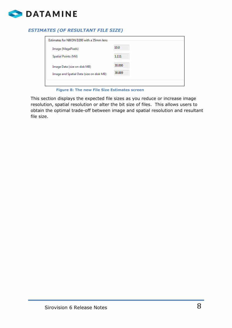
ESTIMATES (OF RESULTANT FILE SIZE)
Figure 8: The new File Size Estimates screen
This section displays the expected file sizes as you reduce or increase image
resolution, spatial resolution or alter the bit size of files. This allows users to
obtain the optimal trade-off between image and spatial resolution and resultant
file size.

Sirovision 6 Release Notes
9
Merge multiple 3D mosaics into a single composite image
Figure 9: The new ‘Tools’ drop down menu
A new function has been added to the TOOLS menu to allow the user to merge
multiple 3D mosaics in to a single composite image with options to reduce
image and spatial resolutions in order to reduce file size and memory
requirements. This single ‘super-mosaic’ can be loaded in to Sirovision without
the need for all the support files (2D images, task and matching files) used to
generate the individual 3D images in Project Explorer. This function will allow
users to analyse much larger scaled images and generate 3D models of whole
pits.
Figure 10: The new ‘Merge Files’ screen
Any 3D image or 3D mosaic can be selected from any directory and Image
Reduction Factors can be applied to each image. An Estimated Output File Size
is displayed in MB.
If any mapped objects such as structures have already been mapped on a
selected 3D image or 3D mosaics to be merged, these objects will be safely
merged in to the new composite image. If structural mapping has been

Sirovision 6 Release Notes
10
completed already, then user can afford to reduce the composite image
resolution to reduce file sizes and loading times.
SUGGESTED WORKFLOW IS TO MAP STRUCTURE ON INDIVIDUAL MOSAICS
FOR MAXIMISED ACCURACY, AND THEN MERGE MULTIPLE MOSAICS WITH
REDUCED RESOLUTION TO REDUCE FILE SIZE AND INCREASE LOAD SPEEDS
WHILST KEEPING THE ACCURACY OF THE MAPPED STRUCTURAL DATA
INTACT.
New ability to map planes across 3D mosaics
Versions of Sirovision prior to Sirovision 6 did not allow users to map a PLANE
across the boundary of an individual 3D image, even if was part of a 3D
mosaic.
Figure 11: A Plane mapped across 3 individual 3D images comprising a mosaic
Sirovision 6 enables planes to be mapped across 3D mosaics as plane data is
now more efficiently generated and managed for exportability to other software
products including Datamine Studio.

Sirovision 6 Release Notes
11
Significant expansion of the Slope Stability Analysis tool.
Please note, a separate technical manual will be distributed for the new Slope
Stability Analysis tool and internal training will be provided to each regional
office.
Figure 12: A 3D model showing an imported curved structure and automatically
detected unstable blocks.
Sirovision 6 sees the expansion of the Slope Stability Analysis tool by
introducing more sophisticated polyhedral BLOCK analysis in addition to the
existing tetrahedral analysis which detects simple WEDGES. The availability of
tetrahedral and polyhedral analysis techniques enables users to detect ALL
types of unstable blocks in their excavation.
Figure 13: Selecting Wedge Analysis or Polyhedral Analysis in the Slope Stability
Analysis tool.
Sirovision 6 Release Notes
12
Summary of new functions:
Map or import multiple domains and enable input of geotechnical
characteristics such as rock density, cohesion and critical friction values for each domain.
Import and display Pore Pressure grids. Import and display non-planar or curved complex structures. Run polyhedral analysis to automatically detect blocks and toppling
hazards in addition to tetrahedral wedge analysis. Analyse the interaction of minor and major structures.
Run analysis on ALL digitally mapped structures simultaneously, not just two orientation sets at a time.
Final analysis considers all of the above to produce a Factor of Safety, physical location, mass and volume and stability classification of all unstable features including wedges, blocks and toppling hazards
detected on the rock wall.
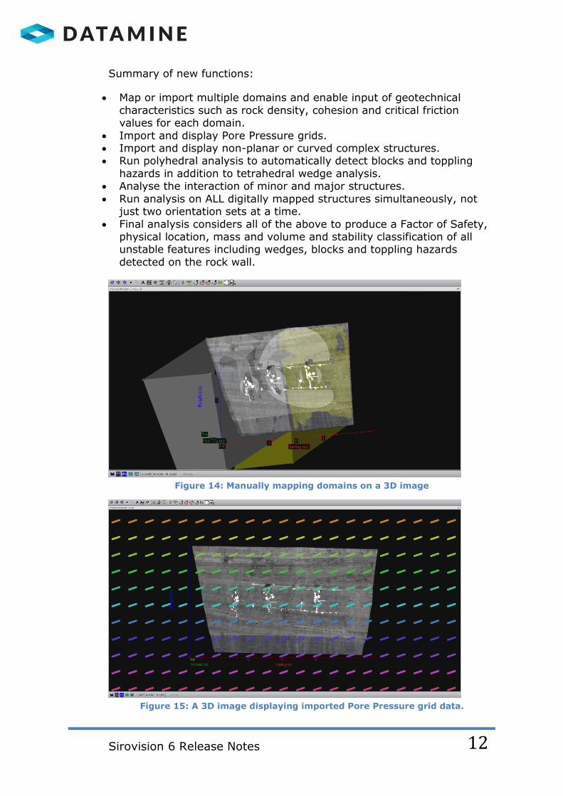
Figure 14: Manually mapping domains on a 3D image
Figure 15: A 3D image displaying imported Pore Pressure grid data.

Sirovision 6 Release Notes
13
Mineral Classification
Sirovision 6 adds a new MINERAL CLASSIFICATION function to enable the user
to select a sample area of the rock colour they wish to map, e.g. an ore body.
The software then scans the 3D model or 3D mosaic and automatically maps all
occurrences of the colours selected (ore body). As the Sirovision model is
accurately scaled, the software captures coloured bodies surface area data
which can be used to estimate ore volume.
Figure 16: A 3D model showing coal deposits automatically mapped by the Colour
Classification Tool.
Figure 17: Image Colour Classification output showing surface area data.
These Mineral Classification features can be exported via the Export Wizard as
a DXF and TEXT file.

Sirovision 6 Release Notes
14
Dip/Dip Direction Facet Shading
New DIP and DIP DIRECTION colour facet 3D view modes have been added. At
the bottom of the 3D Image View window there are two new 3D Image View
icons.
Figure 18 : A 3D Dip facet shaded image.
SHOW
DIPS
SHOW DIP
DIRECTION

Sirovision 6 Release Notes
15
TECHNICAL NOTE
Operating System
Sirovision requires a 64 bit operating system such as Windows 7, 8 or 8.1.
Graphics Cards
After installation, if the host computer has an NVidia graphics card, the first time the program
is opened, the software checks that the CUDA library is at least Version (8.17.12.6776). If it
is not, a message displays informing the user to update their graphics driver, so that the
latest CUDA library is installed. This is not an error message and does not mean your
graphics card is incompatible.

Sirovision 6 Release Notes
16
ISSUES RESOLVED IN SIROVISION V6.0
The following cases have been resolved for this version:
JIRA Card Type Description of Change
SRVS-399 New Feature A new function has been added to enable the user to manually map a plane with known centroid, dip angle, dip direction and persistence values.
SRVS-398 Feature Removal
The automated FIND PLANES function has been removed until it can be improved
SRVS-397 New Feature Added a 'Create Orientation Sets' menu option when right clicking on ORIENTATION SETS node in Object Explorer.
SRVS-394 Bug Fix Fixed bug where Export Wizard -> 3D Images -> 3DPDF export exported the same 3D image multiple times when exporting a mosaic. Image generation speed and display performance has been greatly improved.
SRVS-391 Bug Fix Fixed a bug when opening a .SJT file with an active schema displayed a message saying the schema had been modified when it had not.
SRVS-390 Bug Fix Fixed bug where the Extract Section function worked incorrectly unless the corners were defined in clockwise order.
SRVS-385 New Feature A new Mineral Classification function has been added which automatically maps all occurrences of a sample colour in a 3D image or mosaic and outputs surface area in square meters.
SRVS-384 Feature Improvement
The can edit the Survey Table Data and select Survey Point TYPE from a list of values.
SRVS-383 New Feature A new feature has been added to allow multiple 3D images and/or mosaics from different projects if required, to be merged in to a single composite 3D image with reduced resolution options but keeping all previously mapped structural data intact.
SRVS-380 Feature Improvement
Sirovision 6 installer, splash screen and Graphical User Interface rebranded to Datamine where required.
SRVS-378 Bug Fix Fixed bug where saving a 3D image using ‘File-> Save As’ caused Sirovision to crash when a duplicate file name was selected.
SRVS-371 New Feature Added new functionality to the New project Wizard – to allow the user to edit spatial and image resolution and to reduce image bit size to 8.

Sirovision 6 Release Notes
17
SRVS-368 Performance Improvement
New image and spatial resolution reduction functionality enables very fast 3D image and 3D mosaic generation speeds suitable for site demonstrations.
SRVS-358 Bug Fix Fixed bug where exporting .SJT files as a decimated 3D mesh failed. This now works where a decimated mesh is available in the data to be exported.
SRVS-353 New Feature Added ability to map Planes across a 3D mosaic.
SRVS-346 Bug Fix Fixed bug so that if ‘Reverse Mouse Zoom Control’ preference is selected, it is also applied to the georeferencing wizards.
SRVS-342 Bug Fix Fixed bug where 3D CompositeImage files could not be exported with reduced spatial resolution.
SRVS-339 Feature Improvement
Improved the performance of the ‘Remove Outliers’ function to remove spikes more effectively.
SRVS-326 Bug Fix Removed unnecessary "ID" field when generating an ‘Orientation Set Report’.
SRVS-323 Bug Fix Fixed bug where when selecting multiple 2D images and dragging them in to the Image View sometimes caused a fatal program crash.
SRVS-322 Performance Improvement
Sirovision Installer no longer produces ‘Publisher could not be verified' message during installation.
SRVS-279 Performance Improvement
The Online HELP manual SEARCH function has been improved to produce more complete search results.
SRVS-257 Bug Fix Fixed bug where changing ‘Number Bins’ in Statistics Charts did not update the chart without clicking on it to update it.
SRVS-129 New Feature Added two new 3D Dip/Dip Direction facet shading view modes to the Image View window.

.
2014 - 2015
CAE Mining Australia Pty Ltd Trading as Datamine
Level 3, 41-43 Ord Street
WEST PERTH WA 6005, AUSTRALIA
Tel: +61 8 6462 0900
www.dataminesoftware.com


