37
Installation and Technical Manual Version 0.1 DP5931v1.9 & DP5931BARv1.1
| Date post: | 09-Mar-2016 |
| Category: |
Documents |
| Upload: | sertek-servicios-tecnologicos |
| View: | 398 times |
| Download: | 33 times |

Installation and Technical Manual
Version 0.1
DP5931v1.9
&
DP5931BARv1.1

2
Safety Instructions
1. Read these instructions.
2. Keep these instructions.
3. Read all warnings.
4. Follow all instructions.
5. Do not use this apparatus near water.
6. Clean only with dry cloth.
7. Only use attachments/accessories specified by the manufacturer.
8. Unplug power during installation or servicing.
9. Refer all servicing to qualified service personnel. Servicing is required when the apparatus has been damaged in any way, such as power-supply cord or plug is damaged, liquid has been spilled or objects have fallen into the apparatus, the apparatus has been exposed to rain or moisture, does not operate normally, or has been dropped.
Legal Notice
The information contained in this document is subject to change without notice. Datapark Inc. make no warranty of any kind with regard to this material, either express or implied, except as provided herein, including without limitation thereof, warranties as to marketability, merchantability, for a particular purpose of use, or against infringement of any patent. Datapark Inc. shall not be liable for any direct, incidental, or consequential damages of any nature, or losses or expenses resulting from the use of this product and/or document.
Credits
DP is a trademark of Datapark Incorporated.
Windows is a trademark of Microsoft Corporation.
ARCNET is a trademark of Datapoint Corp.
© Copyright Datapark Inc. 1998-2006.
All Rights Reserved.
3
Typographical Conventions
This document uses the following typographical conventions:
Any example scenarios are usually given like this:
Example
This is an explanation of an example scenario.
Warning This is a warning block. It usually contains critical warnings and you should never ignore it!
Note This is a note. It usually contains some useful notes on the subject.
[Fixed Width Font Section]
This section usually contains examples of configuration
files that you’ll have to edit or examples of receipts.

4
Table of Contents
Overview.................................................................................................6
Hardware Installation ..............................................................................7
Components.....................................................................................7
Unit Location and Mounting..............................................................7
Hardware Configuration ........................................................................ 10
Setting up Jumpers and Switches .................................................. 10
Firmware updating.......................................................................... 11
Software Installation.............................................................................. 13
Installation ...................................................................................... 13
Software Updating.......................................................................... 13
System Configuration............................................................................ 14
Integrating with the System ............................................................ 14
Device Settings .............................................................................. 14
1. “Default” mode................................................................................................14
2. “Enhanced” mode ...........................................................................................15
2.1. DISCOUNT ENCODER ...........................................................................15
2.2. RATE ENCODER ....................................................................................16
2.3. PAID ENCODER .....................................................................................18
Device Functionality Check ................................................................... 20
Power Supply Check ...................................................................... 20
Communication Check ................................................................... 20
Basic Functionality Tests................................................................ 20
Troubleshooting .................................................................................... 21
Tickets (cards) not moved or positioned correctly........................... 21
Magstripe tickets (cards) not decoded or encoded correctly ........... 21
“Test mode” and “Jitter test” ........................................................... 21
1. TEST MODE ...............................................................................................22
2. JITTER TEST .............................................................................................26

5
Specifications........................................................................................28
Manual Revisions.................................................................................. 29
Appendix A – DP5931 Layout ............................................................... 30
Appendix B – DP5931SM Layout .......................................................... 32
Appendix C – Dipswitch Functionalities Table....................................... 33
Appendix D – Jitter Test Graphics......................................................... 34

6
Overview
DP5931v1.9 and DP5931BARv1.1 are the latest enhanced products of DP5930 series magnetic/bar-code readers/writers. They are fast and efficient devices for reading and encoding magnetic striped (F/2F) cards or tickets and issuing or registering bar-code cards or tickets. Their unique design affords reliable reading and encoding cards with different thickness of the magnetic record. The device allows acceptance of cards or tickets from both ends. There are two read/write heads positioned in the middle of the device. Effectively this ensures a valid reading or encoding provided that the card/ticket has been applied face up. DP5931 has the capability to configure the read head for reading up to three tracks. The device can individually read and encode up to three tracks of data. DP5931 uses a servo motor enabling bi-directional use (read in, encode out). The device uses four sensors to determine a card’s position as it moves along the track. These devices are equipped with one ArcNet serial interface and two EIA-232 serial interfaces supporting proprietary Datapark protocols.
7
Hardware Installation
Components
Both products are set of 3 PCBs: DP5931/DP5931BAR (main controller board), DP5931SM (sensor board) and DP5943M (motor board). The only difference between DP5931v1.9 and DP5931BARv1.1 is that DP5931 has connectors for two mag-stripe heads while DP5931BAR has one connector for a mag-stripe head and one connector for a laser bar-code head (Avago HBCS-1100). Further all information will be referred to DP5931 except for differences. All other components such as the wheels, bands, springs and cogs have an expected usage span to match the life of read heads.
Unit Location and Mounting
Depending on the type of product (VALIDATOR, PAY STATION, ENCODER, ENTRY or EXIT STATION), where DP5931 is mounted, it is positioned either REVERSED or NOT REVERSED).
Furthermore the presence of two heads is not always compulsory because in most of the cases DP5931 is used in combination with DP5904/2 (Print Head) which requires printing onto the ticket.
Warning DP5931v1.9 may be coupled with DP5931SMv1.5 or later versions only!
Warning Do not apply power while mounting and connecting the devices!
Warning DP5931SMv1.5 may be coupled with older versions of motor board but special care of wire connections must be taken!

8
Figure 1: Global definition for directions
The table below shows mounting schemes in different products:
VALIDATOR
DP6100
(REVERSED, HEAD 1)
PAY STATION
DP7000
(REVERSED, HEAD 1)
ENCODER
DP1350
(REVERSED, HEAD 2)
ENTRY STATION
DP5900
(NOT REVERSED, HEAD 2)
EXIT STATION
DP5800
(NOT REVERSED, HEAD 1 and 2)
Table 1: DP5931 orientation and maghead positions
HEAD2 HEAD1
HEAD1
HEAD2
SENS1 SENS2
SENS3
SENS4
STRAIGHT BACKWARD
If this side is front, DP5931 orientation is referred to as NOT
REVERSED
If this side is front, DP5931 orientation is referred to as
REVERSED

9
Appendix A provides information about the location and labeling of the connectors on
board DP5931v.9.
DP5931 is power supplied via standard 3 pin connector J9 (GND, NC, +12V). When
DP5931 is used as Magstripe Reader/Writer or Barcode Reader in VALIDATOR,
PAY STATION or ENTRY/EXIT STATION, connections for communication with Host
controller (DP6010 or DP2510) and periphery device (DP5904/DP5902) have to be
established. All Datapark cables are labeled and using standardized connectors in
order to avoid incorrect couplings.
The table below provides information about the interface compatibility with other Datapark devices, depending on the type of product, which DP5931 is mounted in:
VALIDATOR
DP6100
Host controller (DP6010) with ArcNet interface connected to J8 (ARCNET)
DP5902/4 with RS232 interface connected to J6 (RS232-0)
PAY STATION
DP7000
Host controller (DP6010) with ArcNet interface connected to J8 (ARCNET)
DP5902/4 with RS232 interface connected to J6 (RS232-0)
ENCODER
DP1350
LED with serial resistor connected to
J3 at DP5931SM (see Appendix B)
ENTRY STATION
DP5900
Host controller (DP2510) with ArcNet interface connected to J8 (ARCNET)
DP5902/4 with RS232 interface connected to J6 (RS232-0)
EXIT STATION
DP5800
Host controller (DP2510) with ArcNet interface connected to J8 (ARCNET)
DP5902/4 with RS232 interface connected to J6 (RS232-0)
Table 2: Interface connections in different products

10
Hardware Configuration
Setting up Jumpers and Switches
J5 on board DP5931SM (Appendix B) is used to select “default” or “enhanced” mode. The pulse frequency of the CPU LED - D1 on board DP5931 (Appendix A) - indicates the current work mode (“default mode” - 2.5Hz, “enhanced mode” - 0.8Hz).
SW1 on board DP5931 (Appendix A) is used for configuring different functionalities. The two tables below show different configuration settings depending on the work mode and the required functionalities (white blocks indicate the positions of dip-switches):
DP5931 Default mode JP5 at DP5931SM must be in position 3-4
Not reversed
Discounts disabled
_
Reversed
Discounts disabled
_
Not reversed
Discounts enabled
at beginning
Reversed
Discounts enabled
at beginning
Not reversed
Discounts enabled
at ending
Magstripe Reader
Barcode Reader
Magstripe Writer
Reversed
Discounts enabled
at ending
Table 3: Dipswitches positions in “Default” mode
1 8
ON
1 8
ON
1 8
ON
1 8
ON
1 8
ON
1 8
ON

11
DP5931 Enhanced mode JP5 at DP5931SM must be in position 2-3
Discount Encoder – 10 bits Shaded switches assign
discount number 0÷127
in binary format
Discount Encoder – 8 bits Shaded switches assign
discount number 0÷31
in binary format
Rate Encoder Shaded switches assign
rate number 0÷15
in binary format
Paid Encoder Functionality used to encode inserted tickets as paid
Tests using PC application
specific software
_
Test & Service mode
Tests using general PC
terminal software
_
Table 4: Dipswitches positions in “Enhanced” mode
Firmware updating
J1 (Appendix A) is the JTAG header connector used for programming. In order to reprogram the firmware you need:
• USB debug adapter product of Silicon Laboratories: http://www.silabs.com/tgwWebApp/public/web_content/products/Microcontrollers/en/USBDebug.htm
• A programming HEX file (e. g. DP5931vXX.hex) supplied by Datapark Inc.
• Programming PC application software. Download and install Flash programming utilities from:
1 8
ON
1 8
ON
1 8
ON
1 8
ON
1 8
ON
1 8
ON

12
http://www.silabs.com/public/documents/software_doc/othersoftware/Microcontrollers/en/UtilDLL.exe and carefully read the User's guide: http://www.silabs.com/public/documents/tpub_doc/uguide/Microcontrollers/en/USB_Debug_Adapter_UG.pdf
Check http://support.dataparkinc.com WEB site for the latest updates.

13
Software Installation
Installation
There are different applications (Set25.exe, ConfigINI.exe…) for configuring and monitoring the functionalities depending on the product which DP5931 is mounted in. All software modules are included in Datapark Installation Package. Refer to the corresponding software or product manual for more information.
When used as RATE ENCODER, DISCOUNT ENCODER or PAID ENCODER, DP5931 works as an independent off-line device and does not support ArcNet or RS232 communication with Host Controllers or PC.
Specific Software is used for Firmware Updating.
DockLight.exe or Rcv.exe is used for different tests.
Software Updating
Replace the existing application (located in C:\Datapark) with the latest version, provided by Datapark Inc.
Check http://support.dataparkinc.com WEB site for the latest updates.
14
System Configuration
Integrating with the System
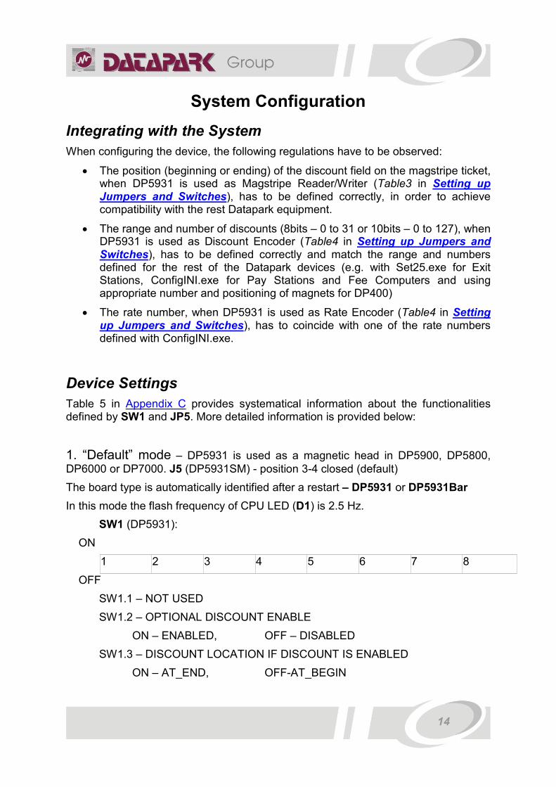
When configuring the device, the following regulations have to be observed:
• The position (beginning or ending) of the discount field on the magstripe ticket, when DP5931 is used as Magstripe Reader/Writer (Table3 in Setting up Jumpers and Switches), has to be defined correctly, in order to achieve compatibility with the rest Datapark equipment.
• The range and number of discounts (8bits – 0 to 31 or 10bits – 0 to 127), when DP5931 is used as Discount Encoder (Table4 in Setting up Jumpers and Switches), has to be defined correctly and match the range and numbers defined for the rest of the Datapark devices (e.g. with Set25.exe for Exit Stations, ConfigINI.exe for Pay Stations and Fee Computers and using appropriate number and positioning of magnets for DP400)
• The rate number, when DP5931 is used as Rate Encoder (Table4 in Setting up Jumpers and Switches), has to coincide with one of the rate numbers defined with ConfigINI.exe.
Device Settings
Table 5 in Appendix C provides systematical information about the functionalities defined by SW1 and JP5. More detailed information is provided below:
1. “Default” mode – DP5931 is used as a magnetic head in DP5900, DP5800, DP6000 or DP7000. J5 (DP5931SM) - position 3-4 closed (default)
The board type is automatically identified after a restart – DP5931 or DP5931Bar
In this mode the flash frequency of CPU LED (D1) is 2.5 Hz.
SW1 (DP5931):
ON
1 2 3 4 5 6 7 8
OFF
SW1.1 – NOT USED
SW1.2 – OPTIONAL DISCOUNT ENABLE
ON – ENABLED, OFF – DISABLED
SW1.3 – DISCOUNT LOCATION IF DISCOUNT IS ENABLED
ON – AT_END, OFF-AT_BEGIN

15
SW1.4 – DIRECTIONAL SWITCH
ON – NOT_REVERSED, OFF - REVERSED
SW1.5 – NOT USED
SW1.6 – NOT USED
SW1.7 – NOT USED
SW1.8 – NOT USED
2. “Enhanced” mode - DP5931 is used as a discount encoder (8 or 10 bits), rate encoder, paid encoder and test mode. J5 (DP5931SM) – position 2-3 closed
SWITCHING THE WORK MODE WHILE IN „ENHANCED MODE“ CAN BE CARRIED OUT ONLY AFTER SELECTING THE CORRESPONDING MODE USING SW8, SW7, SW6 AND RESETTING DP5931 !!!
In this mode the flash frequency of CPU LED (D1) is 0.8 Hz. External LED with resistor is connected to J2, J3 (open drain) of the DP5931SM board for indication to the user (USER_LED). The flash frequency of the external led is – 2.5Hz.
SW1 (DP5931):
ON
1 2 3 4 5 6 7 8
OFF
2.1. DISCOUNT ENCODER
SW1.8 – DISCOUNT ENCODER MODE SELECT
ON – 10 bits discount mode, OFF – 8 bits discount mode
IF SW1.8 = ON (10 bits discount mode)
SW1.7, SW1.6, SW1.5, SW1.4, SW1.3, SW1.2, SW1.1 - discount number from 0 to 127
IF SW1.8 = OFF, SW1.7 = OFF, SW1.6 = OFF (8 bits discount mode)
SW1.5, SW1.4, SW1.3, SW1.2, SW1.1 - discount number from 0 to 31
Function
To encode 8 or 10 bits discount onto DATAPARK ticket or AMANO ticket after converting it to a DATAPARK ticket.
Functionality
In this mode DP5931 works as an independent off-line device and does not support ArcNet (J8) or RS232 communication through J6 and J7.

16
Only when decoding DATAPARK ticket or AMANO ticket, regardless of whether or not there is a discount field, the ticket records as a DATAPARK ticket with discount field, after which encodes the assigned from the switches discount number (8 or 10 bits). After checking the new record the result is displayed onto the USER_LED.
When the discount record and encoding is successful – USER_LED keeps flashing until the ticket is pulled away.
If the decoding is unsuccessful, decodes different type (card or other) - USER_LED is switched off until the card is pulled away.
Working cycle when the encoding is successful:
− read stripe and decode ticket <--------------- − compose ticket and write data ---------------> − write discount <--------------- − read stripe and verify data and discount # ---------------> OK - USER_LED = ON Working cycle for the first unsuccessful decoding:
− read stripe and decode ticket <--------------- − move stripe ---------------> − read stripe and decode ticket <--------------- − compose ticket and write data ---------------> − write discount <--------------- − read stripe and verify data and discount # ---------------> OK - USER_LED = ON Working cycle for the first and second unsuccessful decoding:
− read stripe and decode ticket <--------------- − move stripe ---------------> − read stripe and decode ticket <--------------- − move stripe ---------------> BAD–USER_LED = OFF Working cycle when failing to verify and repeated record with successful result:
− read stripe and decode ticket <--------------- − compose ticket and write data ---------------> − write discount <--------------- − read stripe and verify data and discount # ---------------> BAD − move stripe <-------------- − compose ticket and write data ---------------> − write discount <--------------- − read stripe and verify data and discount # ---------------> OK – USER_LED = ON
2.2. RATE ENCODER
SW1.8, SW1.7, SW1.6 - Rate encoder select
IF SW1.8 = OFF, SW1.7 = ON, SW1.6 = OFF
SW1.4, SW1.3, SW1.2, SW1.1 - rate number
SW1.5 - NOT USED

17
Function
To re-encode DATAPARK tickets with rate, set from SW1.4, SW1.3, SW1.2 and SW1.1 (0...15 max)
Functionality
In this mode DP5931 works as an independent off-line device and does not support ArcNet (J8) or RS232 communication through J6 and J7.
Only when decoding a DATAPARK ticket, the last one records as a DATAPARK ticket with rate, assigned from SW1.4, SW1.3, SW1.2, SW1.1. After the new record is checked, the result is indicated onto the USER_LED.
When the record of the new rate is successful – USER_LED keeps flashing until the ticket is pulled away.
When decoding a ticket with rate, corresponding to the assigned (When decoding ticket with rate corresponding to the one assigned from the switches) the ticket does not re-encode, only indicates the successful encoding - USER_LED keeps flashing until the ticket is pulled away.
If the decoding is unsuccessful, decodes a different type (card or other) - USER_LED is switched off until the card is pulled away.
When decoding a DATAPARK ticket and finding a discount field, while re-encoding, the discount field is kept so as to be possible to apply the discount with the DP400 device.
Working cycle when there is a successful encoding with a change of rate:
− read stripe and decode ticket <--------------- − compose ticket and write data ---------------> − read stripe and verify data and rate # <--------------- − move stripe ---------------> OK - USER_LED = ON Working cycle when decoding a ticket with rate even to the assigned:
− read stripe and decode ticket <--------------- − move stripe ---------------> OK - USER_LED = ON Working cycle when there are two unsuccessful attempts for ticket decoding:
− read stripe and decode ticket <--------------- − move stripe ---------------> − read stripe and decode ticket <--------------- − move stripe ---------------> BAD–USER_LED = OFF Working cycle when there is one unsuccessful ticket decoding and a consecutive successful decoding and recording:
− read stripe and decode ticket <--------------- − move stripe ---------------> − read stripe and decode ticket <--------------- − compose ticket and write data ---------------> − read stripe and verify data and rate # <--------------- − move stripe ---------------> OK - USER_LED = ON
18
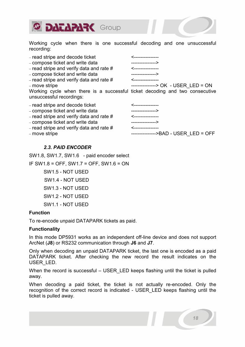
Working cycle when there is one successful decoding and one unsuccessful recording:
− read stripe and decode ticket <--------------- − compose ticket and write data ---------------> − read stripe and verify data and rate # <--------------- − compose ticket and write data ---------------> − read stripe and verify data and rate # <--------------- − move stripe ---------------> OK - USER_LED = ON Working cycle when there is a successful ticket decoding and two consecutive unsuccessful recordings:
− read stripe and decode ticket <--------------- − compose ticket and write data ---------------> − read stripe and verify data and rate # <--------------- − compose ticket and write data ---------------> − read stripe and verify data and rate # <--------------- − move stripe --------------->BAD - USER_LED = OFF
2.3. PAID ENCODER
SW1.8, SW1.7, SW1.6 - paid encoder select
IF SW1.8 = OFF, SW1.7 = OFF, SW1.6 = ON
SW1.5 - NOT USED
SW1.4 - NOT USED
SW1.3 - NOT USED
SW1.2 - NOT USED
SW1.1 - NOT USED
Function
To re-encode unpaid DATAPARK tickets as paid.
Functionality
In this mode DP5931 works as an independent off-line device and does not support ArcNet (J8) or RS232 communication through J6 and J7.
Only when decoding an unpaid DATAPARK ticket, the last one is encoded as a paid DATAPARK ticket. After checking the new record the result indicates on the USER_LED.
When the record is successful – USER_LED keeps flashing until the ticket is pulled away.
When decoding a paid ticket, the ticket is not actually re-encoded. Only the recognition of the correct record is indicated - USER_LED keeps flashing until the ticket is pulled away.

19
If the decoding is unsuccessful, decodes a different type (card or ticket) - USER_LED is switched off until the card is pulled away.
When decoding a DATAPARK ticket and finding a discount field, while re-encoding, the discount field is preserved so as to be possible to apply the discount with the DP400 device.
Working cycle when the encoding is successful:
− read stripe and decode ticket <--------------- − compose ticket and write data ---------------> − read stripe and verify data <--------------- − move stripe ---------------> OK - USER_LED = ON Working cycle when decoding a paid ticket:
− read stripe and decode ticket <--------------- − move stripe ---------------> OK - USER_LED = ON Working cycle when there are two unsuccessful attempts for ticket decoding:
− read stripe and decode ticket <--------------- − move stripe ---------------> − read stripe and decode ticket <--------------- − move stripe ---------------> BAD–USER_LED = OFF Working cycle when there is one unsuccessful ticket decoding and consecutive successful decoding and recording:
− read stripe and decode ticket <--------------- − move stripe ---------------> − read stripe and decode ticket <--------------- − compose ticket and write data ---------------> − read stripe and verify data <--------------- − move stripe ---------------> OK - USER_LED = ON Working cycle when there is a successful ticket decoding and two consecutive unsuccessful recordings:
− read stripe and decode ticket <--------------- − compose ticket and write data ---------------> − read stripe and verify data <--------------- − compose ticket and write data ---------------> − read stripe and verify data <--------------- − move stripe --------------->BAD - USER_LED = OFF

20
Device Functionality Check
Power Supply Check
After supplying power LEDs D4 (Green), D17 (Yellow), D11 (Red) should be constantly lit, indicating that the corresponding electronic circuits (+3,3V, +5V, +12V) have been established properly.
Communication Check
After initialization of the connection with the Host Controller (DP2510 if mounted in Entry or Exit Station, and DP6010 if mounted in Validator or Pay Station) the interface group control LEDs for ARCNET communication D13 - TX (Red), D12 - RX (Red) should be lit with steady and dim light.
After initialization of the connection with the periphery device (e.g. DP5904/DP5902 if mounted in Entry or Exit Station, Validator or Pay Station) the interface group control LEDs for RS232-0 communication D2 – TX (Green), D9 - RX (Red) should start blinking each time when DP5931 communicates with the periphery device (e.g. when a ticket is being issued or moving between the two devices).
Basic Functionality Tests
After restart DP5931 automatically performs check-up of the functioning of RAM, Hall sensor, ARCNET chip and connections.
The work of DP5931 is possible only after a successful test.
If the test is unsuccessful:
RAM – the following LEDs flash: CPU (D1), SENS1, SENS2, SENS3, SENS4 and USER_LED (connected to J2 on board 5931SM). An error code is send through COM0 and COM1 - 100. In the presence of this error the RAM chip should be carefully examined, a check for short circuit or suspension of the switches to and from the RAM chip should be done.
Hall sensor – the following LEDs flash: CPU, SENS1, SENS2, SENS3, SENS4 and USER_LED. An error code is send through COM0 and COM1 – 101. In the presence of this error the Hall sensor should be carefully examined, check also for the wholeness and the correctness of the cable between the motor board and the sensor board.
ArcNet – the following LEDs flash: CPU, SENS1, SENS2, SENS3, SENS4 and USER_LED. An error code is send through COM0 and COM1 – 102. In the presence of this error the ArcNet chip should be carefully examined, also the chip performing the decoding, check for short circuit or broken path, etc.

21
Troubleshooting
Tickets (cards) not moved or positioned correctly
Check the condition and clean if necessary the tracking sensors Sens1, Sens2, Sens3 and Sens4.
Ensure the Hall sensor LED (D16) is indicating correctly the motor rotating steps – it has to flash four times per revolution. If the sensor is not checking correctly the motor speed, gently move the sensor to within 0.08” or 2 mm of the magnetic wheel attached to the motor’s drive shaft.
Magstripe tickets (cards) not decoded or encoded correctly
In most of the cases the reason for this is that the magnetic heads have become dirty. Cleaning of the magnetic heads is the most frequent maintenence requirement. In order to avoid this clean the magnetic heads at least once every 60 days. We recommended using and supply upon request Clean Team head cleaning cards. Run the cleaning card through the device five to six times as per the packet directions. When extremely dirty remove and clean the heads with a cloth.
“Test mode” and “Jitter test”
If the operations described above cannot approve the operation or any not physically observable problems occur, DP5931 is connected to a PC in order to be tested for incorrect functioning and/or accepting different parameters.
“Enhanced mode” has to be selected by closing J5 (DP5931SM) into position 3-4.
SW1.8, SW1.7, SW1.6 - paid encoder select
IF SW1.8 = OFF, SW1.7 = ON, SW1.6 = ON
SW1.5 - NOT USED
SW1.4 - NOT USED
SW1.3 - NOT USED
SW1.2 - NOT USED
SW1.1 = ON - DP5931 diagnostic, parameters change, functionality test with data to the PC
SW1.1 = OFF - jitter test
WHEN SWITCHING BETWEEN “TEST MODE” AND “JITTER TEST”, DP5931 RESETTING IS NOT REQUIRED!

22
1. TEST MODE
SW1.1 = ON - test
Function
− To be used in the manufacturing for testing the functionality of DP5931, for evaluation of the quality and the work process.
− To set the functional parameters in exploitation conditions. − Evaluating the work quality of DP5931. Program requirements: DockLight.exe or Rcv.exe should be used.
Hardware requirements: To work in this mode a RS232 cable is required, which should be connected between the PC and RS232-0 (J6) or RS232-1 (J7) of DP5931.
Functionality
After restart (or switching SW1.1 from OFF to ON) the PC screen will display:
1. ReadStripe 2. WriteTest 3. ReadDiscount 4. MotorTest 5. GetInfo 6. Options
Using the keyboard buttons – 1 to 6, select the corresponding functionality.
“1. ReadStripe “
Used for reading and decoding magnetic striped DATAPARK ticket, DATAPARK card, AMANO ticket.
After selecting ReadStripe on the display will appear - “Insert a stripe...” and a card should be inserted.
The card can be inserted from either side of the DP5931.
After reading the card the display will show - “F2F [F] or Strobe/Data [S]?”
If 'S' is selected – the card will be decoded basing on the data, received from the hardware FM decoding of the MagTek chip.
If 'F' is selected – the decoding will be processed basing on the F2F signal and the times measured.
Depending on the options chosen from ‘6’ – “Options” menu, additional information about the decoding process is visualized.
“2. WriteTest”
A record on the magnetic card with density of around 100 bits/inch is used. This test should be used for evaluating the record quality and the jitter.

23
After selecting WriteTest, option for selecting 4 different types of test records is provided on the display - “[0]'0', [1] '1', [2] '0-1' or [3] '0-1-01-0 select?”
[0] – 350 zero bits are recorded onto the magnetic stripe
[1] – 60 leading zero bits, followed by 240 trailing one (1) bits and 50 zero bits are recorded onto the magnetic stripe
[2] – 60 leading zero bits, followed by 240 alternating '1-0' bits and 50 zero bits are recorded onto the magnetic stripe
[3] – 50 leading zero bits, followed by 150 trailing one(1) bits, 100 alternating '1-0' and 50 zero bits are recorded onto the magnetic stripe
After that “Insert a stripe...” is displayed.
After recording the data, information about the record parameters is displayed:
Calibr. Time: [0x0000E0E1] - the measured time for a certain pulse number from the HALL sensor
Wide pulse: [943] - wide pulse duration ('0') when recording
Short pulse: [468] - short pulse duration ('1') when recording
Hall pulses: 52 - Hall sensor's number of steps for positioning the card, to be pulled
“3. ReadDiscount”
Decoding a discount encoded with DP400 onto DATAPARK ticket.
If the decoding is successful the discount number will be displayed.
If the decoding is unsuccessful or the discount number is missing - “Disc. Error” will be displayed.
Depending on the options chosen from ‘6’ – “Options” menu, additional information about the discount decoding process is visualized. For decoding of “8” or “10” bits discounts it is essential that the corresponding discount type is chosen from the “6.Options” menu. Decoding of discounts encoded onto AMANO tickets can not be done. If there is a discount encoded on AMANO ticket, “1. ReadStripe” - [F] should be used for decoding of AMANO ticket and the corresponding discount.
“4. MotorTest”
This test is used for evaluation of the motor work capacity and the control elements.
After selecting '4' on the display will appear - “[F]orward, [B]ackward or [S]top?”
When choosing [F] or [B] the motor will start spinning in the corresponding direction and the same sign will appear on the display. The motor spin direction can be reversed repeatedly. After the test has accomplished, select [S] to exit.

24
The motor spin direction does not depend on SW1.4
[F]orward is the default direction and the motor should spin in such a way, so that when inserting a card, the last one should have a left motion direction, when facing DP5931 from the board side.
[B]ackward is the default direction and the motor should spin in such a way, so that when inserting a card, the last one should have a right motion direction when facing DP5931 from the board side.
If the motor spin direction is different than the one described above, the defect should be corrected.
“5. GetInfo”
This option provides information about the DP5931 work parameters.
After choosing “5.GetIInfo” the display will show:
DP5931BAR Board - firmware ver.15.0 – Sep. 8 2006 09:00:04
SN: 0060801B
Life Time : 1234 [h]
Temperature : 24.18 [deg C]
DIP_SWITCH : 0xE9
FRONT_SENS : OFF – 0.2 [V]
FRONT_HEAD_SENS : OFF – 0.2 [V]
BACK_HEAD_SENS : OFF – 0.2 [V]
BACK_SENS : ON – 2.4 [V]
Discount format : 8 bits
OEM Tickets : accepted
ArcNet ID 0xE0 : 1st
EventMode : Enabled
Description of the information:
DP5931BAR Board - firmware ver.15.0 – Sep. 8 2006 09:00:04
------------------------ -------------------- --------------------------
| | |
| | |---------- MM-DD-YY hh:mm:ss
| | version build
| |----------- firmware version
|---------------- board type – DP5931 or DP5931BAR
25
SN: 0060801B - serial number - max. 8 numbered letters. Factory defined.
Life Time : 1234 [h] – non resetable – the time in hours, when the DP5931 has been powered.
Temperature : 24.18 [deg C] - the temperature at the moment
DIP_SWITCH: 0xE9 - state of the DIP switch (SW1 – Appendix A) switches (0 – ON, 1 – OFF). Positions of SW1.2 to SW1.8 can be changed and GetInfo reselected in order to monitor the condition of SW1. Changing the position of SW1.1 from ON to OFF leads to entering “jitter and subjitter” test mode.
FRONT_SENS : OFF – 0.2 [V] - state of the FRONT sensor – the most left one faces the board.
FRONT_HEAD_SENS : OFF – 0.2 [V] - state of the FRONT_HEAD sensor – the middle left sensor faces the board. OFF – means not in operation (no stripe) and the measured voltage level.
BACK_HEAD_SENS : ON – 2.3 [V] - state of the BACK_HEAD sensor – the middle right sensor faces the board. ON – means in operation (stripe) and the measured voltage level.
BACK_SENS : ON – 2.4 [V] - state of the BACK sensor – the most right sensor faces the board. ON – means in operation (stripe) and the measured voltage level.
Discount format : 8 bits - 8 or 10 bits. Depending on the assigned format, when reading a ticket with a discount, the discounts are identified with numbers from 0...31 or 0…127
OEM Tickets : accepted - accepted or refused. Permits or prohibits the decoding of tickets with OEM format.
ArcNet ID 0xE0 : 1st - 1st or 2nd. Depending on the way it is used, assign an ID in the ArcNet network. It is essential to select 2nd only if DP5931 is used in “4 way reading” and DP5931 is used as a second head. In all other cases should be used as 1st. By default it is set to work as 1st.
EventMode : Enabled - Enabled or Disabled. If event mode enabled – when changing the state on any of the sensors, an event 0x80 is generated to the host device. If event mode disabled – DP5931 is slave device and information about any change of the sensors state is given only after making a request from the host device.
If changing a sensor state and selecting GetInfo, the new state is visualized. For sensors not set in operation, a valuation of the contamination of the sensors is based on the measured voltage levels.
“6. Options”
Using this menu some of the DP5931 parameters can be changed. These parameters are kept in NVRAM.

26
After selecting “Options” the following menu appears on the display:
Dump [R]awData - disabled
Dump [F]MDecode - disabled
[D]iscount format - 8 bits
[O]EM Tickets - refused
[A]rcNet ID - 1st
[E]xit
It provides information about the current parameters state. Each of the parameters has two possible states.
Choosing:
[R] – switches between enable/disable. By default is “disable”. Allowing of this parameter leads to visualization of the buffers with data (the measured times when reading, decoded bit buffers) in this test mode and the use of “ReadStripe” and “ReadDiscount”. This parameter is not kept in NVRAM.
[F] – switches between enable/disable. By default is “disable”. Allowing of this parameter leads to visualization of an additional information when decoding F2F in test mode and the use of “ReadStripe” and “ReadDiscount”. This parameter is not used in NVRAM.
[D] – switches between '8' or '10' bits. '8' bits by default. Depending on the selected format, decodes discounts with numbers from 0..31 or 0..127. This parameter is kept in NVRAM. NOTE: FOR THE CORRECT DECODING OF THE DISCOUNT NUMBERS IT IS ESSENTIAL THAT THE PARAMETER IS CORRECTLY SET.
[O] – switches between accepted or refused. By default is 'refused'. If the 'refused' mode is chosen only DATAPARK cards, tickets and ABA cards are decoded. This parameter is saved in NVRAM.
To decode OEM tickets (AMANO) it is compulsory this parameter to be 'accepted'
[A] – switches between '1st' or '2nd'. By default is '1st'. It should be set '2nd' only when using DP5931 as a second head for '4 way reading “. This parameter is kept in NVRAM.
For the correct work of DP5931 it is essential that this parameter is correctly set.
[E] – exit the options menu. A record in NVRAM is made on exit only if there is a change of some of the [D], [O], [A] parameters.
2. JITTER TEST
SW1.1 = OFF - jitter test
When SW1 = OFF position, using MagHeadTest.exe a valuation of the reading and recording quality of DP5931 can be done.

27
This work mode is used for testing DP5931 in the manufacturing and also for periodical valuation of the exploitation process.
Program requirement: MagHeadTest.exe
Hardware requirements: To work in this mode a RS232 cable is essential which is connected between the PC and COM0 or COM1 of DP5931.
DP5931 is in stand by mode waiting for commands from the MagHeadTest program. After reading the magnetic stripe card, the data is send to the MagHeadTest application, where the record quality is graphically displayed and a valuation of the jitter, subjitter and Dispersion parameters is given.
Valuation of the DP5931 work quality (board + mechanics)
I. Valuation with a standard card (jitter max = 1%, subjitter max = 1%)
1. For DP5931 work mode select “jitter” test 2. Using MagHeadTest the standard card is four-way read.
The received graphics and results for the jitter and subjitter should not be more than 10%. If there are values more than that, the board and the mechanics should be re-examined in order to find the reasons. Products with higher jitter and subjitter should not be allowed!
II. Valuation of the recording and reading of DP5931 (board + mechanics)
1. While in test mode select “WriteTest” 2. Four types of cards are recorded with “0', '1', '2', '3' 3. DP5931 work mode switches to “jitter” test 4. Using MagHeadTest.exe each card is four-way read for valuating the jitter and subjitter.
The received graphics and results for the jitter and subjitter should not be more than 20%. If there are values more than that, the board and the mechanics should be re-examined in order to find the reasons. Products with higher jitter and subjitter should not be allowed!
Some exemplary jitter test graphics are provided in Appendix D.

28
Specifications
Power supply: 12V +20% / - 5%
Power consumption: 0.5A nom. / 2.5A max.
Ambient temperature: -10 to +50 0C / +14 to +120 0F
Relative humidity: 10% to 90% non condensing
Dimensions (W x H x L): 130x100x195 mm / 5.1x3.9x7.7 in
Usable media coercivity 250 to 1000 Oe
MTBF > 1000 read/write cycles

29
Manual Revisions
Version 0.1
[10/13/2006]
This is the first version of the document.

30
Appendix A – DP5931 Layout
Figure 2: DP5931 connectors, switches and LEDs
1 – J8 - ARCNET connector (RG11 - 4 pin)
2 – J7 - RS232-1 connector (RG11 - 4 pin)
3 – J6 - RS232-0 connector (RG11 - 4 pin)
4 – J9 - Power supply (pin1: GND, pin2: NC, pin3: +12V)
5 – D4 (yellow), D17 (green), D11 (red) - Power supplying group control LEDs for +3,3V, +5V, +12V
6 – D16 (yellow), D8 (red), D7 (red), D6 (red), D5 (red) - Sensors group control LEDs for Hall, Sens1, Sens2, Sens3 and Sens4 correspondingly. Hall indicates whether the magnetic sensor is successfully checking the speed of the motor. Sens1, Sens2, Sens3 and Sens4 indicate the position of the card/ticket while moving along the track
7 – D13 (red), D12 (red) - (TX, RX) - Interface group control LEDs for ARCNET
8 – D3 (green), D10 (red) - (TX, RX) - Interface group control LEDs for RS232-1
9 – D2 (green), D9 (red) - (TX, RX) - Interface group control LEDs for RS232-0
10 – J4 - Connector for MAGHEAD1 (6 pin)
11 – J5 - Connector for MAGHEAD2 (6 pin)
12 – J2 - Test points for measuring the levels from the optical sensors
13 – J1 - JTAG interface for micro-controller programming (10 pin)
4 5 6 7 8 9
1 2 3
10 12 11 13 17 14 15 16

31
14 – S1 - RESET button
15 – D1 (green) - CPU LED - Status indicator for the current work mode
16 – SW1 - 8 position DIPswitch for configuration
17 – JP3, JP1, JP2 - (BIAS-, TERM, BIAS+) - Set of jumpers for configuring the ARCNET line

32
Appendix B – DP5931SM Layout
Figure 3: DP5931SM connectors and jumpers
1 – J1 - Connector for DP5931 board
2 – J2 - Reserved for future use
3 – J3 - User LED header (in ENCODER mode)
4 – J4 - Connector for DP5943M board
5 – J5 - Jumper defining “default” (position 3-4) or “enhanced” (position 2-3) work mode (pin 4 is most left as shown on Figure3; pin 1 is factory removed)
6 – J6 - Connector for DP5931 board
1
2 3 5 4
6

33
Appendix C – Dipswitch Functionalities Table
MagHead- DP5931
DP5931SM board
DP5931 board
“Default” mode
JP5 – 3-4 ON
SW1.8 SW1.7 SW1.6 SW1.5 SW1.4 SW1.3 SW1.2 SW1.1
Magstripe reader/writer
Barcode reader
NotUsed NotUsed NotUsed NotUsed Directional switch
ON – not reversed
OFF - reversed
Discount Location
ON- at end
OFF – at beginning
Discount enable
ON – enabled
OFF - disabled
NotUsed
“Enhanced” mode
JP5 – 2-3 ON
SW1.8 SW1.7 SW1.6 SW1.5 SW1.4 SW1.3 SW1.2 SW1.1
Discount encoder –10 bits
ON SW1.7 ... SW1.1 select discount number from 0 to 127
Discount encoder – 8 bits
OFF OFF OFF SW1.5...SW1.1 select discount number from 0 to 31
Rate encoder OFF ON OFF NotUsed SW1.4...SW1.1 select rate number from 0 to15
Paid encoder OFF OFF ON NotUsed NotUsed NotUsed NotUsed NotUsed
Test mode OFF ON ON NotUsed NotUsed NotUsed NotUsed ON – test
OFF-jitter test
Table 5: Dipswitch functionalities

34
Appendix D – Jitter Test Graphics

35

36

37


